EP4339991A1 - Fuse-switch-disconnector assembly - Google Patents
Fuse-switch-disconnector assembly Download PDFInfo
- Publication number
- EP4339991A1 EP4339991A1 EP22862756.8A EP22862756A EP4339991A1 EP 4339991 A1 EP4339991 A1 EP 4339991A1 EP 22862756 A EP22862756 A EP 22862756A EP 4339991 A1 EP4339991 A1 EP 4339991A1
- Authority
- EP
- European Patent Office
- Prior art keywords
- fuse
- switch
- disconnector
- assembly
- cover body
- Prior art date
- Legal status (The legal status is an assumption and is not a legal conclusion. Google has not performed a legal analysis and makes no representation as to the accuracy of the status listed.)
- Pending
Links
Images




Classifications
-
- H—ELECTRICITY
- H01—ELECTRIC ELEMENTS
- H01H—ELECTRIC SWITCHES; RELAYS; SELECTORS; EMERGENCY PROTECTIVE DEVICES
- H01H85/00—Protective devices in which the current flows through a part of fusible material and this current is interrupted by displacement of the fusible material when this current becomes excessive
- H01H85/02—Details
- H01H85/47—Means for cooling
-
- H—ELECTRICITY
- H01—ELECTRIC ELEMENTS
- H01H—ELECTRIC SWITCHES; RELAYS; SELECTORS; EMERGENCY PROTECTIVE DEVICES
- H01H19/00—Switches operated by an operating part which is rotatable about a longitudinal axis thereof and which is acted upon directly by a solid body external to the switch, e.g. by a hand
- H01H19/64—Encased switches adapted for ganged operation when assembled in a line with identical switches, e.g. stacked switches
-
- H—ELECTRICITY
- H01—ELECTRIC ELEMENTS
- H01H—ELECTRIC SWITCHES; RELAYS; SELECTORS; EMERGENCY PROTECTIVE DEVICES
- H01H85/00—Protective devices in which the current flows through a part of fusible material and this current is interrupted by displacement of the fusible material when this current becomes excessive
- H01H85/02—Details
- H01H85/25—Safety arrangements preventing or inhibiting contact with live parts, including operation of isolation on removal of cover
-
- H—ELECTRICITY
- H01—ELECTRIC ELEMENTS
- H01H—ELECTRIC SWITCHES; RELAYS; SELECTORS; EMERGENCY PROTECTIVE DEVICES
- H01H85/00—Protective devices in which the current flows through a part of fusible material and this current is interrupted by displacement of the fusible material when this current becomes excessive
- H01H85/02—Details
- H01H85/30—Means for indicating condition of fuse structurally associated with the fuse
- H01H85/303—Movable indicating elements
-
- H—ELECTRICITY
- H01—ELECTRIC ELEMENTS
- H01H—ELECTRIC SWITCHES; RELAYS; SELECTORS; EMERGENCY PROTECTIVE DEVICES
- H01H89/00—Combinations of two or more different basic types of electric switches, relays, selectors and emergency protective devices, not covered by any single one of the other main groups of this subclass
-
- H—ELECTRICITY
- H01—ELECTRIC ELEMENTS
- H01H—ELECTRIC SWITCHES; RELAYS; SELECTORS; EMERGENCY PROTECTIVE DEVICES
- H01H9/00—Details of switching devices, not covered by groups H01H1/00 - H01H7/00
- H01H9/02—Bases, casings, or covers
- H01H9/0264—Protective covers for terminals
-
- H—ELECTRICITY
- H01—ELECTRIC ELEMENTS
- H01H—ELECTRIC SWITCHES; RELAYS; SELECTORS; EMERGENCY PROTECTIVE DEVICES
- H01H9/00—Details of switching devices, not covered by groups H01H1/00 - H01H7/00
- H01H9/10—Adaptation for built-in fuses
-
- H—ELECTRICITY
- H01—ELECTRIC ELEMENTS
- H01H—ELECTRIC SWITCHES; RELAYS; SELECTORS; EMERGENCY PROTECTIVE DEVICES
- H01H9/00—Details of switching devices, not covered by groups H01H1/00 - H01H7/00
- H01H9/02—Bases, casings, or covers
- H01H2009/0292—Transparent window or opening, e.g. for allowing visual inspection of contact position or contact condition
Definitions
- the present application relates to the technical field of low-voltage power distribution systems, and in particular to a fuse-switch-disconnector assembly.
- a circuit is protected by arranging a molded case circuit breaker in every branch circuit.
- the branch circuit has a short-circuit fault
- the molded case circuit breaker will automatically trip out to cut off short-circuit current.
- a frame circuit breaker used to control all of the branch circuits needs to be disconnected, resulting in affecting a normal operation of other circuits and causing inconvenience.
- An object of the present application is to provide a fuse-switch-disconnector assembly, which can ensure that the normal operation of other circuits will not be affected when replacing a fuse of a certain circuit. Moreover, a detachable connection between an isolating switch and a fuse assembly may facilitate the replacement of the fuse assembly, and through a transparent window, the fuse may be visualized and state of the fuse may be promptly observed.
- a fuse-switch-disconnector assembly includes at least one fuse-switch-disconnector.
- the fuse-switch-disconnector includes an isolating switch and a fuse assembly that are detachably connected with each other.
- the fuse assembly comprises a fuse and a protective box for accommodating the fuse.
- the protective box is provided with a heat dissipation channel that dissipates heat from the fuse, and the protective box is further provided with a transparent window, through which the state of the fuse can be observed.
- three fuses are provided in one fuse assembly, and the three fuses are arranged in the protective box at intervals along a length direction of the protective box, and multiple vents around each fuse are arranged on two opposite side walls of the protective box to form multiple heat dissipation channels.
- the fuse-switch-disconnector further includes a connection copper bar assembly
- the connection copper bar assembly includes a connection copper bar that is detachably connected with an input terminal of the isolating switch and an output terminal of the fuse respectively.
- connection copper bar assembly further includes a first protective shield capable of abutting against a bottom end of the isolating switch and a top end of the protective box, respectively, and the first protective shield includes a first shield body and a first cover body that are detachably connected with each other, where the first shield body is provided with a first accommodating groove inside, which is used for accommodating the connection copper bar, and the first cover body is snap-fitted with the first cover body and covers the first accommodating groove.
- the first shield body is provided with two first guide grooves located at both sides of the first accommodating groove, respectively, one of the first shield body and the first cover body is provided with a first limiting hole, and the other is provided with a first buckle that is matched with the first limiting hole, and the first cover body slides along the first guide groove until the first buckle is clamped with the first limiting hole to enable the first cover body being engaged with the first shield body.
- the fuse-switch-disconnector further includes a connection copper bar assembly
- the connection copper bar assembly includes a connection copper bar that is detachably connected with an input terminal of the fuse and an external cable respectively.
- connection copper bar assembly further includes a second protective shield that abuts against the bottom end of the protective box, where the second protective shield includes a second shield body and a second cover body that are detachably connected with each other, and the second shield body is provided with a second accommodating groove inside, which accommodates the connection copper bar, and the second cover body is clamped with the second shield body and covers the second accommodating groove.
- the second protective shield includes a second shield body and a second cover body that are detachably connected with each other, and the second shield body is provided with a second accommodating groove inside, which accommodates the connection copper bar, and the second cover body is clamped with the second shield body and covers the second accommodating groove.
- the second shield body is provided with two second guide grooves located at both sides of the second accommodating groove, respectively, one of the second shield body and the second cover body is provided with a second limiting hole, and the other is provided with a second buckle that is matched with the second limiting hole, and the second cover body slides along the second guide groove until the second buckle is clamped with the second limiting hole to enable the second cover body being engaged with the second shield body.
- the fuse assembly further includes a fault indicator connected with the fuse, and the fuse is in one-to-one correspondence with the fault indicator, so that the state of the fuse is judged through the fault indicator.
- two opposite side walls of the protective box are both provided with vents to form heat dissipation channels.
- the two opposite side walls of the protective box are both provided with multiple vents around the fuse to form multiple heat dissipation channels.
- multiple sets of fuse-switch-disconnectors are arranged at intervals along the width direction of the protective box.
- a fuse-switch-disconnector assembly is provided according to the present application.
- the fuse can quickly cut off the corresponding circuit to improve the safety of the circuit.
- the isolating switch detachably connected with the fuse assembly manages to disconnect the circuit so as to directly replace the fuse assembly, thereby ensuring the safety of replacing the fuse assembly and avoiding affecting the normal operation of other circuits, and dissipating the heat from the fuse through the heat dissipation channel on the protective box to prolong the service life of the fuse as much as possible.
- the state of the fuse can be observed in time through the transparent window to determine whether it is necessary to replace the fuse, and the visualization of the molded case circuit breaker can also be realized.
- the fuse-switch-disconnector assembly can ensure that the normal operation of other circuits will not be affected when the fuse of a certain circuit is replaced.
- the detachable connection between the isolating switch and the fuse assembly may facilitate the replacement of the fuse assembly, and through the transparent window, the fuse may be visualized and the state of the fuse may be promptly observed.
- the terms “linked”, “connected”, and “fixed” shall be interpreted broadly, for example, may be interpreted as being fixedly connected, detachably connected, or integrated; the terms may be interpreted as being mechanically connected or electrically connected; the terms may also be interpreted as being directly connected or indirectly connected through an intermediate medium, and the terms may further be interpreted as internal communication between two components or interactional relationship between two components. Those skilled in the art may understand meanings of the foregoing terms in the present application according to specific conditions.
- a first feature being “above” or “below” a second feature may include situations that the first feature and the second feature are in contact with each other directly, or the first feature and the second feature are in contact with each other indirectly via another feature between them.
- the fact that the first feature is “above”, “over” and “on” the second feature includes that the first feature is directly above and obliquely above the second feature, or simply indicates that the first feature is higher in horizontal height than the second feature.
- the fact that the first feature is “below”, “under” and “down” the second feature includes that the first feature is directly below and obliquely below the second feature, or simply indicates that the first feature is lower in horizontal height than the second feature.
- a fuse-switch-disconnector assembly is disclosed in this embodiment, which includes at least one fuse-switch-disconnector 1.
- the fuse-switch-disconnector 1 includes an isolating switch 11 and a fuse assembly 12 that are detachably connected with each other.
- the fuse assembly 12 includes a fuse 121 and a protective box 122 for accommodating the fuse 121.
- the protective box 122 is provided with a heat dissipation channel for dissipating heat from the fuse 121, and the protective box 122 is further provided with a transparent window 1222, by which the state of the fuse 121 can be observed.
- the fuse 121 can quickly cut off the corresponding circuit to improve the safety of the circuit.
- the isolating switch 11 detachably connected with the fuse assembly 12 manages to disconnect the circuit so as to directly replace the fuse assembly 12, thereby ensuring the safety of replacing the fuse assembly 12 and avoiding affecting the normal operation of other circuits, and dissipating the heat from the fuse 121 through the heat dissipation channel on the protective box 122 to prolong the service life of the fuse 121 as much as possible.
- the state of the fuse 121 can be observed in time through the transparent window 1222 to determine whether it is necessary to replace the fuse 121, and the visualization of the molded case circuit breaker may also be realized.
- the fuse-switch-disconnector assembly can ensure that the normal operation of other circuits will not be affected when the fuse 121 of a certain circuit is replaced.
- the detachable connection between the isolating switch 11 and the fuse assembly 12 facilitates the replacement of the fuse assembly 12, and by means of the transparent window 1222, the fuse 12 can be visualized and the state of the fuse 121 may be promptly observed.
- the transparent window 1222 is arranged at a top end of the protective box 122.
- the protective box 122 is formed by splicing two half-protective shields to avoid a case that the whole fuse assembly 12 have to be replaced, thereby reducing the maintenance cost.
- vents 1221 are arranged at two opposite side walls of the protective box 122, respectively, to form heat dissipation channels, that is, the fuse 121 is located between the two vents, thereby ensuring the heat dissipation effect of the fuse 121.
- the circuit is a three-phase alternating current circuit
- three fuses 121 are provided in one fuse assembly 12.
- the three fuses 121 are arranged in the protective box 122 at intervals in a length direction of the protective box 122 to correspond to phases A, B and C, respectively.
- the two opposite side walls of the protective box 122 are evenly provided with multiple vents 1221 around each fuse 121 to form multiple heat dissipation channels, thereby ensuring the heat dissipation effect to each fuse 121 in the protective box 122.
- the top end of the protective box 122 is provided with three transparent windows 1222 arranged at intervals in the length direction of the protective box 122.
- the three transparent windows 1222 correspond to the three fuses 121, respectively, and are located directly above the corresponding fuses 121 correspondingly, so as to accurately determine the failed fuses 121 among the three fuses 121.
- the fuse-switch-disconnector 1 further includes a connection copper bar assembly 13, which includes a connection copper bar 131.
- the connection copper bar 131 is detachably connected with an input terminal of the isolating switch 11 and an output terminal of the fuse 121, respectively by bolts.
- other structures can be adopted to realize the detachable connection between the isolating switch 11 and the fuse 121, which will not be specifically limited in this embodiment.
- the number of output terminals of the isolating switch 11 is the same as the number of the fuses 121 in the protective box 122.
- connection copper bar assembly 13 further includes a first protective shield 132 which abuts against a bottom end of the isolating switch 11 and a top end of the protective box 122.
- the first protective shield 132 includes a first shield body 1321 and a first cover body 1322 which are detachably connected with each other, and a first accommodating groove which can accommodate the connection copper bars 131 is arranged in the first shield body 1321.
- the first cover body 1322 may be snap-fitted with the first shield body 1321 and cover the first accommodating groove, thus realizing insulation protection from the input terminal of the isolating switch 11 to the output terminal of the fuse 121 and improving the use safety of the fuse-switch-disconnector 1.
- the first shield body 1321 is provided with two first guide grooves 13211 located on both sides of the first accommodating groove, one of the first shield body 1321 and the first cover body 1322 is provided with a first limiting hole 13221, and the other is provided with a first buckle 13212 that can cooperate with the first limiting hole 13221.
- the first cover body 1322 can slide along the first guide groove 13211 until the first buckle 13212 is clamped with the first limiting hole 13211 to enable the first cover body 1322 being engaged with the first shield body 1321.
- it when it is necessary to detach the first cover body 1322 from the first shield body 1321, it only needs to slide the first cover body 1322 in an opposite direction to detach the first buckle 13212 from the first limiting hole 13221.
- first limiting holes 13221 and corresponding first buckles 13212 are provided.
- the fuse-switch-disconnector 1 further includes a wiring copper bar assembly 14, which includes wiring copper bars 141.
- the wiring copper bar 141 is detachably connected with an input terminal of the fuse 121 and an external cable, respectively.
- other structures can be adopted to realize the detachable connection between the fuse 121 and the external cable, which will not be specifically limited in this embodiment.
- the wiring copper bar assembly 14 further includes a second protective shield 142 that can abut against the bottom end of the protective box 122.
- the second protective shield 142 includes a second shield body 1421 and a second cover body 1422 that are detachably connected with each other, and a second accommodating groove that can accommodate the wiring copper bar 141 is arranged in the second shield body 1421.
- the second cover body 1422 can be snap-fitted with the second shield body 1421 and cover the second accommodating groove, thus realizing insulation protection from the input terminal of the fuse 121 to the output terminal of the external cable and improving the use safety of the fuse-switch-disconnector 1.
- the second shield body 1421 is provided with two second guide grooves 14211 located on both sides of the second accommodating groove.
- One of the second shield body 1421 and the second cover body 1422 is provided with a second limiting hole 14221, and the other is provided with a second buckle 14212 that can cooperate with the second limiting hole 14221.
- the second cover body 1422 can slide along the second guide groove 14211 until the second buckle 14212 is clamped with the second limiting hole 14221 to enable the second cover body 1422 being engaged with the second shield body 1421.
- it when it is necessary to detach the second cover body 1422 from the second shield body 1421, it only needs to slide the second cover body 1422 in the opposite direction to detach the second buckle 14212 from the second limiting hole 14221.
- multiple second limiting holes 14221 and corresponding second buckles 14212 are provided.
- the fuse assembly 12 in order to facilitate the maintenance personnel to observe the state of the fuse 121 through the transparent windows 1222 (that is, whether a fuse wire of the fuse 121 is fused), the fuse assembly 12 further includes a fault indicator 123 connected with the fuse 121, and the fuse 121 corresponds to the fault indicator 123 in one-to-one correspondence, so that the state of the fuse 121 may be judged by the fault indicator 123.
- the fault indicator 123 is an elastic sheet, one end of which is arranged at the top end of the fuse 121, and the other end of which is connected with the fuse wire.
- the elastic sheet is in a first state, that is, the elastic sheet is completely attached to the top end of the fuse 121.
- the fuse wire is fused due to short circuit, as shown in FIG.
- the elastic sheet is in a second state, where one end of the elastic sheet connected with the fuse wire loses its fastening force due to the fuse wire being fused, which leads it to be away from the fuse 121, that is, this end of the elastic sheet is tilted compared with the top end of the fuse 121, so that the maintenance personnel can intuitively judge the state of the fuse 121.
- the fuse-switch-disconnector assembly in order to control the states of the multiple circuits respectively, includes multiple fuse-switch-disconnectors 1, which are arranged at intervals in the width direction of the protective box 122, so as to avoid the mutual interference of the heat dissipation channels of two adjacent protective boxes 122 and ensure the heat dissipation effect on each fuse 121 as much as possible.
- the fuse-switch-disconnector assembly further includes an insulating partition plate 2, and the insulating partition plate 2 abuts against the bottom end of each second protective shield 142 to separate the connection portion of the output terminal of the external cable from other portions of the fuse-switch-disconnector 1, so as to improve the safety as much as possible.
- each backflow current is inputted from the external cable, passes through the corresponding wiring copper bar 141, fuse 121, connection copper bar 131 and isolating switch 11 in sequence, and is converged on a bus bar.
- the fuse 121 corresponding to that circuit will be fused to protect the safety of the circuit, and the fault indicator 123 on the fuse 121 will pop up to indicate where the fault is.
- the specific position of the fault fuse 121 may be judged through the transparent window 1222 on the protective box 122, the connection between the circuit and the bus bar can be cut off by rotating a handle of the isolating switch 11 corresponding to the circuit, and the first protective shield 132 and the second protective shield 1422 can be quickly disassembled by sliding the first cover body 1322 and the second cover body 1422 respectively, so that the bolts can be loosened to take out the fuse assembly 12 as a whole for subsequent replacement.
Landscapes
- Fuses (AREA)
Abstract
Description
- This application claims the priority of the
Chinese Patent Application No. 202122138159.8, titled "FUSE-SWITCH-DISCONNECTOR ASSEMBLY", filed on September 6, 2021 - The present application relates to the technical field of low-voltage power distribution systems, and in particular to a fuse-switch-disconnector assembly.
- In a low-voltage current combiner cabinet or a low-voltage switch cabinet, a circuit is protected by arranging a molded case circuit breaker in every branch circuit. When the branch circuit has a short-circuit fault, the molded case circuit breaker will automatically trip out to cut off short-circuit current. However, when the molded case circuit breaker of each of the branch circuits needs to be replaced, a frame circuit breaker used to control all of the branch circuits needs to be disconnected, resulting in affecting a normal operation of other circuits and causing inconvenience.
- An object of the present application is to provide a fuse-switch-disconnector assembly, which can ensure that the normal operation of other circuits will not be affected when replacing a fuse of a certain circuit. Moreover, a detachable connection between an isolating switch and a fuse assembly may facilitate the replacement of the fuse assembly, and through a transparent window, the fuse may be visualized and state of the fuse may be promptly observed.
- To achieve this object, the following technical solutions are provided according to the present application.
- A fuse-switch-disconnector assembly includes at least one fuse-switch-disconnector. The fuse-switch-disconnector includes an isolating switch and a fuse assembly that are detachably connected with each other. The fuse assembly comprises a fuse and a protective box for accommodating the fuse. The protective box is provided with a heat dissipation channel that dissipates heat from the fuse, and the protective box is further provided with a transparent window, through which the state of the fuse can be observed.
- In an embodiment, three fuses are provided in one fuse assembly, and the three fuses are arranged in the protective box at intervals along a length direction of the protective box, and multiple vents around each fuse are arranged on two opposite side walls of the protective box to form multiple heat dissipation channels.
- In an embodiment, the fuse-switch-disconnector further includes a connection copper bar assembly, and the connection copper bar assembly includes a connection copper bar that is detachably connected with an input terminal of the isolating switch and an output terminal of the fuse respectively.
- In an embodiment, the connection copper bar assembly further includes a first protective shield capable of abutting against a bottom end of the isolating switch and a top end of the protective box, respectively, and the first protective shield includes a first shield body and a first cover body that are detachably connected with each other, where the first shield body is provided with a first accommodating groove inside, which is used for accommodating the connection copper bar, and the first cover body is snap-fitted with the first cover body and covers the first accommodating groove.
- In an embodiment, the first shield body is provided with two first guide grooves located at both sides of the first accommodating groove, respectively, one of the first shield body and the first cover body is provided with a first limiting hole, and the other is provided with a first buckle that is matched with the first limiting hole, and the first cover body slides along the first guide groove until the first buckle is clamped with the first limiting hole to enable the first cover body being engaged with the first shield body.
- In an embodiment, the fuse-switch-disconnector further includes a connection copper bar assembly, and the connection copper bar assembly includes a connection copper bar that is detachably connected with an input terminal of the fuse and an external cable respectively.
- In an embodiment, the connection copper bar assembly further includes a second protective shield that abuts against the bottom end of the protective box, where the second protective shield includes a second shield body and a second cover body that are detachably connected with each other, and the second shield body is provided with a second accommodating groove inside, which accommodates the connection copper bar, and the second cover body is clamped with the second shield body and covers the second accommodating groove.
- In an embodiment, the second shield body is provided with two second guide grooves located at both sides of the second accommodating groove, respectively, one of the second shield body and the second cover body is provided with a second limiting hole, and the other is provided with a second buckle that is matched with the second limiting hole, and the second cover body slides along the second guide groove until the second buckle is clamped with the second limiting hole to enable the second cover body being engaged with the second shield body.
- In an embodiment, the fuse assembly further includes a fault indicator connected with the fuse, and the fuse is in one-to-one correspondence with the fault indicator, so that the state of the fuse is judged through the fault indicator.
- In an embodiment, two opposite side walls of the protective box are both provided with vents to form heat dissipation channels.
- In an embodiment, the two opposite side walls of the protective box are both provided with multiple vents around the fuse to form multiple heat dissipation channels.
- In an embodiment, multiple sets of fuse-switch-disconnectors are arranged at intervals along the width direction of the protective box.
- Beneficial effects: a fuse-switch-disconnector assembly is provided according to the present application. First of all, compared with a circuit breaker, the fuse can quickly cut off the corresponding circuit to improve the safety of the circuit. Secondly, when a short-circuit fault occurs in a circuit, the isolating switch detachably connected with the fuse assembly manages to disconnect the circuit so as to directly replace the fuse assembly, thereby ensuring the safety of replacing the fuse assembly and avoiding affecting the normal operation of other circuits, and dissipating the heat from the fuse through the heat dissipation channel on the protective box to prolong the service life of the fuse as much as possible. Finally, the state of the fuse can be observed in time through the transparent window to determine whether it is necessary to replace the fuse, and the visualization of the molded case circuit breaker can also be realized. The fuse-switch-disconnector assembly can ensure that the normal operation of other circuits will not be affected when the fuse of a certain circuit is replaced. Moreover, the detachable connection between the isolating switch and the fuse assembly may facilitate the replacement of the fuse assembly, and through the transparent window, the fuse may be visualized and the state of the fuse may be promptly observed.
-
-
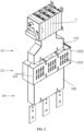
FIG. 1 is a schematic structural view of a fuse-switch-disconnector assembly according to a specific embodiment of the present application; -
FIG. 2 is a schematic structural view of a fuse-switch-disconnector according to a specific embodiment of the present application; -
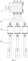
FIG. 3 is a schematic structural view of a fuse-switch-disconnector according to a specific embodiment of the present application, in which a protective box, a first protective shield and a second protective shield are not shown; -
FIG. 4 is a side view of a fuse assembly according to a specific embodiment of the present application; -
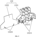
FIG. 5 is a schematic structural view of a first protective shield according to a specific embodiment of the present application which is not assembled; -
FIG. 6 is a schematic structural view of a second protective shield according to a specific embodiment of the present application which is not assembled; -
FIG. 7 is a schematic structural view of a fault indicator according to a specific embodiment of the present application being in a first state; -
FIG. 8 is a schematic structural view of a fault indicator according to a specific embodiment of the present application being in a second state. - Reference numerals in the drawings are listed as follows:
- 1 fuse-switch-disconnector;
- 11 isolating switch;
- 12 fuse assembly;
- 121 fuse;
- 122 protective box, 1221 vent, 1222 transparent window;
- 123 fault indicator;
- 13 connection copper bar assembly;
- 131 connection copper bar ;
- 132 first protective shield;
- 1321 first shield body, 13211 first guide groove, 13212 first buckle;
- 1322 first cover body, 13221 first limiting hole;
- 14 wiring copper bar assembly;
- 141 wiring copper bar;
- 142 second protective shield;
- 1421 second shield body, 14211 second guide groove, 14212 second buckle;
- 1422 second cover body, 14221 second limiting hole;
- 2 insulating partition plate.
- The embodiments of the present application are described in detail hereinafter, and examples of the embodiments are shown in drawings, in which the same or similar reference numerals represent the same or similar members or members having the same or similar functions throughout the description. The embodiments described below with reference to the drawings are only exemplary embodiments which are used to explain the present application, and should not be construed to limit the present application.
- In the description of the present application, it should be noted that, the terms "center", "upper", "lower", "left", "right", "vertical", "horizontal", "inner", "outer" and the like indicate the orientation or positional relationship based on the orientation or positional relationship shown in the drawings, and are only for the convenience of describing the present application and simplifying description, and do not indicate or imply that the device or element referred to must have a specific orientation, be constructed and operated in a specific orientation, therefore, the terms cannot be understood as a limitation of the present application. In addition, the terms "first", "second" and the like are for purpose of description, and should not be construed as indicating or implying relative importance. Terms "first position" and "second position" represent two different positions.
- In the description of the present application, unless otherwise clearly specified and limited, the terms "linked", "connected", and "fixed" shall be interpreted broadly, for example, may be interpreted as being fixedly connected, detachably connected, or integrated; the terms may be interpreted as being mechanically connected or electrically connected; the terms may also be interpreted as being directly connected or indirectly connected through an intermediate medium, and the terms may further be interpreted as internal communication between two components or interactional relationship between two components. Those skilled in the art may understand meanings of the foregoing terms in the present application according to specific conditions.
- In the present application, unless otherwise clearly defined and limited, a first feature being "above" or "below" a second feature may include situations that the first feature and the second feature are in contact with each other directly, or the first feature and the second feature are in contact with each other indirectly via another feature between them. Furthermore, the fact that the first feature is "above", "over" and "on" the second feature includes that the first feature is directly above and obliquely above the second feature, or simply indicates that the first feature is higher in horizontal height than the second feature. The fact that the first feature is "below", "under" and "down" the second feature includes that the first feature is directly below and obliquely below the second feature, or simply indicates that the first feature is lower in horizontal height than the second feature.
- Technical solutions of the present application will be further described through the embodiments and in conjoint with drawings.
- As shown in
FIG. 1 to FIG. 4 , a fuse-switch-disconnector assembly is disclosed in this embodiment, which includes at least one fuse-switch-disconnector 1. The fuse-switch-disconnector 1 includes an isolatingswitch 11 and afuse assembly 12 that are detachably connected with each other. Thefuse assembly 12 includes afuse 121 and aprotective box 122 for accommodating thefuse 121. Theprotective box 122 is provided with a heat dissipation channel for dissipating heat from thefuse 121, and theprotective box 122 is further provided with atransparent window 1222, by which the state of thefuse 121 can be observed. - First of all, compared with a circuit breaker, the
fuse 121 can quickly cut off the corresponding circuit to improve the safety of the circuit. Secondly, when a short-circuit fault occurs in a circuit, the isolatingswitch 11 detachably connected with thefuse assembly 12 manages to disconnect the circuit so as to directly replace thefuse assembly 12, thereby ensuring the safety of replacing thefuse assembly 12 and avoiding affecting the normal operation of other circuits, and dissipating the heat from thefuse 121 through the heat dissipation channel on theprotective box 122 to prolong the service life of thefuse 121 as much as possible. Finally, the state of thefuse 121 can be observed in time through thetransparent window 1222 to determine whether it is necessary to replace thefuse 121, and the visualization of the molded case circuit breaker may also be realized. The fuse-switch-disconnector assembly can ensure that the normal operation of other circuits will not be affected when thefuse 121 of a certain circuit is replaced. Moreover, the detachable connection between the isolatingswitch 11 and thefuse assembly 12 facilitates the replacement of thefuse assembly 12, and by means of thetransparent window 1222, thefuse 12 can be visualized and the state of thefuse 121 may be promptly observed. - Exemplarily, the
transparent window 1222 is arranged at a top end of theprotective box 122. - Considering the need of the replacement of the
fuse 121, theprotective box 122 is formed by splicing two half-protective shields to avoid a case that thewhole fuse assembly 12 have to be replaced, thereby reducing the maintenance cost. - In this embodiment, vents 1221 are arranged at two opposite side walls of the
protective box 122, respectively, to form heat dissipation channels, that is, thefuse 121 is located between the two vents, thereby ensuring the heat dissipation effect of thefuse 121. - Considering that the circuit is a three-phase alternating current circuit, as shown in
FIG. 3 , threefuses 121 are provided in onefuse assembly 12. The three fuses 121 are arranged in theprotective box 122 at intervals in a length direction of theprotective box 122 to correspond to phases A, B and C, respectively. - The two opposite side walls of the
protective box 122 are evenly provided withmultiple vents 1221 around eachfuse 121 to form multiple heat dissipation channels, thereby ensuring the heat dissipation effect to eachfuse 121 in theprotective box 122. - Similarly, the top end of the
protective box 122 is provided with threetransparent windows 1222 arranged at intervals in the length direction of theprotective box 122. The threetransparent windows 1222 correspond to the threefuses 121, respectively, and are located directly above the correspondingfuses 121 correspondingly, so as to accurately determine the failed fuses 121 among the three fuses 121. - In particular, as shown in
FIG. 3 , the fuse-switch-disconnector 1 further includes a connectioncopper bar assembly 13, which includes aconnection copper bar 131. Theconnection copper bar 131 is detachably connected with an input terminal of the isolatingswitch 11 and an output terminal of thefuse 121, respectively by bolts. Also, in other embodiments, other structures can be adopted to realize the detachable connection between the isolatingswitch 11 and thefuse 121, which will not be specifically limited in this embodiment. - It can be understood that the number of output terminals of the isolating
switch 11 is the same as the number of thefuses 121 in theprotective box 122. - Further, as shown in
FIG. 4 , the connectioncopper bar assembly 13 further includes a firstprotective shield 132 which abuts against a bottom end of the isolatingswitch 11 and a top end of theprotective box 122. The firstprotective shield 132 includes afirst shield body 1321 and afirst cover body 1322 which are detachably connected with each other, and a first accommodating groove which can accommodate the connection copper bars 131 is arranged in thefirst shield body 1321. Thefirst cover body 1322 may be snap-fitted with thefirst shield body 1321 and cover the first accommodating groove, thus realizing insulation protection from the input terminal of the isolatingswitch 11 to the output terminal of thefuse 121 and improving the use safety of the fuse-switch-disconnector 1. - In particular, the
first shield body 1321 is provided with twofirst guide grooves 13211 located on both sides of the first accommodating groove, one of thefirst shield body 1321 and thefirst cover body 1322 is provided with a first limitinghole 13221, and the other is provided with afirst buckle 13212 that can cooperate with the first limitinghole 13221. Thefirst cover body 1322 can slide along thefirst guide groove 13211 until thefirst buckle 13212 is clamped with the first limitinghole 13211 to enable thefirst cover body 1322 being engaged with thefirst shield body 1321. Similarly, when it is necessary to detach thefirst cover body 1322 from thefirst shield body 1321, it only needs to slide thefirst cover body 1322 in an opposite direction to detach thefirst buckle 13212 from the first limitinghole 13221. - Exemplarily, in order to ensure the stability of clamping, multiple first limiting
holes 13221 and correspondingfirst buckles 13212 are provided. - In this embodiment, the fuse-switch-
disconnector 1 further includes a wiringcopper bar assembly 14, which includes wiring copper bars 141. Thewiring copper bar 141 is detachably connected with an input terminal of thefuse 121 and an external cable, respectively. Also, in other embodiments, other structures can be adopted to realize the detachable connection between thefuse 121 and the external cable, which will not be specifically limited in this embodiment. - Referring to
FIG. 6 , the wiringcopper bar assembly 14 further includes a secondprotective shield 142 that can abut against the bottom end of theprotective box 122. The secondprotective shield 142 includes asecond shield body 1421 and asecond cover body 1422 that are detachably connected with each other, and a second accommodating groove that can accommodate thewiring copper bar 141 is arranged in thesecond shield body 1421. Thesecond cover body 1422 can be snap-fitted with thesecond shield body 1421 and cover the second accommodating groove, thus realizing insulation protection from the input terminal of thefuse 121 to the output terminal of the external cable and improving the use safety of the fuse-switch-disconnector 1. - In particular, the
second shield body 1421 is provided with twosecond guide grooves 14211 located on both sides of the second accommodating groove. One of thesecond shield body 1421 and thesecond cover body 1422 is provided with a second limitinghole 14221, and the other is provided with asecond buckle 14212 that can cooperate with the second limitinghole 14221. Thesecond cover body 1422 can slide along thesecond guide groove 14211 until thesecond buckle 14212 is clamped with the second limitinghole 14221 to enable thesecond cover body 1422 being engaged with thesecond shield body 1421. Similarly, when it is necessary to detach thesecond cover body 1422 from thesecond shield body 1421, it only needs to slide thesecond cover body 1422 in the opposite direction to detach thesecond buckle 14212 from the second limitinghole 14221. - Exemplarily, in order to ensure the stability of the clamping connection, multiple second limiting
holes 14221 and correspondingsecond buckles 14212 are provided. - As shown in
FIG. 7 , in order to facilitate the maintenance personnel to observe the state of thefuse 121 through the transparent windows 1222 (that is, whether a fuse wire of thefuse 121 is fused), thefuse assembly 12 further includes afault indicator 123 connected with thefuse 121, and thefuse 121 corresponds to thefault indicator 123 in one-to-one correspondence, so that the state of thefuse 121 may be judged by thefault indicator 123. - In particular, the
fault indicator 123 is an elastic sheet, one end of which is arranged at the top end of thefuse 121, and the other end of which is connected with the fuse wire. When the fuse wire is not fused, as shown inFIG. 7 , the elastic sheet is in a first state, that is, the elastic sheet is completely attached to the top end of thefuse 121. When the fuse wire is fused due to short circuit, as shown inFIG. 8 , the elastic sheet is in a second state, where one end of the elastic sheet connected with the fuse wire loses its fastening force due to the fuse wire being fused, which leads it to be away from thefuse 121, that is, this end of the elastic sheet is tilted compared with the top end of thefuse 121, so that the maintenance personnel can intuitively judge the state of thefuse 121. - In this embodiment, in order to control the states of the multiple circuits respectively, the fuse-switch-disconnector assembly includes multiple fuse-switch-
disconnectors 1, which are arranged at intervals in the width direction of theprotective box 122, so as to avoid the mutual interference of the heat dissipation channels of two adjacentprotective boxes 122 and ensure the heat dissipation effect on eachfuse 121 as much as possible. - The fuse-switch-disconnector assembly further includes an insulating
partition plate 2, and the insulatingpartition plate 2 abuts against the bottom end of each secondprotective shield 142 to separate the connection portion of the output terminal of the external cable from other portions of the fuse-switch-disconnector 1, so as to improve the safety as much as possible. - During operation, each backflow current is inputted from the external cable, passes through the corresponding
wiring copper bar 141,fuse 121,connection copper bar 131 and isolatingswitch 11 in sequence, and is converged on a bus bar. When a short-circuit fault occurs in a certain circuit, thefuse 121 corresponding to that circuit will be fused to protect the safety of the circuit, and thefault indicator 123 on thefuse 121 will pop up to indicate where the fault is. When the maintenance personnel carry out the maintenance, the specific position of thefault fuse 121 may be judged through thetransparent window 1222 on theprotective box 122, the connection between the circuit and the bus bar can be cut off by rotating a handle of the isolatingswitch 11 corresponding to the circuit, and the firstprotective shield 132 and the secondprotective shield 1422 can be quickly disassembled by sliding thefirst cover body 1322 and thesecond cover body 1422 respectively, so that the bolts can be loosened to take out thefuse assembly 12 as a whole for subsequent replacement. - The above contents are only the preferred embodiments of the present application. According to the idea of the present application, there will be some changes in the specific implementation and application scope for those skilled in the art, and the contents of this specification should not be understood as limitations to the present application.
Claims (12)
- A fuse-switch-disconnector assembly, comprising at least one fuse-switch-disconnector (1), wherein the fuse-switch-disconnector (1) comprises an isolating switch (11) and a fuse assembly (12) that are detachably connected with each other, the fuse assembly (12) comprises a fuse (121) and a protective box (122) for accommodating the fuse (121), the protective box (122) is provided with a heat dissipation channel that dissipates heat from the fuse (121), wherein the protective box (122) is further provided with a transparent window, a state of the fuse (121) is observed through the transparent window.
- The fuse-switch-disconnector assembly according to claim 1, wherein three fuses (121) are provided in one fuse assembly (12), which are arranged in the protective box (122) at intervals in a length direction of the protective box (122).
- The fuse-switch-disconnector assembly according to claim 1, wherein the fuse-switch-disconnector (1) further comprises a connection copper bar assembly (13), the connection copper bar assembly (13) comprises a connection copper bar (131) that is detachably connected with an input terminal of the isolating switch (11) and an output terminal of the fuse (121), respectively.
- The fuse-switch-disconnector assembly according to claim 3, wherein the connection copper bar assembly (13) further comprises a first protective shield (132) which abuts against a bottom end of the isolating switch (11) and a top end of the protective box (122), respectively, the first protective shield (132) comprises a first shield body (1321) and a first cover body (1322) that are detachably connected with each other, wherein the first shield body (1321) is provided with a first accommodating groove inside, which is capable of accommodating the connection copper bar (131), and the first cover body (1322) is snap-fitted with the first shield body (1321) and covers the first accommodating groove.
- The fuse-switch-disconnector assembly according to claim 4, wherein the first shield body (1321) is provided with two first guide grooves (13211), which are located at both sides of the first accommodating groove, respectively, one of the first shield body (1321) and the first cover body (1322) is provided with a first limiting hole (13221), and the other of the first shield body (1321) and the first cover body (1322) is provided with a first buckle (13212) that is matched with the first limiting hole (13221), and the first cover body (1322) slides along the first guide groove (13211) until the first buckle (13212) is clamped with the first limiting hole (13221) so as to enable the first cover body (1322) being engaged with the first shield body (1321).
- The fuse-switch-disconnector assembly according to claim 1, wherein the fuse-switch-disconnector (1) further comprises a connection copper bar assembly (14), and the connection copper bar assembly (14) comprises a connection copper bar (141) that is detachably connected with an input terminal of the fuse (121) and an external cable, respectively.
- The fuse-switch-disconnector assembly according to claim 6, wherein the connection copper bar assembly (14) further comprises a second protective shield (142) that abuts against the bottom end of the protective box (122), and the second protective shield (142) comprises a second shield body (1421) and a second cover body (1422) that are detachably connected with each other, wherein the second shield body (1421) is provided with a second accommodating groove inside, which accommodates the connection copper bar (141), and the second cover body (1422) is snap-fitted with the second shield body (1421) and covers the second accommodating groove..
- The fuse-switch-disconnector assembly according to claim 7, wherein the second shield body (1421) is provided with two second guide grooves (14211) located at both sides of the second accommodating groove, respectively, one of the second shield body (1421) and the second cover body (1422) is provided with a second limiting hole (14221), and the other of the second shield body (1421) and the second cover body (1422) is provided with a second buckle (14212) that is matched with the second limiting hole (14221), and the second cover body (1422) slides along the second guide groove (14211) until the second buckle (14212) is clamped with the second limiting hole (14221) so as to enable the second cover body (1422) being engaged with the second shield body (1421).
- The fuse-switch-disconnector assembly according to claim 1, wherein the fuse assembly (12) further comprises a fault indicator (123) connected with the fuse (121), and the fuse (121) corresponds to the fault indicator (123) in one-to-one correspondence, and a state of the fuse (121) is judged by the fault indicator (123).
- The fuse-switch-disconnector assembly according to claim 1, wherein two opposite side walls of the protective box (122) are both provided with vents (1221) to form heat dissipation channels.
- The fuse-switch-disconnector assembly according to claim 10, wherein the two opposite side walls of the protective box (122) are both provided with a plurality of vents (1221) around the fuse (121) to form a plurality of heat dissipation channels.
- The fuse-switch-disconnector assembly according to any one of claims 1 to 11, wherein a plurality of sets of fuse-switch-disconnector (1) are arranged at intervals in a width direction of the protective box (122).
Applications Claiming Priority (2)
| Application Number | Priority Date | Filing Date | Title |
|---|---|---|---|
| CN202122138159.8U CN216213246U (en) | 2021-09-06 | 2021-09-06 | Isolating switch fuse assembly |
| PCT/CN2022/095224 WO2023029614A1 (en) | 2021-09-06 | 2022-05-26 | Fuse-switch-disconnector assembly |
Publications (2)
| Publication Number | Publication Date |
|---|---|
| EP4339991A1 true EP4339991A1 (en) | 2024-03-20 |
| EP4339991A4 EP4339991A4 (en) | 2025-04-23 |
Family
ID=80918199
Family Applications (1)
| Application Number | Title | Priority Date | Filing Date |
|---|---|---|---|
| EP22862756.8A Pending EP4339991A4 (en) | 2021-09-06 | 2022-05-26 | Arrangement for isolating a circuit breaker |
Country Status (3)
| Country | Link |
|---|---|
| EP (1) | EP4339991A4 (en) |
| CN (1) | CN216213246U (en) |
| WO (1) | WO2023029614A1 (en) |
Families Citing this family (1)
| Publication number | Priority date | Publication date | Assignee | Title |
|---|---|---|---|---|
| CN216213246U (en) * | 2021-09-06 | 2022-04-05 | 阳光电源股份有限公司 | Isolating switch fuse assembly |
Family Cites Families (9)
| Publication number | Priority date | Publication date | Assignee | Title |
|---|---|---|---|---|
| DE3126500A1 (en) * | 1981-07-04 | 1983-01-20 | Lindner Gmbh, Fabrik Elektrischer Lampen Und Apparate, 8600 Bamberg | Fuse-link load switch |
| FI104522B (en) * | 1998-04-28 | 2000-02-15 | Abb Control Oy | Fused switch |
| JP2010263685A (en) * | 2009-05-01 | 2010-11-18 | Fujikura Ltd | Heat dissipation member and electrical junction box |
| CN202855686U (en) * | 2012-09-13 | 2013-04-03 | 常州瑞联电力科技有限公司 | Switching device for strip-shaped fuse |
| CN202917421U (en) * | 2012-11-29 | 2013-05-01 | 周海兵 | Novel fuse-type isolating switch |
| CN105845525B (en) * | 2015-01-16 | 2018-11-13 | 西门子公司 | The radiator and its fuse switch of fuse switch |
| CN204315441U (en) * | 2015-01-26 | 2015-05-06 | 浙江茗熔电器保护系统有限公司 | Combined fuse-type isolating switch |
| CN209607655U (en) * | 2018-12-29 | 2019-11-08 | 浙江乾茂电气科技有限公司 | A kind of fuse disconnecting switch |
| CN216213246U (en) * | 2021-09-06 | 2022-04-05 | 阳光电源股份有限公司 | Isolating switch fuse assembly |
-
2021
- 2021-09-06 CN CN202122138159.8U patent/CN216213246U/en active Active
-
2022
- 2022-05-26 EP EP22862756.8A patent/EP4339991A4/en active Pending
- 2022-05-26 WO PCT/CN2022/095224 patent/WO2023029614A1/en not_active Ceased
Also Published As
| Publication number | Publication date |
|---|---|
| WO2023029614A1 (en) | 2023-03-09 |
| CN216213246U (en) | 2022-04-05 |
| EP4339991A4 (en) | 2025-04-23 |
Similar Documents
| Publication | Publication Date | Title |
|---|---|---|
| CA2723661C (en) | Configurable deadfront fusible panelboard | |
| EP3062403B1 (en) | Gas-insulated switchgear | |
| KR101343512B1 (en) | Distribution system with individually blockable functional areas | |
| EP3667690B1 (en) | Molded case circuit breaker | |
| CN101242082B (en) | Direct current circuit switchboard with commutation-type direct current breaker | |
| US20240258731A1 (en) | Enclosure and Optimizations | |
| US11670899B2 (en) | Current bar module and corresponding connection module | |
| WO2016144610A1 (en) | High voltage compact fusible disconnect switch device with magnetic arc deflection assembly | |
| ZA200605330B (en) | Handle apparatus and electrical switching apparatus employing the same | |
| KR20170034666A (en) | Receive connector and connector assembly | |
| CN216213246U (en) | Isolating switch fuse assembly | |
| EP3280016B1 (en) | Gas-insulated switchgear | |
| CN116157973A (en) | switchboard | |
| KR102788607B1 (en) | Air circuit breaker having insulation paper to prevent terminal short circuit | |
| US20080030930A1 (en) | Supply System for Low-Voltage Switchgear | |
| KR102467791B1 (en) | Cuicuit Breaker having Main Circuit Part Cover | |
| CN112821206B (en) | Enclosed bus structure of power distribution electric appliance | |
| CN221994410U (en) | Terminal cover | |
| CN223155898U (en) | Isolation structure of switch electric appliance and fusing type isolation switch | |
| EP2144342B1 (en) | Drawout door interface for circuit breaker | |
| CN210349724U (en) | Switch electric appliance | |
| KR200398669Y1 (en) | Harness cable for distribution switchboard | |
| US20220077664A1 (en) | Switching and/or Distributing Device | |
| CN205645667U (en) | Heavy current high pressure vacuum circuit breaker and aerify cabinet | |
| HK1225521B (en) | Gas-insulated switchgear |
Legal Events
| Date | Code | Title | Description |
|---|---|---|---|
| STAA | Information on the status of an ep patent application or granted ep patent |
Free format text: STATUS: THE INTERNATIONAL PUBLICATION HAS BEEN MADE |
|
| PUAI | Public reference made under article 153(3) epc to a published international application that has entered the european phase |
Free format text: ORIGINAL CODE: 0009012 |
|
| STAA | Information on the status of an ep patent application or granted ep patent |
Free format text: STATUS: REQUEST FOR EXAMINATION WAS MADE |
|
| 17P | Request for examination filed |
Effective date: 20231214 |
|
| AK | Designated contracting states |
Kind code of ref document: A1 Designated state(s): AL AT BE BG CH CY CZ DE DK EE ES FI FR GB GR HR HU IE IS IT LI LT LU LV MC MK MT NL NO PL PT RO RS SE SI SK SM TR |
|
| DAV | Request for validation of the european patent (deleted) | ||
| DAX | Request for extension of the european patent (deleted) | ||
| A4 | Supplementary search report drawn up and despatched |
Effective date: 20250326 |
|
| RIC1 | Information provided on ipc code assigned before grant |
Ipc: H01H 71/02 20060101ALI20250320BHEP Ipc: H01H 85/20 20060101ALI20250320BHEP Ipc: H01H 85/47 20060101ALI20250320BHEP Ipc: H01H 89/00 20060101AFI20250320BHEP |