EP4339967A1 - Nuclear-based heat and power for low-earth orbit (leo) and deep space missions - Google Patents
Nuclear-based heat and power for low-earth orbit (leo) and deep space missions Download PDFInfo
- Publication number
- EP4339967A1 EP4339967A1 EP23197487.4A EP23197487A EP4339967A1 EP 4339967 A1 EP4339967 A1 EP 4339967A1 EP 23197487 A EP23197487 A EP 23197487A EP 4339967 A1 EP4339967 A1 EP 4339967A1
- Authority
- EP
- European Patent Office
- Prior art keywords
- reactor
- coolant
- recited
- fuel rods
- heat exchange
- Prior art date
- Legal status (The legal status is an assumption and is not a legal conclusion. Google has not performed a legal analysis and makes no representation as to the accuracy of the status listed.)
- Pending
Links
Images


Classifications
-
- G—PHYSICS
- G21—NUCLEAR PHYSICS; NUCLEAR ENGINEERING
- G21H—OBTAINING ENERGY FROM RADIOACTIVE SOURCES; APPLICATIONS OF RADIATION FROM RADIOACTIVE SOURCES, NOT OTHERWISE PROVIDED FOR; UTILISING COSMIC RADIATION
- G21H1/00—Arrangements for obtaining electrical energy from radioactive sources, e.g. from radioactive isotopes, nuclear or atomic batteries
-
- B—PERFORMING OPERATIONS; TRANSPORTING
- B64—AIRCRAFT; AVIATION; COSMONAUTICS
- B64G—COSMONAUTICS; VEHICLES OR EQUIPMENT THEREFOR
- B64G1/00—Cosmonautic vehicles
- B64G1/22—Parts of, or equipment specially adapted for fitting in or to, cosmonautic vehicles
- B64G1/42—Arrangements or adaptations of power supply systems
- B64G1/421—Non-solar power generation
- B64G1/422—Nuclear power generation
-
- B—PERFORMING OPERATIONS; TRANSPORTING
- B64—AIRCRAFT; AVIATION; COSMONAUTICS
- B64G—COSMONAUTICS; VEHICLES OR EQUIPMENT THEREFOR
- B64G1/00—Cosmonautic vehicles
- B64G1/22—Parts of, or equipment specially adapted for fitting in or to, cosmonautic vehicles
- B64G1/52—Protection, safety or emergency devices; Survival aids
- B64G1/58—Thermal protection, e.g. heat shields
-
- G—PHYSICS
- G21—NUCLEAR PHYSICS; NUCLEAR ENGINEERING
- G21C—NUCLEAR REACTORS
- G21C15/00—Cooling arrangements within the pressure vessel containing the core; Selection of specific coolants
- G21C15/02—Arrangements or disposition of passages in which heat is transferred to the coolant; Coolant flow control devices
-
- G—PHYSICS
- G21—NUCLEAR PHYSICS; NUCLEAR ENGINEERING
- G21D—NUCLEAR POWER PLANT
- G21D5/00—Arrangements of reactor and engine in which reactor-produced heat is converted into mechanical energy
- G21D5/02—Reactor and engine structurally combined, e.g. portable
-
- G—PHYSICS
- G21—NUCLEAR PHYSICS; NUCLEAR ENGINEERING
- G21D—NUCLEAR POWER PLANT
- G21D7/00—Arrangements for direct production of electric energy from fusion or fission reactions
- G21D7/04—Arrangements for direct production of electric energy from fusion or fission reactions using thermoelectric elements or thermoionic converters
-
- Y—GENERAL TAGGING OF NEW TECHNOLOGICAL DEVELOPMENTS; GENERAL TAGGING OF CROSS-SECTIONAL TECHNOLOGIES SPANNING OVER SEVERAL SECTIONS OF THE IPC; TECHNICAL SUBJECTS COVERED BY FORMER USPC CROSS-REFERENCE ART COLLECTIONS [XRACs] AND DIGESTS
- Y02—TECHNOLOGIES OR APPLICATIONS FOR MITIGATION OR ADAPTATION AGAINST CLIMATE CHANGE
- Y02E—REDUCTION OF GREENHOUSE GAS [GHG] EMISSIONS, RELATED TO ENERGY GENERATION, TRANSMISSION OR DISTRIBUTION
- Y02E30/00—Energy generation of nuclear origin
- Y02E30/30—Nuclear fission reactors
Definitions
- the present disclosure relates to long service-life power sources, and more particularly to nuclear-based heat and power sources such as for low-earth orbit (LEO) and deep space missions.
- LEO low-earth orbit
- Deep-space missions and low earth orbit (LEO) missions require long-term supplies of heat and electric power.
- Heat is needed to support the endothermic reactions such as Sabatier reactions, regeneration, and the like.
- Electricity is required for power electronic devices carried onboard spacecraft and space-borne devices such as satellites.
- a system includes a nuclear reactor having a plurality of fuel rods of radioactive decay material distributed within and embedded within a heat exchange matrix.
- a plurality of coolant tubes are distributed within and embedded within the heat exchange matrix, interspersed with the plurality of fuel rods.
- the heat exchange matrix is configured to conduct heat from the fuel rods to the coolant tubes.
- the heat exchange matrix can be of graphite.
- the nuclear reactor can be cylindrical defining an axis, wherein the plurality of fuel rods and the plurality of the cooling tubes are aligned with the axis.
- An inner shroud can house the plurality of fuel rods, the plurality of coolant tubes, and the heat exchange matrix.
- a plurality of structural supports can extend outward from the inner shroud.
- An outer shroud can be connected to the plurality of structural supports for supporting the inner shroud within the outer shroud.
- Thermal insulation material can fill or can be seated in pockets defined between the inner and outer shrouds.
- An outer radiation shield can line an outer surface of the outer shroud. Zirconia clad tubing can line between each of the fuel rods and the heat exchange matrix.
- a first one of the cooling tubes can be an inlet tube that communicates out of the reactor for passage of coolant outside the reactor into the reactor.
- a second one of the cooling tubes can be an outlet tube that communicates out of the reactor for passage of coolant inside the reactor out of the reactor.
- a thermoelectric generator (TEG) can be in fluid communication with the outlet tube for receiving coolant from the reactor and in fluid communication with the inlet tube for return of coolant to the reactor.
- the TEG can be configured to convert heat energy from coolant from the reactor into electrical power.
- a pump in the inlet tube or the outlet tube can be included for driving a flow of coolant through the coolant tubes and TEG.
- a battery can be electrically connected to the TEG to charge the battery.
- the pump can be electrically connected to the battery for powering the pump.
- Coolant can be included in a closed circuit within the plurality of coolant tubes in the reactor and TEG.
- a crewed or uncrewed spacecraft can be included as part of the system.
- the spacecraft can include at least one power electronics system connected to the battery for electrical power, and at least one heat dependent system in thermal communication with at least one of the inlet and outlet tubes for heating.
- Fig. 1 a partial view of an embodiment of a system in accordance with the disclosure is shown in Fig. 1 and is designated generally by reference character 100.
- Other embodiments of systems in accordance with the disclosure, or aspects thereof, are provided in Figs. 2-3 , as will be described.
- the systems and methods described herein can be used to provide heat and electrical power to spacecraft such as used for long term missions, low-earth orbit (LEO), and deep space missions such as to the Moon, Mars, and beyond.
- LEO low-earth orbit
- the system 100 includes a nuclear reactor 102 having a plurality of fuel rods 104 of radioactive decay material, e.g., with a half-life selected for the desired duration of the intended spacecraft mission.
- the fuel rods 104 are distributed within and embedded within a heat exchange matrix 106.
- a plurality of coolant tubes 108 e.g., of stainless steel, are distributed within and embedded within the heat exchange matrix 106, interspersed with the plurality of fuel rods 104.
- the fuel rods (see Fig. 4 for different types of radioactive isotopes that could be used in the reactor 102) are tubes made of zirconium dioxide (ZrO2), called zircalloy, which houses the radioactive material. As shown in Fig.
- the radioactive isotope material is typically used in an oxide form (i.e., ceramic material) with a higher melting point compared to the metal itself.
- Cm 2 244 O 2 has melting point of 3,956 °F ( ⁇ 2,000 °C), density of 9 g/cc, and specific power of 2.27 W th /g.
- the heat exchange matrix 106 is of a graphite material, or any other suitable material configured to conduct heat from the fuel rods 104 to the coolant tubes 108.
- An inner cylindrical shroud 110 houses the plurality of fuel rods 104, the plurality of coolant tubes 108, and the heat exchange matrix 106.
- Thermal insulation material 116 e.g., of Al 2 O 3 , MgO, or the like, fills or is seated in pockets defined radially between the inner and outer shrouds 110, 114, wherein the pockets are circumferentially between adjacent pairs of the structural supports 112.
- the insulation material 116 resists heat losses out of the inner core 110.
- An outer radiation shield 118 e.g. of lead, lines an outer surface of the outer shroud 114.
- Zirconia (ZrO 2 ) clad tubing 120 lines between each of the fuel rods 104 and the heat exchange matrix 106.
- the nuclear reactor 102 is cylindrical defining a cylinder axis A.
- the plurality of fuel rods 104 and the plurality of the cooling tubes 108 are aligned parallel with the axis A.
- the fuel rods 104 are not shown in Fig. 2 , but they can be coextensive in the axial direction with the cooling tubes 108.
- a first one of the cooling tubes is an inlet tube 122 that communicates out of the reactor 102 for passage of coolant outside the reactor 102 flowing into the reactor 102.
- a second one of the cooling tubes is an outlet tube 124 that communicates out of the reactor 102 for passage of coolant inside the reactor 102 flowing out of the reactor 102.
- the other coolant tubes 108 can be interconnected for flow through the reactor 102 between the inlet tube 122 and the outlet tube 124.
- thermoelectric generator (TEG) 126 is in fluid communication with the outlet tube 124 for receiving heated coolant from the reactor 102 and in fluid communication with the inlet tube 122 for return of cooled coolant to the reactor 102.
- the TEG is configured to convert heat energy from coolant from the reactor 102 into electrical power.
- a pump 128 is included in the inlet tube 122 and/or the outlet tube 124 for circulating a flow of coolant, i.e., heat transfer medium, through the coolant tubes 108 and TEG 126.
- a battery 130 is electrically connected, e.g. in electrical line 136, to the TEG 126 to charge the battery 130 with electrical power from the TEG 126.
- the pump(s) 128 is/are electrically connected, as indicated by the dashed lines in Fig. 3 ) to the battery 130 for powering the pump(s) 128.
- Coolant such as helium gas (He), carbon dioxide gas (CO 2 ), or liquid, is in a closed circuit within the plurality of coolant tubes 108 in the reactor 102 and TEG 126.
- a manned or unmanned spacecraft 10 is included.
- the spacecraft 10 includes at least one power electronics system 132 connected to the battery 130, e.g. by electrical line 136, for electrical power.
- At least one heat dependent system 134 of the spacecraft 10 is/are in thermal communication with at least one of the inlet and outlet tubes 124, 122 for heating.
- Heat dependent systems 134 can include a Sabatier reactor which combines H 2 and CO 2 to produce H 2 O and Methane (CH 4 ), which methane can thermally decompose to H 2 and solid carbon powder. They can also include any other suitable devices, such as devices to regenerate solid thermal amine scrubbers (TAS), and the like.
- Systems and methods as disclosed herein integrate a nuclear heat generator (NHG) with a thermoelectric generator (TEG) to provide long-term heat and electricity for spacecraft designed for long-term missions in deep space or low-earth orbit (LEO).
- the nuclear fuel type can be tailored to the mission, e.g. by matching a suitable half-life (t 1/2 ) to the anticipated mission duration.
Landscapes
- Engineering & Computer Science (AREA)
- Physics & Mathematics (AREA)
- High Energy & Nuclear Physics (AREA)
- General Engineering & Computer Science (AREA)
- Plasma & Fusion (AREA)
- Remote Sensing (AREA)
- Aviation & Aerospace Engineering (AREA)
- Chemical Kinetics & Catalysis (AREA)
- Chemical & Material Sciences (AREA)
- Thermal Sciences (AREA)
- Health & Medical Sciences (AREA)
- Critical Care (AREA)
- Emergency Medicine (AREA)
- General Health & Medical Sciences (AREA)
- Life Sciences & Earth Sciences (AREA)
- Sustainable Development (AREA)
- Heat-Exchange Devices With Radiators And Conduit Assemblies (AREA)
Abstract
Description
- The present disclosure relates to long service-life power sources, and more particularly to nuclear-based heat and power sources such as for low-earth orbit (LEO) and deep space missions.
- Deep-space missions and low earth orbit (LEO) missions require long-term supplies of heat and electric power. Heat is needed to support the endothermic reactions such as Sabatier reactions, regeneration, and the like. Electricity is required for power electronic devices carried onboard spacecraft and space-borne devices such as satellites.
- The conventional techniques have been considered satisfactory for their intended purpose. However, there is an ever-present need for improved systems and methods for powering spacecraft and space-borne devices. This disclosure provides a solution for this need.
- A system includes a nuclear reactor having a plurality of fuel rods of radioactive decay material distributed within and embedded within a heat exchange matrix. A plurality of coolant tubes are distributed within and embedded within the heat exchange matrix, interspersed with the plurality of fuel rods. The heat exchange matrix is configured to conduct heat from the fuel rods to the coolant tubes.
- The heat exchange matrix can be of graphite. The nuclear reactor can be cylindrical defining an axis, wherein the plurality of fuel rods and the plurality of the cooling tubes are aligned with the axis.
- An inner shroud can house the plurality of fuel rods, the plurality of coolant tubes, and the heat exchange matrix. A plurality of structural supports can extend outward from the inner shroud. An outer shroud can be connected to the plurality of structural supports for supporting the inner shroud within the outer shroud. Thermal insulation material can fill or can be seated in pockets defined between the inner and outer shrouds. An outer radiation shield can line an outer surface of the outer shroud. Zirconia clad tubing can line between each of the fuel rods and the heat exchange matrix.
- A first one of the cooling tubes can be an inlet tube that communicates out of the reactor for passage of coolant outside the reactor into the reactor. A second one of the cooling tubes can be an outlet tube that communicates out of the reactor for passage of coolant inside the reactor out of the reactor. A thermoelectric generator (TEG) can be in fluid communication with the outlet tube for receiving coolant from the reactor and in fluid communication with the inlet tube for return of coolant to the reactor. The TEG can be configured to convert heat energy from coolant from the reactor into electrical power. A pump in the inlet tube or the outlet tube can be included for driving a flow of coolant through the coolant tubes and TEG. A battery can be electrically connected to the TEG to charge the battery. The pump can be electrically connected to the battery for powering the pump. Coolant can be included in a closed circuit within the plurality of coolant tubes in the reactor and TEG.
- A crewed or uncrewed spacecraft can be included as part of the system. The spacecraft can include at least one power electronics system connected to the battery for electrical power, and at least one heat dependent system in thermal communication with at least one of the inlet and outlet tubes for heating.
- These and other features of the systems and methods of the subject disclosure will become more readily apparent to those skilled in the art from the following detailed description of the preferred embodiments taken in conjunction with the drawings.
- So that those skilled in the art to which the subject disclosure appertains will readily understand how to make and use the devices and methods of the subject disclosure without undue experimentation, preferred embodiments thereof will be described in detail herein below with reference to certain figures, wherein:
-
Fig. 1 is a schematic cross-sectional end elevation view of an embodiment of a system constructed in accordance with the present disclosure, showing the reactor; -
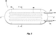
Fig. 2 is a schematic side elevation view of the system ofFig. 1 , showing the axis of the cylinder defined by the reactor; and -
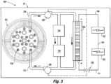
Fig. 3 is a schematic view of the system ofFig. 1 , showing spacecraft systems operatively connected to the reactor for heat and electrical power. -
Fig. 4 is a list of candidate radioisotopes, and their properties, for the nuclear heat generator (NHG). - Reference will now be made to the drawings wherein like reference numerals identify similar structural features or aspects of the subject disclosure. For purposes of explanation and illustration, and not limitation, a partial view of an embodiment of a system in accordance with the disclosure is shown in
Fig. 1 and is designated generally byreference character 100. Other embodiments of systems in accordance with the disclosure, or aspects thereof, are provided inFigs. 2-3 , as will be described. The systems and methods described herein can be used to provide heat and electrical power to spacecraft such as used for long term missions, low-earth orbit (LEO), and deep space missions such as to the Moon, Mars, and beyond. - The
system 100 includes anuclear reactor 102 having a plurality offuel rods 104 of radioactive decay material, e.g., with a half-life selected for the desired duration of the intended spacecraft mission. Thefuel rods 104 are distributed within and embedded within aheat exchange matrix 106. A plurality ofcoolant tubes 108, e.g., of stainless steel, are distributed within and embedded within theheat exchange matrix 106, interspersed with the plurality offuel rods 104. The fuel rods (seeFig. 4 for different types of radioactive isotopes that could be used in the reactor 102) are tubes made of zirconium dioxide (ZrO2), called zircalloy, which houses the radioactive material. As shown inFig. 4 , the radioactive isotope material is typically used in an oxide form (i.e., ceramic material) with a higher melting point compared to the metal itself. For example,
heat exchange matrix 106 is of a graphite material, or any other suitable material configured to conduct heat from thefuel rods 104 to thecoolant tubes 108. - An inner
cylindrical shroud 110, e.g., of stainless steel, houses the plurality offuel rods 104, the plurality ofcoolant tubes 108, and theheat exchange matrix 106. A plurality ofstructural supports 112, e.g., also of stainless steel, extend outward from theinner shroud 110. An outercylindrical shroud 114, e.g., also of stainless steel, is connected to the plurality ofstructural supports 112 for supporting theinner shroud 110 within theouter shroud 114.Thermal insulation material 116, e.g., of Al2O3, MgO, or the like, fills or is seated in pockets defined radially between the inner andouter shrouds structural supports 112. Theinsulation material 116 resists heat losses out of theinner core 110. An outer radiation shield 118, e.g. of lead, lines an outer surface of theouter shroud 114. Zirconia (ZrO2)clad tubing 120 lines between each of thefuel rods 104 and theheat exchange matrix 106. - With reference now to
Fig. 2 , thenuclear reactor 102 is cylindrical defining a cylinder axis A. The plurality offuel rods 104 and the plurality of thecooling tubes 108 are aligned parallel with the axis A. For sake of clarity in the drawings, thefuel rods 104 are not shown inFig. 2 , but they can be coextensive in the axial direction with thecooling tubes 108. A first one of the cooling tubes is aninlet tube 122 that communicates out of thereactor 102 for passage of coolant outside thereactor 102 flowing into thereactor 102. A second one of the cooling tubes is anoutlet tube 124 that communicates out of thereactor 102 for passage of coolant inside thereactor 102 flowing out of thereactor 102. Theother coolant tubes 108 can be interconnected for flow through thereactor 102 between theinlet tube 122 and theoutlet tube 124. - With reference now to
Fig. 3 , a thermoelectric generator (TEG) 126 is in fluid communication with theoutlet tube 124 for receiving heated coolant from thereactor 102 and in fluid communication with theinlet tube 122 for return of cooled coolant to thereactor 102. The TEG is configured to convert heat energy from coolant from thereactor 102 into electrical power. Apump 128 is included in theinlet tube 122 and/or theoutlet tube 124 for circulating a flow of coolant, i.e., heat transfer medium, through thecoolant tubes 108 andTEG 126. Abattery 130 is electrically connected, e.g. inelectrical line 136, to theTEG 126 to charge thebattery 130 with electrical power from theTEG 126. The pump(s) 128 is/are electrically connected, as indicated by the dashed lines inFig. 3 ) to thebattery 130 for powering the pump(s) 128. Coolant, such as helium gas (He), carbon dioxide gas (CO2), or liquid, is in a closed circuit within the plurality ofcoolant tubes 108 in thereactor 102 andTEG 126. - A manned or
unmanned spacecraft 10 is included. Thespacecraft 10 includes at least onepower electronics system 132 connected to thebattery 130, e.g. byelectrical line 136, for electrical power. At least one heatdependent system 134 of thespacecraft 10 is/are in thermal communication with at least one of the inlet andoutlet tubes dependent systems 134 can include a Sabatier reactor which combines H2 and CO2 to produce H2O and Methane (CH4), which methane can thermally decompose to H2 and solid carbon powder. They can also include any other suitable devices, such as devices to regenerate solid thermal amine scrubbers (TAS), and the like. - Potential benefits are now described. Systems and methods as disclosed herein integrate a nuclear heat generator (NHG) with a thermoelectric generator (TEG) to provide long-term heat and electricity for spacecraft designed for long-term missions in deep space or low-earth orbit (LEO). The nuclear fuel type can be tailored to the mission, e.g. by matching a suitable half-life (t1/2) to the anticipated mission duration.
- The methods and systems of the present disclosure, as described above and shown in the drawings, provide for heat and electrical power to spacecraft such as those used for long term missions, low-earth orbit, and deep space. While the apparatus and methods of the subject disclosure have been shown and described with reference to preferred embodiments, those skilled in the art will readily appreciate that changes and/or modifications may be made thereto without departing from the scope of the invention as defined by the claims.
Claims (15)
- A system comprising:
a nuclear reactor (102) comprising:a plurality of fuel rods (104) of radioactive decay material distributed within and embedded within a heat exchange matrix (106); anda plurality of coolant tubes (108) distributed within and embedded within the heat exchange matrix, interspersed with the plurality of fuel rods, wherein the heat exchange matrix is configured to conduct heat from the fuel rods to the coolant tubes. - The system as recited in claim 1, wherein the heat exchange matrix is of comprised of graphite.
- The system as recited in claim 1 or 2, further comprising an inner shroud (110) housing the plurality of fuel rods, the plurality of coolant tubes, and the heat exchange matrix.
- The system as recited in claim 3, further comprising a plurality of structural supports (112) extending outward from the inner shroud.
- The system as recited in claim 4, further comprising an outer shroud (114) connected to the plurality of structural supports for supporting the inner shroud within the outer shroud.
- The system as recited in claim 5, further comprising thermal insulation material (116) filling pockets defined between the inner and outer shrouds.
- The system as recited in claim 6, further comprising an outer radiation shield (118) lining an outer surface of the outer shroud.
- The system as recited in claim 7, further comprising Zirconia (ZrO2) clad tubing (120) lining between each of the fuel rods and the heat exchange matrix.
- The system as recited in any preceding claim, wherein the nuclear reactor (102) is cylindrical defining an axis, and wherein the plurality of fuel rods (104) and the plurality of the cooling tubes (108) are aligned with the axis.
- The system as recited in claim 9, wherein a first one of the cooling tubes is an inlet tube (122) that communicates out of the reactor for passage of coolant outside the reactor into the reactor, wherein a second one of the cooling tubes is an outlet tube (124) that communicates out of the reactor for passage of coolant inside the reactor out of the reactor.
- The system as recited in claim 10, further comprising a thermoelectric generator, TEG, (126) in fluid communication with the outlet tube for receiving coolant from the reactor and in fluid communication with the inlet tube for return of coolant to the reactor, wherein the TEG is configured to convert heat energy from coolant from the reactor into electrical power.
- The system as recited in claim 11, further comprising a pump (128) in the inlet tube or the outlet tube for driving a flow of coolant through the coolant tubes and TEG.
- The system as recited in claim 12, further comprising a battery (130) electrically connected to the TEG to charge the battery, wherein the pump is electrically connected to the battery for powering the pump.
- The system as recited in claim 13, further comprising coolant in a closed circuit within the plurality of coolant tubes in the reactor and TEG.
- A crewed or uncrewed spacecraft, comprising:a nuclear reactor (102) including:a plurality of fuel rods (104) of radioactive decay material distributed within and embedded within a heat exchange matrix (106);a plurality of coolant tubes (108) distributed within and embedded within the heat exchange matrix, interspersed with the plurality of fuel rods, wherein the heat exchange matrix is configured to conduct heat from the fuel rods to the coolant tubes; andat least one power electronics system (132) connected to a battery (130) for electrical power, and at least one heat dependent system in thermal communication with at least one of the inlet and outlet tubes for heating.
Applications Claiming Priority (1)
| Application Number | Priority Date | Filing Date | Title |
|---|---|---|---|
| US17/944,861 US12397934B2 (en) | 2022-09-14 | 2022-09-14 | Nuclear-based heat and power for low-earth orbit (LEO) and deep space missions |
Publications (1)
| Publication Number | Publication Date |
|---|---|
| EP4339967A1 true EP4339967A1 (en) | 2024-03-20 |
Family
ID=88068424
Family Applications (1)
| Application Number | Title | Priority Date | Filing Date |
|---|---|---|---|
| EP23197487.4A Pending EP4339967A1 (en) | 2022-09-14 | 2023-09-14 | Nuclear-based heat and power for low-earth orbit (leo) and deep space missions |
Country Status (2)
| Country | Link |
|---|---|
| US (1) | US12397934B2 (en) |
| EP (1) | EP4339967A1 (en) |
Citations (4)
| Publication number | Priority date | Publication date | Assignee | Title |
|---|---|---|---|---|
| US3621261A (en) * | 1969-04-04 | 1971-11-16 | Atomic Energy Commission | Radioisotope fuel capsule |
| US3716099A (en) * | 1969-11-17 | 1973-02-13 | Sanders Nuclear Corp | Means and method for obtaining high temperature process fluids from low temperature energy sources |
| US20220077371A1 (en) * | 2020-09-09 | 2022-03-10 | Howe Industries Llc | Ion-enhanced thermoelectric generator |
| US20220139582A1 (en) * | 2020-10-29 | 2022-05-05 | Westinghouse Electric Company Llc | Devices, systems, and methods for configuring the layout of unit cell of a reactor core |
Family Cites Families (11)
| Publication number | Priority date | Publication date | Assignee | Title |
|---|---|---|---|---|
| BE672782A (en) | 1964-12-03 | 1900-01-01 | ||
| US3666566A (en) | 1969-07-24 | 1972-05-30 | Nasa | Thermally cascaded thermoelectric generator |
| US3625279A (en) | 1969-09-16 | 1971-12-07 | Sanders Associates Inc | Combined heating and cooling system |
| US3833428A (en) | 1969-09-25 | 1974-09-03 | Isotopes Inc | Direct heat rejection path radioisotopic thermoelectric generator |
| BE794038A (en) | 1972-01-20 | 1973-07-16 | Cit Alcatel | THERMOELECTRIC MICROGENERATOR STRUCTURE |
| US6365822B1 (en) | 2000-11-24 | 2002-04-02 | Teledyne Energy Systems | Power system having a radioisotope heat source |
| WO2010033927A1 (en) | 2008-09-22 | 2010-03-25 | Richard Westfall | Radioisotope thermal generator |
| US9404440B1 (en) | 2011-12-19 | 2016-08-02 | Lockheed Martin Corporation | Common platform modular stirling radioisotope generator |
| US9881709B2 (en) | 2013-12-23 | 2018-01-30 | Aai Corporation | Generating electricity on demand from a neutron-activated fuel sample |
| WO2021067902A1 (en) | 2019-10-04 | 2021-04-08 | Ultra Safe Nuclear Corporation | Automatic shutdown controller for nuclear reactor system with control drums |
| US11894158B2 (en) | 2020-07-30 | 2024-02-06 | Lockheed Martin Corporation | Diffusion window for radioactive heat source |
-
2022
- 2022-09-14 US US17/944,861 patent/US12397934B2/en active Active
-
2023
- 2023-09-14 EP EP23197487.4A patent/EP4339967A1/en active Pending
Patent Citations (4)
| Publication number | Priority date | Publication date | Assignee | Title |
|---|---|---|---|---|
| US3621261A (en) * | 1969-04-04 | 1971-11-16 | Atomic Energy Commission | Radioisotope fuel capsule |
| US3716099A (en) * | 1969-11-17 | 1973-02-13 | Sanders Nuclear Corp | Means and method for obtaining high temperature process fluids from low temperature energy sources |
| US20220077371A1 (en) * | 2020-09-09 | 2022-03-10 | Howe Industries Llc | Ion-enhanced thermoelectric generator |
| US20220139582A1 (en) * | 2020-10-29 | 2022-05-05 | Westinghouse Electric Company Llc | Devices, systems, and methods for configuring the layout of unit cell of a reactor core |
Also Published As
| Publication number | Publication date |
|---|---|
| US20240239520A1 (en) | 2024-07-18 |
| US12397934B2 (en) | 2025-08-26 |
Similar Documents
| Publication | Publication Date | Title |
|---|---|---|
| US10276271B2 (en) | Electric fission reactor for space applications | |
| KR101482018B1 (en) | Space Power Reactor | |
| Wahlquist et al. | A critical review of heat pipe experiments in nuclear energy applications | |
| Zhang et al. | Thermal-hydraulic analysis of the improved TOPAZ-II power system using a heat pipe radiator | |
| Truscello et al. | The SP‐100 power system | |
| US20250299842A1 (en) | System and method for lunar and planetary nuclear reactor | |
| US11793076B2 (en) | Ion-enhanced thermoelectric generator | |
| US12397934B2 (en) | Nuclear-based heat and power for low-earth orbit (LEO) and deep space missions | |
| Pawlik et al. | A nuclear electric propulsion vehicle for planetary exploration | |
| El-Genk et al. | Transient analysis and startup simulation of a thermionic space nuclear reactor system | |
| Truscello et al. | Nuclear-electric power in space: Nuclear-reactor power systems could produce an abundance of new applications in space, hut design hurdles abound | |
| Koenig et al. | Heat-pipe reactors for space power applications | |
| Ranken et al. | Heat pipe cooled reactors for multi-kilowatt space power supplies | |
| RU2760079C1 (en) | Multiple-use nuclear rocket engine | |
| US3724215A (en) | Decomposed ammonia radioisotope thruster | |
| Schock et al. | Requirements and designs for mars rover RTGs | |
| El‐Genk et al. | A Topaz‐II bimodal design assessment study and system analysis | |
| JP4461077B2 (en) | Power generation system | |
| Blessing et al. | Design considerations and conceptual designs for surface nuclear power systems for the moon and mars | |
| Snyder | Power Supplies for Space Vehicles: Invited lecture | |
| Paniagua et al. | Converting the ISS to an Earth‐Moon Transport System Using Nuclear Thermal Propulsion | |
| Davis | Progress in space nuclear reactor power systems technology development-The SP-100 program | |
| Josloff et al. | SP‐100 system design and technology progress | |
| Dean et al. | Heat Pipe Space Nuclear Reactor Design Assessment. Volume 1. Design Status of the SP-100 Heat Pipe Space Nuclear Reactor System | |
| Schock et al. | Recommended design and fabrication sequence of AMTEC test assembly |
Legal Events
| Date | Code | Title | Description |
|---|---|---|---|
| PUAI | Public reference made under article 153(3) epc to a published international application that has entered the european phase |
Free format text: ORIGINAL CODE: 0009012 |
|
| STAA | Information on the status of an ep patent application or granted ep patent |
Free format text: STATUS: THE APPLICATION HAS BEEN PUBLISHED |
|
| AK | Designated contracting states |
Kind code of ref document: A1 Designated state(s): AL AT BE BG CH CY CZ DE DK EE ES FI FR GB GR HR HU IE IS IT LI LT LU LV MC ME MK MT NL NO PL PT RO RS SE SI SK SM TR |
|
| STAA | Information on the status of an ep patent application or granted ep patent |
Free format text: STATUS: REQUEST FOR EXAMINATION WAS MADE |
|
| 17P | Request for examination filed |
Effective date: 20240920 |
|
| RBV | Designated contracting states (corrected) |
Designated state(s): AL AT BE BG CH CY CZ DE DK EE ES FI FR GB GR HR HU IE IS IT LI LT LU LV MC ME MK MT NL NO PL PT RO RS SE SI SK SM TR |