EP4339725A1 - Diagnosis system and method for vehicle central controller - Google Patents
Diagnosis system and method for vehicle central controller Download PDFInfo
- Publication number
- EP4339725A1 EP4339725A1 EP22827593.9A EP22827593A EP4339725A1 EP 4339725 A1 EP4339725 A1 EP 4339725A1 EP 22827593 A EP22827593 A EP 22827593A EP 4339725 A1 EP4339725 A1 EP 4339725A1
- Authority
- EP
- European Patent Office
- Prior art keywords
- diagnosis
- request
- module
- parallel
- application module
- Prior art date
- Legal status (The legal status is an assumption and is not a legal conclusion. Google has not performed a legal analysis and makes no representation as to the accuracy of the status listed.)
- Pending
Links
Images



Classifications
-
- G—PHYSICS
- G05—CONTROLLING; REGULATING
- G05B—CONTROL OR REGULATING SYSTEMS IN GENERAL; FUNCTIONAL ELEMENTS OF SUCH SYSTEMS; MONITORING OR TESTING ARRANGEMENTS FOR SUCH SYSTEMS OR ELEMENTS
- G05B23/00—Testing or monitoring of control systems or parts thereof
- G05B23/02—Electric testing or monitoring
- G05B23/0205—Electric testing or monitoring by means of a monitoring system capable of detecting and responding to faults
- G05B23/0208—Electric testing or monitoring by means of a monitoring system capable of detecting and responding to faults characterized by the configuration of the monitoring system
- G05B23/0213—Modular or universal configuration of the monitoring system, e.g. monitoring system having modules that may be combined to build monitoring program; monitoring system that can be applied to legacy systems; adaptable monitoring system; using different communication protocols
-
- G—PHYSICS
- G06—COMPUTING OR CALCULATING; COUNTING
- G06F—ELECTRIC DIGITAL DATA PROCESSING
- G06F11/00—Error detection; Error correction; Monitoring
- G06F11/07—Responding to the occurrence of a fault, e.g. fault tolerance
- G06F11/0703—Error or fault processing not based on redundancy, i.e. by taking additional measures to deal with the error or fault not making use of redundancy in operation, in hardware, or in data representation
- G06F11/0706—Error or fault processing not based on redundancy, i.e. by taking additional measures to deal with the error or fault not making use of redundancy in operation, in hardware, or in data representation the processing taking place on a specific hardware platform or in a specific software environment
- G06F11/0736—Error or fault processing not based on redundancy, i.e. by taking additional measures to deal with the error or fault not making use of redundancy in operation, in hardware, or in data representation the processing taking place on a specific hardware platform or in a specific software environment in functional embedded systems, i.e. in a data processing system designed as a combination of hardware and software dedicated to performing a certain function
- G06F11/0739—Error or fault processing not based on redundancy, i.e. by taking additional measures to deal with the error or fault not making use of redundancy in operation, in hardware, or in data representation the processing taking place on a specific hardware platform or in a specific software environment in functional embedded systems, i.e. in a data processing system designed as a combination of hardware and software dedicated to performing a certain function in a data processing system embedded in automotive or aircraft systems
-
- G—PHYSICS
- G06—COMPUTING OR CALCULATING; COUNTING
- G06F—ELECTRIC DIGITAL DATA PROCESSING
- G06F11/00—Error detection; Error correction; Monitoring
- G06F11/07—Responding to the occurrence of a fault, e.g. fault tolerance
- G06F11/0703—Error or fault processing not based on redundancy, i.e. by taking additional measures to deal with the error or fault not making use of redundancy in operation, in hardware, or in data representation
- G06F11/0766—Error or fault reporting or storing
- G06F11/0778—Dumping, i.e. gathering error/state information after a fault for later diagnosis
-
- G—PHYSICS
- G06—COMPUTING OR CALCULATING; COUNTING
- G06F—ELECTRIC DIGITAL DATA PROCESSING
- G06F9/00—Arrangements for program control, e.g. control units
- G06F9/06—Arrangements for program control, e.g. control units using stored programs, i.e. using an internal store of processing equipment to receive or retain programs
- G06F9/46—Multiprogramming arrangements
- G06F9/54—Interprogram communication
- G06F9/546—Message passing systems or structures, e.g. queues
-
- G—PHYSICS
- G06—COMPUTING OR CALCULATING; COUNTING
- G06F—ELECTRIC DIGITAL DATA PROCESSING
- G06F11/00—Error detection; Error correction; Monitoring
- G06F11/07—Responding to the occurrence of a fault, e.g. fault tolerance
- G06F11/0703—Error or fault processing not based on redundancy, i.e. by taking additional measures to deal with the error or fault not making use of redundancy in operation, in hardware, or in data representation
- G06F11/0766—Error or fault reporting or storing
- G06F11/0787—Storage of error reports, e.g. persistent data storage, storage using memory protection
-
- G—PHYSICS
- G06—COMPUTING OR CALCULATING; COUNTING
- G06F—ELECTRIC DIGITAL DATA PROCESSING
- G06F11/00—Error detection; Error correction; Monitoring
- G06F11/30—Monitoring
- G06F11/3003—Monitoring arrangements specially adapted to the computing system or computing system component being monitored
- G06F11/3013—Monitoring arrangements specially adapted to the computing system or computing system component being monitored where the computing system is an embedded system, i.e. a combination of hardware and software dedicated to perform a certain function in mobile devices, printers, automotive or aircraft systems
-
- G—PHYSICS
- G06—COMPUTING OR CALCULATING; COUNTING
- G06F—ELECTRIC DIGITAL DATA PROCESSING
- G06F11/00—Error detection; Error correction; Monitoring
- G06F11/30—Monitoring
- G06F11/3003—Monitoring arrangements specially adapted to the computing system or computing system component being monitored
- G06F11/302—Monitoring arrangements specially adapted to the computing system or computing system component being monitored where the computing system component is a software system
-
- G—PHYSICS
- G06—COMPUTING OR CALCULATING; COUNTING
- G06F—ELECTRIC DIGITAL DATA PROCESSING
- G06F11/00—Error detection; Error correction; Monitoring
- G06F11/30—Monitoring
- G06F11/3051—Monitoring arrangements for monitoring the configuration of the computing system or of the computing system component, e.g. monitoring the presence of processing resources, peripherals, I/O links, software programs
-
- G—PHYSICS
- G06—COMPUTING OR CALCULATING; COUNTING
- G06F—ELECTRIC DIGITAL DATA PROCESSING
- G06F11/00—Error detection; Error correction; Monitoring
- G06F11/30—Monitoring
- G06F11/3055—Monitoring arrangements for monitoring the status of the computing system or of the computing system component, e.g. monitoring if the computing system is on, off, available, not available
-
- G—PHYSICS
- G06—COMPUTING OR CALCULATING; COUNTING
- G06F—ELECTRIC DIGITAL DATA PROCESSING
- G06F11/00—Error detection; Error correction; Monitoring
- G06F11/30—Monitoring
- G06F11/3058—Monitoring arrangements for monitoring environmental properties or parameters of the computing system or of the computing system component, e.g. monitoring of power, currents, temperature, humidity, position, vibrations
-
- H—ELECTRICITY
- H04—ELECTRIC COMMUNICATION TECHNIQUE
- H04L—TRANSMISSION OF DIGITAL INFORMATION, e.g. TELEGRAPHIC COMMUNICATION
- H04L12/00—Data switching networks
- H04L12/28—Data switching networks characterised by path configuration, e.g. LAN [Local Area Networks] or WAN [Wide Area Networks]
- H04L12/40—Bus networks
- H04L2012/40267—Bus for use in transportation systems
- H04L2012/40273—Bus for use in transportation systems the transportation system being a vehicle
Definitions
- Embodiments of the disclosure relate to technical field of vehicle central controllers, for example, to a diagnosis system and method for a vehicle central controller.
- a bus architecture of a distributed architecture controller unit is gradually evolved into an architectural form that combines a central control unit with a regional communication.
- a vehicle controller tends to be integrated, the number of the vehicle controllers is also lower than before, and a plurality of application programs with different functions are integrated onto the same hardware controller.
- an application program on a controller may be diagnosed, but the plurality of application programs in the controller cannot be diagnosed independently.
- the diagnosis efficiency of a vehicle controller is relatively low; and when there are troubles in the plurality of application programs on the controller at the same time, real-time diagnosis of the plurality of application programs cannot be realized in the related art.
- Embodiments of the disclosure provide a diagnosis system and method for a vehicle central controller, to realize synchronization and real-time diagnosis of a plurality of application programs on a vehicle, so as to improve the diagnosis efficiency of a vehicle controller.
- an embodiment of the disclosure provides a diagnosis system for a vehicle central controller.
- the diagnosis system includes a central controller and at least one diagnosis device.
- the central controller includes a parallel diagnosis module deployed in a main process, and at least one application module deployed in at least one sub-process.
- the at least one diagnosis device is connected to the parallel diagnosis module; the at least one diagnosis device is configured to send, to the parallel diagnosis module, a diagnosis request for diagnosing the application module; and the diagnosis request carries a diagnosis identifier.
- the parallel diagnosis module is configured to determine, on the basis of the diagnosis identifier, the application module corresponding to the diagnosis request when the diagnosis request sent by the at least one diagnosis device is received, and transmit, in a Inter-Process Communication manner, the diagnosis request to the application module corresponding to the diagnosis request.
- Each application module is configured to process the received diagnosis request, and transmit a processing result of the diagnosis request to the parallel diagnosis module in an IPC manner.
- the parallel diagnosis module is further configured to send the processing result to the diagnosis device corresponding to the diagnosis request.
- an embodiment of the disclosure further provides a diagnosis method for a vehicle central controller.
- the diagnosis method includes the following operations.
- a diagnosis request that is sent by at least one diagnosis device and diagnoses an application module is received on the basis of a parallel diagnosis module deployed in a main process of a central controller, and the diagnosis request carries a diagnosis identifier.
- the parallel diagnosis module determines the application module corresponding to the diagnosis request on the basis of the diagnosis identifier, and transmits, in an IPC manner, the diagnosis request to the application module corresponding to the diagnosis request.
- the parallel diagnosis module acquires a processing result of the diagnosis request from the application module in an IPC manner, and the processing result of the diagnosis request is obtained by processing the received diagnosis request by means of the application module.
- the parallel diagnosis module sends the processing result to the diagnosis device corresponding to the diagnosis request.
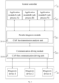
- Fig. 1 is a schematic structural diagram of a diagnosis system for a vehicle central controller according to Embodiment I of the disclosure.
- the diagnosis system for a vehicle central controller includes a central controller 11 and at least one diagnosis device 12.
- Software involved in the disclosure is implemented in the central controller 11.
- the central controller 11 includes a parallel diagnosis module 111 deployed in a main process, and at least one application module 112 deployed in at least one sub-process.
- the at least one diagnosis device 12 is connected to the parallel diagnosis module 111.
- the at least one diagnosis device 12 is configured to send, to the parallel diagnosis module 111, a diagnosis request for diagnosing the application module 112, and the diagnosis request carries a diagnosis identifier.
- the parallel diagnosis module 111 is configured to determine, on the basis of the diagnosis identifier, the application module 112 corresponding to the diagnosis request when the diagnosis request sent by the at least one diagnosis device 12 is received, and transmit, in an IPC manner, the diagnosis request to the application module 112 corresponding to the diagnosis request.
- Each application module 112 is configured to process the received diagnosis request, and transmit a processing result of the diagnosis request to the parallel diagnosis module 111 in an IPC manner.
- the parallel diagnosis module 111 is further configured to send the processing result to the diagnosis device 12 corresponding to the diagnosis request.
- the central controller 11 may be a controller that is integrated by all Electronic Control Unit (ECU) of a vehicle.
- ECU Electronic Control Unit
- a main control chip of the central controller is a System on Chip (SOC).
- SOC System on Chip
- the ECUs integrating the central controller 11 include, but are not limited to, an engine controller unit, an automatic transmission controller unit, a vehicle body controller unit, a vehicle body electronic stability controller unit, a battery management controller unit, and a vehicle controller unit.
- the central controller 11 includes a plurality of ECUs, and each ECU includes at least one application program implementing a corresponding function, such that the central controller 11 includes a plurality of application programs.
- the application module 112 may be an independent diagnosis module of the application program.
- the application module 112 may monitor the application program, and record trouble information (for example, communication loss trouble information) of the application program.
- trouble information for example, communication loss trouble information
- the parallel diagnosis module 111 may be a module that is configured to establish interlinkage between the at least one application module 112 and the at least one diagnosis device 12. Exemplarily, in this embodiment, the parallel diagnosis module 111 is deployed in the main process of the central controller 11, and the application module 112 of the application program is deployed in the at least one sub-process of the central controller 11, such that the parallel diagnosis module 111 and the at least one application module 112 may transmit data in an IPC manner.
- the diagnosis device 12 in this embodiment is connected to the parallel diagnosis module 111.
- the central controller 11 is deployed with a Controller Area Network (CAN) interface and/or an Ethernet communication interface.
- the diagnosis device 12 may be connected to the parallel diagnosis module 111 by means of a CAN bus, or is connected to the parallel diagnosis module 111 by means of Ethernet.
- CAN Controller Area Network
- DoIP Diagnostic communication over Internet Protocol
- UDS-on-CAN Unified Diagnostics Services on CAN
- the central controller 11 further includes a communication driving module; and the at least one diagnosis device 12 is connected to the parallel diagnosis module 111 by means of the communication driving module.
- the communication driving module may be a module that connects the diagnosis device 12 and the parallel diagnosis module 111.
- the communication driving module may belong to a Board Support Package (BSP) portion.
- BSP Board Support Package
- the communication driving module includes a CAN bus communication driving unit; and the at least one diagnosis device 12 is connected to the parallel diagnosis module 111 by means of the CAN bus communication driving unit.
- the communication driving module includes an Ethernet communication driving unit; and the diagnosis device 12 is connected to the parallel diagnosis module 111 by means of the Ethernet communication driving unit.
- the diagnosis device 12 may initiate, to the parallel diagnosis module 111, the diagnosis request for diagnosing the application module 112.
- the plurality of diagnosis devices 12 may be connected to the parallel diagnosis module 111, and the diagnosis requests for different application modules 112 are sent to the parallel diagnosis module 111 at the same time; and the parallel diagnosis module 111 simultaneously establish interlinkage with the plurality of application modules according to the plurality of diagnosis requests.
- the diagnosis device A, the diagnosis device B and the diagnosis device C simultaneously initiate the diagnosis requests for the application module a, the application module b and the application module c to the parallel diagnosis module 111, and in this case, the parallel diagnosis module 111 may respectively establish the interlinkage with the application module a, the application module b and the application module c according to the diagnosis requests.
- the diagnosis request initiated by the diagnosis device 12 may aim at the plurality of application modules. If the diagnosis device 12 initiates the diagnosis request for the plurality of application modules, the parallel diagnosis module 111 may also simultaneously establish the interlinkage with the plurality of application modules according to the diagnosis request.
- the parallel diagnosis module 111 in this embodiment may synchronously establish, according to the received diagnosis request, the interlinkage with the plurality of application modules corresponding to the diagnosis request. That is, the external diagnosis device 12 may establish a diagnosis communication connection with the application module 112 by means of the parallel diagnosis module 111.
- the diagnosis request initiated by the external diagnosis device 12 needs to follow a certain diagnosis communication protocol requirement, for example, the diagnosis request follows a UDS protocol.
- the diagnosis request includes the diagnosis identifier.
- the diagnosis identifier may be identifier information that describes a sending party and a receiving party of the diagnosis request.
- the parallel diagnosis module 111 may determine, according to the diagnosis identifier carried by each diagnosis request, the application module 112 corresponding to each diagnosis request, establish the interlinkage with the application module 112 in an IPC manner, and send each diagnosis request to the application module 112 corresponding to each diagnosis request.
- each application module 112 After receiving the diagnosis request transmitted by the parallel diagnosis module 111 on the basis of IPC, each application module 112 processes the diagnosis request, and transmits a processing result to the parallel diagnosis module 111 in an IPC manner.
- the parallel diagnosis module 111 sends the processing result transmitted by each application module 112 to the diagnosis device 12 corresponding to the diagnosis request, that is, to the diagnosis device 12 of the diagnosis request for the application module 112.
- the application module 112 processes the diagnosis request, may read trouble code information (0x19 service), or may also enter diagnosis session control (0x10 service), clear diagnostic information (0x14 service), reset ECU (0x11 service), control the setting of Diagnostic Trouble Codes (DTC) (0x85 service), read data by means of an Identity (ID) (0x22 service) or write the data by means of the ID (Ox2E service), where ID includes a CAN ID or an Ethernet message ID.
- the parallel diagnosis module 111 in this embodiment has the following functions: 1, performing data interaction with the external diagnosis device 12, for example, receiving the diagnosis request sent by the external diagnosis device 12, and sending the processing result of the diagnosis request to the external diagnosis device 12; 2, extracting the diagnosis identifier of the received diagnosis request; and 3, performing data interaction with the application module 112, for example, searching the corresponding application module 112 according to the diagnosis identifier carried by the received diagnosis request, sending the diagnosis request to the application module 112, and receiving the processing result of the diagnosis request sent by the application module 112.
- the diagnosis device 12 issues the diagnosis request for a plurality of times to the application module 112 within a set time period, when the diagnosis request is issued for the first time, the diagnosis device 12 establishes a communication connection with the application module 112 by means of the parallel diagnosis module 111, such that the application module 112 may establish a session with the diagnosis device 12, and maintain the session when a communication is established for the first time; and when the diagnosis request is not issued for the first time, the application module 112 may record, on the basis of the session, a process of performing data interaction with the diagnosis device 12.
- the diagnosis system for a vehicle central controller includes the central controller and the at least one diagnosis device.
- the central controller includes the parallel diagnosis module deployed in the main process, and the at least one application module deployed in at least one sub-process.
- the parallel diagnosis module in the main process is configured to establish the interlinkage between each application module on the central controller and the external diagnosis device; and the application module in the sub-process is configured to diagnose the application program on the sub-process.
- the parallel diagnosis module is deployed in the main process; and the independent diagnosis module of each application program is deployed in the sub-process.
- the parallel diagnosis module is configured to establish a communication between the at least one application module and the at least one external diagnosis device, so as to realize the real-time and synchronous diagnosis of the plurality of application programs on the central controller, thereby improving the diagnosis efficiency of a controller.
- the diagnosis system for a vehicle central controller provided in this embodiment does not need to change the original design of the diagnosis device. After the plurality of ECUs are deployed in the central controller, the plurality of ECUs may still be independently and synchronously diagnosed according to the original diagnosis device, without depending on the model of a controller chip, such that the diagnosis system has good portability.
- the parallel diagnosis module 111 includes a message processing unit 1112 and a routing management unit 1113.
- the message processing unit 1112 is connected to the at least one diagnosis device 12.
- the message processing unit 1112 is configured to determine the diagnosis identifier of the diagnosis request when the diagnosis request sent by the at least one diagnosis device 12 is received, and send the diagnosis identifier to the routing management unit 1113.
- the routing management unit 1113 is configured to determine, on the basis of the diagnosis identifier, the application module 112 corresponding to the diagnosis request, and transmit, in an IPC manner, the diagnosis request to the application module 112 corresponding to the diagnosis request.
- the parallel diagnosis module 111 consists of the message processing unit 1112 and the routing management unit 1113.
- the message processing unit 1112 is configured to extract the diagnosis identifier of the received diagnosis request.
- the routing management unit 1113 is configured to determine the corresponding application module 112 according to the diagnosis identifier, establish, on the basis of an IPC, communication connection with the application module 112 corresponding to the diagnosis request, and transmit the diagnosis request to the application module 112.
- the application module 112 is further configured to execute at least one of the following operations.
- Security access verification is performed on the received diagnosis request, and a verification result of the diagnosis request is transmitted to the parallel diagnosis module 111 in an IPC manner.
- a DTC of the application program running in each application module 112 is recorded, and a diagnostic trouble state of the application program running in each application module 112 is maintained.
- a session state of the application module 112 and the parallel diagnosis module 111 is recorded.
- the application module 112 may not only perform diagnosis service request processing, but also perform security access verification, session state management, DTC recording, and diagnostic trouble state maintenance. Due to the constantly changing of the trouble state, including the current trouble and a historical trouble, maintaining the diagnostic trouble state can update the trouble state in real time.
- the application module 112 includes a diagnosis processing unit and a diagnosis storage unit.
- the diagnosis processing unit is configured to execute at least one of the following operations: recording a session state of the application module 112 and the parallel diagnosis module 111; performing security access verification on the received diagnosis request, and transmitting the verification result of the diagnosis request to the parallel diagnosis module 111 in an IPC manner; and processing the received diagnosis request, and transmitting the processing result of the diagnosis request to the parallel diagnosis module 111 in an IPC manner.
- the diagnosis storage unit is configured to record the DTC of the application program running in the application module 112, and maintain the diagnostic trouble state of the application program running in the application module 112.
- the diagnosis processing unit is further configured to provide a diagnosis service interface to the application program deployed in the application module.
- the diagnosis storage unit is further configured to provide a diagnosis storage interface to the application program deployed in the application module.
- diagnosis processing unit and the diagnosis storage unit of the at least one application module may be implemented by using the same code, but each application module needs to be integrated with the diagnosis processing unit and the diagnosis storage unit.
- Diagnosis data for example, the DTC
- diagnostic information of each application module 112 may be respectively stored to a data storage space corresponding to each application module.
- the parallel diagnosis module 111 of the main process may acquire the diagnosis data of each application module 112 by means of a mechanism of IPC.
- the application module 112 may also perform session state management, security access verification, DTC recording, and diagnostic trouble state maintenance. Therefore, trouble diagnosis of the plurality of application programs of the central controller is realized.
- Fig. 2 is a schematic structural diagram of a diagnosis system for a vehicle central controller according to Embodiment II of the disclosure.
- the central controller further includes a communication driving module; and the at least one diagnosis device is connected to the parallel diagnosis module by means of the communication driving module.
- the communication driving module includes a CAN bus communication driving unit; and the at least one diagnosis device is connected to the parallel diagnosis module by means of the CAN bus communication driving unit.
- the diagnosis identifier includes a request message identifier.
- the parallel diagnosis module includes a CAN bus transmission analysis unit.
- the CAN bus transmission analysis unit is configured to analyze the diagnosis request, and acquire the request message identifier of the diagnosis request.
- the parallel diagnosis module is configured to call the CAN bus transmission analysis unit to analyze the diagnosis request when the diagnosis request sent by the at least one diagnosis device on the basis of the CAN bus communication driving unit is received, so as to obtain the request message identifier of the diagnosis request, determine, on the basis of the request message identifier, the application module corresponding to the diagnosis request, and transmit, in an IPC manner, the diagnosis request to the application module corresponding to the diagnosis request.
- the diagnosis system for a vehicle central controller includes a central controller 11 and at least one diagnosis device 12.
- the central controller 11 includes a parallel diagnosis module 111 deployed in a main process, at least one application module 112 deployed in at least one sub-process, and a communication driving module 213.
- the communication driving module 213 includes a CAN bus communication driving unit 2131.
- the parallel diagnosis module 111 includes the CAN bus transmission analysis unit 2111.
- the diagnosis device 12 is connected to the parallel diagnosis module 111 by means of the CAN bus communication driving unit 2131.
- the diagnosis device 12 is configured to send, to the parallel diagnosis module 111, a diagnosis request for diagnosing the application module 112; and the diagnosis request carries a diagnosis identifier, and the diagnosis identifier includes the request message identifier.
- the parallel diagnosis module 111 is configured to call the CAN bus transmission analysis unit 2111 to analyze the diagnosis request when the diagnosis request sent by the at least one diagnosis device 12 on the basis of the CAN bus communication driving unit 2131 is received, so as to obtain the request message identifier of the diagnosis request, determine, on the basis of the request message identifier, the application module 112 corresponding to the diagnosis request, and transmit, in an IPC manner, the diagnosis request to the application module 112 corresponding to the diagnosis request.
- Each application module 112 is configured to process the received diagnosis request, and transmit a processing result of the diagnosis request to the parallel diagnosis module 111 in an IPC manner.
- the parallel diagnosis module 111 is further configured to send the processing result to the diagnosis device 12 corresponding to the diagnosis request.
- the request message identifier may be a Controller Area Network Identity Document (CANID).
- CANID Controller Area Network Identity Document
- the parallel diagnosis module 111 in this embodiment may analyze the diagnosis request by calling the CAN bus transmission analysis unit 2111, and acquire the request message identifier of the diagnosis request.
- the diagnosis request sent by the external diagnosis device is received by means of the CAN bus communication driving unit of the communication driving module; the diagnosis request is analyzed by the CAN bus transmission analysis unit of the parallel diagnosis module, a diagnosis message data packet portion of the diagnosis request is acquired, and the request message identifier is extracted from the diagnosis message data packet portion, so as to determine the corresponding application module on the basis of the request message identifier; and interlinkage with the application module is established.
- Fig. 3 is a schematic structural diagram of a diagnosis system for a vehicle central controller according to Embodiment III of the disclosure.
- the central controller further includes a communication driving module; and the diagnosis device is connected to the parallel diagnosis module by means of the communication driving module.
- the communication driving module includes an Ethernet communication driving unit; and the at least one diagnosis device is connected to the parallel diagnosis module by means of the Ethernet communication driving unit.
- the diagnosis identifier includes a diagnosis node identifier.
- the parallel diagnosis module includes an Ethernet transmission analysis unit. The Ethernet transmission analysis unit is configured to analyze a diagnosis request, and acquire the diagnosis node identifier of the diagnosis request.
- the parallel diagnosis module is configured to call the Ethernet transmission analysis unit to analyze the diagnosis request when the diagnosis request sent by the at least one diagnosis device on the basis of the Ethernet communication driving unit is received, so as to obtain the diagnosis node identifier of the diagnosis request, determine, on the basis of the diagnosis node identifier, the application module corresponding to the diagnosis request, and transmit, in an IPC manner, the diagnosis request to the application module corresponding to the diagnosis request.
- the diagnosis system for a vehicle central controller includes a central controller 11 and at least one diagnosis device 12.
- the central controller 11 includes a parallel diagnosis module 111 deployed in a main process, at least one application module 112 deployed in at least one sub-process, and a communication driving module 213.
- the communication driving module 213 includes the Ethernet communication driving unit 3132.
- the parallel diagnosis module includes the Ethernet transmission analysis unit 3112.
- the diagnosis device 12 is connected to the parallel diagnosis module 111 by means of the Ethernet communication driving unit 3132.
- the diagnosis device 12 is configured to send, to the parallel diagnosis module 111, the diagnosis request for diagnosing the application module 112; and the diagnosis request carries a diagnosis identifier, and the diagnosis identifier includes the diagnosis node identifier.
- the parallel diagnosis module 111 is configured to call the Ethernet transmission analysis unit 3112 to analyze the diagnosis request when the diagnosis request sent by the at least one diagnosis device 12 on the basis of the Ethernet communication driving unit 3132 is received, so as to obtain the diagnosis node identifier of the diagnosis request, determine, on the basis of the diagnosis node identifier, the application module 112 corresponding to the diagnosis request, and transmit, in an IPC manner, the diagnosis request to the application module 112 corresponding to the diagnosis request.
- the application module 112 is configured to process the received diagnosis request, and transmit a processing result of the diagnosis request to the parallel diagnosis module 111 in an IPC manner.
- the parallel diagnosis module 111 is further configured to send the processing result to the diagnosis device 12 corresponding to the diagnosis request.
- the diagnosis node identifier may be an Internet Protocol (IP) address or a port number (IP/PORT).
- IP Internet Protocol
- IP/PORT a port number
- the parallel diagnosis module 111 in this embodiment may analyze the diagnosis request by calling the Ethernet transmission analysis unit 3112, and acquire the diagnosis node identifier of the diagnosis request.
- the diagnosis request sent by the external diagnosis device is received by means of the Ethernet communication driving unit of the communication driving module; the diagnosis request is analyzed by the Ethernet transmission analysis unit of the parallel diagnosis module, a diagnosis message data packet portion of the diagnosis request is acquired, and the diagnosis node identifier is extracted from the diagnosis message data packet portion, so as to determine the corresponding application module on the basis of the diagnosis node identifier; and interlinkage with the application module is established.
- the communication driving module provided in this embodiment may further include the Ethernet communication driving unit and a CAN bus communication driving unit; and the parallel diagnosis module also includes the Ethernet transmission analysis unit and a CAN bus transmission analysis unit.
- a diagnosis message determination unit may further be deployed in the communication driving module.
- the diagnosis message determination unit determines whether the diagnosis request is a request of a diagnosis message type. That is, optionally, the communication driving module includes the diagnosis message determination unit.
- the diagnosis message determination unit is configured to determine whether the diagnosis request of the application module that is sent by the at least one diagnosis device is the request of the diagnosis message type, and transmit the diagnosis request to the parallel diagnosis module when the diagnosis request of the application module that is sent by the at least one diagnosis device is the request of the diagnosis message type.
- the diagnosis message type may be a preset message type.
- the diagnosis message type may be set by means of a preset diagnosis identifier.
- diagnosis request is the request of the diagnosis message type may be determined on the basis of the diagnosis identifier of the diagnosis request. For example, if the diagnosis identifier carried by the diagnosis request is 101, 301 or 401, the diagnosis request is the request of the diagnosis message type.
- the communication driving module may call the CAN bus communication driving unit or the Ethernet communication driving unit, acquire the diagnosis identifier of the diagnosis request, and determine, on the basis of the diagnosis message determination unit, whether the diagnosis request is the request of the diagnosis message type. If the diagnosis request is the request of the diagnosis message type, the diagnosis request is transmitted to the parallel diagnosis module by means of the communication driving module, so as to cause the parallel diagnosis module to establish interlinkage with the application module corresponding to the diagnosis request, thereby diagnosing the application module.
- diagnosis request is not the request of the diagnosis message type
- diagnosis request is processed on the basis of a non-diagnosis message processing module in the central controller.
- diagnosis request is the request of a preset diagnosis message type. If the diagnosis request is the request of a preset diagnosis message type, the diagnosis request is transmitted to the parallel diagnosis module. Therefore, the filtration of a diagnosis message is realized, a non-preset diagnosis request is prevented from being processed, and the safety of the diagnosis system for a vehicle central controller is improved.
- Fig. 4A is a schematic flowchart of a diagnosis method for a vehicle central controller according to Embodiment IV of the disclosure.
- This embodiment may be suitable for a situation of diagnosing a plurality of application programs in a central controller, for example, suitable for a situation of diagnosing the plurality of application programs in the central controller at the same time.
- the method is suitable for a diagnosis system for a vehicle central controller.
- the system may be implemented by hardware and/or software. The method includes the following steps.
- a diagnosis request that is sent by at least one diagnosis device and diagnoses an application module is received on the basis of a parallel diagnosis module deployed in a main process of a central controller, and the diagnosis request carries a diagnosis identifier.
- the step of receiving, on the basis of a parallel diagnosis module deployed in a main process of a central controller, a diagnosis request that is sent by at least one diagnosis device and diagnoses an application module includes: receiving, by the parallel diagnosis module deployed in the main process of the central controller by means of a communication driving module of the central controller, the diagnosis request that is sent by the at least one diagnosis device and diagnoses the application module.
- the central controller further includes the communication driving module; and the diagnosis device is connected to the parallel diagnosis module by means of the communication driving module.
- the communication driving module includes a CAN bus communication driving unit.
- the parallel diagnosis module deployed in the main process of the central controller receives, by means of the CAN bus communication driving unit, the diagnosis request that is sent by at least one diagnosis device and diagnoses an application module.
- the diagnosis device is connected to the parallel diagnosis module by means of the CAN bus communication driving unit.
- the communication driving module includes an Ethernet communication driving unit.
- the parallel diagnosis module deployed in the main process of the central controller receives, by means of the Ethernet communication driving unit, the diagnosis request that is sent by at least one diagnosis device and diagnoses an application module.
- the diagnosis device is connected to the parallel diagnosis module by means of the Ethernet communication driving unit.
- the parallel diagnosis module determines the application module corresponding to the diagnosis request on the basis of the diagnosis identifier, and transmits, in an IPC manner, the diagnosis request to the application module corresponding to the diagnosis request.
- the step of determining, by the parallel diagnosis module, the application module corresponding to the diagnosis request on the basis of the diagnosis identifier, and transmitting, in an IPC manner, the diagnosis request to the application module corresponding to the diagnosis request includes: receiving, by a message processing unit of the parallel diagnosis module, the diagnosis request sent by the at least one diagnosis device, determining a diagnosis identifier of the diagnosis request, and sending the diagnosis identifier to a routing management unit of the parallel diagnosis module; and by means of the routing management unit of the parallel diagnosis module, determining, on the basis of the diagnosis identifier, the application module corresponding to the diagnosis request, and transmitting, in an IPC manner, the diagnosis request to the application module corresponding to the diagnosis request.
- the diagnosis identifier includes a request message identifier.
- the parallel diagnosis module includes a CAN bus transmission analysis unit. The step of determining, by the parallel diagnosis module, the application module corresponding to the diagnosis request on the basis of the diagnosis identifier, and transmitting, in an IPC manner, the diagnosis request to the application module corresponding to the diagnosis request includes the following operation.
- the parallel diagnosis module calls the CAN bus transmission analysis unit to analyze the diagnosis request when the diagnosis request sent by the at least one diagnosis device on the basis of the CAN bus communication driving unit is received, so as to obtain the request message identifier of the diagnosis request, determines, on the basis of the request message identifier, the application module corresponding to the diagnosis request, and transmits, in an IPC manner, the diagnosis request to the application module corresponding to the diagnosis request.
- the diagnosis identifier includes a diagnosis node identifier.
- the parallel diagnosis module includes an Ethernet transmission analysis unit. The step of determining, by the parallel diagnosis module, the application module corresponding to the diagnosis request on the basis of the diagnosis identifier, and transmitting, in an IPC manner, the diagnosis request to the application module corresponding to the diagnosis request includes the following operation.
- the parallel diagnosis module calls the Ethernet transmission analysis unit to analyze the diagnosis request when the diagnosis request sent by the at least one diagnosis device on the basis of the Ethernet communication driving unit is received, so as to obtain the diagnosis node identifier of the diagnosis request, determine, on the basis of the diagnosis node identifier, the application module corresponding to the diagnosis request, and transmit, in an IPC manner, the diagnosis request to the application module corresponding to the diagnosis request.
- the parallel diagnosis module acquires a processing result of the diagnosis request from the application module in an IPC manner, and the processing result of the diagnosis request is obtained by processing the received diagnosis request by means of the application module.
- the method further includes at least one of the followings.
- the parallel diagnosis module acquires a verification result of the diagnosis request from the application module in an IPC manner, and the verification result of the diagnosis request is obtained by performing security access verification on the received diagnosis request by the application module.
- a DTC of the application program running in the application module is recorded on the basis of the application module, and a diagnostic trouble state of the application program running in the application module is maintained.
- a session state of the application module and the parallel diagnosis module is recorded on the basis of the application module.
- the parallel diagnosis module sends the processing result to the diagnosis device corresponding to the diagnosis request.
- the parallel diagnosis module may send the processing result to the diagnosis device corresponding to the diagnosis request on the basis of the communication driving module.
- the parallel diagnosis module may send the processing result to the diagnosis device corresponding to the diagnosis request on the basis of the CAN bus communication driving unit of the communication driving module.
- the parallel diagnosis module may send the processing result to the diagnosis device corresponding to the diagnosis request on the basis of the Ethernet communication driving unit of the communication driving module.
- the method further includes: determining whether the diagnosis request of the application module that is sent by the at least one diagnosis device is a request of a diagnosis message type, and transmitting the diagnosis request to the parallel diagnosis module when the diagnosis request of the application module that is sent by the at least one diagnosis device is the request of the diagnosis message type.
- the technical solution of this embodiment by performing data interaction between the parallel diagnosis module established in the main process and the external diagnosis device and the application module in the at least one sub-process, the real-time diagnosis of the plurality of application programs on the central controller at the same time is realized, such that the diagnosis efficiency of the controller is improved.
- the original design of the diagnosis device does not need to be changed.
- the plurality of ECUs may still be independently and synchronously diagnosed according to the original diagnosis device, without depending on the model of a controller chip, such that the diagnosis system has good portability.
- this embodiment further provides another diagnosis method for a vehicle central controller, as shown in Fig. 4B .
- the method includes the following steps.
- the diagnosis request is received, and a message communication ID ETH PORT or CANID is acquired.
- the non-diagnosis message processing module processes the diagnosis request.
- the diagnosis request is analyzed by means of a UDS-On-Can/DoIP transmission layer.
- the ID ETH PORT or CANID of the diagnosis request is extracted, and the application module corresponding to the diagnosis request is matched.
- diagnosis session interlinkage and security access verification are established.
- the diagnosis request is processed (for example, 0X22, 0X2E, 0X31, ect.)
- diagnosis service implementation and data storage are performed.
- the real-time diagnosis of the plurality of application programs on the central controller at the same time is realized, such that the diagnosis efficiency of the controller is improved.
Landscapes
- Engineering & Computer Science (AREA)
- Theoretical Computer Science (AREA)
- Physics & Mathematics (AREA)
- General Physics & Mathematics (AREA)
- General Engineering & Computer Science (AREA)
- Automation & Control Theory (AREA)
- Software Systems (AREA)
- Quality & Reliability (AREA)
- Health & Medical Sciences (AREA)
- Biomedical Technology (AREA)
- Test And Diagnosis Of Digital Computers (AREA)
- Small-Scale Networks (AREA)
Abstract
Description
- The disclosure claims priority to
Chinese Patent Application No. 202110697531.0 filed to the China National Intellectual Property Administration on June 23, 2021 - Embodiments of the disclosure relate to technical field of vehicle central controllers, for example, to a diagnosis system and method for a vehicle central controller.
- At present, with the development of the intelligent connected vehicle industry and technology, the electronic and electrical architecture of the entire vehicle is also changed from a distributed architecture to a centralized architecture. A bus architecture of a distributed architecture controller unit is gradually evolved into an architectural form that combines a central control unit with a regional communication.
- As the electronic and electrical architecture of the entire vehicle develops, a vehicle controller tends to be integrated, the number of the vehicle controllers is also lower than before, and a plurality of application programs with different functions are integrated onto the same hardware controller. In a vehicle controller diagnosis method in the related art, an application program on a controller may be diagnosed, but the plurality of application programs in the controller cannot be diagnosed independently.
- Therefore, the following technical problems exist in the related art. The diagnosis efficiency of a vehicle controller is relatively low; and when there are troubles in the plurality of application programs on the controller at the same time, real-time diagnosis of the plurality of application programs cannot be realized in the related art.
- Embodiments of the disclosure provide a diagnosis system and method for a vehicle central controller, to realize synchronization and real-time diagnosis of a plurality of application programs on a vehicle, so as to improve the diagnosis efficiency of a vehicle controller.
- According to a first aspect, an embodiment of the disclosure provides a diagnosis system for a vehicle central controller. The diagnosis system includes a central controller and at least one diagnosis device. The central controller includes a parallel diagnosis module deployed in a main process, and at least one application module deployed in at least one sub-process.
- The at least one diagnosis device is connected to the parallel diagnosis module; the at least one diagnosis device is configured to send, to the parallel diagnosis module, a diagnosis request for diagnosing the application module; and the diagnosis request carries a diagnosis identifier.
- The parallel diagnosis module is configured to determine, on the basis of the diagnosis identifier, the application module corresponding to the diagnosis request when the diagnosis request sent by the at least one diagnosis device is received, and transmit, in a Inter-Process Communication manner, the diagnosis request to the application module corresponding to the diagnosis request.
- Each application module is configured to process the received diagnosis request, and transmit a processing result of the diagnosis request to the parallel diagnosis module in an IPC manner.
- The parallel diagnosis module is further configured to send the processing result to the diagnosis device corresponding to the diagnosis request.
- According to a second aspect, an embodiment of the disclosure further provides a diagnosis method for a vehicle central controller. The diagnosis method includes the following operations.
- A diagnosis request that is sent by at least one diagnosis device and diagnoses an application module is received on the basis of a parallel diagnosis module deployed in a main process of a central controller, and the diagnosis request carries a diagnosis identifier.
- The parallel diagnosis module determines the application module corresponding to the diagnosis request on the basis of the diagnosis identifier, and transmits, in an IPC manner, the diagnosis request to the application module corresponding to the diagnosis request.
- The parallel diagnosis module acquires a processing result of the diagnosis request from the application module in an IPC manner, and the processing result of the diagnosis request is obtained by processing the received diagnosis request by means of the application module.
- The parallel diagnosis module sends the processing result to the diagnosis device corresponding to the diagnosis request.
-
-
Fig. 1 is a schematic structural diagram of a diagnosis system for a vehicle central controller according to Embodiment I of the disclosure. -
Fig. 2 is a schematic structural diagram of a diagnosis system for a vehicle central controller according to Embodiment II of the disclosure. -
Fig. 3 is a schematic structural diagram of a diagnosis system for a vehicle central controller according to Embodiment III of the disclosure. -
Fig. 4A is a schematic flowchart of a diagnosis method for a vehicle central controller according to Embodiment IV of the disclosure. -
Fig. 4B is a schematic flowchart of another diagnosis method for a vehicle central controller according to Embodiment IV of the disclosure. - The disclosure is described in detail below with reference to the accompanying drawings and embodiments.
-
Fig. 1 is a schematic structural diagram of a diagnosis system for a vehicle central controller according to Embodiment I of the disclosure. As shown inFig. 1 , the diagnosis system for a vehicle central controller includes acentral controller 11 and at least onediagnosis device 12. Software involved in the disclosure is implemented in thecentral controller 11. Thecentral controller 11 includes aparallel diagnosis module 111 deployed in a main process, and at least oneapplication module 112 deployed in at least one sub-process. The at least onediagnosis device 12 is connected to theparallel diagnosis module 111. The at least onediagnosis device 12 is configured to send, to theparallel diagnosis module 111, a diagnosis request for diagnosing theapplication module 112, and the diagnosis request carries a diagnosis identifier. Theparallel diagnosis module 111 is configured to determine, on the basis of the diagnosis identifier, theapplication module 112 corresponding to the diagnosis request when the diagnosis request sent by the at least onediagnosis device 12 is received, and transmit, in an IPC manner, the diagnosis request to theapplication module 112 corresponding to the diagnosis request. Eachapplication module 112 is configured to process the received diagnosis request, and transmit a processing result of the diagnosis request to theparallel diagnosis module 111 in an IPC manner. Theparallel diagnosis module 111 is further configured to send the processing result to thediagnosis device 12 corresponding to the diagnosis request. - In this embodiment, the
central controller 11 may be a controller that is integrated by all Electronic Control Unit (ECU) of a vehicle. Exemplarily, a main control chip of the central controller is a System on Chip (SOC). The ECUs integrating thecentral controller 11 include, but are not limited to, an engine controller unit, an automatic transmission controller unit, a vehicle body controller unit, a vehicle body electronic stability controller unit, a battery management controller unit, and a vehicle controller unit. - The
central controller 11 includes a plurality of ECUs, and each ECU includes at least one application program implementing a corresponding function, such that thecentral controller 11 includes a plurality of application programs. - The
application module 112 may be an independent diagnosis module of the application program. Theapplication module 112 may monitor the application program, and record trouble information (for example, communication loss trouble information) of the application program. For each application program included in thecentral controller 11, theapplication module 112 for performing independent diagnosis on the application program is provided. Theparallel diagnosis module 111 may be a module that is configured to establish interlinkage between the at least oneapplication module 112 and the at least onediagnosis device 12. Exemplarily, in this embodiment, theparallel diagnosis module 111 is deployed in the main process of thecentral controller 11, and theapplication module 112 of the application program is deployed in the at least one sub-process of thecentral controller 11, such that theparallel diagnosis module 111 and the at least oneapplication module 112 may transmit data in an IPC manner. - Exemplarily, the
diagnosis device 12 in this embodiment is connected to theparallel diagnosis module 111. Optionally, thecentral controller 11 is deployed with a Controller Area Network (CAN) interface and/or an Ethernet communication interface. Thediagnosis device 12 may be connected to theparallel diagnosis module 111 by means of a CAN bus, or is connected to theparallel diagnosis module 111 by means of Ethernet. Exemplarily, there is a transmission layer protocol stack of Diagnostic communication over Internet Protocol (DoIP) and Unified Diagnostics Services on CAN (UDS-on-CAN) in theparallel diagnosis module 111, supporting theexternal diagnosis device 12 to perform Unified Diagnostic Services (UDS) on the plurality of ECUs of thecentral controller 11 by means of different buses. - Optionally, the
central controller 11 further includes a communication driving module; and the at least onediagnosis device 12 is connected to theparallel diagnosis module 111 by means of the communication driving module. The communication driving module may be a module that connects thediagnosis device 12 and theparallel diagnosis module 111. In an implementation, the communication driving module may belong to a Board Support Package (BSP) portion. - In an implementation, the communication driving module includes a CAN bus communication driving unit; and the at least one
diagnosis device 12 is connected to theparallel diagnosis module 111 by means of the CAN bus communication driving unit. In another implementation, the communication driving module includes an Ethernet communication driving unit; and thediagnosis device 12 is connected to theparallel diagnosis module 111 by means of the Ethernet communication driving unit. - The
diagnosis device 12 may initiate, to theparallel diagnosis module 111, the diagnosis request for diagnosing theapplication module 112. In an implementation, the plurality ofdiagnosis devices 12 may be connected to theparallel diagnosis module 111, and the diagnosis requests fordifferent application modules 112 are sent to theparallel diagnosis module 111 at the same time; and theparallel diagnosis module 111 simultaneously establish interlinkage with the plurality of application modules according to the plurality of diagnosis requests. - Exemplarily, the diagnosis device A, the diagnosis device B and the diagnosis device C simultaneously initiate the diagnosis requests for the application module a, the application module b and the application module c to the
parallel diagnosis module 111, and in this case, theparallel diagnosis module 111 may respectively establish the interlinkage with the application module a, the application module b and the application module c according to the diagnosis requests. - In another implementation, the diagnosis request initiated by the
diagnosis device 12 may aim at the plurality of application modules. If thediagnosis device 12 initiates the diagnosis request for the plurality of application modules, theparallel diagnosis module 111 may also simultaneously establish the interlinkage with the plurality of application modules according to the diagnosis request. - In other words, the
parallel diagnosis module 111 in this embodiment may synchronously establish, according to the received diagnosis request, the interlinkage with the plurality of application modules corresponding to the diagnosis request. That is, theexternal diagnosis device 12 may establish a diagnosis communication connection with theapplication module 112 by means of theparallel diagnosis module 111. - The diagnosis request initiated by the
external diagnosis device 12 needs to follow a certain diagnosis communication protocol requirement, for example, the diagnosis request follows a UDS protocol. - In this embodiment, the diagnosis request includes the diagnosis identifier. The diagnosis identifier may be identifier information that describes a sending party and a receiving party of the diagnosis request. Exemplarily, after receiving at least one diagnosis request, the
parallel diagnosis module 111 may determine, according to the diagnosis identifier carried by each diagnosis request, theapplication module 112 corresponding to each diagnosis request, establish the interlinkage with theapplication module 112 in an IPC manner, and send each diagnosis request to theapplication module 112 corresponding to each diagnosis request. - After receiving the diagnosis request transmitted by the
parallel diagnosis module 111 on the basis of IPC, eachapplication module 112 processes the diagnosis request, and transmits a processing result to theparallel diagnosis module 111 in an IPC manner. Theparallel diagnosis module 111 sends the processing result transmitted by eachapplication module 112 to thediagnosis device 12 corresponding to the diagnosis request, that is, to thediagnosis device 12 of the diagnosis request for theapplication module 112. - The
application module 112 processes the diagnosis request, may read trouble code information (0x19 service), or may also enter diagnosis session control (0x10 service), clear diagnostic information (0x14 service), reset ECU (0x11 service), control the setting of Diagnostic Trouble Codes (DTC) (0x85 service), read data by means of an Identity (ID) (0x22 service) or write the data by means of the ID (Ox2E service), where ID includes a CAN ID or an Ethernet message ID. - To sum up, the
parallel diagnosis module 111 in this embodiment has the following functions: 1, performing data interaction with theexternal diagnosis device 12, for example, receiving the diagnosis request sent by theexternal diagnosis device 12, and sending the processing result of the diagnosis request to theexternal diagnosis device 12; 2, extracting the diagnosis identifier of the received diagnosis request; and 3, performing data interaction with theapplication module 112, for example, searching thecorresponding application module 112 according to the diagnosis identifier carried by the received diagnosis request, sending the diagnosis request to theapplication module 112, and receiving the processing result of the diagnosis request sent by theapplication module 112. - Definitely, if the
external diagnosis device 12 issues the diagnosis request for a plurality of times to theapplication module 112 within a set time period, when the diagnosis request is issued for the first time, thediagnosis device 12 establishes a communication connection with theapplication module 112 by means of theparallel diagnosis module 111, such that theapplication module 112 may establish a session with thediagnosis device 12, and maintain the session when a communication is established for the first time; and when the diagnosis request is not issued for the first time, theapplication module 112 may record, on the basis of the session, a process of performing data interaction with thediagnosis device 12. - The diagnosis system for a vehicle central controller provided in this embodiment includes the central controller and the at least one diagnosis device. The central controller includes the parallel diagnosis module deployed in the main process, and the at least one application module deployed in at least one sub-process. The parallel diagnosis module in the main process is configured to establish the interlinkage between each application module on the central controller and the external diagnosis device; and the application module in the sub-process is configured to diagnose the application program on the sub-process. In the disclosure, the parallel diagnosis module is deployed in the main process; and the independent diagnosis module of each application program is deployed in the sub-process. The parallel diagnosis module is configured to establish a communication between the at least one application module and the at least one external diagnosis device, so as to realize the real-time and synchronous diagnosis of the plurality of application programs on the central controller, thereby improving the diagnosis efficiency of a controller. In addition, the diagnosis system for a vehicle central controller provided in this embodiment does not need to change the original design of the diagnosis device. After the plurality of ECUs are deployed in the central controller, the plurality of ECUs may still be independently and synchronously diagnosed according to the original diagnosis device, without depending on the model of a controller chip, such that the diagnosis system has good portability.
- In an implementation, optionally, the
parallel diagnosis module 111 includes amessage processing unit 1112 and arouting management unit 1113. Themessage processing unit 1112 is connected to the at least onediagnosis device 12. Themessage processing unit 1112 is configured to determine the diagnosis identifier of the diagnosis request when the diagnosis request sent by the at least onediagnosis device 12 is received, and send the diagnosis identifier to therouting management unit 1113. Therouting management unit 1113 is configured to determine, on the basis of the diagnosis identifier, theapplication module 112 corresponding to the diagnosis request, and transmit, in an IPC manner, the diagnosis request to theapplication module 112 corresponding to the diagnosis request. - In an optional implementation, the
parallel diagnosis module 111 consists of themessage processing unit 1112 and therouting management unit 1113. Themessage processing unit 1112 is configured to extract the diagnosis identifier of the received diagnosis request. Therouting management unit 1113 is configured to determine thecorresponding application module 112 according to the diagnosis identifier, establish, on the basis of an IPC, communication connection with theapplication module 112 corresponding to the diagnosis request, and transmit the diagnosis request to theapplication module 112. - The advantage of arranging the
message processing unit 1112 and therouting management unit 1113 in theparallel diagnosis module 111, so as to respectively extract the diagnosis identifier and determine the application module corresponding to the diagnosis identifier lies in that, the communication connection may be established with the plurality of application modules at the same time when the plurality of diagnosis requests are received, so as to improve the diagnosis efficiency of the plurality of application modules. - Optionally, the
application module 112 is further configured to execute at least one of the following operations. - Security access verification is performed on the received diagnosis request, and a verification result of the diagnosis request is transmitted to the
parallel diagnosis module 111 in an IPC manner. - A DTC of the application program running in each
application module 112 is recorded, and a diagnostic trouble state of the application program running in eachapplication module 112 is maintained. - A session state of the
application module 112 and theparallel diagnosis module 111 is recorded. - In an optional implementation, the
application module 112 may not only perform diagnosis service request processing, but also perform security access verification, session state management, DTC recording, and diagnostic trouble state maintenance. Due to the constantly changing of the trouble state, including the current trouble and a historical trouble, maintaining the diagnostic trouble state can update the trouble state in real time. - In an implementation, the
application module 112 includes a diagnosis processing unit and a diagnosis storage unit. The diagnosis processing unit is configured to execute at least one of the following operations: recording a session state of theapplication module 112 and theparallel diagnosis module 111; performing security access verification on the received diagnosis request, and transmitting the verification result of the diagnosis request to theparallel diagnosis module 111 in an IPC manner; and processing the received diagnosis request, and transmitting the processing result of the diagnosis request to theparallel diagnosis module 111 in an IPC manner. The diagnosis storage unit is configured to record the DTC of the application program running in theapplication module 112, and maintain the diagnostic trouble state of the application program running in theapplication module 112. Optionally, the diagnosis processing unit is further configured to provide a diagnosis service interface to the application program deployed in the application module. The diagnosis storage unit is further configured to provide a diagnosis storage interface to the application program deployed in the application module. - It is to be noted that, in an optional implementation, the diagnosis processing unit and the diagnosis storage unit of the at least one application module may be implemented by using the same code, but each application module needs to be integrated with the diagnosis processing unit and the diagnosis storage unit. Diagnosis data (for example, the DTC) of each
application module 112 in the entirecentral controller 11 may be separately stored. That is to say, diagnostic information of eachapplication module 112 may be respectively stored to a data storage space corresponding to each application module. However, theparallel diagnosis module 111 of the main process may acquire the diagnosis data of eachapplication module 112 by means of a mechanism of IPC. - In an optional implementation, the
application module 112 may also perform session state management, security access verification, DTC recording, and diagnostic trouble state maintenance. Therefore, trouble diagnosis of the plurality of application programs of the central controller is realized. -
Fig. 2 is a schematic structural diagram of a diagnosis system for a vehicle central controller according to Embodiment II of the disclosure. In this embodiment, on the basis of each embodiment, optionally, the central controller further includes a communication driving module; and the at least one diagnosis device is connected to the parallel diagnosis module by means of the communication driving module. Optionally, the communication driving module includes a CAN bus communication driving unit; and the at least one diagnosis device is connected to the parallel diagnosis module by means of the CAN bus communication driving unit. Optionally, the diagnosis identifier includes a request message identifier. The parallel diagnosis module includes a CAN bus transmission analysis unit. The CAN bus transmission analysis unit is configured to analyze the diagnosis request, and acquire the request message identifier of the diagnosis request. The parallel diagnosis module is configured to call the CAN bus transmission analysis unit to analyze the diagnosis request when the diagnosis request sent by the at least one diagnosis device on the basis of the CAN bus communication driving unit is received, so as to obtain the request message identifier of the diagnosis request, determine, on the basis of the request message identifier, the application module corresponding to the diagnosis request, and transmit, in an IPC manner, the diagnosis request to the application module corresponding to the diagnosis request. - Exemplarily, as shown in
Fig. 2 , the diagnosis system for a vehicle central controller provided in this embodiment includes acentral controller 11 and at least onediagnosis device 12. Thecentral controller 11 includes aparallel diagnosis module 111 deployed in a main process, at least oneapplication module 112 deployed in at least one sub-process, and acommunication driving module 213. Thecommunication driving module 213 includes a CAN buscommunication driving unit 2131. Theparallel diagnosis module 111 includes the CAN bustransmission analysis unit 2111. Thediagnosis device 12 is connected to theparallel diagnosis module 111 by means of the CAN buscommunication driving unit 2131. Thediagnosis device 12 is configured to send, to theparallel diagnosis module 111, a diagnosis request for diagnosing theapplication module 112; and the diagnosis request carries a diagnosis identifier, and the diagnosis identifier includes the request message identifier. Theparallel diagnosis module 111 is configured to call the CAN bustransmission analysis unit 2111 to analyze the diagnosis request when the diagnosis request sent by the at least onediagnosis device 12 on the basis of the CAN buscommunication driving unit 2131 is received, so as to obtain the request message identifier of the diagnosis request, determine, on the basis of the request message identifier, theapplication module 112 corresponding to the diagnosis request, and transmit, in an IPC manner, the diagnosis request to theapplication module 112 corresponding to the diagnosis request. Eachapplication module 112 is configured to process the received diagnosis request, and transmit a processing result of the diagnosis request to theparallel diagnosis module 111 in an IPC manner. Theparallel diagnosis module 111 is further configured to send the processing result to thediagnosis device 12 corresponding to the diagnosis request. - The request message identifier may be a Controller Area Network Identity Document (CANID). Exemplarily, if the
diagnosis device 12 sends the diagnosis request by means of the CAN buscommunication driving unit 2131, and the diagnosis identifier of the diagnosis request sent by thediagnosis device 12 is the CANID. - Exemplarily, the
parallel diagnosis module 111 in this embodiment may analyze the diagnosis request by calling the CAN bustransmission analysis unit 2111, and acquire the request message identifier of the diagnosis request. - According to the technical solution of this embodiment, the diagnosis request sent by the external diagnosis device is received by means of the CAN bus communication driving unit of the communication driving module; the diagnosis request is analyzed by the CAN bus transmission analysis unit of the parallel diagnosis module, a diagnosis message data packet portion of the diagnosis request is acquired, and the request message identifier is extracted from the diagnosis message data packet portion, so as to determine the corresponding application module on the basis of the request message identifier; and interlinkage with the application module is established. In this way, the real-time diagnosis of the plurality of application programs on the central controller at the same time is realized, a communication mechanism of a diagnosis device in the related art does not need to be changed, and a plurality of ECUs may still be independently and synchronously diagnosed according to the diagnosis device in the related art, such that the applicability of the diagnosis system for a vehicle central controller is improved.
-
Fig. 3 is a schematic structural diagram of a diagnosis system for a vehicle central controller according to Embodiment III of the disclosure. In this embodiment, on the basis of each embodiment, optionally, the central controller further includes a communication driving module; and the diagnosis device is connected to the parallel diagnosis module by means of the communication driving module. Optionally, the communication driving module includes an Ethernet communication driving unit; and the at least one diagnosis device is connected to the parallel diagnosis module by means of the Ethernet communication driving unit. Optionally, the diagnosis identifier includes a diagnosis node identifier. The parallel diagnosis module includes an Ethernet transmission analysis unit. The Ethernet transmission analysis unit is configured to analyze a diagnosis request, and acquire the diagnosis node identifier of the diagnosis request. The parallel diagnosis module is configured to call the Ethernet transmission analysis unit to analyze the diagnosis request when the diagnosis request sent by the at least one diagnosis device on the basis of the Ethernet communication driving unit is received, so as to obtain the diagnosis node identifier of the diagnosis request, determine, on the basis of the diagnosis node identifier, the application module corresponding to the diagnosis request, and transmit, in an IPC manner, the diagnosis request to the application module corresponding to the diagnosis request. - Exemplarily, as shown in
Fig. 3 , the diagnosis system for a vehicle central controller provided in this embodiment includes acentral controller 11 and at least onediagnosis device 12. Thecentral controller 11 includes aparallel diagnosis module 111 deployed in a main process, at least oneapplication module 112 deployed in at least one sub-process, and acommunication driving module 213. Thecommunication driving module 213 includes the Ethernetcommunication driving unit 3132. The parallel diagnosis module includes the Ethernettransmission analysis unit 3112. Thediagnosis device 12 is connected to theparallel diagnosis module 111 by means of the Ethernetcommunication driving unit 3132. Thediagnosis device 12 is configured to send, to theparallel diagnosis module 111, the diagnosis request for diagnosing theapplication module 112; and the diagnosis request carries a diagnosis identifier, and the diagnosis identifier includes the diagnosis node identifier. Theparallel diagnosis module 111 is configured to call the Ethernettransmission analysis unit 3112 to analyze the diagnosis request when the diagnosis request sent by the at least onediagnosis device 12 on the basis of the Ethernetcommunication driving unit 3132 is received, so as to obtain the diagnosis node identifier of the diagnosis request, determine, on the basis of the diagnosis node identifier, theapplication module 112 corresponding to the diagnosis request, and transmit, in an IPC manner, the diagnosis request to theapplication module 112 corresponding to the diagnosis request. Theapplication module 112 is configured to process the received diagnosis request, and transmit a processing result of the diagnosis request to theparallel diagnosis module 111 in an IPC manner. Theparallel diagnosis module 111 is further configured to send the processing result to thediagnosis device 12 corresponding to the diagnosis request. - The diagnosis node identifier may be an Internet Protocol (IP) address or a port number (IP/PORT). Exemplarily, if the
diagnosis device 12 sends the diagnosis request by means of the Ethernet communication driving unit, and the diagnosis identifier of the diagnosis request sent by thediagnosis device 12 is the diagnosis node identifier. - Exemplarily, the
parallel diagnosis module 111 in this embodiment may analyze the diagnosis request by calling the Ethernettransmission analysis unit 3112, and acquire the diagnosis node identifier of the diagnosis request. - According to the technical solution of this embodiment, the diagnosis request sent by the external diagnosis device is received by means of the Ethernet communication driving unit of the communication driving module; the diagnosis request is analyzed by the Ethernet transmission analysis unit of the parallel diagnosis module, a diagnosis message data packet portion of the diagnosis request is acquired, and the diagnosis node identifier is extracted from the diagnosis message data packet portion, so as to determine the corresponding application module on the basis of the diagnosis node identifier; and interlinkage with the application module is established. In this way, the real-time diagnosis of the plurality of application programs on the central controller at the same time is realized, a communication mechanism of a diagnosis device in the related art does not need to be changed, and a plurality of ECUs may still be independently and synchronously diagnosed according to the diagnosis device in the related art, such that the applicability of the diagnosis system for a vehicle central controller is improved.
- Definitely, the communication driving module provided in this embodiment may further include the Ethernet communication driving unit and a CAN bus communication driving unit; and the parallel diagnosis module also includes the Ethernet transmission analysis unit and a CAN bus transmission analysis unit.
- In an implementation, a diagnosis message determination unit may further be deployed in the communication driving module. On the basis of the diagnosis message determination unit, before the parallel diagnosis module acquires the diagnosis identifier of the diagnosis request, the diagnosis message determination unit determines whether the diagnosis request is a request of a diagnosis message type. That is, optionally, the communication driving module includes the diagnosis message determination unit. The diagnosis message determination unit is configured to determine whether the diagnosis request of the application module that is sent by the at least one diagnosis device is the request of the diagnosis message type, and transmit the diagnosis request to the parallel diagnosis module when the diagnosis request of the application module that is sent by the at least one diagnosis device is the request of the diagnosis message type.
- The diagnosis message type may be a preset message type. In an implementation, the diagnosis message type may be set by means of a preset diagnosis identifier.
- Exemplarily, whether the diagnosis request is the request of the diagnosis message type may be determined on the basis of the diagnosis identifier of the diagnosis request. For example, if the diagnosis identifier carried by the diagnosis request is 101, 301 or 401, the diagnosis request is the request of the diagnosis message type.
- Exemplarily, the communication driving module may call the CAN bus communication driving unit or the Ethernet communication driving unit, acquire the diagnosis identifier of the diagnosis request, and determine, on the basis of the diagnosis message determination unit, whether the diagnosis request is the request of the diagnosis message type. If the diagnosis request is the request of the diagnosis message type, the diagnosis request is transmitted to the parallel diagnosis module by means of the communication driving module, so as to cause the parallel diagnosis module to establish interlinkage with the application module corresponding to the diagnosis request, thereby diagnosing the application module.
- Optionally, if the diagnosis request is not the request of the diagnosis message type, the diagnosis request is processed on the basis of a non-diagnosis message processing module in the central controller.
- In an optional implementation, whether the diagnosis request is the request of a preset diagnosis message type is determined by means of the diagnosis message determination unit of the communication driving module; and when the diagnosis request is the request of the preset diagnosis message type, the diagnosis request is transmitted to the parallel diagnosis module. Therefore, the filtration of a diagnosis message is realized, a non-preset diagnosis request is prevented from being processed, and the safety of the diagnosis system for a vehicle central controller is improved.
- It is to be noted that, units and modules included in the system are only divided according to the functional logic, but are not limited to the above divisions, as long as the corresponding functions can be realized. In addition, the specific names of the functional units are only for the convenience of distinguishing from each other, and are not used to limit the scope of protection of the embodiments of the disclosure.
-
Fig. 4A is a schematic flowchart of a diagnosis method for a vehicle central controller according to Embodiment IV of the disclosure. This embodiment may be suitable for a situation of diagnosing a plurality of application programs in a central controller, for example, suitable for a situation of diagnosing the plurality of application programs in the central controller at the same time. The method is suitable for a diagnosis system for a vehicle central controller. The system may be implemented by hardware and/or software. The method includes the following steps. - At S410, a diagnosis request that is sent by at least one diagnosis device and diagnoses an application module is received on the basis of a parallel diagnosis module deployed in a main process of a central controller, and the diagnosis request carries a diagnosis identifier.
- Optionally, the step of receiving, on the basis of a parallel diagnosis module deployed in a main process of a central controller, a diagnosis request that is sent by at least one diagnosis device and diagnoses an application module includes: receiving, by the parallel diagnosis module deployed in the main process of the central controller by means of a communication driving module of the central controller, the diagnosis request that is sent by the at least one diagnosis device and diagnoses the application module. Exemplarily, the central controller further includes the communication driving module; and the diagnosis device is connected to the parallel diagnosis module by means of the communication driving module.
- Optionally, the communication driving module includes a CAN bus communication driving unit. Correspondingly, the parallel diagnosis module deployed in the main process of the central controller receives, by means of the CAN bus communication driving unit, the diagnosis request that is sent by at least one diagnosis device and diagnoses an application module. Exemplarily, the diagnosis device is connected to the parallel diagnosis module by means of the CAN bus communication driving unit.
- Optionally, the communication driving module includes an Ethernet communication driving unit. Correspondingly, the parallel diagnosis module deployed in the main process of the central controller receives, by means of the Ethernet communication driving unit, the diagnosis request that is sent by at least one diagnosis device and diagnoses an application module. Exemplarily, the diagnosis device is connected to the parallel diagnosis module by means of the Ethernet communication driving unit.
- At S420, the parallel diagnosis module determines the application module corresponding to the diagnosis request on the basis of the diagnosis identifier, and transmits, in an IPC manner, the diagnosis request to the application module corresponding to the diagnosis request.
- Optionally, the step of determining, by the parallel diagnosis module, the application module corresponding to the diagnosis request on the basis of the diagnosis identifier, and transmitting, in an IPC manner, the diagnosis request to the application module corresponding to the diagnosis request includes: receiving, by a message processing unit of the parallel diagnosis module, the diagnosis request sent by the at least one diagnosis device, determining a diagnosis identifier of the diagnosis request, and sending the diagnosis identifier to a routing management unit of the parallel diagnosis module; and by means of the routing management unit of the parallel diagnosis module, determining, on the basis of the diagnosis identifier, the application module corresponding to the diagnosis request, and transmitting, in an IPC manner, the diagnosis request to the application module corresponding to the diagnosis request.
- Optionally, the diagnosis identifier includes a request message identifier. The parallel diagnosis module includes a CAN bus transmission analysis unit. The step of determining, by the parallel diagnosis module, the application module corresponding to the diagnosis request on the basis of the diagnosis identifier, and transmitting, in an IPC manner, the diagnosis request to the application module corresponding to the diagnosis request includes the following operation.
- The parallel diagnosis module calls the CAN bus transmission analysis unit to analyze the diagnosis request when the diagnosis request sent by the at least one diagnosis device on the basis of the CAN bus communication driving unit is received, so as to obtain the request message identifier of the diagnosis request, determines, on the basis of the request message identifier, the application module corresponding to the diagnosis request, and transmits, in an IPC manner, the diagnosis request to the application module corresponding to the diagnosis request.
- Optionally, the diagnosis identifier includes a diagnosis node identifier. The parallel diagnosis module includes an Ethernet transmission analysis unit. The step of determining, by the parallel diagnosis module, the application module corresponding to the diagnosis request on the basis of the diagnosis identifier, and transmitting, in an IPC manner, the diagnosis request to the application module corresponding to the diagnosis request includes the following operation.
- The parallel diagnosis module calls the Ethernet transmission analysis unit to analyze the diagnosis request when the diagnosis request sent by the at least one diagnosis device on the basis of the Ethernet communication driving unit is received, so as to obtain the diagnosis node identifier of the diagnosis request, determine, on the basis of the diagnosis node identifier, the application module corresponding to the diagnosis request, and transmit, in an IPC manner, the diagnosis request to the application module corresponding to the diagnosis request.
- At S430, the parallel diagnosis module acquires a processing result of the diagnosis request from the application module in an IPC manner, and the processing result of the diagnosis request is obtained by processing the received diagnosis request by means of the application module.
- Optionally, the method further includes at least one of the followings.
- The parallel diagnosis module acquires a verification result of the diagnosis request from the application module in an IPC manner, and the verification result of the diagnosis request is obtained by performing security access verification on the received diagnosis request by the application module.
- A DTC of the application program running in the application module is recorded on the basis of the application module, and a diagnostic trouble state of the application program running in the application module is maintained.
- A session state of the application module and the parallel diagnosis module is recorded on the basis of the application module.
- At S440, the parallel diagnosis module sends the processing result to the diagnosis device corresponding to the diagnosis request.
- Optionally, the parallel diagnosis module may send the processing result to the diagnosis device corresponding to the diagnosis request on the basis of the communication driving module. Optionally, the parallel diagnosis module may send the processing result to the diagnosis device corresponding to the diagnosis request on the basis of the CAN bus communication driving unit of the communication driving module. Optionally, the parallel diagnosis module may send the processing result to the diagnosis device corresponding to the diagnosis request on the basis of the Ethernet communication driving unit of the communication driving module.
- Optionally, the method further includes: determining whether the diagnosis request of the application module that is sent by the at least one diagnosis device is a request of a diagnosis message type, and transmitting the diagnosis request to the parallel diagnosis module when the diagnosis request of the application module that is sent by the at least one diagnosis device is the request of the diagnosis message type.
- According to the technical solution of this embodiment, by performing data interaction between the parallel diagnosis module established in the main process and the external diagnosis device and the application module in the at least one sub-process, the real-time diagnosis of the plurality of application programs on the central controller at the same time is realized, such that the diagnosis efficiency of the controller is improved. In addition, the original design of the diagnosis device does not need to be changed. After the plurality of ECUs are deployed in the central controller, the plurality of ECUs may still be independently and synchronously diagnosed according to the original diagnosis device, without depending on the model of a controller chip, such that the diagnosis system has good portability.
- It is to be noted that, this embodiment further provides another diagnosis method for a vehicle central controller, as shown in
Fig. 4B . Referring toFig. 4B , the method includes the following steps. - At S1, the main process is started.
- At S2, the diagnosis request is received, and a message communication ID ETH PORT or CANID is acquired.
- At S3, whether the diagnosis request is the request of the diagnosis message type is determined; when the diagnosis request is not the request of the diagnosis message type, S4 is executed; and when the diagnosis request is the request of the diagnosis message type, S5 is executed.
- At S4, the non-diagnosis message processing module processes the diagnosis request.
- At S5, the diagnosis request is analyzed by means of a UDS-On-Can/DoIP transmission layer.
- At S6, the ID ETH PORT or CANID of the diagnosis request is extracted, and the application module corresponding to the diagnosis request is matched.
- At S7, whether to establish interlinkage with the application module is determined; if so, S10 is executed; and if no, S8 is executed.
- At S8, an IPC communication connection is established with the sub-process of the application module.
- At S9, diagnosis session interlinkage and security access verification are established.
- At S10, the diagnosis request is processed (for example, 0X22, 0X2E, 0X31, ect.)
- At S11, diagnosis service implementation and data storage are performed.
- In this implementation, by performing data interaction between the main process and the external diagnosis device and the application module in the at least one sub-process, the real-time diagnosis of the plurality of application programs on the central controller at the same time is realized, such that the diagnosis efficiency of the controller is improved.
Claims (10)
- A diagnosis system for a vehicle central controller, comprising a central controller (11) and at least one diagnosis device (12), wherein the central controller (11) comprises a parallel diagnosis module (111) deployed in a main process, and at least one application module (112) deployed in at least one sub-process;the at least one diagnosis device (12) is connected to the parallel diagnosis module (111); the at least one diagnosis device (12) is configured to send, to the parallel diagnosis module (111), a diagnosis request for diagnosing the application module (112), and the diagnosis request carries a diagnosis identifier;the parallel diagnosis module (111) is configured to determine, on the basis of the diagnosis identifier, the application module (112) corresponding to the diagnosis request when the diagnosis request sent by the at least one diagnosis device (12) is received, and transmit, in a Inter-Process Communication (IPC) manner, the diagnosis request to the application module (112) corresponding to the diagnosis request;each application module (112) is configured to process the received diagnosis request, and transmit a processing result of the diagnosis request to the parallel diagnosis module (111) in an IPC manner; andthe parallel diagnosis module (111) is further configured to send the processing result to the diagnosis device (12) corresponding to the diagnosis request.
- The system according to claim 1, wherein the parallel diagnosis module (111) comprises a message processing unit (1112) and a routing management unit (1113);the message processing unit (1112) is connected to the at least one diagnosis device (12); the message processing unit (1112) is configured to determine the diagnosis identifier of the diagnosis request when the diagnosis request sent by the at least one diagnosis device is received, and send the diagnosis identifier to the routing management unit (1113); andthe routing management unit (1113) is configured to determine, on the basis of the diagnosis identifier, the application module (112) corresponding to the diagnosis request, and transmit, in an IPC manner, the diagnosis request to the application module (112) corresponding to the diagnosis request.
- The system according to claim 1, wherein the central controller (11) further comprises a communication driving module (213); and the at least one diagnosis device (12) is connected to the parallel diagnosis module (111) by means of the communication driving module (213).
- The system according to claim 3, wherein the communication driving module (213) comprises a Controller Area Network (CAN) bus communication driving unit (2131); and the at least one diagnosis device (12) is connected to the parallel diagnosis module (111) by means of the CAN bus communication driving unit (2131).
- The system according to claim 4, wherein the diagnosis identifier comprises a request message identifier; the parallel diagnosis module (111) comprises a CAN bus transmission analysis unit (2111);the CAN bus transmission analysis unit (2111) is configured to analyze the diagnosis request, and acquire the request message identifier of the diagnosis request; andthe parallel diagnosis module (111) is configured to call the CAN bus transmission analysis unit (2111) to analyze the diagnosis request when the diagnosis request sent by the at least one diagnosis device (12) on the basis of the CAN bus communication driving unit (2131) is received, so as to obtain the request message identifier of the diagnosis request, determine, on the basis of the request message identifier, the application module (112) corresponding to the diagnosis request, and transmit, in an IPC manner, the diagnosis request to the application module (112) corresponding to the diagnosis request.
- The system according to claim 3, wherein the communication driving module (213) comprises an Ethernet communication driving unit (3132); and the at least one diagnosis device (12) is connected to the parallel diagnosis module (111) by means of the Ethernet communication driving unit (3132).
- The system according to claim 6, wherein the diagnosis identifier comprises a diagnosis node identifier; the parallel diagnosis module (111) comprises an Ethernet transmission analysis unit (3112);the Ethernet transmission analysis unit (3112) is configured to analyze the diagnosis request, and acquire the diagnosis node identifier of the diagnosis request; andthe parallel diagnosis module (111) is configured to call the Ethernet transmission analysis unit (3112) to analyze the diagnosis request when the diagnosis request sent by the at least one diagnosis device (12) on the basis of the Ethernet communication driving unit (3132) is received, so as to obtain the diagnosis node identifier of the diagnosis request, determine, on the basis of the diagnosis node identifier, the application module (112) corresponding to the diagnosis request, and transmit, in an IPC manner, the diagnosis request to the application module (112) corresponding to the diagnosis request.
- The system according to claim 1, wherein each application module (112) is further configured to execute at least one of the following operations:performing security access verification on the received diagnosis request, and transmitting a verification result of the diagnosis request to the parallel diagnosis module (111) in an IPC manner;recording a Diagnostic Trouble Code (DTC) of the application program running in each application module (112), and maintaining a diagnostic trouble state of the application program running in each application module (112); andrecording a session state of each application module (112) and the parallel diagnosis module (12).
- The system according to claim 3, wherein the communication driving module (213) comprises a diagnosis message determination unit; and
the diagnosis message determination unit is configured to determine whether the diagnosis request of the application module (112) that is sent by the at least one diagnosis device (12) is a request of a diagnosis message type, and transmit the diagnosis request to the parallel diagnosis module (111) when the diagnosis request of the application module (112) that is sent by the at least one diagnosis device (12) is the request of the diagnosis message type. - A diagnosis method for a vehicle central controller, comprising:receiving, on the basis of a parallel diagnosis module (111) deployed in a main process of a central controller (11), a diagnosis request that is sent by at least one diagnosis device (12) and diagnoses an application module (112), wherein the diagnosis request carries a diagnosis identifier;determining, by the parallel diagnosis module (111), the application module (112) corresponding to the diagnosis request on the basis of the diagnosis identifier, and transmitting, in an Inter-Process Communication (IPC) manner, the diagnosis request to the application module (112) corresponding to the diagnosis request;acquiring a processing result of the diagnosis request by the parallel diagnosis module (111) from the application module (112) in an IPC manner, wherein the processing result of the diagnosis request is obtained by processing the received diagnosis request by means of the application module (112); andsending, by the parallel diagnosis module (111), the processing result to the diagnosis device (12) corresponding to the diagnosis request.
Applications Claiming Priority (2)
| Application Number | Priority Date | Filing Date | Title |
|---|---|---|---|
| CN202110697531.0A CN113341933B (en) | 2021-06-23 | 2021-06-23 | Diagnostic system and method for vehicle central controller |
| PCT/CN2022/100294 WO2022268100A1 (en) | 2021-06-23 | 2022-06-22 | Diagnosis system and method for vehicle central controller |
Publications (2)
| Publication Number | Publication Date |
|---|---|
| EP4339725A1 true EP4339725A1 (en) | 2024-03-20 |
| EP4339725A4 EP4339725A4 (en) | 2024-11-13 |
Family
ID=77478083
Family Applications (1)
| Application Number | Title | Priority Date | Filing Date |
|---|---|---|---|
| EP22827593.9A Pending EP4339725A4 (en) | 2021-06-23 | 2022-06-22 | DIAGNOSTIC SYSTEM AND METHOD FOR VEHICLE CENTRAL CONTROLLER |
Country Status (3)
| Country | Link |
|---|---|
| EP (1) | EP4339725A4 (en) |
| CN (1) | CN113341933B (en) |
| WO (1) | WO2022268100A1 (en) |
Cited By (1)
| Publication number | Priority date | Publication date | Assignee | Title |
|---|---|---|---|---|
| CN118609234A (en) * | 2024-05-16 | 2024-09-06 | 中国第一汽车股份有限公司 | Vehicle diagnostic method, device, equipment, storage medium and program product |
Families Citing this family (6)
| Publication number | Priority date | Publication date | Assignee | Title |
|---|---|---|---|---|
| CN113341933B (en) * | 2021-06-23 | 2022-08-19 | 中国第一汽车股份有限公司 | Diagnostic system and method for vehicle central controller |
| CN113960991B (en) * | 2021-11-30 | 2024-08-23 | 北京超星未来科技有限公司 | Vehicle fault diagnosis system, method and device, system-on-chip and vehicle |
| CN114756433A (en) * | 2022-04-29 | 2022-07-15 | 中国第一汽车股份有限公司 | Data processing method, device, equipment and storage medium |
| CN115390548B (en) * | 2022-08-30 | 2025-08-29 | 中控技术股份有限公司 | Control loop identification method, device, storage medium and electronic equipment |
| CN116880456A (en) * | 2023-08-15 | 2023-10-13 | 中国第一汽车股份有限公司 | Vehicle diagnosis method, device, electronic equipment and storage medium |
| CN118760119A (en) * | 2024-06-25 | 2024-10-11 | 中国第一汽车股份有限公司 | Diagnostic method, device, vehicle and storage medium for vehicle-mounted controller |
Family Cites Families (21)
| Publication number | Priority date | Publication date | Assignee | Title |
|---|---|---|---|---|
| KR100461694B1 (en) * | 2001-02-02 | 2004-12-14 | 유지명 | Parallel Tasking System for Communication with Vehicle |
| JP4491439B2 (en) * | 2006-06-30 | 2010-06-30 | 株式会社日立製作所 | Control apparatus and control method |
| CN101807068B (en) * | 2010-02-12 | 2014-12-24 | 深圳市元征软件开发有限公司 | Universal bus parallelism-based vehicle diagnosis system and method |
| CN201707600U (en) * | 2010-02-12 | 2011-01-12 | 深圳市元征软件开发有限公司 | Automobile diagnostic device |
| CN201740649U (en) * | 2010-04-13 | 2011-02-09 | 深圳市元征软件开发有限公司 | Combined automotive diagnosis device |
| DE102011004205A1 (en) * | 2011-02-16 | 2012-08-16 | Robert Bosch Gmbh | System and method for identifying, diagnosing, maintaining and repairing a vehicle |
| CN102270158A (en) * | 2011-08-10 | 2011-12-07 | 深圳市万兴软件有限公司 | Application program multiprocess running method and device |
| JP2013196410A (en) * | 2012-03-21 | 2013-09-30 | Mitsubishi Denki Information Technology Corp | Server device and failure management method and failure management program |
| CN103616886B (en) * | 2013-11-22 | 2016-05-04 | 深圳市道通科技股份有限公司 | One realizes the parallel vehicle diagnosis method of multi-path and automotive diagnostic installation |
| CN104483960B (en) * | 2014-11-10 | 2017-04-19 | 深圳市元征科技股份有限公司 | Automobile diagnosis communication module data transceiving parallel processing method |
| CN107707418B (en) * | 2016-08-09 | 2021-06-15 | 上汽通用汽车有限公司 | Communication diagnosis system and communication diagnosis refreshing method |
| JP6717184B2 (en) * | 2016-12-15 | 2020-07-01 | 株式会社デンソー | In-vehicle control device |
| CN108459966B (en) * | 2018-03-21 | 2021-11-16 | 东软集团股份有限公司 | Method, device and equipment for scheduling test components and computer readable storage medium |
| JP7003975B2 (en) * | 2018-08-10 | 2022-01-21 | 株式会社デンソー | Vehicle information communication system, center device and message transmission method of center device |
| GB2595430B (en) * | 2019-09-02 | 2024-04-17 | Jaguar Land Rover Ltd | Electrical architecture for service-oriented vehicle diagnostics |
| CN110532001A (en) * | 2019-09-09 | 2019-12-03 | 阳光电源股份有限公司 | Flashing method, system, diagnostic equipment and vehicle controller for vehicle controller |
| CN111521408A (en) * | 2020-04-30 | 2020-08-11 | 深圳市元征科技股份有限公司 | Diagnosis request processing method, device, system, equipment and readable storage medium |
| CN112181463A (en) * | 2020-09-29 | 2021-01-05 | 广州汽车集团股份有限公司 | An ECU update method and master node device |
| CN112904828B (en) * | 2021-01-19 | 2022-08-02 | 英博超算(南京)科技有限公司 | Diagnostic system of heterogeneous architecture domain controller |
| CN112817533A (en) * | 2021-01-29 | 2021-05-18 | 深圳忆联信息系统有限公司 | SSD management method, device computer equipment and storage medium |
| CN113341933B (en) * | 2021-06-23 | 2022-08-19 | 中国第一汽车股份有限公司 | Diagnostic system and method for vehicle central controller |
-
2021
- 2021-06-23 CN CN202110697531.0A patent/CN113341933B/en active Active
-
2022
- 2022-06-22 EP EP22827593.9A patent/EP4339725A4/en active Pending
- 2022-06-22 WO PCT/CN2022/100294 patent/WO2022268100A1/en not_active Ceased
Cited By (1)
| Publication number | Priority date | Publication date | Assignee | Title |
|---|---|---|---|---|
| CN118609234A (en) * | 2024-05-16 | 2024-09-06 | 中国第一汽车股份有限公司 | Vehicle diagnostic method, device, equipment, storage medium and program product |
Also Published As
| Publication number | Publication date |
|---|---|
| CN113341933B (en) | 2022-08-19 |
| WO2022268100A1 (en) | 2022-12-29 |
| EP4339725A4 (en) | 2024-11-13 |
| CN113341933A (en) | 2021-09-03 |
Similar Documents
| Publication | Publication Date | Title |
|---|---|---|
| CN113341933B (en) | Diagnostic system and method for vehicle central controller | |
| KR100946991B1 (en) | Vehicle gateway, vehicle network interface device and method | |
| CN105388893B (en) | A kind of CAN communication data monitoring method and system based on OBD interfaces | |
| US12010000B2 (en) | Message sampling method, decapsulation method, node, system and storage medium | |
| CN101442513B (en) | Method for realizing multiple service processing functions and multi-core processor equipment | |
| CN109960634B (en) | Application program monitoring method, device and system | |
| CN111324363A (en) | Equipment upgrading method, upgrading terminal, equipment and storage medium | |
| CN114944969A (en) | Vehicle data processing method, internet of vehicles terminal and computer readable storage medium | |
| CN115291594B (en) | Remote diagnosis system and method for vehicle-mounted domain controller | |
| CN108174400B (en) | Data processing method, system and equipment of terminal equipment | |
| CN121770927A (en) | Double CAN channel fusion J1939 protocol stack of vehicle-mounted terminal and parallel communication diagnosis method | |
| CN114500178A (en) | Intelligent internet of things gateway capable of self-operation and self-maintenance | |
| CN115865651B (en) | Data acquisition method and device, electronic equipment and storage medium | |
| CN113765904B (en) | Authentication method and device | |
| CN215494685U (en) | Industrial data remote debugging acquisition platform | |
| CN219351917U (en) | Vehicle-mounted gateway for judging network state and vehicle | |
| CN114500585A (en) | Epoll-based network sensor acquisition system and method | |
| CN114884765A (en) | PLC bus communication method and system based on relay equipment and relay equipment | |
| CN113220448A (en) | Dual-computer system and control method thereof | |
| CN117215958B (en) | Vehicle-mounted application separation design software and test method thereof | |
| CN116011213B (en) | Data simulation system | |
| CN218463662U (en) | Train signal control system | |
| CN116095063A (en) | Online electronic reading and interaction method and system based on cloud platform | |
| CN121664735A (en) | A vehicle diagnostic communication system | |
| CN121982797A (en) | Method and device for realizing multi-vehicle diagnosis through soft AP local area network |
Legal Events
| Date | Code | Title | Description |
|---|---|---|---|
| STAA | Information on the status of an ep patent application or granted ep patent |
Free format text: STATUS: THE INTERNATIONAL PUBLICATION HAS BEEN MADE |
|
| PUAI | Public reference made under article 153(3) epc to a published international application that has entered the european phase |
Free format text: ORIGINAL CODE: 0009012 |
|
| STAA | Information on the status of an ep patent application or granted ep patent |
Free format text: STATUS: REQUEST FOR EXAMINATION WAS MADE |
|
| 17P | Request for examination filed |
Effective date: 20231211 |
|
| AK | Designated contracting states |
Kind code of ref document: A1 Designated state(s): AL AT BE BG CH CY CZ DE DK EE ES FI FR GB GR HR HU IE IS IT LI LT LU LV MC MK MT NL NO PL PT RO RS SE SI SK SM TR |
|
| DAV | Request for validation of the european patent (deleted) | ||
| DAX | Request for extension of the european patent (deleted) | ||
| A4 | Supplementary search report drawn up and despatched |
Effective date: 20241010 |
|
| RIC1 | Information provided on ipc code assigned before grant |
Ipc: G06F 9/54 20060101ALI20241004BHEP Ipc: G06F 11/30 20060101ALI20241004BHEP Ipc: H04L 12/40 20060101ALI20241004BHEP Ipc: G07C 5/08 20060101ALI20241004BHEP Ipc: G06F 11/07 20060101ALI20241004BHEP Ipc: G05B 23/02 20060101AFI20241004BHEP |
|
| GRAP | Despatch of communication of intention to grant a patent |
Free format text: ORIGINAL CODE: EPIDOSNIGR1 |
|
| STAA | Information on the status of an ep patent application or granted ep patent |
Free format text: STATUS: GRANT OF PATENT IS INTENDED |
|
| INTG | Intention to grant announced |
Effective date: 20260527 |
|
| GRAS | Grant fee paid |
Free format text: ORIGINAL CODE: EPIDOSNIGR3 |
|
| GRAA | (expected) grant |
Free format text: ORIGINAL CODE: 0009210 |
|
| STAA | Information on the status of an ep patent application or granted ep patent |
Free format text: STATUS: THE PATENT HAS BEEN GRANTED |