EP4339687A1 - Electronic devices with movable optical assemblies - Google Patents
Electronic devices with movable optical assemblies Download PDFInfo
- Publication number
- EP4339687A1 EP4339687A1 EP23196283.8A EP23196283A EP4339687A1 EP 4339687 A1 EP4339687 A1 EP 4339687A1 EP 23196283 A EP23196283 A EP 23196283A EP 4339687 A1 EP4339687 A1 EP 4339687A1
- Authority
- EP
- European Patent Office
- Prior art keywords
- head
- measured
- optical assembly
- interpupillary distance
- mounted device
- Prior art date
- Legal status (The legal status is an assumption and is not a legal conclusion. Google has not performed a legal analysis and makes no representation as to the accuracy of the status listed.)
- Granted
Links
Images


Classifications
-
- G—PHYSICS
- G02—OPTICS
- G02B—OPTICAL ELEMENTS, SYSTEMS OR APPARATUS
- G02B27/00—Optical systems or apparatus not provided for by any of the groups G02B1/00 - G02B26/00, G02B30/00
- G02B27/01—Head-up displays
- G02B27/017—Head mounted
- G02B27/0176—Head mounted characterised by mechanical features
-
- G—PHYSICS
- G02—OPTICS
- G02B—OPTICAL ELEMENTS, SYSTEMS OR APPARATUS
- G02B7/00—Mountings, adjusting means, or light-tight connections, for optical elements
- G02B7/02—Mountings, adjusting means, or light-tight connections, for optical elements for lenses
- G02B7/12—Adjusting pupillary distance of binocular pairs
-
- G—PHYSICS
- G02—OPTICS
- G02B—OPTICAL ELEMENTS, SYSTEMS OR APPARATUS
- G02B27/00—Optical systems or apparatus not provided for by any of the groups G02B1/00 - G02B26/00, G02B30/00
- G02B27/01—Head-up displays
- G02B27/0149—Head-up displays characterised by mechanical features
- G02B2027/0154—Head-up displays characterised by mechanical features with movable elements
-
- G—PHYSICS
- G02—OPTICS
- G02B—OPTICAL ELEMENTS, SYSTEMS OR APPARATUS
- G02B27/00—Optical systems or apparatus not provided for by any of the groups G02B1/00 - G02B26/00, G02B30/00
- G02B27/01—Head-up displays
- G02B27/0179—Display position adjusting means not related to the information to be displayed
Definitions
- This relates generally to electronic devices, and, more particularly, to electronic devices such as head-mounted devices.
- Electronic devices have components such as displays. The positions of these components may sometimes be adjusted.
- a head-mounted device may include optical assemblies with displays for presenting images to a user. Motors may be used to adjust the spacing between the optical assemblies and thereby adjust the spacing between the displays to accommodate different interpupillary distances.
- the optical assemblies may have gaze trackers.
- the gaze trackers may be used to make interpupillary distance measurements and eye relief measurements. Adjustments to the positions of the optical assemblies may be made by the motors based on the interpupillary distance measurements and eye relief measurements. For example, no position adjustments may be made unless a measured eye relief measurement exceeds an eye relief threshold and the measured interpupillary distance is lower than an interpupillary distance threshold . If the measured eye relief measurement is sufficiently large and the measured interpupillary distance is sufficiently small, adjustments to the positions of the optical assemblies may be made in which, for a given measured eye relief, a smaller measured interpupillary distance results in a larger adjustment to an optical assembly position than a larger measured interpupillary distance.
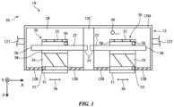
- FIG. 1 is a schematic diagram of an illustrative electronic device of the type that may include movable components.
- Device 10 of FIG. 1 may be a head-mounted device (e.g., goggles, glasses, a helmet, and/or other head-mounted device), a cellular telephone, a tablet computer, a laptop computer, a wristwatch, a peripheral device (sometimes referred to as a peripheral) such as a pair of headphones, or other electronic equipment.
- device 10 is a head-mounted device such as a pair of goggles (sometimes referred to as virtual reality goggles, mixed reality goggles, augmented reality glasses, etc.).
- device 10 may have a housing such as housing 12 (sometimes referred to as a head-mounted support structure or head-mounted support).
- Housing 12 may include a main portion such as portion 12M (sometimes referred to as a main unit or head-mounted unit) and other head-mounted support structures such as head strap 12T.
- portion 12M sometimes referred to as a main unit or head-mounted unit
- head strap 12T head strap
- Device 10 may have electrical and optical components that are used in displaying images to eye boxes 36 when device 10 is being worn. These components may include left and right optical assemblies 20 (sometimes referred to as optical modules). Each optical assembly 20 may have an optical assembly support 38 (sometimes referred to as a lens barrel or optical module support) and guide rails 22 along which optical assemblies 20 may slide to adjust optical-assembly-to-optical-assembly separation to accommodate different user interpupillary distances.
- optical assembly support 38 sometimes referred to as a lens barrel or optical module support
- guide rails 22 along which optical assemblies 20 may slide to adjust optical-assembly-to-optical-assembly separation to accommodate different user interpupillary distances.
- Each assembly 20 may have a display 32 that has an array of pixels for displaying images and a lens 34.
- Display 32 and lens 34 of each assembly 20 may be coupled to and supported by support 38.
- images displayed by displays 32 may be presented to eye boxes 36 through lenses 34 for viewing by a user.
- Each optical assembly 20 may also have a gaze tracker 50.
- Gaze trackers 50 may each include one or more light sources (e.g., infrared light-emitting diodes that provide flood illumination and glints for eye tracking) and an associated camera (e.g., an infrared camera).
- gaze trackers 50 which may sometimes be referred to as gaze tracking systems or gaze tracking sensors, device 10 can gather data on a user's eyes located in eye boxes 36.
- gaze trackers 50 may be used to measure the location of a user's eyes relative to device 10 and thereby measure the eye relief of the user's eyes (e.g., the distance between the lenses of device 10 and the eyes) and the separation between the user's left and right eyes (sometimes referred to as the user's interpupillary distance). If desired, gaze trackers 50 (e.g., the cameras of trackers 50) may capture images of the skin of the user's face surrounding the user's eyes (e.g., to measure whether this skin is loose or taut).
- Each optical assembly may have magnets, clips, and/or other engagement features to allow removable vision correction lenses (sometimes referred to as prescription lenses) to be removably attached to assemblies 20 in alignment with lenses 34 (see, e.g., illustrative optional vision correction lenses 51).
- Lenses 51 may have magnets that are sensed by sensors 53 (e.g., magnetic sensors in assemblies 20) or sensors 53 may be optical sensors, switches, or other sensors configured to gather other information indicating when lenses 51 are present.
- Housing 12 may have a flexible curtain (sometimes referred to as a flexible rear housing wall or fabric housing wall) such as curtain 12R on the rear of device 10 facing eye boxes 36.
- Curtain 12R has openings that receive assemblies 20.
- the edges of curtain 12R that surround each support 38 may be coupled to that support 38.
- the outer peripheral edge of curtain 12R may be attached to rigid housing walls forming an outer shell portion of main housing 12M.
- housing 12 may separate interior region 28 within device 10 from exterior region 30 surrounding device 10.
- Inner ends 24 of guide rails 22 may be attached to central housing portion 12C.
- Opposing outer ends 26 may, in an illustrative configuration, be unsupported (e.g., the outer end portions of rails 22 may not directly contact housing 12, so that these ends float in interior region 28 with respect to housing 12).
- Device 10 may include control circuitry and other components such as component 40.
- the control circuitry may include storage, processing circuitry formed from one or more microprocessors and/or other circuits.
- the control circuitry may include wireless communications circuitry.
- Components 40 may include sensors such as such as force sensors (e.g., strain gauges, capacitive force sensors, resistive force sensors, etc.), audio sensors such as microphones, touch and/or proximity sensors such as capacitive sensors, optical sensors such as optical sensors that emit and detect light, ultrasonic sensors, and/or other touch sensors and/or proximity sensors, monochromatic and color ambient light sensors, image sensors, sensors for detecting position, orientation, and/or motion (e.g., accelerometers, magnetic sensors such as compass sensors, gyroscopes, and/or sensors such as inertial measurement units that contain some or all of these sensors), radio-frequency sensors, depth sensors (e.g., structured light sensors and/or depth sensors based on stereo imaging devices), optical sensors such as self-mix
- devices 10 may use sensors to gather user input (e.g., button press input, touch input, etc.). Sensors may also be used in gathering environmental motion (e.g., device motion measurements, temperature measurements, ambient light readings, etc.) and/or may be used in measuring user activities and/or attributes (e.g., point-of-gaze, eye relief, interpupillary distance, etc.). If desired, position sensors such as encoders (e.g., optical encoders, magnetic encoders, etc.) may measure the position and therefore the movement (e.g., the velocity, acceleration, etc.) of optical assemblies 20 along rails 22.
- encoders e.g., optical encoders, magnetic encoders, etc.
- FIG. 2 is a rear view of an illustrative portion of device 10 (e.g., an inside left portion).
- Device 10 may have left and right actuators (e.g., motors) such as motor 48 that are used to rotate an elongated threaded shaft such as screw 44.
- Nut 46 has threads that engage the threads on screw 44.
- the motor 48 on each side of device 10 is turned, a corresponding nut 46 is driven in the +X or -X direction (in accordance with whether screw 44 is being rotated clockwise or counterclockwise). In turn, this moves the optical assembly 20 on that side of device 10 in the +X or -X direction along its optical assembly guide rail 22.
- the left and right motors 48 may be adjusted independently, so that optical assemblies 20 on the left and right of device 10 may be moved independently.
- Each assembly 20 may have portions that receive a corresponding rail 22 and that guide that assembly 20 along that rail 22.
- the spacing between the left and right optical assemblies of device 10 can be adjusted to accommodate the interpupillary distance of different users. For example, if gaze trackers 50 determine that a user has closely spaced eyes, assemblies 20 may be moved inwardly (towards each other) and if a user has widely spaced eyes, assemblies 20 may be moved outwardly (away from each other).
- the spacing between optical assemblies 20 to the measured interpupillary distance of a user, the user may satisfactorily view visual content being presented by the displays of the optical assemblies.
- each optical assembly may be monitored using one or more sensors.
- motor 48 e.g., the motor on the left side of device 10
- optical module 20 have been provided with an optical assembly position sensor based on a magnetic encoder.
- the encoder includes magnetic strip 54 and magnetic sensor 52.
- Magnetic sensor 52 may be a Hall Effect sensor or other suitable magnetic sensor that is configured to move with optical assembly 20.
- Magnetic strip 54 which may be affixed to housing 12, has a series of magnet poles (e.g., north and south poles) that extend along the X dimension parallel to guide rail 22 and parallel to the X-axis position adjustment direction associated with optical assembly 20.
- the magnetic encoder e.g., sensor 52
- the magnetic encoder measures the change in magnetic field resulting as magnetic sensor 52 passes by different magnets in strip 54.
- optical assembly 20 is provided with a position reference (e.g., by counting north and south magnetic poles in strip 54).
- the position measurements made with the position sensor may reveal attributes of the motion of optical assembly 20 such as the velocity of optical assembly 20 and, if desired, the acceleration and deceleration of assembly 20.
- the magnetic encoder (or other position sensor) associated with each optical assembly 30 may be used by device 10 to measure the location of that optical assembly so that the spacing between optical assemblies 20 can be satisfactorily adjusted (e.g., to help ensure that the spacing between optical assemblies 20 has been adjusted to match or nearly match the user's interpupillary distance).
- the position readings from the optical assembly position sensors may also be used to determine the velocities of the optical assemblies as they are moved.
- FIG. 3 is a rear view of a central nose-bridge portion NB of device 10.
- nose bridge portion NB of housing portion 12C has a nose-shaped recess 60, which is configured to receive the user's nose (see, e.g., illustrative nose surface 62).
- optical assemblies 20 reside at a non-zero distance G from surface 62 (sometimes referred to as gap G) after motors 48 adjusted the positions of assemblies 20 to match the user's interpupillary distance.
- motors 48 may move optical assemblies inward until curtain 12R ( FIG. 1 ) and optical assemblies 20 contact the left and right sides of nose surface 62.
- optical assemblies 20 When optical assemblies 20 contact the left and right sides of nose surface of 62, motors 48 will encounter resistance to further lateral movement of the optical assemblies along the X axis. This will cause optical assemblies 20 to move more slowly.
- the optical assembly position sensors will sense the reduction in the velocity of the optical assemblies. In this way, device 10 is informed that optical assemblies 20 are contacting and pressing against nose surface 62.
- the position of the optical assemblies may, in response to this detected nose contact, be adjusted outward, away from nose surface 62 (e.g., by 1-3 mm or other suitable amount). This outward nudge in the positions of the optical assemblies may be made even if the final separation between the optical assemblies is slightly larger than the user's measured interpupillary distance.
- a non-zero gap G may be created between optical assemblies 20 and corresponding side portions of the user's nose (e.g., adjacent portions of nose surface 62) and/or inward pressure imposed on the sides of the user's nose by optical assemblies 20 can be reduced to enhance comfort.
- device 10 can identify a location for assemblies 20 in which the left and right assemblies 20 are separated by distance that is matched as closely as possible to the user's measured interpupillary distance while ensuring satisfactory comfort for the user.
- gaze trackers 50 may measure the user's interpupillary distance and may measure the user's eye relief. Motors 48 may then adjust the positions of optical assemblies 20 based on the measured eye relief and measured interpupillary distance of the user.
- the positions of optical assemblies 20 maybe offset (e.g., nudged outwards from the location where the spacing between assemblies 20 matches the measured interpupillary distance of the user) by an amount that varies depending on both measured interpupillary distance and measured eye relief.
- lateral offset ⁇ X represents the distance by which an optical assembly is adjusted outwardly (beyond the nominal position in which optical assembly separation matches measured interpupillary distance) to enhance fit.
- lateral offset ⁇ X represents the distance by which an optical assembly is adjusted outwardly (beyond the nominal position in which optical assembly separation matches measured interpupillary distance) to enhance fit.
- Curve 64 corresponds to a measured interpupillary distance IPDA
- curve 66 corresponds to a measured interpupillary distance IPDB, which is larger than interpupillary distance IPDA
- curve 68 corresponds to a measured interpupillary distance IPDC, which is larger than interpupillary distance IPDA and larger than interpupillary distance IPDB.
- IPDA, IPDB, and IPDC may be in the range of 52 to 74 mm or any other suitable range.
- device 10 may store a family of curves (e.g., empirically determined curves) for any suitable number of measured interpupillary distances and/or may represent the relationships embodied in curves such as curves 64, 66, and 68 using tables, functions, and/or other data structures.
- a predetermined threshold e.g., ERTH in the example of FIG. 4
- the user is unlikely to experience pressure from optical assemblies 20 on the sides of the user's nose.
- optical assemblies 20 may be separated along the X axis by a distance that matches the measured interpupillary distance of the user (e.g., there is no need to use a non-zero value of ⁇ X to adjust the position of optical assemblies 20 outwardly after they have reached the appropriate spacing to match the user's interpupillary distance).
- the value of ⁇ X is therefore zero for users with measured eye relief values of less than ERTH (which may be, for example, a value between 18 mm and 22 mm or other suitable eye relief threshold value).
- the measured eye relief of a user exceeds eye relief threshold ERTH, it may be beneficial for certain users to increase the spacing between optical assemblies 20 by nudging each optical assembly outwardly by an amount ⁇ X.
- ⁇ X the spacing between optical assemblies 20 by nudging each optical assembly outwardly by an amount ⁇ X.
- ⁇ X may be zero for measured eye relief values of less than ERTH, whereas for measured eye relief values exceeding ERTH, ⁇ X may rise progressively as a function of measured eye relief (e.g., up to a maximum ⁇ X value at a maximum measured eye relief value of ERMX, which may be, for example, 25 mm or other suitable value).
- Users with larger interpupillary distances, such as a measured interpupillary distance of IPDB may benefit from a less aggressive outward increase in optical assembly spacing, as shown by curve 66 in which the value of ⁇ X rises more slowly as a function of increasing measured eye relief over ERTH than curve 64.
- An interpupillary distance threshold may be present above which it may not be desirable to make any ⁇ X adjustments for a user, regardless of their measured eye relief.
- a user has a large measured interpupillary distance (e.g., a measured interpupillary distance of IPDC, which exceeds the interpupillary distance threshold)
- a measured interpupillary distance of IPDC which exceeds the interpupillary distance threshold
- the recommended outward adjustment in optical assembly position ⁇ X as a function of measured eye relief for users with these larger measured interpupillary distances follows curve 68 (e.g., ⁇ X remains at zero, even for a measured eye relief of ERMX).
- the graph of FIG. 4 illustrates how motors 48 may place optical assemblies 20 at positions that vary from the measured positions of the user's eyes.
- measured eye relief and interpupillary distance values were used in determining satisfactory positions for assemblies 20.
- outward adjustments ⁇ X in the positions of optical assemblies 20 were recommended as a function of the interpupillary distance and eye relief values measured for a user with gaze trackers 50.
- additional factors may be taken into consideration in making optical assembly adjustments such as these (e.g., additional factors that may be used in combination with or as an alternative to using interpupillary distance measurements and eye relief measurements) and/or other suitable action may be taken based on data gathered with gaze trackers 50 and/or other sensors in device 10.
- FIG. 5 is a flow chart illustrating operations involved in using motors 48 and other components in device 10 to make adjustments to device 10 as a function of data gathered with gaze trackers 50 and/or other sensors.
- device 10 may gather data.
- the gathered data may include, for example, measurements obtained by gaze trackers 50. These measurements may include, for example, the measured interpupillary distance of a user wearing device 10, the measured eye relief of a user wearing device 10, the measured skin tautness around the eyes of a user wearing device 10, and/or other gaze tracker measurements.
- the measurements of block 70 may also include measurements with the position sensors (e.g., the magnetic encoders) of optical assemblies 20. For example, when a user dons device 10, motors 48 may automatically start to move optical assemblies 20 to positions associated with the user's measured interpupillary distance from gaze trackers 50.
- the position sensors may be used to monitor the velocities of assemblies 20.
- device 10 can conclude that assemblies 20 are beginning to exert pressure on the sides of the user's nose (e.g., nose surface 62).
- the locations associated with the measured reduction in optical assembly velocity are another form of measurement data that may be gathered during block 70.
- Vision correction lenses 51 may contain magnets that produce a magnetic field.
- Device 10 e.g., assemblies 20
- vision correction lens sensors such as magnetic sensors 53 that determine whether or not lenses 51 are present by monitoring for the presence of the magnetic fields produced by lenses 51. In response to detection of the magnetic fields from lenses 51 with sensors 53, it can be concluded that lenses 51 are present.
- device 10 can take action based on the data gathered at block 70.
- the positions of optical assemblies 20 may be adjusted using motors 48.
- the positions of optical assemblies 20 may be nudged outwards by an amount ⁇ X determined from measured interpupillary distance and eye relief values, as described in connection with FIG. 4 .
- optical assemblies 20 may, in some scenarios, be moved inward slightly (e.g., assemblies 20 may be moved towards each other such that assemblies 20 are closer than dictated by the measured value of a user's interpupillary distance to increase nasal field-of-view overlap when doing so presents a low risk of optical assembly nose surface contact or when any potential nose contact can be detected with an optical module position sensor or other sensor).
- optical assemblies 20 may be moved inwards or outwards slightly to tighten curtain 12R.
- Optical assembly movement with motors 48 may also be used to provide a user with an alert (e.g., a haptic alert indicating that an incoming message has been received and/or another condition has been determined to be present).
- gaze sensor measurements from trackers 50 during block 70 can be used to determine whether the user's skin surrounding the user's eyes is taut.
- assemblies 20 In response to detecting an increase in skin tautness as assemblies 20 are moved (e.g., as assemblies 20 are being moved towards each other), it can be concluded that assemblies 20 are pressing or are about to press on nose surface 62, so further movement inward of assemblies 20 can be halted and/or assemblies 20 may be nudged outwardly to compensate.
- the positions of optical assemblies 20 may also be adjusted in response to detection that vision correction lenses 51 are present or are not present.
- the presence of lenses 51 may, as an example, increase or decrease the risk of nose contact by assemblies 20, so information on the presence of lenses 51 (and, if desired, the prescription associated with lenses 51) may be taken into account when using motors 48 to adjust the position of assemblies 20.
- these types of adjustments and/or other suitable actions may be taken during the operations of block 72 in response to gaze tracker measurement data and/or other data measured during the operations of block 70.
- any personal user information that is gathered by sensors may be handled using best practices. These best practices including meeting or exceeding any privacy regulations that are applicable. Opt-in and opt-out options and/or other options may be provided that allow users to control usage of their personal data.
- a head-mounted device in accordance with an aspect of the invention, includes a head-mounted housing, an optical assembly in the head-mounted housing that is configured to provide an image to an eye box, a gaze tracker and a motor configured to position the optical assembly based on a measured eye relief from the gaze tracker and a measured interpupillary distance from the gaze tracker.
- the motor is configured to move the optical assembly outward from a central portion of the head-mounted housing in response to determining that the measured eye relief is more than a predetermined threshold amount.
- the motor is configured to adjust the position of the optical assembly outwards by a first amount in response to determining that the measured eye relief has an eye relief value that is more than a predetermined threshold amount and that the measured interpupillary distance has a first value and is configured to move the optical assembly outwards by a second amount that is more than the first amount in response to determining that the measured eye relief has the eye relief value and that the measured interpupillary distance has a second value that is less than the first value.
- the head-mounted device includes a vision correction lens sensor
- the motor is further configured to position the optical assembly based on information from the vision correction lens sensor.
- the optical assembly is configured to receive a removable vision correction lens with a magnet that produces a magnetic field and the motor is further configured to position the optical assembly based on information from the magnetic sensor.
- the motor is configured to provide a haptic alert by moving the optical assembly.
- the gaze tracker is configured to measure skin tautness.
- the motor is further configured to adjust the position of the optical assembly based on the measured skin tautness.
- a head-mounted device in accordance with an aspect of the invention, includes a head-mounted housing, left and right optical assemblies in the head-mounted housing that are separated by a separation distance and that are configured to provide respective left and right images to left and right eye boxes, a left gaze tracker in the left optical assembly, a right gaze tracker in the right optical assembly, the left and right gaze trackers are configured to measure an interpupillary distance and an eye relief and left and right motors configured to respectively position the left and right optical assemblies, the left and right motors are configured to adjust the separation distance to be different than the measured interpupillary distance based on the measured eye relief.
- the left and right motors are configured to adjust the separation distance to be greater than the measured interpupillary distance based on the measured eye relief exceeding a predetermined eye relief threshold.
- the left and right motors are configured to adjust the separation distance to be greater than the measured interpupillary distance based on the measured interpupillary distance.
- the left and right motors are configured to adjust the separation distance to be greater than the measured interpupillary distance based on the measured interpupillary distance being below a predetermined interpupillary distance threshold.
- the head-mounted device includes a vision correction lens presence sensor
- the left and right motors are configured to adjust the separation distance based on information from the vision correction lens presence sensor.
- the left and right optical assemblies are configured to receive left and right vision correction lenses, respectively, and the vision correction lens presence sensor includes a magnetic sensor configured to measure a magnetic field from the left or right vision correction lens.
- the left and right gaze trackers are configured to measure skin tautness.
- the left and right motors are configured to adjust the separation distance to be greater than the measured interpupillary distance based on the measured skin tautness.
- a head-mounted device includes an optical assembly having a lens, a display configured to display an image to an eye box through the lens, and a gaze tracker configured to make an interpupillary distance measurement and an eye relief measurement through the lens and a motor configured to adjust a position of the optical assembly based on the eye relief measurement.
- the head-mounted device includes a head-mounted housing and a guide rail in the head-mounted housing along which the optical assembly slides, the motor is configured to adjust the position of the optical assembly by moving the optical assembly along the rail based on the eye relief measurement.
- the motor is configured to adjust the position of the optical assembly based on the interpupillary distance measurement.
- the motor is configured to adjust the position of the optical assembly outwardly away from a center portion of the head-mounted housing based on the interpupillary distance measurement and the eye relief measurement.
Landscapes
- Physics & Mathematics (AREA)
- General Physics & Mathematics (AREA)
- Optics & Photonics (AREA)
- Eye Examination Apparatus (AREA)
Abstract
Description
- This application claims priority to
U.S. patent application No. 18/351,296, filed July 12, 2023 U.S. provisional patent application No. 63/406,902, filed September 15, 2022 - This relates generally to electronic devices, and, more particularly, to electronic devices such as head-mounted devices.
- Electronic devices have components such as displays. The positions of these components may sometimes be adjusted.
- A head-mounted device may include optical assemblies with displays for presenting images to a user. Motors may be used to adjust the spacing between the optical assemblies and thereby adjust the spacing between the displays to accommodate different interpupillary distances.
- The optical assemblies may have gaze trackers. The gaze trackers may be used to make interpupillary distance measurements and eye relief measurements. Adjustments to the positions of the optical assemblies may be made by the motors based on the interpupillary distance measurements and eye relief measurements. For example, no position adjustments may be made unless a measured eye relief measurement exceeds an eye relief threshold and the measured interpupillary distance is lower than an interpupillary distance threshold . If the measured eye relief measurement is sufficiently large and the measured interpupillary distance is sufficiently small, adjustments to the positions of the optical assemblies may be made in which, for a given measured eye relief, a smaller measured interpupillary distance results in a larger adjustment to an optical assembly position than a larger measured interpupillary distance.
-
-
FIG. 1 is a diagram of an illustrative head-mounted device in accordance with an embodiment. -
FIGS. 2 and3 are rear views of portions of illustrative head-mounted devices in accordance with embodiments. -
FIG. 4 is a graph in which illustrative optical assembly adjustment values are plotted as a function of measured eye relief for multiple different illustrative measured interpupillary distances in accordance with an embodiment. -
FIG. 5 is a flow chart of illustrative operations involved in using a head-mounted device in accordance with an embodiment. -
FIG. 1 is a schematic diagram of an illustrative electronic device of the type that may include movable components.Device 10 ofFIG. 1 may be a head-mounted device (e.g., goggles, glasses, a helmet, and/or other head-mounted device), a cellular telephone, a tablet computer, a laptop computer, a wristwatch, a peripheral device (sometimes referred to as a peripheral) such as a pair of headphones, or other electronic equipment. In an illustrative configuration,device 10 is a head-mounted device such as a pair of goggles (sometimes referred to as virtual reality goggles, mixed reality goggles, augmented reality glasses, etc.). - As shown in the illustrative top view of
device 10 ofFIG. 1 ,device 10 may have a housing such as housing 12 (sometimes referred to as a head-mounted support structure or head-mounted support).Housing 12 may include a main portion such asportion 12M (sometimes referred to as a main unit or head-mounted unit) and other head-mounted support structures such ashead strap 12T. Whenhousing 12 is being worn on the head of a user, the front ofhousing 12 may face outwardly away from the user, the rear ofhousing 12 may face towards the user, and the user's eyes may be located ineye boxes 36. -
Device 10 may have electrical and optical components that are used in displaying images toeye boxes 36 whendevice 10 is being worn. These components may include left and right optical assemblies 20 (sometimes referred to as optical modules). Eachoptical assembly 20 may have an optical assembly support 38 (sometimes referred to as a lens barrel or optical module support) andguide rails 22 along whichoptical assemblies 20 may slide to adjust optical-assembly-to-optical-assembly separation to accommodate different user interpupillary distances. - Each
assembly 20 may have adisplay 32 that has an array of pixels for displaying images and alens 34.Display 32 andlens 34 of eachassembly 20 may be coupled to and supported bysupport 38. During operation, images displayed bydisplays 32 may be presented toeye boxes 36 throughlenses 34 for viewing by a user. Eachoptical assembly 20 may also have agaze tracker 50.Gaze trackers 50 may each include one or more light sources (e.g., infrared light-emitting diodes that provide flood illumination and glints for eye tracking) and an associated camera (e.g., an infrared camera). Usinggaze trackers 50, which may sometimes be referred to as gaze tracking systems or gaze tracking sensors,device 10 can gather data on a user's eyes located ineye boxes 36. As an example, the direction in which a user's eyes are pointing (sometimes referred to as a user's point of gaze or direction of view) may be measured. Biometric information such as iris scan information may also be gathered. In addition,gaze trackers 50, may be used to measure the location of a user's eyes relative todevice 10 and thereby measure the eye relief of the user's eyes (e.g., the distance between the lenses ofdevice 10 and the eyes) and the separation between the user's left and right eyes (sometimes referred to as the user's interpupillary distance). If desired, gaze trackers 50 (e.g., the cameras of trackers 50) may capture images of the skin of the user's face surrounding the user's eyes (e.g., to measure whether this skin is loose or taut). - Each optical assembly may have magnets, clips, and/or other engagement features to allow removable vision correction lenses (sometimes referred to as prescription lenses) to be removably attached to assemblies 20 in alignment with lenses 34 (see, e.g., illustrative optional vision correction lenses 51).
Lenses 51 may have magnets that are sensed by sensors 53 (e.g., magnetic sensors in assemblies 20) orsensors 53 may be optical sensors, switches, or other sensors configured to gather other information indicating whenlenses 51 are present. -
Housing 12 may have a flexible curtain (sometimes referred to as a flexible rear housing wall or fabric housing wall) such ascurtain 12R on the rear ofdevice 10 facingeye boxes 36. Curtain 12R has openings that receiveassemblies 20. The edges ofcurtain 12R that surround eachsupport 38 may be coupled to that support 38. The outer peripheral edge ofcurtain 12R may be attached to rigid housing walls forming an outer shell portion ofmain housing 12M. - The walls of
housing 12 may separateinterior region 28 withindevice 10 fromexterior region 30 surroundingdevice 10. -
Inner ends 24 ofguide rails 22 may be attached tocentral housing portion 12C. Opposingouter ends 26 may, in an illustrative configuration, be unsupported (e.g., the outer end portions ofrails 22 may not directly contacthousing 12, so that these ends float ininterior region 28 with respect to housing 12). -
Device 10 may include control circuitry and other components such ascomponent 40. The control circuitry may include storage, processing circuitry formed from one or more microprocessors and/or other circuits. To support communications betweendevice 10 and external equipment, the control circuitry may include wireless communications circuitry.Components 40 may include sensors such as such as force sensors (e.g., strain gauges, capacitive force sensors, resistive force sensors, etc.), audio sensors such as microphones, touch and/or proximity sensors such as capacitive sensors, optical sensors such as optical sensors that emit and detect light, ultrasonic sensors, and/or other touch sensors and/or proximity sensors, monochromatic and color ambient light sensors, image sensors, sensors for detecting position, orientation, and/or motion (e.g., accelerometers, magnetic sensors such as compass sensors, gyroscopes, and/or sensors such as inertial measurement units that contain some or all of these sensors), radio-frequency sensors, depth sensors (e.g., structured light sensors and/or depth sensors based on stereo imaging devices), optical sensors such as self-mixing sensors and light detection and ranging (lidar) sensors that gather time-of-flight measurements, humidity sensors, moisture sensors, visual inertial odometry sensors, gaze tracking sensors, and/or other sensors. In some arrangements,devices 10 may use sensors to gather user input (e.g., button press input, touch input, etc.). Sensors may also be used in gathering environmental motion (e.g., device motion measurements, temperature measurements, ambient light readings, etc.) and/or may be used in measuring user activities and/or attributes (e.g., point-of-gaze, eye relief, interpupillary distance, etc.). If desired, position sensors such as encoders (e.g., optical encoders, magnetic encoders, etc.) may measure the position and therefore the movement (e.g., the velocity, acceleration, etc.) ofoptical assemblies 20 alongrails 22. -
FIG. 2 is a rear view of an illustrative portion of device 10 (e.g., an inside left portion).Device 10 may have left and right actuators (e.g., motors) such asmotor 48 that are used to rotate an elongated threaded shaft such asscrew 44.Nut 46 has threads that engage the threads onscrew 44. As themotor 48 on each side ofdevice 10 is turned, acorresponding nut 46 is driven in the +X or -X direction (in accordance with whetherscrew 44 is being rotated clockwise or counterclockwise). In turn, this moves theoptical assembly 20 on that side ofdevice 10 in the +X or -X direction along its opticalassembly guide rail 22. If desired, the left andright motors 48 may be adjusted independently, so thatoptical assemblies 20 on the left and right ofdevice 10 may be moved independently. - Each assembly 20 (e.g., each
support 38 ofFIG. 1 ) may have portions that receive acorresponding rail 22 and that guide thatassembly 20 along thatrail 22. By controlling the activity ofmotors 48 in tandem or individually, the spacing between the left and right optical assemblies ofdevice 10 can be adjusted to accommodate the interpupillary distance of different users. For example, ifgaze trackers 50 determine that a user has closely spaced eyes,assemblies 20 may be moved inwardly (towards each other) and if a user has widely spaced eyes,assemblies 20 may be moved outwardly (away from each other). By matching the spacing betweenoptical assemblies 20 to the measured interpupillary distance of a user, the user may satisfactorily view visual content being presented by the displays of the optical assemblies. - The position and therefore the movement of each optical assembly may be monitored using one or more sensors. In the illustrative configuration of
FIG. 2 , motor 48 (e.g., the motor on the left side of device 10) andoptical module 20 have been provided with an optical assembly position sensor based on a magnetic encoder. The encoder includesmagnetic strip 54 andmagnetic sensor 52.Magnetic sensor 52 may be a Hall Effect sensor or other suitable magnetic sensor that is configured to move withoptical assembly 20.Magnetic strip 54, which may be affixed tohousing 12, has a series of magnet poles (e.g., north and south poles) that extend along the X dimension parallel to guiderail 22 and parallel to the X-axis position adjustment direction associated withoptical assembly 20. Asoptical assembly 20 is moved alongguide rail 22, the magnetic encoder (e.g., sensor 52) measures the change in magnetic field resulting asmagnetic sensor 52 passes by different magnets instrip 54. In this way,optical assembly 20 is provided with a position reference (e.g., by counting north and south magnetic poles in strip 54). The position measurements made with the position sensor may reveal attributes of the motion ofoptical assembly 20 such as the velocity ofoptical assembly 20 and, if desired, the acceleration and deceleration ofassembly 20. Accordingly, the magnetic encoder (or other position sensor) associated with eachoptical assembly 30 may be used bydevice 10 to measure the location of that optical assembly so that the spacing betweenoptical assemblies 20 can be satisfactorily adjusted (e.g., to help ensure that the spacing betweenoptical assemblies 20 has been adjusted to match or nearly match the user's interpupillary distance). The position readings from the optical assembly position sensors (e.g., the magnetic encoders) may also be used to determine the velocities of the optical assemblies as they are moved. - Optical assembly velocity information and/or other information from the optical assembly position sensors (e.g., linear position sensors formed from the magnetic encoders) may be used in monitoring whether the optical assemblies have slowed down their movement due to contact between the optical assemblies and the nose of a user. Consider, as an example, the arrangement of
FIG. 3. FIG. 3 is a rear view of a central nose-bridge portion NB ofdevice 10. As shown inFIG. 3 , nose bridge portion NB ofhousing portion 12C has a nose-shapedrecess 60, which is configured to receive the user's nose (see, e.g., illustrative nose surface 62). In some situations (e.g., when a user has a wide interpupillary distance),optical assemblies 20 reside at a non-zero distance G from surface 62 (sometimes referred to as gap G) aftermotors 48 adjusted the positions ofassemblies 20 to match the user's interpupillary distance. In other situations, such as when a user has a large eye relief and small interpupillary distance,motors 48 may move optical assemblies inward untilcurtain 12R (FIG. 1 ) andoptical assemblies 20 contact the left and right sides ofnose surface 62. - When
optical assemblies 20 contact the left and right sides of nose surface of 62,motors 48 will encounter resistance to further lateral movement of the optical assemblies along the X axis. This will causeoptical assemblies 20 to move more slowly. The optical assembly position sensors will sense the reduction in the velocity of the optical assemblies. In this way,device 10 is informed thatoptical assemblies 20 are contacting and pressing againstnose surface 62. To ensure thatdevice 10 is comfortable asdevice 10 is being worn on the head of the user, the position of the optical assemblies may, in response to this detected nose contact, be adjusted outward, away from nose surface 62 (e.g., by 1-3 mm or other suitable amount). This outward nudge in the positions of the optical assemblies may be made even if the final separation between the optical assemblies is slightly larger than the user's measured interpupillary distance. - Following outward adjustment of
optical assemblies 20, a non-zero gap G may be created betweenoptical assemblies 20 and corresponding side portions of the user's nose (e.g., adjacent portions of nose surface 62) and/or inward pressure imposed on the sides of the user's nose byoptical assemblies 20 can be reduced to enhance comfort. By monitoring the optical assembly position sensors during optical assembly position adjustment withmotors 48,device 10 can identify a location forassemblies 20 in which the left andright assemblies 20 are separated by distance that is matched as closely as possible to the user's measured interpupillary distance while ensuring satisfactory comfort for the user. - Another way in which the position of
optical assemblies 20 can be adjusted satisfactorily involves the use of eye relief measurements fromgaze trackers 50. Whendevice 10 is placed onto the head of the user, gazetrackers 50 may measure the user's interpupillary distance and may measure the user's eye relief.Motors 48 may then adjust the positions ofoptical assemblies 20 based on the measured eye relief and measured interpupillary distance of the user. In an illustrative configuration, the positions ofoptical assemblies 20 maybe offset (e.g., nudged outwards from the location where the spacing betweenassemblies 20 matches the measured interpupillary distance of the user) by an amount that varies depending on both measured interpupillary distance and measured eye relief. - This type of approach is illustrated in the graph of
FIG. 4 . In the graph ofFIG. 4 , lateral offset ΔX represents the distance by which an optical assembly is adjusted outwardly (beyond the nominal position in which optical assembly separation matches measured interpupillary distance) to enhance fit. There are three illustrative curves in the graph ofFIG. 4 .Curve 64 corresponds to a measured interpupillary distance IPDA,curve 66 corresponds to a measured interpupillary distance IPDB, which is larger than interpupillary distance IPDA, andcurve 68 corresponds to a measured interpupillary distance IPDC, which is larger than interpupillary distance IPDA and larger than interpupillary distance IPDB. The values of IPDA, IPDB, and IPDC may be in the range of 52 to 74 mm or any other suitable range. In practice,device 10 may store a family of curves (e.g., empirically determined curves) for any suitable number of measured interpupillary distances and/or may represent the relationships embodied in curves such ascurves - As the graph of a
FIG. 4 illustrates, if the measured eye relief a user falls below a predetermined threshold (e.g., ERTH in the example ofFIG. 4 ), the user is unlikely to experience pressure fromoptical assemblies 20 on the sides of the user's nose. Accordingly, for measured user eye relief values below eye relief threshold ERTH,optical assemblies 20 may be separated along the X axis by a distance that matches the measured interpupillary distance of the user (e.g., there is no need to use a non-zero value of ΔX to adjust the position ofoptical assemblies 20 outwardly after they have reached the appropriate spacing to match the user's interpupillary distance). The value of ΔX is therefore zero for users with measured eye relief values of less than ERTH (which may be, for example, a value between 18 mm and 22 mm or other suitable eye relief threshold value). - If, however, the measured eye relief of a user exceeds eye relief threshold ERTH, it may be beneficial for certain users to increase the spacing between
optical assemblies 20 by nudging each optical assembly outwardly by an amount ΔX. As an example, consider users with measured interpupillary distances of IPDA. For this class of user, it may be beneficial to adjust the spacing ofoptical assemblies 20 outwardly by ΔX values that followcurve 64. As shown bycurve 64, ΔX may be zero for measured eye relief values of less than ERTH, whereas for measured eye relief values exceeding ERTH, ΔX may rise progressively as a function of measured eye relief (e.g., up to a maximum ΔX value at a maximum measured eye relief value of ERMX, which may be, for example, 25 mm or other suitable value). Users with larger interpupillary distances, such as a measured interpupillary distance of IPDB, may benefit from a less aggressive outward increase in optical assembly spacing, as shown bycurve 66 in which the value of ΔX rises more slowly as a function of increasing measured eye relief over ERTH thancurve 64. - An interpupillary distance threshold may be present above which it may not be desirable to make any ΔX adjustments for a user, regardless of their measured eye relief. When, for example, a user has a large measured interpupillary distance (e.g., a measured interpupillary distance of IPDC, which exceeds the interpupillary distance threshold), there will generally not be a comfort benefit in increasing optical assembly spacing. As a result, the recommended outward adjustment in optical assembly position ΔX as a function of measured eye relief for users with these larger measured interpupillary distances follows curve 68 (e.g., ΔX remains at zero, even for a measured eye relief of ERMX). With this approach, only at measured interpupillary distances below the interpupillary distance threshold will outward adjustments in optical assembly position be used.
- The graph of
FIG. 4 illustrates howmotors 48 may placeoptical assemblies 20 at positions that vary from the measured positions of the user's eyes. In the example ofFIG. 4 , measured eye relief and interpupillary distance values were used in determining satisfactory positions forassemblies 20. In particular, outward adjustments ΔX in the positions ofoptical assemblies 20 were recommended as a function of the interpupillary distance and eye relief values measured for a user withgaze trackers 50. If desired, additional factors may be taken into consideration in making optical assembly adjustments such as these (e.g., additional factors that may be used in combination with or as an alternative to using interpupillary distance measurements and eye relief measurements) and/or other suitable action may be taken based on data gathered withgaze trackers 50 and/or other sensors indevice 10. -
FIG. 5 is a flow chart illustrating operations involved in usingmotors 48 and other components indevice 10 to make adjustments todevice 10 as a function of data gathered withgaze trackers 50 and/or other sensors. - During the operations of
block 70,device 10 may gather data. The gathered data may include, for example, measurements obtained bygaze trackers 50. These measurements may include, for example, the measured interpupillary distance of auser wearing device 10, the measured eye relief of auser wearing device 10, the measured skin tautness around the eyes of auser wearing device 10, and/or other gaze tracker measurements. The measurements ofblock 70 may also include measurements with the position sensors (e.g., the magnetic encoders) ofoptical assemblies 20. For example, when a user donsdevice 10,motors 48 may automatically start to moveoptical assemblies 20 to positions associated with the user's measured interpupillary distance fromgaze trackers 50. During this initial movement or during movement in response to a user input command or other movement, the position sensors may be used to monitor the velocities ofassemblies 20. In response to detected slowing of the speed of inward movement ofassemblies 20,device 10 can conclude thatassemblies 20 are beginning to exert pressure on the sides of the user's nose (e.g., nose surface 62). The locations associated with the measured reduction in optical assembly velocity are another form of measurement data that may be gathered duringblock 70. - Further information that can be gathered during the operations of
block 70 relates to the status ofvision correction lenses 51 ondevice 10.Vision correction lenses 51 may contain magnets that produce a magnetic field. Device 10 (e.g., assemblies 20) may have vision correction lens sensors such asmagnetic sensors 53 that determine whether or notlenses 51 are present by monitoring for the presence of the magnetic fields produced bylenses 51. In response to detection of the magnetic fields fromlenses 51 withsensors 53, it can be concluded thatlenses 51 are present. - During the operations of
block 72,device 10 can take action based on the data gathered atblock 70. As an example, the positions ofoptical assemblies 20 may be adjusted usingmotors 48. In some configurations, the positions ofoptical assemblies 20 may be nudged outwards by an amount ΔX determined from measured interpupillary distance and eye relief values, as described in connection withFIG. 4 . If desired,optical assemblies 20 may, in some scenarios, be moved inward slightly (e.g.,assemblies 20 may be moved towards each other such thatassemblies 20 are closer than dictated by the measured value of a user's interpupillary distance to increase nasal field-of-view overlap when doing so presents a low risk of optical assembly nose surface contact or when any potential nose contact can be detected with an optical module position sensor or other sensor). To reduce wrinkles inrear curtain 12R,optical assemblies 20 may be moved inwards or outwards slightly to tightencurtain 12R. Optical assembly movement withmotors 48 may also be used to provide a user with an alert (e.g., a haptic alert indicating that an incoming message has been received and/or another condition has been determined to be present). In some arrangements, gaze sensor measurements fromtrackers 50 duringblock 70 can be used to determine whether the user's skin surrounding the user's eyes is taut. In response to detecting an increase in skin tautness asassemblies 20 are moved (e.g., asassemblies 20 are being moved towards each other), it can be concluded thatassemblies 20 are pressing or are about to press onnose surface 62, so further movement inward ofassemblies 20 can be halted and/orassemblies 20 may be nudged outwardly to compensate. The positions ofoptical assemblies 20 may also be adjusted in response to detection thatvision correction lenses 51 are present or are not present. The presence oflenses 51 may, as an example, increase or decrease the risk of nose contact byassemblies 20, so information on the presence of lenses 51 (and, if desired, the prescription associated with lenses 51) may be taken into account when usingmotors 48 to adjust the position ofassemblies 20. In general, these types of adjustments and/or other suitable actions may be taken during the operations ofblock 72 in response to gaze tracker measurement data and/or other data measured during the operations ofblock 70. - To help protect the privacy of users, any personal user information that is gathered by sensors may be handled using best practices. These best practices including meeting or exceeding any privacy regulations that are applicable. Opt-in and opt-out options and/or other options may be provided that allow users to control usage of their personal data.
- In accordance with an aspect of the invention, a head-mounted device is provided that includes a head-mounted housing, an optical assembly in the head-mounted housing that is configured to provide an image to an eye box, a gaze tracker and a motor configured to position the optical assembly based on a measured eye relief from the gaze tracker and a measured interpupillary distance from the gaze tracker.
- Preferably, the motor is configured to move the optical assembly outward from a central portion of the head-mounted housing in response to determining that the measured eye relief is more than a predetermined threshold amount.
- Preferably, the motor is configured to adjust the position of the optical assembly outwards by a first amount in response to determining that the measured eye relief has an eye relief value that is more than a predetermined threshold amount and that the measured interpupillary distance has a first value and is configured to move the optical assembly outwards by a second amount that is more than the first amount in response to determining that the measured eye relief has the eye relief value and that the measured interpupillary distance has a second value that is less than the first value.
- Preferably, the head-mounted device includes a vision correction lens sensor, the motor is further configured to position the optical assembly based on information from the vision correction lens sensor.
- Preferably, the optical assembly is configured to receive a removable vision correction lens with a magnet that produces a magnetic field and the motor is further configured to position the optical assembly based on information from the magnetic sensor.
- Preferably, the motor is configured to provide a haptic alert by moving the optical assembly.
- Preferably, the gaze tracker is configured to measure skin tautness.
- Preferably, the motor is further configured to adjust the position of the optical assembly based on the measured skin tautness.
- In accordance with an aspect of the invention, a head-mounted device is provided that includes a head-mounted housing, left and right optical assemblies in the head-mounted housing that are separated by a separation distance and that are configured to provide respective left and right images to left and right eye boxes, a left gaze tracker in the left optical assembly, a right gaze tracker in the right optical assembly, the left and right gaze trackers are configured to measure an interpupillary distance and an eye relief and left and right motors configured to respectively position the left and right optical assemblies, the left and right motors are configured to adjust the separation distance to be different than the measured interpupillary distance based on the measured eye relief.
- Preferably, the left and right motors are configured to adjust the separation distance to be greater than the measured interpupillary distance based on the measured eye relief exceeding a predetermined eye relief threshold.
- Preferably, the left and right motors are configured to adjust the separation distance to be greater than the measured interpupillary distance based on the measured interpupillary distance.
- Preferably, the left and right motors are configured to adjust the separation distance to be greater than the measured interpupillary distance based on the measured interpupillary distance being below a predetermined interpupillary distance threshold.
- Preferably, the head-mounted device includes a vision correction lens presence sensor, the left and right motors are configured to adjust the separation distance based on information from the vision correction lens presence sensor.
- Preferably, the left and right optical assemblies are configured to receive left and right vision correction lenses, respectively, and the vision correction lens presence sensor includes a magnetic sensor configured to measure a magnetic field from the left or right vision correction lens.
- Preferably, the left and right gaze trackers are configured to measure skin tautness.
- Preferably, the left and right motors are configured to adjust the separation distance to be greater than the measured interpupillary distance based on the measured skin tautness.
- In accordance with an aspect of the invention, a head-mounted device is provided that includes an optical assembly having a lens, a display configured to display an image to an eye box through the lens, and a gaze tracker configured to make an interpupillary distance measurement and an eye relief measurement through the lens and a motor configured to adjust a position of the optical assembly based on the eye relief measurement.
- Preferably, the head-mounted device includes a head-mounted housing and a guide rail in the head-mounted housing along which the optical assembly slides, the motor is configured to adjust the position of the optical assembly by moving the optical assembly along the rail based on the eye relief measurement.
- Preferably, the motor is configured to adjust the position of the optical assembly based on the interpupillary distance measurement.
- Preferably, the motor is configured to adjust the position of the optical assembly outwardly away from a center portion of the head-mounted housing based on the interpupillary distance measurement and the eye relief measurement.
- The foregoing is merely illustrative and various modifications can be made to the described embodiments. The foregoing embodiments may be implemented individually or in any combination.
Claims (15)
- A head-mounted device, comprising:a head-mounted housing;an optical assembly in the head-mounted housing that is configured to provide an image to an eye box;a gaze tracker; anda motor configured to position the optical assembly based on a measured eye relief from the gaze tracker and a measured interpupillary distance from the gaze tracker.
- The head-mounted device defined in claim 1 wherein the motor is configured to move the optical assembly outward from a central portion of the head-mounted housing in response to determining that the measured eye relief is more than a predetermined threshold amount.
- The head-mounted device defined in claim 1 wherein the motor is configured to adjust the position of the optical assembly outwards by a first amount in response to determining that the measured eye relief has an eye relief value that is more than a predetermined threshold amount and that the measured interpupillary distance has a first value and is configured to move the optical assembly outwards by a second amount that is more than the first amount in response to determining that the measured eye relief has the eye relief value and that the measured interpupillary distance has a second value that is less than the first value.
- The head-mounted device defined in any preceding claim further comprising a vision correction lens sensor, wherein the motor is further configured to position the optical assembly based on information from the vision correction lens sensor.
- The head-mounted device defined in any preceding claim wherein the optical assembly is configured to receive a removable vision correction lens with a magnet that produces a magnetic field and wherein the motor is further configured to position the optical assembly based on information from a magnetic sensor.
- The head-mounted device defined in any preceding claim wherein the motor is configured to provide a haptic alert by moving the optical assembly.
- The head-mounted device defined in any preceding claim wherein the gaze tracker is configured to measure skin tautness.
- The head-mounted device defined in claim 7 wherein the motor is further configured to adjust the position of the optical assembly based on the measured skin tautness.
- The head-mounted device defined in any preceding claim wherein the optical assembly is a left optical assembly, the gaze tracker is a left gaze tracker in the left optical assembly, and the motor is a left motor, the head-mounted device further comprising:a right optical assembly in the head-mounted housing, wherein the left and right optical assemblies are separated by a separation distance and are configured to provide respective left and right images to left and right eye boxes;a right gaze tracker in the right optical assembly, wherein the left and right gaze trackers are configured to measure an interpupillary distance and an eye relief; anda right motor, wherein the left and right motors are configured to respectively position the left and right optical assemblies, wherein the left and right motors are configured to adjust the separation distance to be different than the measured interpupillary distance based on the measured eye relief.
- The head-mounted device defined in claim 9 wherein the left and right motors are configured to adjust the separation distance to be greater than the measured interpupillary distance based on the measured eye relief exceeding a predetermined eye relief threshold.
- The head-mounted device defined in claim 9 or claim 10 wherein the left and right motors are configured to adjust the separation distance to be greater than the measured interpupillary distance based on the measured interpupillary distance.
- The head-mounted device defined in any of claims 9 to 11 wherein the left and right motors are configured to adjust the separation distance to be greater than the measured interpupillary distance based on the measured interpupillary distance being below a predetermined interpupillary distance threshold.
- The head-mounted device defined in any of claims 9 to 12 further comprising a vision correction lens presence sensor, wherein the left and right motors are configured to adjust the separation distance based on information from the vision correction lens presence sensor.
- The head-mounted device defined in claim 13 wherein the left and right optical assemblies are configured to receive left and right vision correction lenses, respectively, and wherein the vision correction lens presence sensor comprises a magnetic sensor configured to measure a magnetic field from the left or right vision correction lens.
- The head-mounted device defined in any of claims 9 to 14 wherein the left and right gaze trackers are configured to measure skin tautness, and wherein the left and right motors are configured to adjust the separation distance to be greater than the measured interpupillary distance based on the measured skin tautness.
Applications Claiming Priority (2)
| Application Number | Priority Date | Filing Date | Title |
|---|---|---|---|
| US202263406902P | 2022-09-15 | 2022-09-15 | |
| US18/351,296 US20240094548A1 (en) | 2022-09-15 | 2023-07-12 | Electronic Devices With Movable Optical Assemblies |
Publications (2)
| Publication Number | Publication Date |
|---|---|
| EP4339687A1 true EP4339687A1 (en) | 2024-03-20 |
| EP4339687B1 EP4339687B1 (en) | 2025-07-16 |
Family
ID=88016428
Family Applications (1)
| Application Number | Title | Priority Date | Filing Date |
|---|---|---|---|
| EP23196283.8A Active EP4339687B1 (en) | 2022-09-15 | 2023-09-08 | Electronic devices with movable optical assemblies |
Country Status (2)
| Country | Link |
|---|---|
| US (1) | US20240094548A1 (en) |
| EP (1) | EP4339687B1 (en) |
Families Citing this family (1)
| Publication number | Priority date | Publication date | Assignee | Title |
|---|---|---|---|---|
| US20250328032A1 (en) * | 2024-04-23 | 2025-10-23 | Government Of The United States As Represented By The Secretary Of The Army | Systems for measuring eye relief and methods of Use |
Citations (3)
| Publication number | Priority date | Publication date | Assignee | Title |
|---|---|---|---|---|
| CN209690628U (en) * | 2018-08-23 | 2019-11-26 | 苹果公司 | System and headset equipment |
| US20200211512A1 (en) * | 2018-12-27 | 2020-07-02 | Facebook Technologies, Llc | Headset adjustment for optimal viewing |
| US20210037232A1 (en) * | 2019-07-29 | 2021-02-04 | Htc Corporation | Driving method for calculating interpupillary distance and related head-mounted device |
Family Cites Families (11)
| Publication number | Priority date | Publication date | Assignee | Title |
|---|---|---|---|---|
| KR101726676B1 (en) * | 2015-05-20 | 2017-04-14 | 엘지전자 주식회사 | Head mounted display |
| TWI619967B (en) * | 2016-09-26 | 2018-04-01 | 緯創資通股份有限公司 | Adjustable virtual reality device capable of adjusting display modules |
| US10127728B2 (en) * | 2016-09-30 | 2018-11-13 | Sony Interactive Entertainment Inc. | Facial feature views of user viewing into virtual reality scenes and integration of facial features into virtual reality views into scenes |
| US10782527B2 (en) * | 2017-12-27 | 2020-09-22 | North Inc. | Methods and apparatus to identify lenses of head-wearable apparatus |
| US10823970B2 (en) * | 2018-08-23 | 2020-11-03 | Apple Inc. | Head-mounted electronic display device with lens position sensing |
| CN113692548B (en) * | 2019-06-21 | 2024-01-02 | 苹果公司 | Display and vision correction system with removable lens |
| US11269406B1 (en) * | 2019-10-24 | 2022-03-08 | Facebook Technologies, Llc | Systems and methods for calibrating eye tracking |
| TWI761930B (en) * | 2019-11-07 | 2022-04-21 | 宏達國際電子股份有限公司 | Head mounted display apparatus and distance measurement device thereof |
| US20220382062A1 (en) * | 2021-05-28 | 2022-12-01 | Hewlett-Packard Development Company, L.P. | Head mounted displays with an adjustable layer |
| US12001020B2 (en) * | 2021-08-26 | 2024-06-04 | Canon Kabushiki Kaisha | Display device capable of interpupillary distance adjustment and diopter adjustment, and control method thereof |
| US12449633B2 (en) * | 2022-06-23 | 2025-10-21 | Meta Platforms Technologies, Llc | Adjusting interpupillary distance and eye relief distance of a headset |
-
2023
- 2023-07-12 US US18/351,296 patent/US20240094548A1/en active Pending
- 2023-09-08 EP EP23196283.8A patent/EP4339687B1/en active Active
Patent Citations (3)
| Publication number | Priority date | Publication date | Assignee | Title |
|---|---|---|---|---|
| CN209690628U (en) * | 2018-08-23 | 2019-11-26 | 苹果公司 | System and headset equipment |
| US20200211512A1 (en) * | 2018-12-27 | 2020-07-02 | Facebook Technologies, Llc | Headset adjustment for optimal viewing |
| US20210037232A1 (en) * | 2019-07-29 | 2021-02-04 | Htc Corporation | Driving method for calculating interpupillary distance and related head-mounted device |
Also Published As
| Publication number | Publication date |
|---|---|
| EP4339687B1 (en) | 2025-07-16 |
| US20240094548A1 (en) | 2024-03-21 |
Similar Documents
| Publication | Publication Date | Title |
|---|---|---|
| US11126004B2 (en) | Head-mounted electronic display device with lens position sensing | |
| US20230418019A1 (en) | Electronic Device With Lens Position Sensing | |
| US10534184B2 (en) | Auxiliary device for head-mounted displays | |
| JP2025115993A (en) | System with display and sensor hiding structure | |
| US11002959B2 (en) | Head mount display device and driving method thereof | |
| US12058301B2 (en) | Electronic device that displays virtual objects | |
| US12504638B2 (en) | Head-mounted electronic display device with lens position sensing | |
| US11137600B2 (en) | Display device, display control method, and display system | |
| EP3301545A1 (en) | Computer program, object tracking method, and display device | |
| US11442543B1 (en) | Electronic devices with monocular gaze estimation capabilities | |
| CN110895676A (en) | Dynamic object tracking | |
| EP4339687B1 (en) | Electronic devices with movable optical assemblies | |
| CN112585673B (en) | Information processing device, information processing method and program | |
| US12008157B2 (en) | Movement detection of a head mounted device | |
| CN117706782A (en) | Electronic device with movable optical component | |
| US20250013000A1 (en) | Electronic Devices With Adjustable Eye Relief | |
| EP4382987B1 (en) | Electronic devices with movable optical assemblies | |
| US12320987B2 (en) | Electronic devices with optical assembly positioning systems | |
| EP4332653A1 (en) | Electronic devices with removable light seals | |
| US20220350167A1 (en) | Two-Eye Tracking Based on Measurements from a Pair of Electronic Contact Lenses | |
| US20240402502A1 (en) | Electronic Devices With Optical Assembly Positioning Systems | |
| US10691250B2 (en) | Information processing device, information processing method, and program for preventing reflection of an operation in an output | |
| US20240288698A1 (en) | Electronic Devices with User-Specific Models | |
| US20240288699A1 (en) | Electronic Devices with Nose Tracking Sensors | |
| EP4633136A1 (en) | Electronic device and method for providing virtual space image |
Legal Events
| Date | Code | Title | Description |
|---|---|---|---|
| PUAI | Public reference made under article 153(3) epc to a published international application that has entered the european phase |
Free format text: ORIGINAL CODE: 0009012 |
|
| STAA | Information on the status of an ep patent application or granted ep patent |
Free format text: STATUS: REQUEST FOR EXAMINATION WAS MADE |
|
| 17P | Request for examination filed |
Effective date: 20230908 |
|
| AK | Designated contracting states |
Kind code of ref document: A1 Designated state(s): AL AT BE BG CH CY CZ DE DK EE ES FI FR GB GR HR HU IE IS IT LI LT LU LV MC ME MK MT NL NO PL PT RO RS SE SI SK SM TR |
|
| GRAP | Despatch of communication of intention to grant a patent |
Free format text: ORIGINAL CODE: EPIDOSNIGR1 |
|
| STAA | Information on the status of an ep patent application or granted ep patent |
Free format text: STATUS: GRANT OF PATENT IS INTENDED |
|
| INTG | Intention to grant announced |
Effective date: 20250213 |
|
| GRAS | Grant fee paid |
Free format text: ORIGINAL CODE: EPIDOSNIGR3 |
|
| GRAA | (expected) grant |
Free format text: ORIGINAL CODE: 0009210 |
|
| STAA | Information on the status of an ep patent application or granted ep patent |
Free format text: STATUS: THE PATENT HAS BEEN GRANTED |
|
| AK | Designated contracting states |
Kind code of ref document: B1 Designated state(s): AL AT BE BG CH CY CZ DE DK EE ES FI FR GB GR HR HU IE IS IT LI LT LU LV MC ME MK MT NL NO PL PT RO RS SE SI SK SM TR |
|
| P01 | Opt-out of the competence of the unified patent court (upc) registered |
Free format text: CASE NUMBER: APP_27996/2025 Effective date: 20250611 |
|
| REG | Reference to a national code |
Ref country code: GB Ref legal event code: FG4D |
|
| REG | Reference to a national code |
Ref country code: CH Ref legal event code: EP |
|
| REG | Reference to a national code |
Ref country code: DE Ref legal event code: R096 Ref document number: 602023004836 Country of ref document: DE |
|
| REG | Reference to a national code |
Ref country code: IE Ref legal event code: FG4D |
|
| PGFP | Annual fee paid to national office [announced via postgrant information from national office to epo] |
Ref country code: DE Payment date: 20250919 Year of fee payment: 3 |
|
| PGFP | Annual fee paid to national office [announced via postgrant information from national office to epo] |
Ref country code: AT Payment date: 20251020 Year of fee payment: 3 |
|
| REG | Reference to a national code |
Ref country code: NL Ref legal event code: MP Effective date: 20250716 |
|
| PG25 | Lapsed in a contracting state [announced via postgrant information from national office to epo] |
Ref country code: PT Free format text: LAPSE BECAUSE OF FAILURE TO SUBMIT A TRANSLATION OF THE DESCRIPTION OR TO PAY THE FEE WITHIN THE PRESCRIBED TIME-LIMIT Effective date: 20251117 |
|
| PG25 | Lapsed in a contracting state [announced via postgrant information from national office to epo] |
Ref country code: NL Free format text: LAPSE BECAUSE OF FAILURE TO SUBMIT A TRANSLATION OF THE DESCRIPTION OR TO PAY THE FEE WITHIN THE PRESCRIBED TIME-LIMIT Effective date: 20250716 |
|
| REG | Reference to a national code |
Ref country code: AT Ref legal event code: MK05 Ref document number: 1814551 Country of ref document: AT Kind code of ref document: T Effective date: 20250716 |
|
| PG25 | Lapsed in a contracting state [announced via postgrant information from national office to epo] |
Ref country code: IS Free format text: LAPSE BECAUSE OF FAILURE TO SUBMIT A TRANSLATION OF THE DESCRIPTION OR TO PAY THE FEE WITHIN THE PRESCRIBED TIME-LIMIT Effective date: 20251116 |
|
| PG25 | Lapsed in a contracting state [announced via postgrant information from national office to epo] |
Ref country code: NO Free format text: LAPSE BECAUSE OF FAILURE TO SUBMIT A TRANSLATION OF THE DESCRIPTION OR TO PAY THE FEE WITHIN THE PRESCRIBED TIME-LIMIT Effective date: 20251016 |
|
| REG | Reference to a national code |
Ref country code: LT Ref legal event code: MG9D |
|
| PG25 | Lapsed in a contracting state [announced via postgrant information from national office to epo] |
Ref country code: AT Free format text: LAPSE BECAUSE OF FAILURE TO SUBMIT A TRANSLATION OF THE DESCRIPTION OR TO PAY THE FEE WITHIN THE PRESCRIBED TIME-LIMIT Effective date: 20250716 |
|
| PG25 | Lapsed in a contracting state [announced via postgrant information from national office to epo] |
Ref country code: FI Free format text: LAPSE BECAUSE OF FAILURE TO SUBMIT A TRANSLATION OF THE DESCRIPTION OR TO PAY THE FEE WITHIN THE PRESCRIBED TIME-LIMIT Effective date: 20250716 |
|
| PG25 | Lapsed in a contracting state [announced via postgrant information from national office to epo] |
Ref country code: HR Free format text: LAPSE BECAUSE OF FAILURE TO SUBMIT A TRANSLATION OF THE DESCRIPTION OR TO PAY THE FEE WITHIN THE PRESCRIBED TIME-LIMIT Effective date: 20250716 |
|
| PG25 | Lapsed in a contracting state [announced via postgrant information from national office to epo] |
Ref country code: GR Free format text: LAPSE BECAUSE OF FAILURE TO SUBMIT A TRANSLATION OF THE DESCRIPTION OR TO PAY THE FEE WITHIN THE PRESCRIBED TIME-LIMIT Effective date: 20251017 |
|
| PG25 | Lapsed in a contracting state [announced via postgrant information from national office to epo] |
Ref country code: SE Free format text: LAPSE BECAUSE OF FAILURE TO SUBMIT A TRANSLATION OF THE DESCRIPTION OR TO PAY THE FEE WITHIN THE PRESCRIBED TIME-LIMIT Effective date: 20250716 |
|
| PG25 | Lapsed in a contracting state [announced via postgrant information from national office to epo] |
Ref country code: LV Free format text: LAPSE BECAUSE OF FAILURE TO SUBMIT A TRANSLATION OF THE DESCRIPTION OR TO PAY THE FEE WITHIN THE PRESCRIBED TIME-LIMIT Effective date: 20250716 |
|
| PG25 | Lapsed in a contracting state [announced via postgrant information from national office to epo] |
Ref country code: PL Free format text: LAPSE BECAUSE OF FAILURE TO SUBMIT A TRANSLATION OF THE DESCRIPTION OR TO PAY THE FEE WITHIN THE PRESCRIBED TIME-LIMIT Effective date: 20250716 Ref country code: BG Free format text: LAPSE BECAUSE OF FAILURE TO SUBMIT A TRANSLATION OF THE DESCRIPTION OR TO PAY THE FEE WITHIN THE PRESCRIBED TIME-LIMIT Effective date: 20250716 |
|
| PG25 | Lapsed in a contracting state [announced via postgrant information from national office to epo] |
Ref country code: RS Free format text: LAPSE BECAUSE OF FAILURE TO SUBMIT A TRANSLATION OF THE DESCRIPTION OR TO PAY THE FEE WITHIN THE PRESCRIBED TIME-LIMIT Effective date: 20251016 |
|
| PG25 | Lapsed in a contracting state [announced via postgrant information from national office to epo] |
Ref country code: ES Free format text: LAPSE BECAUSE OF FAILURE TO SUBMIT A TRANSLATION OF THE DESCRIPTION OR TO PAY THE FEE WITHIN THE PRESCRIBED TIME-LIMIT Effective date: 20250716 |
|
| PG25 | Lapsed in a contracting state [announced via postgrant information from national office to epo] |
Ref country code: RO Free format text: LAPSE BECAUSE OF FAILURE TO SUBMIT A TRANSLATION OF THE DESCRIPTION OR TO PAY THE FEE WITHIN THE PRESCRIBED TIME-LIMIT Effective date: 20250716 |
|
| PG25 | Lapsed in a contracting state [announced via postgrant information from national office to epo] |
Ref country code: SM Free format text: LAPSE BECAUSE OF FAILURE TO SUBMIT A TRANSLATION OF THE DESCRIPTION OR TO PAY THE FEE WITHIN THE PRESCRIBED TIME-LIMIT Effective date: 20250716 |
|
| PG25 | Lapsed in a contracting state [announced via postgrant information from national office to epo] |
Ref country code: DK Free format text: LAPSE BECAUSE OF FAILURE TO SUBMIT A TRANSLATION OF THE DESCRIPTION OR TO PAY THE FEE WITHIN THE PRESCRIBED TIME-LIMIT Effective date: 20250716 |
|
| PG25 | Lapsed in a contracting state [announced via postgrant information from national office to epo] |
Ref country code: IT Free format text: LAPSE BECAUSE OF FAILURE TO SUBMIT A TRANSLATION OF THE DESCRIPTION OR TO PAY THE FEE WITHIN THE PRESCRIBED TIME-LIMIT Effective date: 20250716 |
|
| PG25 | Lapsed in a contracting state [announced via postgrant information from national office to epo] |
Ref country code: CZ Free format text: LAPSE BECAUSE OF FAILURE TO SUBMIT A TRANSLATION OF THE DESCRIPTION OR TO PAY THE FEE WITHIN THE PRESCRIBED TIME-LIMIT Effective date: 20250716 |
|
| PG25 | Lapsed in a contracting state [announced via postgrant information from national office to epo] |
Ref country code: EE Free format text: LAPSE BECAUSE OF FAILURE TO SUBMIT A TRANSLATION OF THE DESCRIPTION OR TO PAY THE FEE WITHIN THE PRESCRIBED TIME-LIMIT Effective date: 20250716 Ref country code: SK Free format text: LAPSE BECAUSE OF FAILURE TO SUBMIT A TRANSLATION OF THE DESCRIPTION OR TO PAY THE FEE WITHIN THE PRESCRIBED TIME-LIMIT Effective date: 20250716 |