EP4339636A1 - Concealed integrated device of corner laser radars, and vehicle having same - Google Patents
Concealed integrated device of corner laser radars, and vehicle having same Download PDFInfo
- Publication number
- EP4339636A1 EP4339636A1 EP22806312.9A EP22806312A EP4339636A1 EP 4339636 A1 EP4339636 A1 EP 4339636A1 EP 22806312 A EP22806312 A EP 22806312A EP 4339636 A1 EP4339636 A1 EP 4339636A1
- Authority
- EP
- European Patent Office
- Prior art keywords
- laser radar
- rod
- movement
- plate
- fixing
- Prior art date
- Legal status (The legal status is an assumption and is not a legal conclusion. Google has not performed a legal analysis and makes no representation as to the accuracy of the status listed.)
- Pending
Links
Images


Classifications
-
- B—PERFORMING OPERATIONS; TRANSPORTING
- B60—VEHICLES IN GENERAL
- B60R—VEHICLES, VEHICLE FITTINGS, OR VEHICLE PARTS, NOT OTHERWISE PROVIDED FOR
- B60R11/00—Arrangements for holding or mounting articles, not otherwise provided for
- B60R11/04—Mounting of cameras operative during drive; Arrangement of controls thereof relative to the vehicle
-
- G—PHYSICS
- G01—MEASURING; TESTING
- G01S—RADIO DIRECTION-FINDING; RADIO NAVIGATION; DETERMINING DISTANCE OR VELOCITY BY USE OF RADIO WAVES; LOCATING OR PRESENCE-DETECTING BY USE OF THE REFLECTION OR RERADIATION OF RADIO WAVES; ANALOGOUS ARRANGEMENTS USING OTHER WAVES
- G01S7/00—Details of systems according to groups G01S13/00, G01S15/00, G01S17/00
- G01S7/48—Details of systems according to groups G01S13/00, G01S15/00, G01S17/00 of systems according to group G01S17/00
- G01S7/481—Constructional features, e.g. arrangements of optical elements
-
- G—PHYSICS
- G01—MEASURING; TESTING
- G01S—RADIO DIRECTION-FINDING; RADIO NAVIGATION; DETERMINING DISTANCE OR VELOCITY BY USE OF RADIO WAVES; LOCATING OR PRESENCE-DETECTING BY USE OF THE REFLECTION OR RERADIATION OF RADIO WAVES; ANALOGOUS ARRANGEMENTS USING OTHER WAVES
- G01S7/00—Details of systems according to groups G01S13/00, G01S15/00, G01S17/00
- G01S7/48—Details of systems according to groups G01S13/00, G01S15/00, G01S17/00 of systems according to group G01S17/00
- G01S7/481—Constructional features, e.g. arrangements of optical elements
- G01S7/4811—Constructional features, e.g. arrangements of optical elements common to transmitter and receiver
- G01S7/4813—Housing arrangements
-
- B—PERFORMING OPERATIONS; TRANSPORTING
- B60—VEHICLES IN GENERAL
- B60R—VEHICLES, VEHICLE FITTINGS, OR VEHICLE PARTS, NOT OTHERWISE PROVIDED FOR
- B60R11/00—Arrangements for holding or mounting articles, not otherwise provided for
-
- B—PERFORMING OPERATIONS; TRANSPORTING
- B66—HOISTING; LIFTING; HAULING
- B66F—HOISTING, LIFTING, HAULING OR PUSHING, NOT OTHERWISE PROVIDED FOR, e.g. DEVICES WHICH APPLY A LIFTING OR PUSHING FORCE DIRECTLY TO THE SURFACE OF A LOAD
- B66F11/00—Lifting devices specially adapted for particular uses not otherwise provided for
-
- G—PHYSICS
- G01—MEASURING; TESTING
- G01S—RADIO DIRECTION-FINDING; RADIO NAVIGATION; DETERMINING DISTANCE OR VELOCITY BY USE OF RADIO WAVES; LOCATING OR PRESENCE-DETECTING BY USE OF THE REFLECTION OR RERADIATION OF RADIO WAVES; ANALOGOUS ARRANGEMENTS USING OTHER WAVES
- G01S17/00—Systems using the reflection or reradiation of electromagnetic waves other than radio waves, e.g. lidar systems
- G01S17/88—Lidar systems specially adapted for specific applications
- G01S17/93—Lidar systems specially adapted for specific applications for anti-collision purposes
- G01S17/931—Lidar systems specially adapted for specific applications for anti-collision purposes of land vehicles
-
- H—ELECTRICITY
- H02—GENERATION; CONVERSION OR DISTRIBUTION OF ELECTRIC POWER
- H02K—DYNAMO-ELECTRIC MACHINES
- H02K7/00—Arrangements for handling mechanical energy structurally associated with dynamo-electric machines, e.g. structural association with mechanical driving motors or auxiliary dynamo-electric machines
- H02K7/10—Structural association with clutches, brakes, gears, pulleys or mechanical starters
- H02K7/116—Structural association with clutches, brakes, gears, pulleys or mechanical starters with gears
-
- B—PERFORMING OPERATIONS; TRANSPORTING
- B60—VEHICLES IN GENERAL
- B60R—VEHICLES, VEHICLE FITTINGS, OR VEHICLE PARTS, NOT OTHERWISE PROVIDED FOR
- B60R11/00—Arrangements for holding or mounting articles, not otherwise provided for
- B60R2011/0001—Arrangements for holding or mounting articles, not otherwise provided for characterised by position
- B60R2011/004—Arrangements for holding or mounting articles, not otherwise provided for characterised by position outside the vehicle
-
- G—PHYSICS
- G01—MEASURING; TESTING
- G01S—RADIO DIRECTION-FINDING; RADIO NAVIGATION; DETERMINING DISTANCE OR VELOCITY BY USE OF RADIO WAVES; LOCATING OR PRESENCE-DETECTING BY USE OF THE REFLECTION OR RERADIATION OF RADIO WAVES; ANALOGOUS ARRANGEMENTS USING OTHER WAVES
- G01S7/00—Details of systems according to groups G01S13/00, G01S15/00, G01S17/00
- G01S7/48—Details of systems according to groups G01S13/00, G01S15/00, G01S17/00 of systems according to group G01S17/00
- G01S7/497—Means for monitoring or calibrating
- G01S2007/4975—Means for monitoring or calibrating of sensor obstruction by, e.g. dirt- or ice-coating, e.g. by reflection measurement on front-screen
- G01S2007/4977—Means for monitoring or calibrating of sensor obstruction by, e.g. dirt- or ice-coating, e.g. by reflection measurement on front-screen including means to prevent or remove the obstruction
Definitions
- the present invention relates to the technical field of laser radars, and in particular to a concealed corner laser radar integration device and a vehicle having same.
- Laser radars are important sensors for achieving high-level intelligent driving and autonomous driving. Using laser radars can compensate for the shortcomings of cameras and millimeter wave radars: compared with cameras, they can build more realistic 3D environments without relying on ambient light, and have higher resolutions and more accurate object recognition ability compared with millimeter wave radars.
- laser radars are limited by volumes of lasers and areas of laser emitting (receiving) mirrors, their overall sizes are larger than that of cameras and millimeter wave radars, making it difficult to arrange them on entire vehicles and susceptible to limitations in layout and styling.
- Horizontal view field angles (view field ranges for sensing point cloud information) of laser radars are generally around 120 degrees.
- the prior art usually requires 4-5 laser radars for view field splicing.
- Corner laser radars are generally mounted at corners, or sides, or lower positions at both sides of front and rear bumpers, of a vehicle body, to be responsible for sensing lateral field of view and serve as a supplement to the fields of view of forward and backward laser radars, thereby achieving a 360 degree horizontal field of view of laser radars.
- the present invention provides a concealed corner laser radar integration device and a vehicle having same, which reduce the number of corner laser radars from 4-5 to 2, such that a cost advantage exists.
- the arrangement is at positions on a front fender, such that the risk of collision is reduced compared with that of the arrangement at positions of front and rear bumpers.
- a concealed cleaning system is integrated so as to improve users' experience; at the same time, the requirement for beauty of a roof design is met, and a sense of technology of a vehicle is enhanced.
- the fixing support comprises first fixing plates and a connection plate, the first fixing plates are located at two sides of the connection plate, and the first fixing plates are fixed to a front body longitudinal beam at an inner side of the fender through bolts.
- the lifting structure comprises at least a first motor, a transmission shaft, a first gear, a screw rod, a lifting rod, a sliding rail, a fixing block, and a second fixing plate;
- the sliding rail inclines upward and inward from a lower part of the fixing support, a bottom end thereof is fixed to the connection plate, and the fixing block is arranged at a top end thereof;
- the screw rod passes through the fixing block and is arranged parallel to the sliding rail, the lifting rod is arranged at a lower end thereof, the first gear is fixed at a top part of the screw rod, and the lifting rod is connected to the cover plate;
- the first motor and the controller are fixed on the second fixing plate, the first motor is connected to the transmission shaft, and the transmission shaft meshes with the first gear.
- the fixing block is connected to the screw rod by screw thread;
- the lifting rod comprises a first lifting rod and a second lifting rod, the first lifting rod is sleeved on and connected by screw thread to a lower end of the screw rod, and the second lifting rod has one end connected to the first lifting rod and another end fixedly connected to a bottom end of a side of the cover plate.
- a cleaning structure is included, and the cleaning structure is arranged on the ejection structure together with the laser radar.
- the cleaning structure comprises at least a fixing bracket, an electromagnetic valve, a nozzle, a connection part, and a water inlet;
- the electromagnetic valve has one end connected to the connection part and another end connected to the water inlet, the water inlet is connected to a pipeline which is connected to a waterway of an entire vehicle;
- the nozzle is connected to the connection part and has a telescoping function.
- the ejection structure comprises at least a second motor, a decelerator, a second gear, a movement plate, a movement rod, and a sealing strip; an output shaft of the second motor is connected to the decelerator, the decelerator is connected to the second gear; the movement plate is placed on the connection plate of the fixing support and forms a preset angle with an outside edge of the connection plate; the laser radar and the cleaning structure are mounted on the movement plate, the sealing strip is mounted at a front side of the movement plate.
- the movement plate is provided with a hole
- the movement rod comprises a first movement rod and second movement rod, the second movement rod is connected to the first movement rod by a preset angle; a lower part of an end of the first movement rod is provided with a convex column, the convex column is clamped with the hole; the second movement rod is arc-shaped, an outside section thereof is provided with teeth, the teeth mesh with the second gear.
- one side of the laser radar is fixed with a mirror, and the other side is equipped with a second wire harness, the second wire harness is connected to an autonomous driving domain controller or an advanced auxiliary driving domain controller.
- the present invention further provides a vehicle, the vehicle comprises the aforementioned concealed corner laser radar integration device.
- the present invention provides a concealed corner laser radar integration device, which adopts a concealed scheme.
- the laser radars can retract into a vehicle body in a standby state to avoid generating effect on an appearance design and reduce the risk of being scratched by sand and gravel; when an autonomous driving function is activated, the laser radars are rotated out and reach working positions to enhance a sence of technology.
- the concealed cleaning structure is integrated, cleanliness of the mirrors of the laser radars are always maintained during autonomous driving, the frequency of manual cleaning is greatly reduced, and users' experience is improved.
- the number of the corner laser radars is reduced from 4-5 to 2, such that a cost advantage exists.
- the arrangement is at positions on a front fender, the risk of collision is reduced compared with that of positions of front and rear bumpers.
- orientations or position relationships indicated in this description are based on orientations or position relationships shown in the accompanying drawings, and are only for the convenience of describing the present invention and simplifying the description, rather than indicating or implying that devices or elements referred to must have specific orientations or be constructed and operated in specific orientations, and therefore cannot be understood as any limitation to the present invention.
- a c concealed corner laser radar integration device includes at least a cover plate 10, a fixed support 20, a lifting structure 30, a cleaning structure 40, an ejection structure 50, a laser radar 60, and a controller 70.
- the cover plate 10 is located on a fender 80 of a vehicle body and matches an opening of the fender 80 in terms of size.
- the fixed support 20, the lifting structure 30, the cleaning structure 40, the ejection structure 50, the laser radar 60, and the controller 70 are all located inside the fender 80.
- the lifting structure 30 is arranged on the fixed support 20 and is connected to the cover plate 10, and can drive the cover plate 10 to move upward and downward under control of the controller 70; the laser radar 60 is arranged on the ejection structure 50; the ejection structure 50 is arranged on the fixed support 20 and and can move outward relative to the fixing support 20 under control of the controller 70 to push the laser radar 60 out from the inside of the fender 80.
- the cleaning structure 40 is arranged on the ejection structure 50 together with the laser radar 60, the controller 70 is located above the laser radar 60 and is connected to an autonomous driving domain controller or an advanced auxiliary driving domain controller through a first wire harness.
- the fixing support 20 includes first fixing plates 21 and a connection plate 22, the first fixing plates 21 are located at two sides of the connection plate 22, and the first fixing plates 21 are fixed to a front body longitudinal beam at an inner side of the fender 80 through bolts.
- the lifting structure 30 includes at least a first motor 31, a transmission shaft 32, a first gear 33, a screw rod 34, a lifting rod 35, a sliding rail 36, a fixing block 37, and a second fixing plate 38.
- the sliding rail 36 extends inclinedly upward and inward from a lower part of the fixing support 20, a bottom end thereof is fixed to the connection plate 22, and the fixing block 37 is arranged at a top end thereof.
- the screw rod 34 passes through the fixing block 37 and is arranged parallel to the sliding rail 36, the fixing block 37 is connected to the screw rod 34 by screw thread, and the screw rod 34 has a lower end being provided with the lifting rod 35 and a top end fixed with the first gear 33.
- the lifting rod 35 includes a first lifting rod 351 and a second lifting rod 352, the first lifting rod 351 is sleeved on and connected by screw thread to the lower end of the screw rod 34, and the second lifting rod 352 has one end connected to the first lifting rod 351 by a preset angle and another end fixedly connected to a bottom end of a side of the cover plate 10.
- the first motor 31 and the controller 70 are fixed on the second fixing plate 38, the motor 31 is connected to the transmission shaft 32, and the transmission shaft 32 meshes with the first gear 33. When the first motor 31 rotates forward, it drives the transmission shaft 32 to rotate, the transmission shaft 32 drives the first gear 33 to rotate, and the first gear 33 drives the screw rod 34 to rotate.
- the first lifting rod 351 performs upward movement relative to the screw rod 34, and drives the second lifting rod 352 and the cover plate 10 to perform upward movement; the cover plate 10 is opened, the laser radar 60 and the cleaning structure 40 are ejected out of the fender 80 under drive of the ejection structure 50.
- the first motor 31 rotates reversely, the movement process is opposite to the forward rotation, the cover plate 10 undergoes a downward motion, and the laser radar 60 and the cleaning structure 40 are retracted into the interior of the fender 80 under drive of the ejection structure 50.
- the lifting structure 30 is not limited to the lifting structure 30 described in this embodiment. Any device with the lifting function can replace the lifting structure 30 described in this embodiment. Specific structures of lifting structures in the prior art will not be repeated in the present invention.
- the cleaning structure 40 includes at least a fixing bracket 41, an electromagnetic valve 42, a nozzle 43, a connection part 44, and a water inlet 45;
- the laser radar 60 is arranged on the fixing bracket 41, and two side of the fixing bracket 41 are respectively provided with a set of combination structure 411 including an electromagnetic valve 42, a nozzle 43, a connection part 44, and a water inlet 45.
- the electromagnetic valve 42 has one end connected to the connection part 44 and another end connected to the water inlet 45 to control the water inlet 45 to be turned on and off, the water inlet 45 is connected to a pipeline which is connected to a waterway of an entire vehicle.
- the nozzle 43 is connected to the connection part 44, and the nozzle 43 has a telescoping function. It retracts back to the interior of the connection part 44 when not being used and extends out of the connection part 44 by action of water pressure during use.
- the nozzle 43 not only can be a telescopic structure that can extend out of or retract into the connection part 44, but also can be a fixed structure that is directly fixed to the connection part 44 and does not move relative to the connection part 44. In this embodiment, the nozzle 43 is in a telescopic style.
- the ejection structure 50 includes at least a second motor 51, a decelerator 52, a second gear 53, a movement plate 54, a movement rod 55, and a sealing strip 56.
- the second motor 51 is fixed in the interior of the fender 80, its output shaft is connected to the decelerator 52, and the decelerator 52 is connected to the second gear 53.
- the movement plate 54 is placed on the connection plate 22 of the fixing support 20 and can swing inwards and outwards relative to the fixing support 20. When the movement plate 54 is rotated out relative to the fixing support 20, the movement plate 54 forms a preset angle with an outside edge support of the connection plate 22, in this embodiment, it is at a 30 degree angle.
- the laser radar 60 and the cleaning structure 40 are mounted on the movement plate 54, the movement plate 54 is further provided with a hole 541.
- the movement rod 55 includes a first movement rod 551 and a second movement rod 552, the first movement rod 551 passes through a slot at the first fixing plate 21 close thereto, and can swing relative to the first fixing plate 21.
- a lower part of an end of the first movement rod 551 is provided with a convex column 5511, the convex column 5511 is clamped with the hole 541 of the movement plate 54;
- the second movement rod 552 is arc-shaped, an outside section thereof is provided with teeth, which mesh with the second gear 53.
- the second movement rod 552 is connected to the first movement rod 551 by a preset angle
- the sealing strip 56 can be mounted at a front side of the movement plate 54, and can also be fixed around an inner opening of the fender 80; in this embodiment, the sealing strip 56 is mounted at the front side of the movement plate 54.
- the sealing strip 56 fits around the opening in the fender 80, the sealing strip 56 has a waterproof function, which can prevent sewage from splashing into the interior of the fender 80 when the cleaning structure 40 is working.
- the second motor 51 rotates reversely, the movement plate 54, the laser radar 60, and the cleaning structure 40 are retracted into the interior of the fender 80.
- the ejection structure 50 is not limited to the ejection structure 30 described in this embodiment. Any device with the ejection function can replace the ejection structure 50 described in this embodiment. Specific structures of ejection structures in the prior art will not be repeated in the present invention.
- a working side of the laser radar 60 is fixed with a mirror 61, and the other side is connected with a second wire harness, the second wire harness is connected to an autonomous driving or advanced auxiliary driving domain controller.
- the second wiring harness can transmit a signal to the autonomous driving or advanced auxiliary driving domain controller, the autonomous driving or advanced auxiliary driving domain controller sends a cleaning signal to the electromagnetic valve 42.
- the electromagnetic valve 42 is opened, and the nozzle 43 sprays water onto the mirror 61 to perform cleaning work.
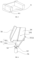
- the nozzle 43 in FIG. 4 is a state diagram when extended, and the dashed line represents the water spraying range, that is, the water sprayed from the nozzles 43 on both sides can cover the entire mirror 61.
- the concealed corner laser radar integration device provided by the present invention is mounted on the fenders 80 on both sides of a front end of a vehicle body, with a working angle forming an included angle of 30 degrees with a forward direction of the vehicle body, and can perceive a horizontal field of view of 120 degrees.
- the working principle of the concealed corner laser radar integration device is as follows: when a user has a driving need, the autonomous driving or advanced auxiliary driving domain controller sends a turning-on signal for the integrated device of corner laser radars, the controller 70 in the integrated device first drives the first motor 31 to rotate forwards.
- the lifting structure 30 starts to work, and under rotation of the transmission shaft 32, the first gear 33, and the screw rod 34, the first lifting rod 351 and the second lifting rod 352 drives the cover plate 10 to ascend and open the concealing opening.
- the controller 70 drives the second motor 51 to rotate forwards, the ejection structure 50 starts to work; under drive of the decelerator 52 and the second gear 53, the second movement rod 552 generates rotation, the first movement rod 551 drives the movement plate 54 to move, the laser radar 60 and the cleaning structure 40 are ejected to the exterior of the fender 80 and form an angle of 30 degrees with a forward direction of a vehicle body, the laser radar 60 starts to work.
- the laser radar 60 When the laser radar 60 detects that the mirror 61 is affected by dirt, it transmits a dirt signal to the autonomous driving or advanced auxiliary driving domain controller, the autonomous driving or advanced auxiliary driving domain controller sends a cleaning signal to the controller 70 in the integrated device, and the autonomous driving or advanced auxiliary driving domain controller drives a cleaning pump to pressurize a waterway; after a delay for a period of time, the controller 70 in the integrated device drives the cleaning structure 40 to work, the electromagnetic valve 42 is opened, and the nozzle 43 sprays water to clean the mirror 61 of the laser radar 60; when cleaning ends, the electromagnetic valve 42 is closed.
- the autonomous driving or advanced auxiliary driving domain controller When exiting the driving function, the autonomous driving or advanced auxiliary driving domain controller sends a turning-off signal for the integrated device of corner laser radars, the controller 70 in the integrated device drives the first motor 31 and the second motor 51 to rotate reversely, the integrated device of corner laser radars is turned off and concealed into the fender 80.
- the concealed corner laser radar integration device has the following advantages that: by adopting the concealed scheme, the laser radars can retract into the vehicle body in a standby state to avoid generating effect on an appearance design and reduce the risk of being scratched by sand and gravel; when an autonomous driving function is activated, the laser radars are rotated out and reach working positions to enhance a sence of technology.
- the concealed cleaning structure is integrated, cleanliness of the mirrors of the laser radars are always maintained during autonomous driving, the frequency of manual cleaning is greatly reduced, and users' experience is improved.
- the number of the corner laser radars is reduced from 4-5 to 2, such that a cost advantage exists.
- the arrangement is at positions on the front fender, the risk of collision is reduced compared with that of positions of front and rear bumpers.
- the present invention further provides a vehicle, which includes the above-described concealed corner laser radar integration device.
- vehicle which includes the above-described concealed corner laser radar integration device.
- Other technical features of the vehicle can refer to the prior art and are not repeated here.
Landscapes
- Engineering & Computer Science (AREA)
- Physics & Mathematics (AREA)
- Remote Sensing (AREA)
- Computer Networks & Wireless Communication (AREA)
- General Physics & Mathematics (AREA)
- Radar, Positioning & Navigation (AREA)
- Electromagnetism (AREA)
- Mechanical Engineering (AREA)
- Power Engineering (AREA)
- Life Sciences & Earth Sciences (AREA)
- Geology (AREA)
- Structural Engineering (AREA)
- Optical Radar Systems And Details Thereof (AREA)
Abstract
Description
- This patent application claims priority of
Chinese patent application filed on May 12, 2021, with an application number 202121029038.3 - The present invention relates to the technical field of laser radars, and in particular to a concealed corner laser radar integration device and a vehicle having same.
- Laser radars are important sensors for achieving high-level intelligent driving and autonomous driving. Using laser radars can compensate for the shortcomings of cameras and millimeter wave radars: compared with cameras, they can build more realistic 3D environments without relying on ambient light, and have higher resolutions and more accurate object recognition ability compared with millimeter wave radars.
- Currently, laser radars are limited by volumes of lasers and areas of laser emitting (receiving) mirrors, their overall sizes are larger than that of cameras and millimeter wave radars, making it difficult to arrange them on entire vehicles and susceptible to limitations in layout and styling.
- Horizontal view field angles (view field ranges for sensing point cloud information) of laser radars are generally around 120 degrees. In order to perceive a 360 degree horizontal field of view, the prior art usually requires 4-5 laser radars for view field splicing. Corner laser radars, as the name suggests, are generally mounted at corners, or sides, or lower positions at both sides of front and rear bumpers, of a vehicle body, to be responsible for sensing lateral field of view and serve as a supplement to the fields of view of forward and backward laser radars, thereby achieving a 360 degree horizontal field of view of laser radars.
- There are some defects in the technical solutions in the prior art.
- 1. A device that fixes a laser radar to a vehicle body is relatively simple in appearance and has a significant impact on the design, it is unable to reflect technological sense of autonomous driving usage scenarios and heat dissipation issues of the laser radar will be caused.
- 2. A horizontal view field angle of a laser radar is generally around 120 degrees, and the arrangement plan of 4-5 laser radars will cause waste of the view field angle. Moreover, laser radars are expensive, with a single cost usually greater than 5000 RMB, such an arrangement manner is not conducive to the overall cost of a vehicle.
- 3. Regarding the arrangement at lower positions of sides and corners of front and rear bumpers, these positions are collision prone areas; combined with the characteristic of the high cost of laser radars, such an arrangement manner is not conducive to the economy of maintenance for an entire vehicle.
- 4. Laser radars adopt a fixed scheme, with lenses exposed to the outside; while the laser radars' lenses are mostly made of PC or glass material, with hardnesses less than that of sand and gravel, and a higher risk of scratches during use.
- In view of this, the present invention provides a concealed corner laser radar integration device and a vehicle having same, which reduce the number of corner laser radars from 4-5 to 2, such that a cost advantage exists. The arrangement is at positions on a front fender, such that the risk of collision is reduced compared with that of the arrangement at positions of front and rear bumpers. A concealed cleaning system is integrated so as to improve users' experience; at the same time, the requirement for beauty of a roof design is met, and a sense of technology of a vehicle is enhanced.
- The present invention provides a concealed corner laser radar integration device comprises at least a cover plate, a fixed support, a lifting structure, an ejection structure, a laser radar, and a controller; wherein the cover plate is located on a fender of a vehicle body and matches an opening of the fender in terms of size; the fixed support, the lifting structure, the ejection structure, the laser radar, and the controller are all located inside the fender; the lifting structure is arranged on the fixed support and is connected to the cover plate, and can drive the cover plate to move upward and downward under control of the controller; the laser radar is arranged on the ejection structure; the ejection structure is arranged on the fixed support and can move outward relative to the fixing support under control of the controller to push the laser radar out from the inside of the fender.
- Furthermore, the fixing support comprises first fixing plates and a connection plate, the first fixing plates are located at two sides of the connection plate, and the first fixing plates are fixed to a front body longitudinal beam at an inner side of the fender through bolts.
- Furthermore, the lifting structure comprises at least a first motor, a transmission shaft, a first gear, a screw rod, a lifting rod, a sliding rail, a fixing block, and a second fixing plate; the sliding rail inclines upward and inward from a lower part of the fixing support, a bottom end thereof is fixed to the connection plate, and the fixing block is arranged at a top end thereof; the screw rod passes through the fixing block and is arranged parallel to the sliding rail, the lifting rod is arranged at a lower end thereof, the first gear is fixed at a top part of the screw rod, and the lifting rod is connected to the cover plate; the first motor and the controller are fixed on the second fixing plate, the first motor is connected to the transmission shaft, and the transmission shaft meshes with the first gear.
- Furthermore, the fixing block is connected to the screw rod by screw thread; the lifting rod comprises a first lifting rod and a second lifting rod, the first lifting rod is sleeved on and connected by screw thread to a lower end of the screw rod, and the second lifting rod has one end connected to the first lifting rod and another end fixedly connected to a bottom end of a side of the cover plate.
- Furthermore, a cleaning structure is included, and the cleaning structure is arranged on the ejection structure together with the laser radar.
- Furthermore, the cleaning structure comprises at least a fixing bracket, an electromagnetic valve, a nozzle, a connection part, and a water inlet; the electromagnetic valve has one end connected to the connection part and another end connected to the water inlet, the water inlet is connected to a pipeline which is connected to a waterway of an entire vehicle; the nozzle is connected to the connection part and has a telescoping function.
- Furthermore, the ejection structure comprises at least a second motor, a decelerator, a second gear, a movement plate, a movement rod, and a sealing strip; an output shaft of the second motor is connected to the decelerator, the decelerator is connected to the second gear; the movement plate is placed on the connection plate of the fixing support and forms a preset angle with an outside edge of the connection plate; the laser radar and the cleaning structure are mounted on the movement plate, the sealing strip is mounted at a front side of the movement plate.
- Furthermore, the movement plate is provided with a hole, the movement rod comprises a first movement rod and second movement rod, the second movement rod is connected to the first movement rod by a preset angle; a lower part of an end of the first movement rod is provided with a convex column, the convex column is clamped with the hole; the second movement rod is arc-shaped, an outside section thereof is provided with teeth, the teeth mesh with the second gear.
- Furthermore, one side of the laser radar is fixed with a mirror, and the other side is equipped with a second wire harness, the second wire harness is connected to an autonomous driving domain controller or an advanced auxiliary driving domain controller.
- The present invention further provides a vehicle, the vehicle comprises the aforementioned concealed corner laser radar integration device.
- The present invention provides a concealed corner laser radar integration device, which adopts a concealed scheme. The laser radars can retract into a vehicle body in a standby state to avoid generating effect on an appearance design and reduce the risk of being scratched by sand and gravel; when an autonomous driving function is activated, the laser radars are rotated out and reach working positions to enhance a sence of technology. The concealed cleaning structure is integrated, cleanliness of the mirrors of the laser radars are always maintained during autonomous driving, the frequency of manual cleaning is greatly reduced, and users' experience is improved. The number of the corner laser radars is reduced from 4-5 to 2, such that a cost advantage exists. The arrangement is at positions on a front fender, the risk of collision is reduced compared with that of positions of front and rear bumpers.
-
-
FIG. 1 is a schematic view of mounting positions of a concealed corner laser radar integration device of the present invention on a vehicle body. -
FIG. 2 is an overall structural schematic view of a concealed corner laser radar integration device of the present invention. -
FIG. 3 is a structural schematic view of a lifting structure in the present invention. -
FIG. 4 is a schematic view of a cleaning structure in the present invention. -
FIG. 5 is a structural schematic view of a fixing bracket in the present invention. -
FIG. 6 is a schematic view of an ejection structure in the present invention. -
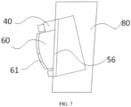
FIG. 7 is a top view of laser radars in a turning-on state in the present invention. - Specific implementations of the present invention are further described in detail below in combination with the accompany drawings and embodiments. The following embodiments are used to illustrate the present invention, but are not used to limit the scope of the present invention.
- In the description of the present invention, it should be noted that orientations or position relationships indicated in this description are based on orientations or position relationships shown in the accompanying drawings, and are only for the convenience of describing the present invention and simplifying the description, rather than indicating or implying that devices or elements referred to must have specific orientations or be constructed and operated in specific orientations, and therefore cannot be understood as any limitation to the present invention.
- Referring to
FIG. 1 and FIG. 2 , a c concealed corner laser radar integration device provided by the present invention includes at least acover plate 10, afixed support 20, alifting structure 30, acleaning structure 40, anejection structure 50, alaser radar 60, and acontroller 70. Thecover plate 10 is located on afender 80 of a vehicle body and matches an opening of thefender 80 in terms of size. Thefixed support 20, thelifting structure 30, thecleaning structure 40, theejection structure 50, thelaser radar 60, and thecontroller 70 are all located inside thefender 80. Thelifting structure 30 is arranged on thefixed support 20 and is connected to thecover plate 10, and can drive thecover plate 10 to move upward and downward under control of thecontroller 70; thelaser radar 60 is arranged on theejection structure 50; theejection structure 50 is arranged on thefixed support 20 and and can move outward relative to thefixing support 20 under control of thecontroller 70 to push thelaser radar 60 out from the inside of thefender 80. Thecleaning structure 40 is arranged on theejection structure 50 together with thelaser radar 60, thecontroller 70 is located above thelaser radar 60 and is connected to an autonomous driving domain controller or an advanced auxiliary driving domain controller through a first wire harness. - Specifically, referring to
FIG. 2 again, thefixing support 20 includesfirst fixing plates 21 and aconnection plate 22, thefirst fixing plates 21 are located at two sides of theconnection plate 22, and thefirst fixing plates 21 are fixed to a front body longitudinal beam at an inner side of thefender 80 through bolts. - Specifically, referring to
FIG. 2 andFIG. 3 , thelifting structure 30 includes at least afirst motor 31, atransmission shaft 32, afirst gear 33, ascrew rod 34, alifting rod 35, a slidingrail 36, afixing block 37, and asecond fixing plate 38. - Furthermore, the sliding
rail 36 extends inclinedly upward and inward from a lower part of thefixing support 20, a bottom end thereof is fixed to theconnection plate 22, and thefixing block 37 is arranged at a top end thereof. Thescrew rod 34 passes through thefixing block 37 and is arranged parallel to the slidingrail 36, thefixing block 37 is connected to thescrew rod 34 by screw thread, and thescrew rod 34 has a lower end being provided with thelifting rod 35 and a top end fixed with thefirst gear 33. Thelifting rod 35 includes afirst lifting rod 351 and asecond lifting rod 352, thefirst lifting rod 351 is sleeved on and connected by screw thread to the lower end of thescrew rod 34, and thesecond lifting rod 352 has one end connected to thefirst lifting rod 351 by a preset angle and another end fixedly connected to a bottom end of a side of thecover plate 10. Thefirst motor 31 and thecontroller 70 are fixed on thesecond fixing plate 38, themotor 31 is connected to thetransmission shaft 32, and thetransmission shaft 32 meshes with thefirst gear 33. When thefirst motor 31 rotates forward, it drives thetransmission shaft 32 to rotate, thetransmission shaft 32 drives thefirst gear 33 to rotate, and thefirst gear 33 drives thescrew rod 34 to rotate. Thefirst lifting rod 351 performs upward movement relative to thescrew rod 34, and drives thesecond lifting rod 352 and thecover plate 10 to perform upward movement; thecover plate 10 is opened, thelaser radar 60 and the cleaningstructure 40 are ejected out of thefender 80 under drive of theejection structure 50. When thefirst motor 31 rotates reversely, the movement process is opposite to the forward rotation, thecover plate 10 undergoes a downward motion, and thelaser radar 60 and the cleaningstructure 40 are retracted into the interior of thefender 80 under drive of theejection structure 50. - It should be noted that the lifting
structure 30 is not limited to the liftingstructure 30 described in this embodiment. Any device with the lifting function can replace the liftingstructure 30 described in this embodiment. Specific structures of lifting structures in the prior art will not be repeated in the present invention. - Specifically, referring to
FIG. 2 ,FIG. 4 , andFIG. 5 , the cleaningstructure 40 includes at least a fixingbracket 41, anelectromagnetic valve 42, anozzle 43, aconnection part 44, and awater inlet 45; thelaser radar 60 is arranged on the fixingbracket 41, and two side of the fixingbracket 41 are respectively provided with a set of combination structure 411 including anelectromagnetic valve 42, anozzle 43, aconnection part 44, and awater inlet 45. Specifically, theelectromagnetic valve 42 has one end connected to theconnection part 44 and another end connected to thewater inlet 45 to control thewater inlet 45 to be turned on and off, thewater inlet 45 is connected to a pipeline which is connected to a waterway of an entire vehicle. Thenozzle 43 is connected to theconnection part 44, and thenozzle 43 has a telescoping function. It retracts back to the interior of theconnection part 44 when not being used and extends out of theconnection part 44 by action of water pressure during use. - It should be noted that the
nozzle 43 not only can be a telescopic structure that can extend out of or retract into theconnection part 44, but also can be a fixed structure that is directly fixed to theconnection part 44 and does not move relative to theconnection part 44. In this embodiment, thenozzle 43 is in a telescopic style. - Specifically, referring to
FIG. 2 andFIG. 6 , theejection structure 50 includes at least asecond motor 51, adecelerator 52, asecond gear 53, amovement plate 54, amovement rod 55, and a sealingstrip 56. - Furthermore, the
second motor 51 is fixed in the interior of thefender 80, its output shaft is connected to thedecelerator 52, and thedecelerator 52 is connected to thesecond gear 53. Themovement plate 54 is placed on theconnection plate 22 of the fixingsupport 20 and can swing inwards and outwards relative to the fixingsupport 20. When themovement plate 54 is rotated out relative to the fixingsupport 20, themovement plate 54 forms a preset angle with an outside edge support of theconnection plate 22, in this embodiment, it is at a 30 degree angle. Thelaser radar 60 and the cleaningstructure 40 are mounted on themovement plate 54, themovement plate 54 is further provided with ahole 541. Themovement rod 55 includes afirst movement rod 551 and asecond movement rod 552, thefirst movement rod 551 passes through a slot at thefirst fixing plate 21 close thereto, and can swing relative to thefirst fixing plate 21. A lower part of an end of thefirst movement rod 551 is provided with aconvex column 5511, theconvex column 5511 is clamped with thehole 541 of themovement plate 54; thesecond movement rod 552 is arc-shaped, an outside section thereof is provided with teeth, which mesh with thesecond gear 53. Thesecond movement rod 552 is connected to thefirst movement rod 551 by a preset angle, the sealingstrip 56 can be mounted at a front side of themovement plate 54, and can also be fixed around an inner opening of thefender 80; in this embodiment, the sealingstrip 56 is mounted at the front side of themovement plate 54. When thesecond motor 51 rotates forward, under drive of thesecond motor 51 and thedecelerator 52, thesecond gear 53 rotates to drive thesecond movement rod 552 to rotate, and further drives thefirst movement rod 551 to rotate. Themovement plate 54 connected to thefirst movement rod 551, thelaser radar 60, and the cleaningstructure 40 are rotated out and ejected to the exterior of thefender 80. At this time, the sealingstrip 56 fits around the opening in thefender 80, the sealingstrip 56 has a waterproof function, which can prevent sewage from splashing into the interior of thefender 80 when the cleaningstructure 40 is working. When thesecond motor 51 rotates reversely, themovement plate 54, thelaser radar 60, and the cleaningstructure 40 are retracted into the interior of thefender 80. - It should be noted that the
ejection structure 50 is not limited to theejection structure 30 described in this embodiment. Any device with the ejection function can replace theejection structure 50 described in this embodiment. Specific structures of ejection structures in the prior art will not be repeated in the present invention. - Specifically, referring to
FIG. 4 andFIG. 7 , a working side of thelaser radar 60 is fixed with amirror 61, and the other side is connected with a second wire harness, the second wire harness is connected to an autonomous driving or advanced auxiliary driving domain controller. When thelaser radar 60 detects that themirror 61 is affected by dirt, the second wiring harness can transmit a signal to the autonomous driving or advanced auxiliary driving domain controller, the autonomous driving or advanced auxiliary driving domain controller sends a cleaning signal to theelectromagnetic valve 42. Theelectromagnetic valve 42 is opened, and thenozzle 43 sprays water onto themirror 61 to perform cleaning work. Thenozzle 43 inFIG. 4 is a state diagram when extended, and the dashed line represents the water spraying range, that is, the water sprayed from thenozzles 43 on both sides can cover theentire mirror 61. - It should be noted that, referring to
FIG. 1 andFIG. 7 , the concealed corner laser radar integration device provided by the present invention is mounted on thefenders 80 on both sides of a front end of a vehicle body, with a working angle forming an included angle of 30 degrees with a forward direction of the vehicle body, and can perceive a horizontal field of view of 120 degrees. - The working principle of the concealed corner laser radar integration device provided by the present invention is as follows: when a user has a driving need, the autonomous driving or advanced auxiliary driving domain controller sends a turning-on signal for the integrated device of corner laser radars, the
controller 70 in the integrated device first drives thefirst motor 31 to rotate forwards. The liftingstructure 30 starts to work, and under rotation of thetransmission shaft 32, thefirst gear 33, and thescrew rod 34, thefirst lifting rod 351 and thesecond lifting rod 352 drives thecover plate 10 to ascend and open the concealing opening. Afterwards, thecontroller 70 drives thesecond motor 51 to rotate forwards, theejection structure 50 starts to work; under drive of thedecelerator 52 and thesecond gear 53, thesecond movement rod 552 generates rotation, thefirst movement rod 551 drives themovement plate 54 to move, thelaser radar 60 and the cleaningstructure 40 are ejected to the exterior of thefender 80 and form an angle of 30 degrees with a forward direction of a vehicle body, thelaser radar 60 starts to work. When thelaser radar 60 detects that themirror 61 is affected by dirt, it transmits a dirt signal to the autonomous driving or advanced auxiliary driving domain controller, the autonomous driving or advanced auxiliary driving domain controller sends a cleaning signal to thecontroller 70 in the integrated device, and the autonomous driving or advanced auxiliary driving domain controller drives a cleaning pump to pressurize a waterway; after a delay for a period of time, thecontroller 70 in the integrated device drives the cleaningstructure 40 to work, theelectromagnetic valve 42 is opened, and thenozzle 43 sprays water to clean themirror 61 of thelaser radar 60; when cleaning ends, theelectromagnetic valve 42 is closed. When exiting the driving function, the autonomous driving or advanced auxiliary driving domain controller sends a turning-off signal for the integrated device of corner laser radars, thecontroller 70 in the integrated device drives thefirst motor 31 and thesecond motor 51 to rotate reversely, the integrated device of corner laser radars is turned off and concealed into thefender 80. - From the above description, it can be known that the concealed corner laser radar integration device provided by the present invention has the following advantages that: by adopting the concealed scheme, the laser radars can retract into the vehicle body in a standby state to avoid generating effect on an appearance design and reduce the risk of being scratched by sand and gravel; when an autonomous driving function is activated, the laser radars are rotated out and reach working positions to enhance a sence of technology. The concealed cleaning structure is integrated, cleanliness of the mirrors of the laser radars are always maintained during autonomous driving, the frequency of manual cleaning is greatly reduced, and users' experience is improved. The number of the corner laser radars is reduced from 4-5 to 2, such that a cost advantage exists. The arrangement is at positions on the front fender, the risk of collision is reduced compared with that of positions of front and rear bumpers.
- The present invention further provides a vehicle, which includes the above-described concealed corner laser radar integration device. Other technical features of the vehicle can refer to the prior art and are not repeated here.
- The above described are only specific implementations of the present invention, however, the protection scope of the present invention is not limited here. Any change or replacement that can be easily thought by technical personnel familiar with the technical field within the techinical field disclosed by the present invention should be covered by the protection scope of the present invention. Therefore, the protection scope of the present invention should be based on the protection scope of the claims.
Claims (10)
- A concealed corner laser radar integration device comprising at least a cover plate (10), a fixed support (20), a lifting structure (30), an ejection structure (50), a laser radar (60), and a controller (70); wherein the cover plate (10) is located on a fender (80) of a vehicle body and matches an opening of the fender (80) in terms of size; the fixed support (20), the lifting structure (30), the ejection structure (50), the laser radar (60), and the controller (70) are all located inside the fender (80); the lifting structure (30) is arranged on the fixed support (20) and is connected to the cover plate (10), and can drive the cover plate (10) to move upward and downward under control of the controller (70); the laser radar (60) is arranged on the ejection structure (50); the ejection structure (50) is arranged on the fixed support (20) and can move outward relative to the fixing support (20) under control of the controller (70) to push the laser radar (60) out from the inside of the fender (80).
- The concealed corner laser radar integration device according to claim 1, wherein the fixing support (20) comprises first fixing plates (21) and a connection plate (22), the first fixing plates (21) are located at two sides of the connection plate (22), and the first fixing plates (21) are fixed to a front body longitudinal beam at an inner side of the fender (80) through bolts.
- The concealed corner laser radar integration device according to claim 2, wherein the lifting structure (30) comprises at least a first motor (31), a transmission shaft (32), a first gear (33), a screw rod (34), a lifting rod (35), a sliding rail (36), a fixing block (37), and a second fixing plate (38); the sliding rail (36) inclines upward and inward from a lower part of the fixing support (20), a bottom end thereof is fixed to the connection plate (22), and the fixing block (27) is arranged at a top end thereof; the screw rod (34) passes through the fixing block (37) and is arranged parallel to the sliding rail (36), the lifting rod (35) is arranged at a lower end thereof, the first gear (33) is fixed at a top part of the screw rod (34), and the lifting rod (35) is connected to the cover plate (10); the first motor (31) and the controller (70) are fixed on the second fixing plate (38), the first motor (31) is connected to the transmission shaft (32), and the transmission shaft (32) meshes with the first gear (33).
- The concealed corner laser radar integration device according to claim 3, wherein the fixing block (37) is connected to the screw rod (34) by screw thread; the lifting rod (35) comprises a first lifting rod (351) and a second lifting rod (352), the first lifting rod (351) is sleeved on and connected by screw thread to a lower end of the screw rod (34), and the second lifting rod (352) has one end connected to the first lifting rod (351) and another end fixedly connected to a bottom end of a side of the cover plate (10).
- The concealed corner laser radar integration device according to claim 1, further comprising a cleaning structure (40), wherein the cleaning structure (40) is arranged on the ejection structure (50) together with the laser radar (60).
- The concealed corner laser radar integration device according to claim 5, wherein the cleaning structure (40) comprises at least a fixing bracket (41), an electromagnetic valve (42), a nozzle (43), a connection part (44), and a water inlet (45); the electromagnetic valve (42) has one end connected to the connection part (44) and another end connected to the water inlet (45), the water inlet (45) is connected to a pipeline which is connected to a waterway of an entire vehicle; the nozzle (43) is connected to the connection part (44) and has a telescoping function.
- The concealed corner laser radar integration device according to claim 2, wherein the ejection structure (50) comprises at least a second motor (51), a decelerator (52), a second gear (53), a movement plate (54), a movement rod (55), and a sealing strip (56); an output shaft of the second motor (51) is connected to the decelerator (52), the decelerator (52) is connected to the second gear (53); the movement plate (54) is placed on the connection plate (22) of the fixing support (20) and forms a preset angle with an outside edge of the connection plate (22); the laser radar (60) and the cleaning structure (40) are mounted on the movement plate (54), the sealing strip (56) is mounted at a front side of the movement plate (54).
- The concealed corner laser radar integration device according to claim 7, wherein the movement plate (54) is provided with a hole (541), the movement rod (55) comprises a first movement rod (551) and second movement rod (552), the second movement rod (552) is connected to the first movement rod (551) by a preset angle; a lower part of an end of the first movement rod (551) is provided with a convex column (5511), the convex column (5511) is clamped with the hole (541); the second movement rod (552) is arc-shaped, an outside section thereof is provided with teeth, the teeth mesh with the second gear (53).
- The concealed corner laser radar integration device according to claim 1, wherein one side of the laser radar (60) is fixed with a mirror (61), and the other side is equipped with a second wire harness, the second wire harness is connected to an autonomous driving domain controller or an advanced auxiliary driving domain controller.
- A vehicle comprising the concealed corner laser radar integration device according to any one of claims 1-9.
Applications Claiming Priority (2)
| Application Number | Priority Date | Filing Date | Title |
|---|---|---|---|
| CN202121029038.3U CN216052167U (en) | 2021-05-12 | 2021-05-12 | Hidden angle laser radar integrated device and have its vehicle |
| PCT/CN2022/082890 WO2022237342A1 (en) | 2021-05-12 | 2022-03-24 | Concealed integrated device of corner laser radars, and vehicle having same |
Publications (2)
| Publication Number | Publication Date |
|---|---|
| EP4339636A1 true EP4339636A1 (en) | 2024-03-20 |
| EP4339636A4 EP4339636A4 (en) | 2025-04-30 |
Family
ID=80614248
Family Applications (1)
| Application Number | Title | Priority Date | Filing Date |
|---|---|---|---|
| EP22806312.9A Pending EP4339636A4 (en) | 2021-05-12 | 2022-03-24 | Hidden integrated device of corner laser radars and vehicle therewith |
Country Status (5)
| Country | Link |
|---|---|
| US (1) | US20240201335A1 (en) |
| EP (1) | EP4339636A4 (en) |
| KR (1) | KR20230165302A (en) |
| CN (1) | CN216052167U (en) |
| WO (1) | WO2022237342A1 (en) |
Families Citing this family (5)
| Publication number | Priority date | Publication date | Assignee | Title |
|---|---|---|---|---|
| CN216052167U (en) * | 2021-05-12 | 2022-03-15 | 武汉路特斯汽车有限公司 | Hidden angle laser radar integrated device and have its vehicle |
| WO2022237847A1 (en) * | 2021-05-12 | 2022-11-17 | 武汉路特斯汽车有限公司 | Laser radar integrated device and vehicle provided with same |
| CN116923267B (en) * | 2022-03-31 | 2025-06-10 | 经纬恒润(天津)研究开发有限公司 | A sensor component |
| CN217506110U (en) * | 2022-03-31 | 2022-09-27 | 经纬恒润(天津)研究开发有限公司 | Radar belt cleaning device and radar system |
| CN117284211B (en) * | 2022-06-17 | 2026-03-27 | 宁波路特斯机器人有限公司 | A method, apparatus, device, and storage medium for controlling vehicle-mounted equipment. |
Family Cites Families (8)
| Publication number | Priority date | Publication date | Assignee | Title |
|---|---|---|---|---|
| EP2003471A1 (en) * | 2007-06-11 | 2008-12-17 | IBEO Automobile Sensor GmbH | Retractable radar device |
| CN209879739U (en) * | 2019-04-27 | 2019-12-31 | 苏州易通交通科技有限公司 | Multi-angle rotating's intelligent transportation speed measuring equipment |
| CN210894691U (en) * | 2019-08-14 | 2020-06-30 | 广东机电职业技术学院 | Scanning support for planar laser radar |
| CN112477768A (en) * | 2019-09-12 | 2021-03-12 | 郑州宇通客车股份有限公司 | Laser radar mounting structure and vehicle |
| KR102670861B1 (en) * | 2019-10-25 | 2024-06-04 | 현대모비스 주식회사 | Sensor-cluster apparatus |
| CN111409739A (en) * | 2020-04-13 | 2020-07-14 | 新石器慧通(北京)科技有限公司 | Unmanned vehicle comprising laser radar with telescopic mounting structure |
| CN212473304U (en) * | 2020-04-17 | 2021-02-05 | 扬州邮动智能科技有限公司 | Laser radar with protection device for automatic driving automobile |
| CN216052167U (en) * | 2021-05-12 | 2022-03-15 | 武汉路特斯汽车有限公司 | Hidden angle laser radar integrated device and have its vehicle |
-
2021
- 2021-05-12 CN CN202121029038.3U patent/CN216052167U/en active Active
-
2022
- 2022-03-24 WO PCT/CN2022/082890 patent/WO2022237342A1/en not_active Ceased
- 2022-03-24 US US18/554,469 patent/US20240201335A1/en active Pending
- 2022-03-24 KR KR1020237037555A patent/KR20230165302A/en active Pending
- 2022-03-24 EP EP22806312.9A patent/EP4339636A4/en active Pending
Also Published As
| Publication number | Publication date |
|---|---|
| CN216052167U (en) | 2022-03-15 |
| US20240201335A1 (en) | 2024-06-20 |
| EP4339636A4 (en) | 2025-04-30 |
| KR20230165302A (en) | 2023-12-05 |
| WO2022237342A1 (en) | 2022-11-17 |
Similar Documents
| Publication | Publication Date | Title |
|---|---|---|
| EP4339636A1 (en) | Concealed integrated device of corner laser radars, and vehicle having same | |
| KR102661601B1 (en) | Mobile image recording devices and vehicles provided with such devices | |
| CN215474853U (en) | Hidden top laser radar integrated box and have its vehicle | |
| US10183653B2 (en) | On-board vehicle vision and cleaning system | |
| JP2009173246A (en) | Vehicle front side visual recognition device | |
| US20240077575A1 (en) | Laser radar integrated device and vehicle provided with same | |
| CN103287340A (en) | Automobile A-pillar optic invisible device | |
| CN201619520U (en) | External vehicle rearview mirror with auxiliary view mirror | |
| CN115593360A (en) | Roof module for forming a vehicle roof comprising an adjustable cleaning nozzle | |
| CA2364118A1 (en) | Mirror head assembly | |
| CN115320505A (en) | Hidden electronic exterior rearview mirror, vehicle and control method thereof | |
| CN218383651U (en) | Automobile-used water smoke projecting apparatus and vehicle | |
| RU2002110995A (en) | Safe car | |
| CN208915120U (en) | A kind of anticollision device, collision-prevention device and automobile for automobile | |
| DE19931014A1 (en) | Distance sensor for road vehicle covers at least complete side area of vehicle and is formed as laser scanner arranged in mirror joint of outer mirror | |
| US20030107826A1 (en) | Mirror system for improving a motorist's field of vision | |
| CN216101618U (en) | Environment-friendly solar charging pile for new energy automobile | |
| CN114179721A (en) | Safety warning device for carrying out light warning on dead zone of truck | |
| CN218877069U (en) | Novel vehicle-mounted electronic rearview mirror | |
| CN115840331B (en) | Automotive intelligent display devices, automobiles, and control methods for automotive intelligent displays | |
| CN222202403U (en) | Rearview mirror and vehicle | |
| CN117533242A (en) | Environment perception subassembly and car | |
| CN219406397U (en) | Cleaning mechanism of vehicle detection equipment and vehicle | |
| CN221650610U (en) | High-transmittance optical glass for automotive lidar | |
| CN214194218U (en) | Municipal works bend mirror structure |
Legal Events
| Date | Code | Title | Description |
|---|---|---|---|
| STAA | Information on the status of an ep patent application or granted ep patent |
Free format text: STATUS: THE INTERNATIONAL PUBLICATION HAS BEEN MADE |
|
| PUAI | Public reference made under article 153(3) epc to a published international application that has entered the european phase |
Free format text: ORIGINAL CODE: 0009012 |
|
| STAA | Information on the status of an ep patent application or granted ep patent |
Free format text: STATUS: REQUEST FOR EXAMINATION WAS MADE |
|
| 17P | Request for examination filed |
Effective date: 20230912 |
|
| AK | Designated contracting states |
Kind code of ref document: A1 Designated state(s): AL AT BE BG CH CY CZ DE DK EE ES FI FR GB GR HR HU IE IS IT LI LT LU LV MC MK MT NL NO PL PT RO RS SE SI SK SM TR |
|
| DAV | Request for validation of the european patent (deleted) | ||
| DAX | Request for extension of the european patent (deleted) | ||
| A4 | Supplementary search report drawn up and despatched |
Effective date: 20250328 |
|
| RIC1 | Information provided on ipc code assigned before grant |
Ipc: G01S 7/497 20060101ALI20250324BHEP Ipc: G01S 17/931 20200101ALI20250324BHEP Ipc: B60R 11/04 20060101ALI20250324BHEP Ipc: B60R 11/00 20060101ALI20250324BHEP Ipc: G01S 7/481 20060101AFI20250324BHEP |