EP4339620A1 - Sensor and electronic device - Google Patents
Sensor and electronic device Download PDFInfo
- Publication number
- EP4339620A1 EP4339620A1 EP23157015.1A EP23157015A EP4339620A1 EP 4339620 A1 EP4339620 A1 EP 4339620A1 EP 23157015 A EP23157015 A EP 23157015A EP 4339620 A1 EP4339620 A1 EP 4339620A1
- Authority
- EP
- European Patent Office
- Prior art keywords
- support structure
- support
- electrode
- counter
- movable region
- Prior art date
- Legal status (The legal status is an assumption and is not a legal conclusion. Google has not performed a legal analysis and makes no representation as to the accuracy of the status listed.)
- Granted
Links
Images



Classifications
-
- G—PHYSICS
- G01—MEASURING; TESTING
- G01P—MEASURING LINEAR OR ANGULAR SPEED, ACCELERATION, DECELERATION, OR SHOCK; INDICATING PRESENCE, ABSENCE, OR DIRECTION, OF MOVEMENT
- G01P15/00—Measuring acceleration; Measuring deceleration; Measuring shock, i.e. sudden change of acceleration
- G01P15/02—Measuring acceleration; Measuring deceleration; Measuring shock, i.e. sudden change of acceleration by making use of inertia forces using solid seismic masses
- G01P15/08—Measuring acceleration; Measuring deceleration; Measuring shock, i.e. sudden change of acceleration by making use of inertia forces using solid seismic masses with conversion into electric or magnetic values
- G01P15/097—Measuring acceleration; Measuring deceleration; Measuring shock, i.e. sudden change of acceleration by making use of inertia forces using solid seismic masses with conversion into electric or magnetic values by vibratory elements
-
- G—PHYSICS
- G01—MEASURING; TESTING
- G01P—MEASURING LINEAR OR ANGULAR SPEED, ACCELERATION, DECELERATION, OR SHOCK; INDICATING PRESENCE, ABSENCE, OR DIRECTION, OF MOVEMENT
- G01P15/00—Measuring acceleration; Measuring deceleration; Measuring shock, i.e. sudden change of acceleration
- G01P15/02—Measuring acceleration; Measuring deceleration; Measuring shock, i.e. sudden change of acceleration by making use of inertia forces using solid seismic masses
- G01P15/08—Measuring acceleration; Measuring deceleration; Measuring shock, i.e. sudden change of acceleration by making use of inertia forces using solid seismic masses with conversion into electric or magnetic values
-
- G—PHYSICS
- G01—MEASURING; TESTING
- G01P—MEASURING LINEAR OR ANGULAR SPEED, ACCELERATION, DECELERATION, OR SHOCK; INDICATING PRESENCE, ABSENCE, OR DIRECTION, OF MOVEMENT
- G01P15/00—Measuring acceleration; Measuring deceleration; Measuring shock, i.e. sudden change of acceleration
- G01P15/02—Measuring acceleration; Measuring deceleration; Measuring shock, i.e. sudden change of acceleration by making use of inertia forces using solid seismic masses
- G01P15/08—Measuring acceleration; Measuring deceleration; Measuring shock, i.e. sudden change of acceleration by making use of inertia forces using solid seismic masses with conversion into electric or magnetic values
- G01P15/0802—Details
-
- G—PHYSICS
- G01—MEASURING; TESTING
- G01P—MEASURING LINEAR OR ANGULAR SPEED, ACCELERATION, DECELERATION, OR SHOCK; INDICATING PRESENCE, ABSENCE, OR DIRECTION, OF MOVEMENT
- G01P15/00—Measuring acceleration; Measuring deceleration; Measuring shock, i.e. sudden change of acceleration
- G01P15/18—Measuring acceleration; Measuring deceleration; Measuring shock, i.e. sudden change of acceleration in two or more dimensions
-
- G—PHYSICS
- G01—MEASURING; TESTING
- G01P—MEASURING LINEAR OR ANGULAR SPEED, ACCELERATION, DECELERATION, OR SHOCK; INDICATING PRESENCE, ABSENCE, OR DIRECTION, OF MOVEMENT
- G01P15/00—Measuring acceleration; Measuring deceleration; Measuring shock, i.e. sudden change of acceleration
- G01P15/02—Measuring acceleration; Measuring deceleration; Measuring shock, i.e. sudden change of acceleration by making use of inertia forces using solid seismic masses
- G01P15/08—Measuring acceleration; Measuring deceleration; Measuring shock, i.e. sudden change of acceleration by making use of inertia forces using solid seismic masses with conversion into electric or magnetic values
- G01P2015/0805—Measuring acceleration; Measuring deceleration; Measuring shock, i.e. sudden change of acceleration by making use of inertia forces using solid seismic masses with conversion into electric or magnetic values being provided with a particular type of spring-mass-system for defining the displacement of a seismic mass due to an external acceleration
- G01P2015/0808—Measuring acceleration; Measuring deceleration; Measuring shock, i.e. sudden change of acceleration by making use of inertia forces using solid seismic masses with conversion into electric or magnetic values being provided with a particular type of spring-mass-system for defining the displacement of a seismic mass due to an external acceleration for defining in-plane movement of the mass, i.e. movement of the mass in the plane of the substrate
- G01P2015/0811—Measuring acceleration; Measuring deceleration; Measuring shock, i.e. sudden change of acceleration by making use of inertia forces using solid seismic masses with conversion into electric or magnetic values being provided with a particular type of spring-mass-system for defining the displacement of a seismic mass due to an external acceleration for defining in-plane movement of the mass, i.e. movement of the mass in the plane of the substrate for one single degree of freedom of movement of the mass
- G01P2015/0814—Measuring acceleration; Measuring deceleration; Measuring shock, i.e. sudden change of acceleration by making use of inertia forces using solid seismic masses with conversion into electric or magnetic values being provided with a particular type of spring-mass-system for defining the displacement of a seismic mass due to an external acceleration for defining in-plane movement of the mass, i.e. movement of the mass in the plane of the substrate for one single degree of freedom of movement of the mass for translational movement of the mass, e.g. shuttle type
Definitions
- Embodiments described herein relate generally to a sensor and an electronic device.
- a sensor includes a base body, a support portion fixed to the base body, and a first member supported by the support portion.
- a gap is provided between the base body and a part of the first member.
- the first member includes a supported region, a first movable region, a first structure, a first support structure, a first connection structure, a first connect portion, and a first beam.
- the support portion is located between the base body and the supported region in a first direction from the base body to the support portion.
- the first beam extends along a second direction crossing the first direction.
- a first beam position of the first beam in the second direction is located between a first movable region position of the first movable region in the second direction and a support portion position of the support portion in the second direction.
- a first end of the first beam is connected to the first connecting structure.
- a first other end of the first beam is connected to the supported region.
- a first structure position of the first structure in the second direction is located between the first movable region position and the first beam position.
- a first connection structure position of the first connection structure in the second direction is located between the first structure position and the first beam position.
- a first support structure position of the first support structure in the second direction is located between the first structure position and the support portion position.
- the first structure includes a first portion, a first other portion, and a first intermediate portion.
- a third direction from the first portion to the first other portion crosses a plane including the first direction and the second direction.
- the first intermediate portion is between the first portion and the first other portion.
- the first portion is connected to the first connection structure.
- the first other portion is connected to the first movable region.
- the first intermediate portion is connected to the first support structure.
- the first connect portion connects the first connection structure to the first support structure.
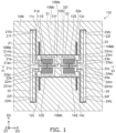
- FIG. 1 is a schematic plan view illustrating a sensor according to the first embodiment.
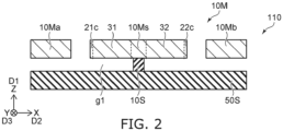
- FIG. 2 is a schematic cross-sectional view illustrating the sensor according to the first embodiment.
- FIG. 2 is a cross-sectional view taken along the line A1-A2 of FIG. 1 .
- a sensor 110 includes a base body 50S, a support portion 10S and a first member 10M.
- the support portion 10S is fixed to the base body 50S.
- the first member 10M is supported by the support portion 10S.
- a gap g1 is provided between the base body 50S and a part of the first member 10M. At least a part of the first member 10M may be conductive.
- a first direction D1 from the base body 50S to the support portion 10S is defined as a Z-axis direction.
- One direction perpendicular to the Z-axis direction is defined as an X-axis direction.
- the direction perpendicular to the Z-axis direction and the X-axis direction is defined as a Y-axis direction.
- the first member 10M includes a supported region 10Ms, a first movable region 10Ma, a first structure 21, a first support structure 11S, a first connection structure 21c, a first connect portion 11c and a first beam 31.
- the support portion 10S is provided between the base body 50S and the supported region 10Ms in the first direction D1.
- the first beam 31 extends along a second direction D2.
- the second direction D2 crosses the first direction D1.
- the second direction D2 is, for example, the X-axis direction.
- a first beam position of the first beam 31 in the second direction D2 is located between a first movable region position of the first movable region 10Ma in the second direction D2 and a support portion position of the support portion 10S in the second direction D2.
- a first end 31e of the first beam 31 is connected to the first connection structure 21c.
- a first other end 31f of the first beam 31 is connected to the supported region 10Ms.
- a first structure position of the first structure 21 in the second direction D2 is located between the first movable region position (the position of the first movable region 10Ma in the second direction D2) and the first beam position (the position of the first beam 31 in the second direction D2).
- a first connection structure position of the first connection structure 21c in the second direction D2 is located between the first structure position and the first beam position.
- a first support structure position of the first support structure 11S in the second direction D2 is located between the first structure position and the support portion position.
- the first structure 21 includes a first portion 21e, a first other portion 21f, and a first intermediate portion 21m.
- the first intermediate portion 21m is located between the first portion 21e and the first other portion 21f.
- the first portion 21e is connected to the first connection structure 21c.
- the first other portion 21f is connected to the first movable region 10Ma.
- the first intermediate portion 21m is connected to the first support structure 11S.
- the first member 10M includes a first portion connect portion 21ec, a first other portion connect portion 21fc, and a first intermediate portion connect portion 21mc.
- the first portion connect portion 21ec connects the first portion 21e to the first connection structure 21c.
- the first other portion connect portion 21fc connects the first other portion 21f to the first movable region 10Ma.
- the first intermediate portion connect portion 21mc connects the first intermediate portion 21m to the first support structure 11S.
- the first connect portion 11c connects the first connection structure 21c to the first support structure 11S.
- the first member 10M can move along the X-axis direction.
- the first movable region 10Ma moves along the X-axis direction.
- the movement of the first movable region 10Ma is transmitted to the first connection structure 21c by the first structure 21.
- the first structure 21 is, for example, a lever.
- the first portion 21e is, for example, a point of action.
- the first other portion 21f is, for example, a point of force.
- the first intermediate portion 21m is, for example, a fulcrum.
- the first connection structure 21c For example, stress along the X-axis direction is applied to the first connection structure 21c. As a result, compressive stress or tensile stress is applied to the first beam 31. As described later, when an AC signal is applied, the first beam 31 vibrates. The resonance frequency of the first beam 31 changes according to the stress applied to the first beam 31. By detecting a change in the resonance frequency of the first beam 31, it is possible to detect an externally applied force (e.g., acceleration).
- an externally applied force e.g., acceleration
- the first connection structure 21c is connected to the first support structure 11S by the first connect portion 11c.
- the movement of the first connection structure 21c is stabilized as compared with a reference example in which the first connection structure 21c is not connected to the first support structure 11S.
- stable detection can be achieved as compared with the reference example.
- a sensor that can improve detection accuracy can be provided.
- the first member 10M includes a second structure 22, a second support structure 12S, and a second connect portion 12c.
- a second structure position of the second structure 22 in the second direction D2 is located between the first movable region position and the first beam position.
- a second support structure position of the second support structure 12S in the second direction D2 is located between the second structure position and the support portion position.
- the second structure 22 includes a second portion 22e, a second other portion 22f, and a second intermediate portion 22m.
- a direction from the second other portion 22f to the second portion 22e is along the third direction D3.
- the second intermediate portion 22m is located between the second other portion 22f and the second portion 22e.
- the second portion 22e is connected to the first connection structure 21c.
- the second other portion 22f is connected to the first movable region 10Ma.
- the second intermediate portion 22m is connected to the second support structure 12S.
- the first member 10M includes a second portion connect portion 22ec, a second other portion connect portion 22fc, and a second intermediate portion connect portion 22mc.
- the second portion connect portion 22ec connects the second portion 22e to the first connection structure 21c.
- the second other portion connect portion 22fc connects the second other portion 22f to the first movable region 10Ma.
- the second intermediate portion connect portion 22mc connects the second intermediate portion 22m to the second support structure 12S.
- the second connect portion 12c connects the first connection structure 21c to the second support structure 12S.
- the first connection structure 21c becomes stable.
- the first connection structure 21c is located between at least a part of the second support structure 12S and at least a part of the first support structure 11S.
- the first connect portion 11c is located between the first connection structure 21c and at least a part of the first support structure 11S.
- the second connect portion 12c is located between at least a part of the second support structure 12S and the first connection structure 21c.
- the second structure 22 is, for example, a lever.
- the second portion 22e is, for example, a point of action.
- the second other portion 22f is, for example, a point of force.
- the second intermediate portion 22m is, for example, a fulcrum.
- the first connection structure 21c is stabilized. More stable detection becomes possible.
- the first member 10M includes a second movable region 10Mb, a third structure 23, a third support structure 13S, a second connection structure 22c, a third connect portion 13c, and a second beam 32.
- the supported region 10Ms is located between the first movable region 10Ma and the second movable region 10Mb.
- the second beam 32 extends along the second direction D2.
- a second beam position of the second beam 32 in the second direction D2 is located between the support portion position and a second movable region position of the second movable region 10Mb in the second direction D2.
- a second end 32e of the second beam 32 is connected to the second connection structure 22c.
- a second other end 32f of the second beam 32 is connected to the supported region 10Ms.
- a third structure position of the third structure 23 in the second direction D2 is located between the second beam position and the second movable region position.
- a second connection structure position of the second connection structure 22c in the second direction D2 is located between the second beam position and the third structure position.
- a third support structure position of the third support structure 13S in the second direction D2 is located between the support portion position and the third structure position.
- the third structure 23 includes a third portion 23e, a third other portion 23f, and a third intermediate portion 23m.
- a direction from the third portion 23e to the third other portion 23f is along the third direction D3.
- the third intermediate portion 23m is located between the third portion 23e and the third other portion 23f.
- the third portion 23e is connected to the second connection structure 22c.
- the third other portion 23f is connected to the second movable region 10Mb.
- the third intermediate portion 23m is connected to the third support structure 13S.
- the first member 10M includes a third portion connect portion 23ec, a third other portion connect portion 23fc, and a third intermediate portion connect portion 23mc.
- the third portion connect portion 23ec connects the third portion 23e to the second connection structure 22c.
- the third other portion connect portion 23fc connects the third other portion 23f to the second movable region 10Mb.
- the third intermediate portion connect portion 23mc connects the third intermediate portion 23m to the third support structure 13S.
- the third connect portion 13c connects the second connection structure 22c to the third support structure 13S.
- the second connection structure 22c is stabilized.
- the third structure 23 is, for example, a lever.
- the third portion 23e is, for example, a point of action.
- the third other portion 23f is, for example, a point of force.
- the third intermediate portion 23m is, for example, a fulcrum.
- the first member 10M includes a fourth structure 24, a fourth support structure 14S, and a fourth connect portion 14c.
- a fourth structure position the fourth structure 24 in the second direction D2 is located between the second beam position and the second movable region position.
- a fourth support structure position of the fourth support structure 14S in the second direction D2 is located between the support portion position and the fourth structure position.
- the fourth structure 24 includes a fourth portion 24e, a fourth other portion 24f, and a fourth intermediate portion 24m.
- a direction from the fourth other portion 24f to the fourth portion 24e is along the third direction D3.
- the fourth intermediate portion 24m is located between the fourth other portion 24f and the fourth portion 24e.
- the fourth portion 24e is connected to the second connection structure 22c.
- the fourth other portion 24f is connected to the second movable region 10Mb.
- the fourth intermediate portion 24m is connected to the fourth support structure 14S.
- the first member 10M includes a fourth portion connect portion 24ec, a fourth other portion connect portion 24fc, and a fourth intermediate portion connect portion 24mc.
- the fourth portion connect portion 24ec connects the fourth portion 24e to the second connection structure 22c.
- the fourth other portion connect portion 24fc connects the fourth other portion 24f to the second movable region 10Mb.
- the fourth intermediate portion connect portion 24mc connects the fourth intermediate portion 24m to the fourth support structure 14S.
- the fourth connect portion 14c connects the second connection structure 22c to the fourth support structure 14S.
- the second connection structure 22c is stabilized.
- the second connection structure 22c is located between at least a part of the fourth support structure 14S and at least a part of the third support structure 13S.
- the third connect portion 13c is located between the second connection structure 22c and at least a part of the third support structure 13S.
- the fourth connect portion 14c is located between at least a part of the fourth support structure 14S and the second connection structure 22c.
- the fourth structure 24 is, for example, a lever.
- the fourth portion 24e is, for example, a point of action.
- the fourth other portion 24f is, for example, a point of force.
- the fourth intermediate portion 24m is, for example, a fulcrum.
- FIG. 3 is a schematic plan view illustrating a part of the sensor according to the first embodiment.
- FIG. 3 a portion of FIG. 1 is shown enlarged.
- the sensor 110 may include a first electrode 51 and a first counter electrode 51A.
- the first electrode 51 is fixed to the base body 50S.
- the first counter electrode 51A is fixed to the base body 50S.
- the first member 10M further includes a first beam electrode 31E connected to the first beam 31 and a first counter beam electrode 31AE connected to the first beam 31.
- the first beam 31 is located between the first counter beam electrode 31AE and the first beam electrode 31E.
- the first electrode 51 faces the first beam electrode 31E.
- the first counter electrode 51A faces the first counter beam electrode 31AE.
- the controller 70 may be provided.
- the controller 70 may be included in the sensor 110.
- the controller 70 may be provided separately from the sensor 110.
- the controller 70 is electrically connected to the first electrode 51, the first counter electrode 51A, the first beam electrode 31E, and the first counter beam electrode 31AE.
- the first beam electrode 31E and the first counter beam electrode 31AE are electrically connected to the first member 10M (for example, the supported region 10Ms).
- the controller 70 is configured to apply a driving signal including an AC component between the first electrode 51 and the first beam electrode 31E.
- the controller 70 is configured to detect an electric signal generated between the first counter electrode 51A and the first counter beam electrode 31AE. By detecting a change in the electric signal generated between the first counter electrode 51A and the first counter beam electrode 31AE, an external force can be detected.
- the sensor 110 may include a second electrode 52 and a second counter electrode 52A.
- the second electrode 52 is fixed to the base body 50S.
- the second counter electrode 52A is fixed to the base body 50S.
- the first member 10M may further include a second beam electrode 32E connected to the second beam 32 and a second counter beam electrode 32AE connected to the second beam 32.
- the second beam 32 is located between the second counter beam electrode 32AE and the second beam electrode 32E.
- the second electrode 52 faces the second beam electrode 32E.
- the second counter electrode 52A faces the second counter beam electrode 32AE.
- the second beam electrode 32E and the second counter beam electrode 32AE are electrically connected to the first member 10M (for example, the supported region 10Ms).
- the controller 70 is configured to apply the drive signal including an AC component between the second electrode 52 and the second beam electrode 32E.
- the controller 70 is configured to detect an electric signal generated between the second counter electrode 52A and the second counter beam electrode 32AE.
- the first member 10M may include a third movable region 10Mc and a fourth movable region 10Md.
- a direction from the fourth movable region 10Md to the third movable region 10Mc is along the third direction D3.
- the third movable region 10Mc and the fourth movable region 10Md are continuous with the first movable region 10Ma and the second movable region 10Mb.
- the supported region 10Ms is provided between the third movable region 10Mc and the fourth movable region 10Md.
- the first member 10M may further include a first movable region connect portion 11A.
- a position of the first support structure 11S in the third direction D3 is located between a position of the supported region 10Ms in the third direction D3 and a position of the third movable region 10Mc in the third direction D3.
- the first movable region connect portion 11A connects the first support structure 11S to the third movable region 10Mc.
- the first member 10M may further include a second movable region connect portion 12A.
- a position of the second support structure 12S in the third direction D3 is located between a position of the fourth movable region 10Md in the third direction D3 and the position of the supported region 10Ms in the third direction D3.
- the second movable region connect portion 12A connects the second support structure 12S to the fourth movable region 10Md.
- the first member 10M may further include a third movable region connect portion 13A.
- a position of the third support structure 13S in the third direction D3 is located between the position of the supported region 10Ms in the third direction D3 and the position of the third movable region 10Mc in the third direction D3.
- the third movable region connect portion 13A connects the third support structure 13S to the third movable region 10Mc.
- the first member 10M may further include a fourth movable region connect portion 14A.
- a position of the fourth support structure 14S in the third direction D3 is located between the position of the fourth movable region 10Md in the third direction D3 and the position of the supported region 10Ms in the third direction D3.
- the fourth movable region connect portion 14A connects the fourth support structure 14S to the fourth movable region 10Md.
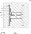
- FIG. 4 is a schematic plan view illustrating the sensor according to the first embodiment.
- FIG. 4 a portion of FIG. 1 is shown enlarged.
- a length of the first connect portion 11c along the third direction D3 is defined as a first length L1.
- a length of the first connect portion 11c along the second direction D2 is defined as a second length L2.
- the first length L1 is longer than the second length L2.
- the first connection structure 21c connected to the first connect portion 11c can be easily displaced along the second direction D2. The position of the first connection structure 21c in the third direction D3 becomes stable.
- a distance between the first portion 21e and the first intermediate portion 21m along the third direction D3 is defined as a first distance d1.
- a distance between the first intermediate portion 21m and the first other portion 21f along the third direction D3 is defined as a second distance d2.
- the first distance d1 is shorter than the second distance d2.
- the first structure 21 efficiently transmits, for example, the displacement of the first movable region 10Ma along the second direction D2 to the first connection structure 21c.
- the configuration relating to the first connect portion 11c can be applied to the second connect portion 12c, the third connect portion 13c, and the fourth connect portion 14c.
- the configuration relating to the first structure 21 can be applied to the second structure 22, the third structure 23 and the fourth structure 24.
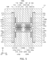
- FIG. 5 is a schematic plan view illustrating a sensor according to the first embodiment.
- a sensor 111 also includes the base body 50S, the support portion 10S, and the first member 10M.
- the first member 10M includes a first counter beam 31A and a second counter beam 32A. Except for this, the configuration of the sensor 111 may be the same as the configuration of the sensor 110.
- the configuration of the first structure 21, the first support structure 11S, the first connection structure 21c, the first connect portion 11c, and the first beam 31 in the sensor 111 may be the same as the configurations of those in the sensor 110.
- the first member 10M includes the second structure 22, the second support structure 12S, the second connect portion 12c, and the first counter beam 31A.
- the first counter beam 31A extends along the second direction D2.
- the second structure position of the second structure 22 in the second direction D2 is located between the first movable region position and a first counter beam position of the first counter beam 31A in the second direction D2.
- a first counter beam end 31Ae of the first counter beam 31A is connected to the first connection structure 21c.
- a first counter beam other end 31Af of the first counter beam 31A is connected to the supported region 10Ms.
- a second support structure position of the second support structure 12S in the second direction D2 is located between the second structure position and the support portion position.
- the second structure 22 includes the second portion 22e, the second other portion 22f, and a second intermediate portion 22m.
- the direction from the second other portion 22f to the second portion 22e is along the third direction D3.
- the second intermediate portion 22m is located between the second other portion 22f and the second portion 22e.
- the second portion 22e is connected to the first connection structure 21c.
- the second other portion 22f is connected to the first movable region 10Ma.
- the second intermediate portion 22m is connected to the second support structure 12S.
- the second connect portion 12c connects the first connection structure 21c to the second support structure 12S.
- the first connection structure 21c is located between at least a part of the second support structure 12S and at least a part of the first support structure 11S.
- the first connect portion 11c is located between the first connection structure 21c and at least a part of the first support structure 11S.
- the second connect portion 12c is located between at least a part of the second support structure 12S and the first connection structure 21c.
- the first counter beam 31A is located between the second support structure 12S and the first beam 31.
- the sensor 111 may include the first electrode 51 and the first counter electrode 51A.
- the first electrode 51 and the first counter electrode 51A are fixed to the base body 50S.
- the first member 10M may include the first beam electrode 31E connected to the first beam 31 and the first counter beam electrode 31AE connected to the first counter beam 31A.
- the first electrode 51 faces the first beam electrode 31E.
- the first counter electrode 51A is faces the first counter beam electrode 31AE.
- the controller 70 may be provided.
- the controller 70 is configured to apply the driving signal including an AC component between the first electrode 51 and the first beam electrode 31E.
- the controller 70 is configuration to detect the electric signal generated between the first counter electrode 51A and the first counter beam electrode 31AE.
- the first member 10M may include the second movable region 10Mb, the third structure 23, the third support structure 13S, the second connection structure 22c, the third connect portion 13c, and the second beam 32.
- the supported region 10Ms is located between the first movable region 10Ma and the second movable region 10Mb.
- the second beam 32 extends along the second direction D2.
- a second beam position of the second beam 32 in the second direction D2 is located between the support portion position and a second movable region position of the second movable region 10Mb in the second direction D2.
- the second end 32e of the second beam 32 is connected to the second connection structure 22c.
- the second other end 32f of the second beam 32 is connected to the supported region 10Ms.
- the third structure position of the third structure 23 in the second direction D2 is located between the second beam position and the second movable region position.
- the second connection structure position of the second connection structure 22c in the second direction D2 is located between the second beam position and the third structure position.
- the third support structure position of the third support structure 13S in the second direction D2 is located between the support portion position and the third structure position.
- the third structure 23 includes the third portion 23e, the third other portion 23f, and the third intermediate portion 23m.
- the direction from the third portion 23e to the third other portion 23f is along the third direction D3.
- the third intermediate portion 23m is located between the third portion 23e and the third other portion 23f.
- the third portion 23e is connected to the second connection structure 22c.
- the third other portion 23f is connected to the second movable region 10Mb.
- the third intermediate portion 23m is connected to the third support structure 13S.
- the third connect portion 13c connects the second connection structure 22c to the third support structure 13S.
- the first member 10M includes the fourth structure 24, the fourth support structure 14S, the fourth connect portion 14c, and the second counter beam 32A.
- the second counter beam 32A extends along the second direction D2.
- the fourth structure position of the fourth structure 24 in the second direction D2 is located between the second counter beam position of the second counter beam 32A in the second direction D2 and the second movable region position.
- the second counter beam end 32Ae of the second counter beam 32A is connected to the second connection structure 22c.
- the second counter beam other end 32Af of the second counter beam 32A is connected to the supported region 10Ms.
- the fourth support structure position of the fourth support structure 14S in the second direction D2 is located between the support portion position and the fourth structure position.
- the fourth structure 24 includes the fourth portion 24e, the fourth other portion 24f, and the fourth intermediate portion 24m.
- the direction from the fourth other portion 24f to the fourth portion 24e is along the third direction D3.
- the fourth intermediate portion 24m is located between the fourth other portion 24f and the fourth portion 24e.
- the fourth portion 24e is connected to the second connection structure 22c.
- the fourth other portion 24f is connected to the second movable region 10Mb.
- the fourth intermediate portion 24m is connected to the fourth support structure 14S.
- the fourth connect portion 14c connects the second connection structure 22c to the fourth support structure 14S.
- the second connection structure 22c is located between at least a part of the fourth support structure 14S and at least a part of the third support structure 13S.
- the third connect portion 13c is located between the second connection structure 22c and at least a part of the third support structure 13S.
- the fourth connect portion 14c is located between at least a part of the fourth support structure 14S and the second connection structure 22c.
- the second counter beam 32A is located between the fourth support structure 14S and the second beam 32.
- the sensor 111 may include the second electrode 52 and the second counter electrode 52A.
- the second electrode 52 and the second counter electrode 52A are fixed to the base body 50S.
- the first member 10M may include the second beam electrode 32E connected to the second beam 32 and the second counter beam electrode 32AE connected to the second counter beam 32A.
- the second electrode 52 faces the second beam electrode 32E.
- the second counter electrode 52A faces the second counter beam electrode 32AE.
- the controller 70 may be provided.
- the controller 70 is configured to apply the drive signal including an AC component between the second electrode 52 and the second beam electrode 32E.
- the controller 70 is configured to detect the electric signal generated between the second counter electrode 52A and the second counter beam electrode 32AE.
- the first beam 31 and the first counter beam 31A form one pair.
- the second beam 32 and the second counter beam 32A form another pair.
- the vibration amplitude at the resonance frequency of the reverse phase mode becomes large.
- the mechanical Q factor (quality factor) increases. High precision detection becomes possible.
- the first member 10M may be conductive.
- the first member 10M may include, for example, conductive silicon.
- at least one of the supported region 10Ms, the first support structure 11S, the second support structure 12S, the third support structure 13S, or the fourth support structure 14S may include a metal layer.
- high thermal conductivity can be obtained.
- a second embodiment relates to an electronic device.
- FIG. 6 is a schematic diagram illustrating an electronic device according to a second embodiment.
- an electronic device 310 includes the sensors according to the first to third embodiments and the circuit processor 170.
- the sensor 110 is drawn as the sensor.
- the circuit processor 170 is configured to control a circuit 180 based on the signal S1 obtained from the sensor.
- the circuit 180 is, for example, a control circuit for a drive device 185. According to the embodiment, for example, the circuit 180 for controlling the drive device 185 can be controlled with high accuracy.
- FIGS.7A to 7H are schematic views illustrating applications of the electronic device.
- the electronic device 310 may be at least a portion of a robot. As shown in FIG. 7B , the electronic device 310 may be at least a portion of a machining robot provided in a manufacturing plant, etc. As shown in FIG. 7C , the electronic device 310 may be at least a portion of an automatic guided vehicle inside a plant, etc. As shown in FIG. 7D , the electronic device 310 may be at least a portion of a drone (an unmanned aircraft). As shown in FIG. 7E , the electronic device 310 may be at least a portion of an airplane. As shown in FIG. 7F , the electronic device 310 may be at least a portion of a ship. As shown in FIG. 7A , the electronic device 310 may be at least a portion of a robot. As shown in FIG. 7B , the electronic device 310 may be at least a portion of a machining robot provided in a manufacturing plant, etc. As shown in FIG. 7C , the electronic device 310 may be at least a portion of an automatic
- the electronic device 310 may be at least a portion of a submarine. As shown in FIG. 7H , the electronic device 310 may be at least a portion of an automobile.
- the electronic device 310 according to the third embodiment may include, for example, at least one of a robot or a moving body.
- FIGS. 8A and 8B are schematic views illustrating applications of the electronic device.
- a sensor 430 according to the fifth embodiment includes the sensor according to one of the first to third embodiments, and a transmission/reception part 420.
- the sensor 110 is illustrated as the sensor.
- the transmission/reception part 420 is configured to transmit the signal obtained from the sensor 110 by, for example, at least one of wireless and wired methods.
- the sensor 430 is provided on, for example, a slope surface 410 such as a road 400.
- the sensor 430 can monitor the state of, for example, a facility (e.g., infrastructure).
- the sensor 430 may be, for example, a state monitoring device.
- the sensor 430 detects a change in the state of a slope surface 410 of a road 400 with high accuracy.
- the change in the state of the slope surface 410 includes, for example, at least one of a change in the inclination angle and a change in the vibration state.
- the signal (inspection result) obtained from the sensor 110 is transmitted by the transmission/reception part 420.
- the status of a facility e.g., infrastructure
- the sensor 430 is provided, for example, in a portion of a bridge 460.
- the bridge 460 is provided above the river 470.
- the bridge 460 includes at least one of a main girder 450 and a pier 440.
- the sensor 430 is provided on at least one of the main girder 450 and the pier 440.
- at least one of the angles of the main girder 450 and the pier 440 may change due to deterioration or the like.
- the vibration state may change in at least one of the main girder 450 and the pier 440.
- the sensor 430 detects these changes with high accuracy.
- the detection result can be transmitted to an arbitrary place by the transmission/reception part 420. Abnormalities can be detected effectively.
- Embodiments include, for example, the following configurations (e.g., technological proposals).
- a sensor comprising:
- the sensor according to Configuration 12 further comprising:
- An electronic device comprising:
- a sensor and an electronic device capable of improving characteristics can be provided.
Landscapes
- Physics & Mathematics (AREA)
- General Physics & Mathematics (AREA)
- Pressure Sensors (AREA)
- Micromachines (AREA)
Abstract
Description
- Embodiments described herein relate generally to a sensor and an electronic device.
- For example, there is a sensor using a MEMS structure. In the sensor, stable detection is desired.
-
-
FIG. 1 is a schematic plan view illustrating a sensor according to a first embodiment; -
FIG. 2 is a schematic cross-sectional view illustrating the sensor according to the first embodiment; -
FIG. 3 is a schematic plan view illustrating a part of the sensor according to the first embodiment; -
FIG. 4 is a schematic plan view illustrating the sensor according to the first embodiment; -
FIG. 5 is a schematic plan view illustrating a sensor according to the first embodiment; -
FIG. 6 is a schematic diagram illustrating an electronic device according to a second embodiment; -
FIGS. 7A to 7H are schematic views illustrating applications of the electronic device; and -
FIGS. 8A and 8B are schematic views illustrating applications of the electronic device. - According to one embodiment, a sensor includes a base body, a support portion fixed to the base body, and a first member supported by the support portion. A gap is provided between the base body and a part of the first member. The first member includes a supported region, a first movable region, a first structure, a first support structure, a first connection structure, a first connect portion, and a first beam. The support portion is located between the base body and the supported region in a first direction from the base body to the support portion. The first beam extends along a second direction crossing the first direction. A first beam position of the first beam in the second direction is located between a first movable region position of the first movable region in the second direction and a support portion position of the support portion in the second direction. A first end of the first beam is connected to the first connecting structure. A first other end of the first beam is connected to the supported region. A first structure position of the first structure in the second direction is located between the first movable region position and the first beam position. A first connection structure position of the first connection structure in the second direction is located between the first structure position and the first beam position. A first support structure position of the first support structure in the second direction is located between the first structure position and the support portion position. The first structure includes a first portion, a first other portion, and a first intermediate portion. A third direction from the first portion to the first other portion crosses a plane including the first direction and the second direction. The first intermediate portion is between the first portion and the first other portion. The first portion is connected to the first connection structure. The first other portion is connected to the first movable region. The first intermediate portion is connected to the first support structure. The first connect portion connects the first connection structure to the first support structure.
- Various embodiments are described below with reference to the accompanying drawings.
- The drawings are schematic and conceptual; and the relationships between the thickness and width of portions, the proportions of sizes among portions, etc., are not necessarily the same as the actual values. The dimensions and proportions may be illustrated differently among drawings, even for identical portions.
- In the specification and drawings, components similar to those described previously or illustrated in an antecedent drawing are marked with like reference numerals, and a detailed description is omitted as appropriate.
-
FIG. 1 is a schematic plan view illustrating a sensor according to the first embodiment. -
FIG. 2 is a schematic cross-sectional view illustrating the sensor according to the first embodiment. -
FIG. 2 is a cross-sectional view taken along the line A1-A2 ofFIG. 1 . - As shown in
FIGS. 1 and2 , asensor 110 according to the embodiment includes abase body 50S, asupport portion 10S and afirst member 10M. - As shown in
FIG. 2 , thesupport portion 10S is fixed to thebase body 50S. Thefirst member 10M is supported by thesupport portion 10S. A gap g1 is provided between thebase body 50S and a part of thefirst member 10M. At least a part of thefirst member 10M may be conductive. - A first direction D1 from the
base body 50S to thesupport portion 10S is defined as a Z-axis direction. One direction perpendicular to the Z-axis direction is defined as an X-axis direction. The direction perpendicular to the Z-axis direction and the X-axis direction is defined as a Y-axis direction. - As shown in
FIG. 1 , thefirst member 10M includes a supported region 10Ms, a first movable region 10Ma, afirst structure 21, afirst support structure 11S, afirst connection structure 21c, afirst connect portion 11c and afirst beam 31. - As shown in
FIG. 2 , thesupport portion 10S is provided between thebase body 50S and the supported region 10Ms in the first direction D1. - The
first beam 31 extends along a second direction D2. The second direction D2 crosses the first direction D1. The second direction D2 is, for example, the X-axis direction. - A first beam position of the
first beam 31 in the second direction D2 is located between a first movable region position of the first movable region 10Ma in the second direction D2 and a support portion position of thesupport portion 10S in the second direction D2. - A
first end 31e of thefirst beam 31 is connected to thefirst connection structure 21c. A firstother end 31f of thefirst beam 31 is connected to the supported region 10Ms. - A first structure position of the
first structure 21 in the second direction D2 is located between the first movable region position (the position of the first movable region 10Ma in the second direction D2) and the first beam position (the position of thefirst beam 31 in the second direction D2). A first connection structure position of thefirst connection structure 21c in the second direction D2 is located between the first structure position and the first beam position. A first support structure position of thefirst support structure 11S in the second direction D2 is located between the first structure position and the support portion position. - The
first structure 21 includes afirst portion 21e, a firstother portion 21f, and a firstintermediate portion 21m. A third direction D3 from thefirst portion 21e to the firstother portion 21f crosses a plane including the first direction D1 and the second direction D2. The firstintermediate portion 21m is located between thefirst portion 21e and the firstother portion 21f. - The
first portion 21e is connected to thefirst connection structure 21c. The firstother portion 21f is connected to the first movable region 10Ma. The firstintermediate portion 21m is connected to thefirst support structure 11S. - For example, the
first member 10M includes a first portion connect portion 21ec, a first other portion connect portion 21fc, and a first intermediate portion connect portion 21mc. The first portion connect portion 21ec connects thefirst portion 21e to thefirst connection structure 21c. The first other portion connect portion 21fc connects the firstother portion 21f to the first movable region 10Ma. The first intermediate portion connect portion 21mc connects the firstintermediate portion 21m to thefirst support structure 11S. - The
first connect portion 11c connects thefirst connection structure 21c to thefirst support structure 11S. - For example, the
first member 10M can move along the X-axis direction. In response to an external force, for example, the first movable region 10Ma moves along the X-axis direction. The movement of the first movable region 10Ma is transmitted to thefirst connection structure 21c by thefirst structure 21. Thefirst structure 21 is, for example, a lever. Thefirst portion 21e is, for example, a point of action. The firstother portion 21f is, for example, a point of force. The firstintermediate portion 21m is, for example, a fulcrum. - For example, stress along the X-axis direction is applied to the
first connection structure 21c. As a result, compressive stress or tensile stress is applied to thefirst beam 31. As described later, when an AC signal is applied, thefirst beam 31 vibrates. The resonance frequency of thefirst beam 31 changes according to the stress applied to thefirst beam 31. By detecting a change in the resonance frequency of thefirst beam 31, it is possible to detect an externally applied force (e.g., acceleration). - In the embodiment, the
first connection structure 21c is connected to thefirst support structure 11S by thefirst connect portion 11c. As a result, the movement of thefirst connection structure 21c is stabilized as compared with a reference example in which thefirst connection structure 21c is not connected to thefirst support structure 11S. As a result, stable detection can be achieved as compared with the reference example. A sensor that can improve detection accuracy can be provided. - As shown in
FIG. 1 , in this example, thefirst member 10M includes asecond structure 22, asecond support structure 12S, and asecond connect portion 12c. - A second structure position of the
second structure 22 in the second direction D2 is located between the first movable region position and the first beam position. A second support structure position of thesecond support structure 12S in the second direction D2 is located between the second structure position and the support portion position. - The
second structure 22 includes asecond portion 22e, a secondother portion 22f, and a secondintermediate portion 22m. A direction from the secondother portion 22f to thesecond portion 22e is along the third direction D3. The secondintermediate portion 22m is located between the secondother portion 22f and thesecond portion 22e. Thesecond portion 22e is connected to thefirst connection structure 21c. The secondother portion 22f is connected to the first movable region 10Ma. The secondintermediate portion 22m is connected to thesecond support structure 12S. - For example, the
first member 10M includes a second portion connect portion 22ec, a second other portion connect portion 22fc, and a second intermediate portion connect portion 22mc. The second portion connect portion 22ec connects thesecond portion 22e to thefirst connection structure 21c. The second other portion connect portion 22fc connects the secondother portion 22f to the first movable region 10Ma. The second intermediate portion connect portion 22mc connects the secondintermediate portion 22m to thesecond support structure 12S. - The
second connect portion 12c connects thefirst connection structure 21c to thesecond support structure 12S. By thefirst connection structure 21c being connected to thesecond support structure 12S, thefirst connection structure 21c becomes stable. - In the third direction D3, the
first connection structure 21c is located between at least a part of thesecond support structure 12S and at least a part of thefirst support structure 11S. In the third direction D3, thefirst connect portion 11c is located between thefirst connection structure 21c and at least a part of thefirst support structure 11S. In the third direction D3, thesecond connect portion 12c is located between at least a part of thesecond support structure 12S and thefirst connection structure 21c. - For example, the movement of the first movable region 10Ma is transmitted to the
first connection structure 21c by thesecond structure 22. Thesecond structure 22 is, for example, a lever. Thesecond portion 22e is, for example, a point of action. The secondother portion 22f is, for example, a point of force. The secondintermediate portion 22m is, for example, a fulcrum. - By providing the
second structure 22 and thesecond support structure 12S, thefirst connection structure 21c is stabilized. More stable detection becomes possible. - As shown in
FIG. 1 , in this example, thefirst member 10M includes a second movable region 10Mb, athird structure 23, athird support structure 13S, asecond connection structure 22c, athird connect portion 13c, and asecond beam 32. In the second direction D2, the supported region 10Ms is located between the first movable region 10Ma and the second movable region 10Mb. - The
second beam 32 extends along the second direction D2. A second beam position of thesecond beam 32 in the second direction D2 is located between the support portion position and a second movable region position of the second movable region 10Mb in the second direction D2. Asecond end 32e of thesecond beam 32 is connected to thesecond connection structure 22c. A secondother end 32f of thesecond beam 32 is connected to the supported region 10Ms. - A third structure position of the
third structure 23 in the second direction D2 is located between the second beam position and the second movable region position. A second connection structure position of thesecond connection structure 22c in the second direction D2 is located between the second beam position and the third structure position. A third support structure position of thethird support structure 13S in the second direction D2 is located between the support portion position and the third structure position. - The
third structure 23 includes athird portion 23e, a thirdother portion 23f, and a thirdintermediate portion 23m. A direction from thethird portion 23e to the thirdother portion 23f is along the third direction D3. The thirdintermediate portion 23m is located between thethird portion 23e and the thirdother portion 23f. - The
third portion 23e is connected to thesecond connection structure 22c. The thirdother portion 23f is connected to the second movable region 10Mb. The thirdintermediate portion 23m is connected to thethird support structure 13S. - For example, the
first member 10M includes a third portion connect portion 23ec, a third other portion connect portion 23fc, and a third intermediate portion connect portion 23mc. The third portion connect portion 23ec connects thethird portion 23e to thesecond connection structure 22c. The third other portion connect portion 23fc connects the thirdother portion 23f to the second movable region 10Mb. The third intermediate portion connect portion 23mc connects the thirdintermediate portion 23m to thethird support structure 13S. - The
third connect portion 13c connects thesecond connection structure 22c to thethird support structure 13S. By thesecond connection structure 22c being connected to thethird support structure 13S, thesecond connection structure 22c is stabilized. - For example, the movement of the second movable region 10Mb is transmitted to the
second connection structure 22c by thethird structure 23. Thethird structure 23 is, for example, a lever. Thethird portion 23e is, for example, a point of action. The thirdother portion 23f is, for example, a point of force. The thirdintermediate portion 23m is, for example, a fulcrum. - As shown in
FIG. 1 , in this example, thefirst member 10M includes afourth structure 24, afourth support structure 14S, and afourth connect portion 14c. A fourth structure position thefourth structure 24 in the second direction D2 is located between the second beam position and the second movable region position. A fourth support structure position of thefourth support structure 14S in the second direction D2 is located between the support portion position and the fourth structure position. - The
fourth structure 24 includes afourth portion 24e, a fourthother portion 24f, and a fourthintermediate portion 24m. A direction from the fourthother portion 24f to thefourth portion 24e is along the third direction D3. The fourthintermediate portion 24m is located between the fourthother portion 24f and thefourth portion 24e. Thefourth portion 24e is connected to thesecond connection structure 22c. The fourthother portion 24f is connected to the second movable region 10Mb. The fourthintermediate portion 24m is connected to thefourth support structure 14S. - For example, the
first member 10M includes a fourth portion connect portion 24ec, a fourth other portion connect portion 24fc, and a fourth intermediate portion connect portion 24mc. The fourth portion connect portion 24ec connects thefourth portion 24e to thesecond connection structure 22c. The fourth other portion connect portion 24fc connects the fourthother portion 24f to the second movable region 10Mb. The fourth intermediate portion connect portion 24mc connects the fourthintermediate portion 24m to thefourth support structure 14S. - The
fourth connect portion 14c connects thesecond connection structure 22c to thefourth support structure 14S. By thesecond connection structure 22c beings connected to thefourth support structure 14S, thesecond connection structure 22c is stabilized. - In the third direction D3, the
second connection structure 22c is located between at least a part of thefourth support structure 14S and at least a part of thethird support structure 13S. In the third direction D3, thethird connect portion 13c is located between thesecond connection structure 22c and at least a part of thethird support structure 13S. In the third direction D3, thefourth connect portion 14c is located between at least a part of thefourth support structure 14S and thesecond connection structure 22c. - For example, the movement of the second movable region 10Mb is transmitted to the
second connection structure 22c by thefourth structure 24. Thefourth structure 24 is, for example, a lever. Thefourth portion 24e is, for example, a point of action. The fourthother portion 24f is, for example, a point of force. The fourthintermediate portion 24m is, for example, a fulcrum. -
FIG. 3 is a schematic plan view illustrating a part of the sensor according to the first embodiment. - In
FIG. 3 , a portion ofFIG. 1 is shown enlarged. - As shown in
FIG. 3 , thesensor 110 may include afirst electrode 51 and afirst counter electrode 51A. Thefirst electrode 51 is fixed to thebase body 50S. Thefirst counter electrode 51A is fixed to thebase body 50S. - The
first member 10M further includes afirst beam electrode 31E connected to thefirst beam 31 and a first counter beam electrode 31AE connected to thefirst beam 31. For example, in the third direction D3, thefirst beam 31 is located between the first counter beam electrode 31AE and thefirst beam electrode 31E. Thefirst electrode 51 faces thefirst beam electrode 31E. Thefirst counter electrode 51A faces the first counter beam electrode 31AE. - As shown in
FIG. 3 , thecontroller 70 may be provided. Thecontroller 70 may be included in thesensor 110. Thecontroller 70 may be provided separately from thesensor 110. - The
controller 70 is electrically connected to thefirst electrode 51, thefirst counter electrode 51A, thefirst beam electrode 31E, and the first counter beam electrode 31AE. For example, thefirst beam electrode 31E and the first counter beam electrode 31AE are electrically connected to thefirst member 10M (for example, the supported region 10Ms). - The
controller 70 is configured to apply a driving signal including an AC component between thefirst electrode 51 and thefirst beam electrode 31E. Thecontroller 70 is configured to detect an electric signal generated between thefirst counter electrode 51A and the first counter beam electrode 31AE. By detecting a change in the electric signal generated between thefirst counter electrode 51A and the first counter beam electrode 31AE, an external force can be detected. - As shown in
FIG. 3 , thesensor 110 may include asecond electrode 52 and asecond counter electrode 52A. Thesecond electrode 52 is fixed to thebase body 50S. Thesecond counter electrode 52A is fixed to thebase body 50S. - The
first member 10M may further include asecond beam electrode 32E connected to thesecond beam 32 and a second counter beam electrode 32AE connected to thesecond beam 32. In the third direction D3, thesecond beam 32 is located between the second counter beam electrode 32AE and thesecond beam electrode 32E. Thesecond electrode 52 faces thesecond beam electrode 32E. Thesecond counter electrode 52A faces the second counter beam electrode 32AE. For example, thesecond beam electrode 32E and the second counter beam electrode 32AE are electrically connected to thefirst member 10M (for example, the supported region 10Ms). - The
controller 70 is configured to apply the drive signal including an AC component between thesecond electrode 52 and thesecond beam electrode 32E. Thecontroller 70 is configured to detect an electric signal generated between thesecond counter electrode 52A and the second counter beam electrode 32AE. - As shown in
FIG. 1 , thefirst member 10M may include a third movable region 10Mc and a fourth movable region 10Md. A direction from the fourth movable region 10Md to the third movable region 10Mc is along the third direction D3. The third movable region 10Mc and the fourth movable region 10Md are continuous with the first movable region 10Ma and the second movable region 10Mb. The supported region 10Ms is provided between the third movable region 10Mc and the fourth movable region 10Md. - As shown in
FIG. 3 , thefirst member 10M may further include a first movable region connectportion 11A. A position of thefirst support structure 11S in the third direction D3 is located between a position of the supported region 10Ms in the third direction D3 and a position of the third movable region 10Mc in the third direction D3. The first movable region connectportion 11A connects thefirst support structure 11S to the third movable region 10Mc. By providing the first movable region connectportion 11A, the displacement of thefirst member 10M along the second direction D2 is stabilized. - As shown in
FIG. 3 , thefirst member 10M may further include a second movable region connectportion 12A. A position of thesecond support structure 12S in the third direction D3 is located between a position of the fourth movable region 10Md in the third direction D3 and the position of the supported region 10Ms in the third direction D3. The second movable region connectportion 12A connects thesecond support structure 12S to the fourth movable region 10Md. By providing the second movable region connectportion 12A, the displacement of thefirst member 10M along the second direction D2 is stabilized. - As shown in
FIG. 3 , thefirst member 10M may further include a third movable region connectportion 13A. A position of thethird support structure 13S in the third direction D3 is located between the position of the supported region 10Ms in the third direction D3 and the position of the third movable region 10Mc in the third direction D3. The third movable region connectportion 13A connects thethird support structure 13S to the third movable region 10Mc. By providing the third movable region connectportion 13A, the displacement of thefirst member 10M along the second direction D2 is stabilized. - As shown in
FIG. 3 , thefirst member 10M may further include a fourth movable region connectportion 14A. A position of thefourth support structure 14S in the third direction D3 is located between the position of the fourth movable region 10Md in the third direction D3 and the position of the supported region 10Ms in the third direction D3. The fourth movable region connectportion 14A connects thefourth support structure 14S to the fourth movable region 10Md. By providing the fourth movable region connectportion 14A, the displacement of thefirst member 10M along the second direction D2 is stabilized. -
FIG. 4 is a schematic plan view illustrating the sensor according to the first embodiment. - In
FIG. 4 , a portion ofFIG. 1 is shown enlarged. - As shown in
FIG. 4 , a length of thefirst connect portion 11c along the third direction D3 is defined as a first length L1. A length of thefirst connect portion 11c along the second direction D2 is defined as a second length L2. For example, the first length L1 is longer than the second length L2. Thefirst connection structure 21c connected to thefirst connect portion 11c can be easily displaced along the second direction D2. The position of thefirst connection structure 21c in the third direction D3 becomes stable. - As shown in
FIG. 4 , a distance between thefirst portion 21e and the firstintermediate portion 21m along the third direction D3 is defined as a first distance d1. A distance between the firstintermediate portion 21m and the firstother portion 21f along the third direction D3 is defined as a second distance d2. The first distance d1 is shorter than the second distance d2. Thefirst structure 21 efficiently transmits, for example, the displacement of the first movable region 10Ma along the second direction D2 to thefirst connection structure 21c. - The configuration relating to the
first connect portion 11c can be applied to thesecond connect portion 12c, thethird connect portion 13c, and thefourth connect portion 14c. The configuration relating to thefirst structure 21 can be applied to thesecond structure 22, thethird structure 23 and thefourth structure 24. -
FIG. 5 is a schematic plan view illustrating a sensor according to the first embodiment. - As shown in
FIG. 5 , asensor 111 according to the embodiment also includes thebase body 50S, thesupport portion 10S, and thefirst member 10M. In thesensor 111, thefirst member 10M includes afirst counter beam 31A and asecond counter beam 32A. Except for this, the configuration of thesensor 111 may be the same as the configuration of thesensor 110. - The configuration of the
first structure 21, thefirst support structure 11S, thefirst connection structure 21c, thefirst connect portion 11c, and thefirst beam 31 in thesensor 111 may be the same as the configurations of those in thesensor 110. - In the
sensor 111, thefirst member 10M includes thesecond structure 22, thesecond support structure 12S, thesecond connect portion 12c, and thefirst counter beam 31A. Thefirst counter beam 31A extends along the second direction D2. The second structure position of thesecond structure 22 in the second direction D2 is located between the first movable region position and a first counter beam position of thefirst counter beam 31A in the second direction D2. A first counter beam end 31Ae of thefirst counter beam 31A is connected to thefirst connection structure 21c. A first counter beam other end 31Af of thefirst counter beam 31A is connected to the supported region 10Ms. A second support structure position of thesecond support structure 12S in the second direction D2 is located between the second structure position and the support portion position. - The
second structure 22 includes thesecond portion 22e, the secondother portion 22f, and a secondintermediate portion 22m. The direction from the secondother portion 22f to thesecond portion 22e is along the third direction D3. The secondintermediate portion 22m is located between the secondother portion 22f and thesecond portion 22e. Thesecond portion 22e is connected to thefirst connection structure 21c. The secondother portion 22f is connected to the first movable region 10Ma. The secondintermediate portion 22m is connected to thesecond support structure 12S. - The
second connect portion 12c connects thefirst connection structure 21c to thesecond support structure 12S. In the third direction D3, thefirst connection structure 21c is located between at least a part of thesecond support structure 12S and at least a part of thefirst support structure 11S. In the third direction D3, thefirst connect portion 11c is located between thefirst connection structure 21c and at least a part of thefirst support structure 11S. In the third direction D3, thesecond connect portion 12c is located between at least a part of thesecond support structure 12S and thefirst connection structure 21c. In the third direction D3, thefirst counter beam 31A is located between thesecond support structure 12S and thefirst beam 31. - As shown in
FIG. 5 , thesensor 111 may include thefirst electrode 51 and thefirst counter electrode 51A. Thefirst electrode 51 and thefirst counter electrode 51A are fixed to thebase body 50S. Thefirst member 10M may include thefirst beam electrode 31E connected to thefirst beam 31 and the first counter beam electrode 31AE connected to thefirst counter beam 31A. Thefirst electrode 51 faces thefirst beam electrode 31E. Thefirst counter electrode 51A is faces the first counter beam electrode 31AE. - As described with reference to
FIG. 3 , thecontroller 70 may be provided. Thecontroller 70 is configured to apply the driving signal including an AC component between thefirst electrode 51 and thefirst beam electrode 31E. Thecontroller 70 is configuration to detect the electric signal generated between thefirst counter electrode 51A and the first counter beam electrode 31AE. - As shown in
FIG. 5 , thefirst member 10M may include the second movable region 10Mb, thethird structure 23, thethird support structure 13S, thesecond connection structure 22c, thethird connect portion 13c, and thesecond beam 32. In the second direction D2, the supported region 10Ms is located between the first movable region 10Ma and the second movable region 10Mb. - The
second beam 32 extends along the second direction D2. A second beam position of thesecond beam 32 in the second direction D2 is located between the support portion position and a second movable region position of the second movable region 10Mb in the second direction D2. Thesecond end 32e of thesecond beam 32 is connected to thesecond connection structure 22c. The secondother end 32f of thesecond beam 32 is connected to the supported region 10Ms. - The third structure position of the
third structure 23 in the second direction D2 is located between the second beam position and the second movable region position. The second connection structure position of thesecond connection structure 22c in the second direction D2 is located between the second beam position and the third structure position. The third support structure position of thethird support structure 13S in the second direction D2 is located between the support portion position and the third structure position. - The
third structure 23 includes thethird portion 23e, the thirdother portion 23f, and the thirdintermediate portion 23m. The direction from thethird portion 23e to the thirdother portion 23f is along the third direction D3. The thirdintermediate portion 23m is located between thethird portion 23e and the thirdother portion 23f. Thethird portion 23e is connected to thesecond connection structure 22c. The thirdother portion 23f is connected to the second movable region 10Mb. The thirdintermediate portion 23m is connected to thethird support structure 13S. Thethird connect portion 13c connects thesecond connection structure 22c to thethird support structure 13S. - As shown in
FIG. 5 , thefirst member 10M includes thefourth structure 24, thefourth support structure 14S, thefourth connect portion 14c, and thesecond counter beam 32A. Thesecond counter beam 32A extends along the second direction D2. The fourth structure position of thefourth structure 24 in the second direction D2 is located between the second counter beam position of thesecond counter beam 32A in the second direction D2 and the second movable region position. The second counter beam end 32Ae of thesecond counter beam 32A is connected to thesecond connection structure 22c. The second counter beam other end 32Af of thesecond counter beam 32A is connected to the supported region 10Ms. The fourth support structure position of thefourth support structure 14S in the second direction D2 is located between the support portion position and the fourth structure position. - The
fourth structure 24 includes thefourth portion 24e, the fourthother portion 24f, and the fourthintermediate portion 24m. The direction from the fourthother portion 24f to thefourth portion 24e is along the third direction D3. The fourthintermediate portion 24m is located between the fourthother portion 24f and thefourth portion 24e. Thefourth portion 24e is connected to thesecond connection structure 22c. The fourthother portion 24f is connected to the second movable region 10Mb. The fourthintermediate portion 24m is connected to thefourth support structure 14S. - The
fourth connect portion 14c connects thesecond connection structure 22c to thefourth support structure 14S. In the third direction D3, thesecond connection structure 22c is located between at least a part of thefourth support structure 14S and at least a part of thethird support structure 13S. In the third direction D3, thethird connect portion 13c is located between thesecond connection structure 22c and at least a part of thethird support structure 13S. In the third direction D3, thefourth connect portion 14c is located between at least a part of thefourth support structure 14S and thesecond connection structure 22c. In the third direction D3, thesecond counter beam 32A is located between thefourth support structure 14S and thesecond beam 32. - As shown in
FIG. 5 , thesensor 111 may include thesecond electrode 52 and thesecond counter electrode 52A. Thesecond electrode 52 and thesecond counter electrode 52A are fixed to thebase body 50S. Thefirst member 10M may include thesecond beam electrode 32E connected to thesecond beam 32 and the second counter beam electrode 32AE connected to thesecond counter beam 32A. Thesecond electrode 52 faces thesecond beam electrode 32E. Thesecond counter electrode 52A faces the second counter beam electrode 32AE. - As described with reference to
FIG. 3 , thecontroller 70 may be provided. Thecontroller 70 is configured to apply the drive signal including an AC component between thesecond electrode 52 and thesecond beam electrode 32E. Thecontroller 70 is configured to detect the electric signal generated between thesecond counter electrode 52A and the second counter beam electrode 32AE. - In the
sensor 111, thefirst beam 31 and thefirst counter beam 31A form one pair. Thesecond beam 32 and thesecond counter beam 32A form another pair. For example, the vibration amplitude at the resonance frequency of the reverse phase mode becomes large. The mechanical Q factor (quality factor) increases. High precision detection becomes possible. - As described above, at least a part of the
first member 10M may be conductive. Thefirst member 10M may include, for example, conductive silicon. For example, at least one of the supported region 10Ms, thefirst support structure 11S, thesecond support structure 12S, thethird support structure 13S, or thefourth support structure 14S may include a metal layer. For example, high thermal conductivity can be obtained. - A second embodiment relates to an electronic device.
-
FIG. 6 is a schematic diagram illustrating an electronic device according to a second embodiment. - As shown in
FIG. 6 , anelectronic device 310 according to the embodiment includes the sensors according to the first to third embodiments and thecircuit processor 170. In the example ofFIG. 6 , thesensor 110 is drawn as the sensor. Thecircuit processor 170 is configured to control acircuit 180 based on the signal S1 obtained from the sensor. Thecircuit 180 is, for example, a control circuit for adrive device 185. According to the embodiment, for example, thecircuit 180 for controlling thedrive device 185 can be controlled with high accuracy. -
FIGS.7A to 7H are schematic views illustrating applications of the electronic device. - As shown in
FIG. 7A , theelectronic device 310 may be at least a portion of a robot. As shown inFIG. 7B , theelectronic device 310 may be at least a portion of a machining robot provided in a manufacturing plant, etc. As shown inFIG. 7C , theelectronic device 310 may be at least a portion of an automatic guided vehicle inside a plant, etc. As shown inFIG. 7D , theelectronic device 310 may be at least a portion of a drone (an unmanned aircraft). As shown inFIG. 7E , theelectronic device 310 may be at least a portion of an airplane. As shown inFIG. 7F , theelectronic device 310 may be at least a portion of a ship. As shown inFIG. 7G , theelectronic device 310 may be at least a portion of a submarine. As shown inFIG. 7H , theelectronic device 310 may be at least a portion of an automobile. Theelectronic device 310 according to the third embodiment may include, for example, at least one of a robot or a moving body. -
FIGS. 8A and 8B are schematic views illustrating applications of the electronic device. - As shown in
FIG. 8A , asensor 430 according to the fifth embodiment includes the sensor according to one of the first to third embodiments, and a transmission/reception part 420. In the example ofFIG. 8A , thesensor 110 is illustrated as the sensor. The transmission/reception part 420 is configured to transmit the signal obtained from thesensor 110 by, for example, at least one of wireless and wired methods. Thesensor 430 is provided on, for example, aslope surface 410 such as aroad 400. Thesensor 430 can monitor the state of, for example, a facility (e.g., infrastructure). Thesensor 430 may be, for example, a state monitoring device. - For example, the
sensor 430 detects a change in the state of aslope surface 410 of aroad 400 with high accuracy. The change in the state of theslope surface 410 includes, for example, at least one of a change in the inclination angle and a change in the vibration state. The signal (inspection result) obtained from thesensor 110 is transmitted by the transmission/reception part 420. The status of a facility (e.g., infrastructure) can be monitored, for example, continuously. - As shown in
FIG. 8B , thesensor 430 is provided, for example, in a portion of abridge 460. Thebridge 460 is provided above theriver 470. For example, thebridge 460 includes at least one of amain girder 450 and apier 440. Thesensor 430 is provided on at least one of themain girder 450 and thepier 440. For example, at least one of the angles of themain girder 450 and thepier 440 may change due to deterioration or the like. For example, the vibration state may change in at least one of themain girder 450 and thepier 440. Thesensor 430 detects these changes with high accuracy. The detection result can be transmitted to an arbitrary place by the transmission/reception part 420. Abnormalities can be detected effectively. - Embodiments include, for example, the following configurations (e.g., technological proposals).
- A sensor, comprising:
- a base body;
- a support portion fixed to the base body; and
- a first member supported by the support portion,
- a gap being provided between the base body and a part of the first member,
- the first member including a supported region, a first movable region, a first structure, a first support structure, a first connection structure, a first connect portion, and a first beam,
- the support portion being located between the base body and the supported region in a first direction from the base body to the support portion,
- the first beam extending along a second direction crossing the first direction,
- a first beam position of the first beam in the second direction being located between a first movable region position of the first movable region in the second direction and a support portion position of the support portion in the second direction,
- a first end of the first beam being connected to the first connecting structure,
- a first other end of the first beam being connected to the supported region,
- a first structure position of the first structure in the second direction being located between the first movable region position and the first beam position,
- a first connection structure position of the first connection structure in the second direction being located between the first structure position and the first beam position,
- a first support structure position of the first support structure in the second direction being located between the first structure position and the support portion position,
- the first structure including a first portion, a first other portion, and a first intermediate portion,
- a third direction from the first portion to the first other portion crossing a plane including the first direction and the second direction,
- the first intermediate portion being between the first portion and the first other portion,
- The first portion being connected to the first connection structure,
- the first other portion being connected to the first movable region,
- the first intermediate portion being connected to the first support structure, and
- the first connect portion connecting the first connection structure to the first support structure.
- The sensor according to Configuration 1, wherein a first length of the first connect portion along the third direction is longer than a second length of the first connect portion along the second direction.
- The sensor according to Configuration 1 or 2, wherein a first distance between the first portion and the first intermediate portion along the third direction is shorter than a second distance between the first intermediate portion and the first other portion along the third direction.
- The sensor according to any one of Configurations 1 to 3, wherein
the first member includes: - a first portion connect portion connecting the first portion to the first connection structure;
- a first other portion connect portion connecting the first other portion to the first movable region; and
- a first intermediate portion connect portion connecting the first intermediate portion to the first support structure.
- The sensor according to any one of Configurations 1 to 4, wherein
- the first member includes a second structure, a second support structure, and a second connect portion,
- a second structure position of the second structure in the second direction is located between the first movable region position and the first beam position,
- a second support structure position of the second support structure in the second direction is located between the second structure position and the support portion position,
- the second structure includes a second portion, a second other portion, and a second intermediate portion,
- a direction from the second other portion to the second portion is along the third direction,
- the second intermediate portion is located between the second other portion and the second portion,
- the second portion is connected to the first connection structure,
- the second other portion is connected to the first movable region,
- the second intermediate portion is connected to the second support structure,
- the second connect portion connects the first connection structure to the second support structure,
- in the third direction, the first connection structure is located between at least a part of the second support structure and at least a part of the first support structure,
- in the third direction, the first connect portion is located between the first connection structure and the at least the part of the first support structure, and
- in the third direction, the second connect portion is located between the at least the part of the second support structure and the first connection structure.
- The sensor according to Configuration 5, further comprising:
- a first electrode fixed to the base body; and
- a first counter electrode fixed to the base body,
- the first member further including a first beam electrode connected to the first beam, and a first counter beam electrode connected to the first beam,
- in the third direction, the first beam being located between the first counter beam electrode and the first beam electrode,
- the first electrode facing the first beam electrode, and
- the first counter electrode facing the first counter beam electrode.
- The sensor according to Configuration 6, further comprising:
- a controller,
- the controller being configured to apply a driving signal including an AC component between the first electrode and the first beam electrode, and
- the controller being configured to detect an electrical signal generated between the first counter electrode and the first counter beam electrode.
- The sensor according to Configuration 5, wherein
- the first member includes a second movable region, a third structure, a third support structure, a second connection structure, a third connect portion, and a second beam,
- in the second direction, the supported region is located between the first movable region and the second movable region,
- the second beam extends along the second direction,
- a second beam position of the second beam in the second direction is located between the support portion region and a second movable region position of the second movable region in the second direction,
- a second end of the second beam is connected to the second connection structure,
- a second end of the second beam is connected to the supported region,
- a third structure position of the third structure in the second direction is located between the second beam position and the second movable region position,
- a second connection structure position of the second connection structure in the second direction is located between the second beam position and the third structure position,
- a third support structure position of the third support structure in the second direction is located between the support portion position and the third structure position,
- the third structure includes a third portion, a third other portion, and a third intermediate portion,
- a direction from the third portion to the third other portion is along the third direction;
- the third intermediate portion is located between the third portion and the third other portion,
- the third portion is connected to the second connection structure,
- the third other portion is connected to the second movable region,
- the third intermediate portion is connected to the third support structure, and
- the third connect portion connects the second connection structure to the third support structure.
- The sensor according to Configuration 8, wherein
- the first member includes a fourth structure, a fourth support structure, and a fourth connect portion,
- a fourth structure position of the fourth structure in the second direction is located between the second beam position and the second movable region position,
- a fourth support structure position of the fourth support structure in the second direction is between the support portion position and the fourth structure position,
- the fourth structure includes a fourth portion, a fourth other portion, and a fourth intermediate portion,
- a direction from the fourth other portion to the fourth portion is along the third direction,
- the fourth intermediate portion is located between the fourth other portion and the fourth portion,
- the fourth portion is connected to the second connection structure,
- the fourth other portion is connected to the second movable region,
- the fourth intermediate portion is connected to the fourth support structure,
- the fourth connect portion connects the second connection structure to the fourth support structure,
- in the third direction, the second connection structure is between at least a part of the fourth support structure and at least a part of the third support structure,
- in the third direction, the third connect portion is located between the second connection structure and the at least the part of the third support structure, and
- in the third direction, the fourth connect portion is located between the at least the part of the fourth support structure and the second connection structure.
- The sensor according to Configuration 9, further comprising:
- a second electrode fixed to the base body; and
- a second counter electrode fixed to the base body,
- the first member further including a second beam electrode connected to the second beam, and a second counter beam electrode connected to the second beam,
- in the third direction, the second beam being located between the second counter beam electrode and the second beam electrode,
- the second electrode facing the second beam electrode, and
- the second counter electrode facing the second counter beam electrode.
- The sensor according to Configuration 10, further comprising
- a controller,
- the controller being configured to apply a drive signal including an AC component between the second electrode and the second beam electrode, and
- the controller being configured to detect an electrical signal generated between the second counter electrode and the second counter beam electrode.
- The sensor according to any one of Configurations 1 to 4, wherein
- the first member includes a second structure, a second support structure, a second connect portion, and a first counter beam,
- the first counter beam extends along the second direction,
- a second structure position of the second structure in the second direction is between the first movable region position and a first counter beam position of the first counter beam in the second direction,
- a first counter beam end of the first counter beam is connected to the first connecting structure,
- a first counter beam other end of the first counter beam is connected to the supported region,
- a second support structure position of the second support structure in the second direction is located between the second structure position and the support portion position,
- the second structure includes a second portion, a second other portion, and a second intermediate portion,
- a direction from the second other portion to the second portion is along the third direction,
- the second intermediate portion is located between the second other portion and the second portion,
- the second portion is connected to the first connection structure,
- the second other portion is connected to the first movable region,
- the second intermediate portion is connected to the second support structure,
- the second connect portion connects the first connection structure to the second support structure,
- in the third direction, the first connection structure is located between at least a part of the second support structure and at least a part of the first support structure,
- in the third direction, the first connect portion is located between the first connection structure and the at least the part of the first support structure,
- in the third direction, the second connect portion is located between the at least the part of the second support structure and the first connection structure, and
- in the third direction, the first counter beam is located between the second support structure and the first beam.
- The sensor according to Configuration 12, further comprising:
- a first electrode fixed to the base body; and
- a first counter electrode fixed to the base body,
- the first member further including a first beam electrode connected to the first beam, and a first counter beam electrode connected to the first counter beam,
- the first electrode facing the first beam electrode, and
- the first counter electrode facing the first counter beam electrode.
- The sensor according to Configuration 13, further comprising
- a controller,
- the controller being configured apply a driving signal including an AC component between the first electrode and the first beam electrode, and
- the controller being configured to detect an electrical signal generated between the first counter electrode and the first counter beam electrode.
- The sensor according to any one of Configurations 12 to 14, wherein
- the first member includes a second movable region, a third structure, a third support structure, a second connection structure, a third connect portion, and a second beam,
- in the second direction, the supported region is located between the first movable region and the second movable region,
- the second beam extends along the second direction,
- a second beam position of the second beam in the second direction is located between the support portion position and a second movable region position of the second movable region in the second direction,
- a second end of the second beam is connected to the second connection structure,
- a second other end of the second beam is connected to the supported region,
- a third structure position of the third structure in the second direction is located between the second beam position and the second movable region position,
- a second connection structure position of the second connection structure in the second direction is between the second beam position and the third structure position,
- a third support structure position of the third support structure in the second direction is located between the support portion position and the third structure position,
- the third structure includes a third portion, a third other portion, and a third intermediate portion,
- a direction from the third portion to the third other portion is along the third direction,
- the third intermediate portion is located between the third portion and the third other portion,
- the third portion is connected to the second connection structure,
- the third other portion is connected to the second movable region,
- the third intermediate portion is connected to the third support structure,
- the third connect portion connects the second connection structure to the third support structure,
- the first member includes a fourth structure, a fourth support structure, a fourth connect portion, and a second counter beam
- the second counter beam extends along the second direction,
- a fourth structure position of the fourth structure in the second direction is located between a second counter beam position of the second counter beam in the second direction and the second movable region position,
- a second counter beam end of the second counter beam is connected to the second connecting structure,
- a second counter beam other end of the second counter beam is connected to the supported region,
- a fourth support structure position of the fourth support structure in the second direction is located between the support portion position and the fourth structure position,
- the fourth structure includes a fourth portion, a fourth other portion, and a fourth intermediate portion,
- a direction from the fourth other portion to the fourth portion is along the third direction,
- the fourth intermediate portion is located between the fourth other portion and the fourth portion,
- the fourth portion is connected to the second connection structure,
- the fourth other portion is connected to the second movable region,
- the fourth intermediate portion is connected to the fourth support structure,
- the fourth connection portion connects the second connection structure to the fourth support structure,
- in the third direction, the second connection structure is located between at least a part of the fourth support structure and at least a part of the third support structure,
- in the third direction, the third connection portion is located between the second connection structure and the at least the part of the third support structure,
- in the third direction, the fourth connection portion is located between the at least the part of the fourth support structure and the second connection structure, and
- in the third direction, the second counter beam is located between the fourth support structure and the second beam.
- The sensor according to Configuration 15, wherein
- the first member further includes a fourth movable region and a fourth movable region connect portion,
- a position of the fourth support structure in the third direction is located between a position of the fourth movable region in the third direction and a position of the supported region in the third direction, and
- the fourth movable region connect portion connects the fourth support structure to the fourth movable region.
- The sensor according to Configuration 8, wherein
- the first member further includes a third movable region and a third movable region connect portion,
- a position of the third support structure in the third direction is located between a position of the supported region in the third direction and a position of the third movable region in the third direction, and
- the third movable region connect portion connects the third support structure to the third movable region.
- The sensor according to Configuration 5, wherein
- the first member further includes a fourth movable region and a second movable region connect portion; and
- a position of the second support structure in the third direction is located between a position of the fourth movable region in the third direction and a position of the supported region in the third direction.
- The sensor according to Configuration 1, wherein
- the first member further includes a third movable region and a first movable region connect portion,
- a position of the first support structure in the third direction is located between a position of the supported region in the third direction and a position of the third movable region in the third direction, and
- the first movable region connect portion connects the first support structure to the third movable region.
- An electronic device, comprising:
- the sensor according to any one of Configurations 1 to 19; and
- a circuit controller configured to control a circuit based on a signal obtained from the sensor.
- According to embodiments, a sensor and an electronic device capable of improving characteristics can be provided.
- Hereinabove, exemplary embodiments of the invention are described with reference to specific examples. However, the embodiments of the invention are not limited to these specific examples. For example, one skilled in the art may similarly practice the invention by appropriately selecting specific configurations of components included in sensors such as base bodies, support portions, first portions, controllers, etc., from known art. Such practice is included in the scope of the invention to the extent that similar effects thereto are obtained.
- Further, any two or more components of the specific examples may be combined within the extent of technical feasibility and are included in the scope of the invention to the extent that the purport of the invention is included.
- Moreover, all sensors and electronic devices practicable by an appropriate design modification by one skilled in the art based on the sensors and the electronic devices described above as embodiments of the invention also are within the scope of the invention to the extent that the purport of the invention is included.
- Various other variations and modifications can be conceived by those skilled in the art within the spirit of the invention, and it is understood that such variations and modifications are also encompassed within the scope of the invention.
- While certain embodiments have been described, these embodiments have been presented by way of example only, and are not intended to limit the scope of the inventions. Indeed, the novel embodiments described herein may be embodied in a variety of other forms; furthermore, various omissions, substitutions and changes in the form of the embodiments described herein may be made without departing from the spirit of the inventions. The accompanying claims and their equivalents are intended to cover such forms or modifications as would fall within the scope and spirit of the invention.
Claims (15)
- A sensor, comprising:a base body;a support portion fixed to the base body; anda first member supported by the support portion,a gap being provided between the base body and a part of the first member,the first member including a supported region, a first movable region, a first structure, a first support structure, a first connection structure, a first connect portion, and a first beam,the support portion being located between the base body and the supported region in a first direction from the base body to the support portion,the first beam extending along a second direction crossing the first direction,a first beam position of the first beam in the second direction being located between a first movable region position of the first movable region in the second direction and a support portion position of the support portion in the second direction,a first end of the first beam being connected to the first connecting structure,a first other end of the first beam being connected to the supported region,a first structure position of the first structure in the second direction being located between the first movable region position and the first beam position,a first connection structure position of the first connection structure in the second direction being located between the first structure position and the first beam position,a first support structure position of the first support structure in the second direction being located between the first structure position and the support portion position,the first structure including a first portion, a first other portion, and a first intermediate portion,a third direction from the first portion to the first other portion crossing a plane including the first direction and the second direction,the first intermediate portion being between the first portion and the first other portion,The first portion being connected to the first connection structure,the first other portion being connected to the first movable region,the first intermediate portion being connected to the first support structure, andthe first connect portion connecting the first connection structure to the first support structure.
- The sensor according to claim 1, wherein a first length of the first connect portion along the third direction is longer than a second length of the first connect portion along the second direction.
- The sensor according to claim 1 or 2, wherein a first distance between the first portion and the first intermediate portion along the third direction is shorter than a second distance between the first intermediate portion and the first other portion along the third direction.
- The sensor according to any one of claims 1-3, wherein
the first member includes:a first portion connect portion connecting the first portion to the first connection structure;a first other portion connect portion connecting the first other portion to the first movable region; anda first intermediate portion connect portion connecting the first intermediate portion to the first support structure. - The sensor according to any one of claims 1-4, whereinthe first member includes a second structure, a second support structure, and a second connect portion,a second structure position of the second structure in the second direction is located between the first movable region position and the first beam position,a second support structure position of the second support structure in the second direction is located between the second structure position and the support portion position,the second structure includes a second portion, a second other portion, and a second intermediate portion,a direction from the second other portion to the second portion is along the third direction,the second intermediate portion is located between the second other portion and the second portion,the second portion is connected to the first connection structure,the second other portion is connected to the first movable region,the second intermediate portion is connected to the second support structure,the second connect portion connects the first connection structure to the second support structure,in the third direction, the first connection structure is located between at least a part of the second support structure and at least a part of the first support structure,in the third direction, the first connect portion is located between the first connection structure and the at least the part of the first support structure, andin the third direction, the second connect portion is located between the at least the part of the second support structure and the first connection structure.
- The sensor according to claim 5, further comprising:a first electrode fixed to the base body; anda first counter electrode fixed to the base body,the first member further including a first beam electrode connected to the first beam, and a first counter beam electrode connected to the first beam,in the third direction, the first beam being located between the first counter beam electrode and the first beam electrode,the first electrode facing the first beam electrode, andthe first counter electrode facing the first counter beam electrode.
- The sensor according to claim 6, further comprising:a controller,the controller being configured to apply a driving signal including an AC component between the first electrode and the first beam electrode, andthe controller being configured to detect an electrical signal generated between the first counter electrode and the first counter beam electrode.
- The sensor according to claim 5, whereinthe first member includes a second movable region, a third structure, a third support structure, a second connection structure, a third connect portion, and a second beam,in the second direction, the supported region is located between the first movable region and the second movable region,the second beam extends along the second direction,a second beam position of the second beam in the second direction is located between the support portion region and a second movable region position of the second movable region in the second direction,a second end of the second beam is connected to the second connection structure,a second end of the second beam is connected to the supported region,a third structure position of the third structure in the second direction is located between the second beam position and the second movable region position,a second connection structure position of the second connection structure in the second direction is located between the second beam position and the third structure position,a third support structure position of the third support structure in the second direction is located between the support portion position and the third structure position,the third structure includes a third portion, a third other portion, and a third intermediate portion,a direction from the third portion to the third other portion is along the third direction;the third intermediate portion is located between the third portion and the third other portion,the third portion is connected to the second connection structure,the third other portion is connected to the second movable region,the third intermediate portion is connected to the third support structure, andthe third connect portion connects the second connection structure to the third support structure.
- The sensor according to claim 8, whereinthe first member includes a fourth structure, a fourth support structure, and a fourth connect portion,a fourth structure position of the fourth structure in the second direction is located between the second beam position and the second movable region position,a fourth support structure position of the fourth support structure in the second direction is between the support portion position and the fourth structure position,the fourth structure includes a fourth portion, a fourth other portion, and a fourth intermediate portion,a direction from the fourth other portion to the fourth portion is along the third direction,the fourth intermediate portion is located between the fourth other portion and the fourth portion,the fourth portion is connected to the second connection structure,the fourth other portion is connected to the second movable region,the fourth intermediate portion is connected to the fourth support structure,the fourth connect portion connects the second connection structure to the fourth support structure,in the third direction, the second connection structure is between at least a part of the fourth support structure and at least a part of the third support structure,in the third direction, the third connect portion is located between the second connection structure and the at least the part of the third support structure, andin the third direction, the fourth connect portion is located between the at least the part of the fourth support structure and the second connection structure.
- The sensor according to claim 9, further comprising:a second electrode fixed to the base body; anda second counter electrode fixed to the base body,the first member further including a second beam electrode connected to the second beam, and a second counter beam electrode connected to the second beam,in the third direction, the second beam being located between the second counter beam electrode and the second beam electrode,the second electrode facing the second beam electrode, andthe second counter electrode facing the second counter beam electrode.
- The sensor according to claim 10, further comprisinga controller,the controller being configured to apply a drive signal including an AC component between the second electrode and the second beam electrode, andthe controller being configured to detect an electrical signal generated between the second counter electrode and the second counter beam electrode.
- The sensor according to any one of claims 1-4, whereinthe first member includes a second structure, a second support structure, a second connect portion, and a first counter beam,the first counter beam extends along the second direction,a second structure position of the second structure in the second direction is between the first movable region position and a first counter beam position of the first counter beam in the second direction,a first counter beam end of the first counter beam is connected to the first connecting structure,a first counter beam other end of the first counter beam is connected to the supported region,a second support structure position of the second support structure in the second direction is located between the second structure position and the support portion position,the second structure includes a second portion, a second other portion, and a second intermediate portion,a direction from the second other portion to the second portion is along the third direction,the second intermediate portion is located between the second other portion and the second portion,the second portion is connected to the first connection structure,the second other portion is connected to the first movable region,the second intermediate portion is connected to the second support structure,the second connect portion connects the first connection structure to the second support structure,in the third direction, the first connection structure is located between at least a part of the second support structure and at least a part of the first support structure,in the third direction, the first connect portion is located between the first connection structure and the at least the part of the first support structure,in the third direction, the second connect portion is located between the at least the part of the second support structure and the first connection structure, andin the third direction, the first counter beam is located between the second support structure and the first beam.
- The sensor according to claim 12, further comprising:a first electrode fixed to the base body; anda first counter electrode fixed to the base body,the first member further including a first beam electrode connected to the first beam, and a first counter beam electrode connected to the first counter beam,the first electrode facing the first beam electrode, andthe first counter electrode facing the first counter beam electrode.
- The sensor according to claim 12, whereinthe first member includes a second movable region, a third structure, a third support structure, a second connection structure, a third connect portion, and a second beam,in the second direction, the supported region is located between the first movable region and the second movable region,the second beam extends along the second direction,a second beam position of the second beam in the second direction is located between the support portion position and a second movable region position of the second movable region in the second direction,a second end of the second beam is connected to the second connection structure,a second other end of the second beam is connected to the supported region,a third structure position of the third structure in the second direction is located between the second beam position and the second movable region position,a second connection structure position of the second connection structure in the second direction is between the second beam position and the third structure position,a third support structure position of the third support structure in the second direction is located between the support portion position and the third structure position,the third structure includes a third portion, a third other portion, and a third intermediate portion,a direction from the third portion to the third other portion is along the third direction,the third intermediate portion is located between the third portion and the third other portion,the third portion is connected to the second connection structure,the third other portion is connected to the second movable region,the third intermediate portion is connected to the third support structure,the third connect portion connects the second connection structure to the third support structure,the first member includes a fourth structure, a fourth support structure, a fourth connect portion, and a second counter beamthe second counter beam extends along the second direction,a fourth structure position of the fourth structure in the second direction is located between a second counter beam position of the second counter beam in the second direction and the second movable region position,a second counter beam end of the second counter beam is connected to the second connecting structure,a second counter beam other end of the second counter beam is connected to the supported region,a fourth support structure position of the fourth support structure in the second direction is located between the support portion position and the fourth structure position,the fourth structure includes a fourth portion, a fourth other portion, and a fourth intermediate portion,a direction from the fourth other portion to the fourth portion is along the third direction,the fourth intermediate portion is located between the fourth other portion and the fourth portion,the fourth portion is connected to the second connection structure,the fourth other portion is connected to the second movable region,the fourth intermediate portion is connected to the fourth support structure,the fourth connection portion connects the second connection structure to the fourth support structure,in the third direction, the second connection structure is located between at least a part of the fourth support structure and at least a part of the third support structure,in the third direction, the third connection portion is located between the second connection structure and the at least the part of the third support structure,in the third direction, the fourth connection portion is located between the at least the part of the fourth support structure and the second connection structure, andin the third direction, the second counter beam is located between the fourth support structure and the second beam.
- An electronic device, comprising:the sensor according to any one of claims 1-14; anda circuit controller configured to control a circuit based on 5 a signal obtained from the sensor.
Applications Claiming Priority (1)
| Application Number | Priority Date | Filing Date | Title |
|---|---|---|---|
| JP2022146096A JP7712904B2 (en) | 2022-09-14 | 2022-09-14 | Sensors and Electronics |
Publications (2)
| Publication Number | Publication Date |
|---|---|
| EP4339620A1 true EP4339620A1 (en) | 2024-03-20 |
| EP4339620B1 EP4339620B1 (en) | 2024-11-06 |
Family
ID=85278493
Family Applications (1)
| Application Number | Title | Priority Date | Filing Date |
|---|---|---|---|
| EP23157015.1A Active EP4339620B1 (en) | 2022-09-14 | 2023-02-16 | Sensor and electronic device |
Country Status (3)
| Country | Link |
|---|---|
| US (1) | US12467941B2 (en) |
| EP (1) | EP4339620B1 (en) |
| JP (1) | JP7712904B2 (en) |
Citations (6)
| Publication number | Priority date | Publication date | Assignee | Title |
|---|---|---|---|---|
| CN102147424A (en) * | 2011-03-01 | 2011-08-10 | 东南大学 | Triaxial integration silicon micro-resonance type accelerometer |
| CN105259371A (en) * | 2015-10-19 | 2016-01-20 | 北京航天控制仪器研究所 | A Novel Inertial Force Amplifying Mechanism of Silicon Microresonant Accelerometer |
| CN107515311A (en) * | 2017-08-18 | 2017-12-26 | 西安交通大学 | A kind of mems accelerometer based on synchronous resonant frequency detecting |
| US20180362333A1 (en) * | 2017-06-16 | 2018-12-20 | Commissariat A L'energie Atomique Et Aux Energies Alternatives | Microelectromechanical device with at least one translationally guided moveable element |
| CN109270298A (en) * | 2018-10-24 | 2019-01-25 | 清华大学 | Mems accelerometer |
| CN113740560A (en) * | 2021-08-20 | 2021-12-03 | 中国科学院空天信息创新研究院 | Weak coupling resonant acceleration sensor |
Family Cites Families (8)
| Publication number | Priority date | Publication date | Assignee | Title |
|---|---|---|---|---|
| US8468887B2 (en) * | 2008-04-14 | 2013-06-25 | Freescale Semiconductor, Inc. | Resonant accelerometer with low sensitivity to package stress |
| GB2505875A (en) * | 2012-09-04 | 2014-03-19 | Cambridge Entpr Ltd | Dual and triple axis inertial sensors and methods of inertial sensing |
| US20150301075A1 (en) * | 2012-10-16 | 2015-10-22 | Hitachi Automotive Systems, Ltd. | Inertial Sensor |
| JP6787304B2 (en) * | 2017-12-19 | 2020-11-18 | セイコーエプソン株式会社 | Physical quantity sensors, composite sensors, inertial measurement units, portable electronic devices, electronic devices, and mobile objects |
| US10866258B2 (en) | 2018-07-20 | 2020-12-15 | Honeywell International Inc. | In-plane translational vibrating beam accelerometer with mechanical isolation and 4-fold symmetry |
| JP7378358B2 (en) | 2020-06-19 | 2023-11-13 | 株式会社東芝 | Sensors and electronic devices |
| JP7631700B2 (en) * | 2020-07-31 | 2025-02-19 | セイコーエプソン株式会社 | Inertial Sensors and Inertial Measurement Units |
| JP7421508B2 (en) * | 2021-02-17 | 2024-01-24 | 株式会社東芝 | Sensors and electronic devices |
-
2022
- 2022-09-14 JP JP2022146096A patent/JP7712904B2/en active Active
-
2023
- 2023-02-16 EP EP23157015.1A patent/EP4339620B1/en active Active
- 2023-02-27 US US18/175,242 patent/US12467941B2/en active Active
Patent Citations (6)
| Publication number | Priority date | Publication date | Assignee | Title |
|---|---|---|---|---|
| CN102147424A (en) * | 2011-03-01 | 2011-08-10 | 东南大学 | Triaxial integration silicon micro-resonance type accelerometer |
| CN105259371A (en) * | 2015-10-19 | 2016-01-20 | 北京航天控制仪器研究所 | A Novel Inertial Force Amplifying Mechanism of Silicon Microresonant Accelerometer |
| US20180362333A1 (en) * | 2017-06-16 | 2018-12-20 | Commissariat A L'energie Atomique Et Aux Energies Alternatives | Microelectromechanical device with at least one translationally guided moveable element |
| CN107515311A (en) * | 2017-08-18 | 2017-12-26 | 西安交通大学 | A kind of mems accelerometer based on synchronous resonant frequency detecting |
| CN109270298A (en) * | 2018-10-24 | 2019-01-25 | 清华大学 | Mems accelerometer |
| CN113740560A (en) * | 2021-08-20 | 2021-12-03 | 中国科学院空天信息创新研究院 | Weak coupling resonant acceleration sensor |
Also Published As
| Publication number | Publication date |
|---|---|
| JP2024041344A (en) | 2024-03-27 |
| JP7712904B2 (en) | 2025-07-24 |
| EP4339620B1 (en) | 2024-11-06 |
| US12467941B2 (en) | 2025-11-11 |
| US20240085451A1 (en) | 2024-03-14 |
Similar Documents
| Publication | Publication Date | Title |
|---|---|---|
| US12019092B2 (en) | Sensor and electronic device | |
| US11531042B2 (en) | Sensor and electronic device | |
| US11834326B2 (en) | Sensor and electronic device | |
| US20250076047A1 (en) | Sensor, sensor system, and electronic device | |
| EP4516724A1 (en) | Sensor, sensor system, and electronic device | |
| EP4339620B1 (en) | Sensor and electronic device | |
| US20250076046A1 (en) | Sensor, sensor system, and electronic device | |
| EP4339622B1 (en) | Sensor and electronic device | |
| EP4516725A1 (en) | Sensor, sensor system, and electronic device | |
| JP7832136B2 (en) | Sensors and electronic devices | |
| US20250383366A1 (en) | Sensor and electronic device | |
| US20250076054A1 (en) | Sensor, sensor system, and electronic device | |
| US20250076089A1 (en) | Sensor, sensor system, and electronic device | |
| US20230288202A1 (en) | Sensor and electronic device | |
| US20240310406A1 (en) | Sensor and electronic device | |
| US20240310404A1 (en) | Sensor and electronic device | |
| US20250264496A1 (en) | Sensor and electronic device | |
| US20260079173A1 (en) | Sensor and electronic device | |
| US20240401949A1 (en) | Sensor and electronic device |
Legal Events
| Date | Code | Title | Description |
|---|---|---|---|
| PUAI | Public reference made under article 153(3) epc to a published international application that has entered the european phase |
Free format text: ORIGINAL CODE: 0009012 |
|
| STAA | Information on the status of an ep patent application or granted ep patent |
Free format text: STATUS: REQUEST FOR EXAMINATION WAS MADE |
|
| 17P | Request for examination filed |
Effective date: 20230216 |
|
| AK | Designated contracting states |
Kind code of ref document: A1 Designated state(s): AL AT BE BG CH CY CZ DE DK EE ES FI FR GB GR HR HU IE IS IT LI LT LU LV MC ME MK MT NL NO PL PT RO RS SE SI SK SM TR |
|
| GRAP | Despatch of communication of intention to grant a patent |
Free format text: ORIGINAL CODE: EPIDOSNIGR1 |
|
| STAA | Information on the status of an ep patent application or granted ep patent |
Free format text: STATUS: GRANT OF PATENT IS INTENDED |
|
| RIC1 | Information provided on ipc code assigned before grant |
Ipc: B81B 5/00 20060101ALN20240605BHEP Ipc: B81B 3/00 20060101ALI20240605BHEP Ipc: G01P 15/097 20060101ALI20240605BHEP Ipc: G01P 15/08 20060101AFI20240605BHEP |
|
| INTG | Intention to grant announced |
Effective date: 20240619 |
|
| GRAS | Grant fee paid |
Free format text: ORIGINAL CODE: EPIDOSNIGR3 |
|
| GRAA | (expected) grant |
Free format text: ORIGINAL CODE: 0009210 |
|
| STAA | Information on the status of an ep patent application or granted ep patent |
Free format text: STATUS: THE PATENT HAS BEEN GRANTED |
|
| AK | Designated contracting states |
Kind code of ref document: B1 Designated state(s): AL AT BE BG CH CY CZ DE DK EE ES FI FR GB GR HR HU IE IS IT LI LT LU LV MC ME MK MT NL NO PL PT RO RS SE SI SK SM TR |
|
| REG | Reference to a national code |
Ref country code: GB Ref legal event code: FG4D |
|
| REG | Reference to a national code |
Ref country code: CH Ref legal event code: EP |
|
| REG | Reference to a national code |
Ref country code: DE Ref legal event code: R096 Ref document number: 602023000904 Country of ref document: DE |
|
| REG | Reference to a national code |
Ref country code: IE Ref legal event code: FG4D |
|
| REG | Reference to a national code |
Ref country code: LT Ref legal event code: MG9D |
|
| REG | Reference to a national code |
Ref country code: NL Ref legal event code: MP Effective date: 20241106 |
|
| PG25 | Lapsed in a contracting state [announced via postgrant information from national office to epo] |
Ref country code: HR Free format text: LAPSE BECAUSE OF FAILURE TO SUBMIT A TRANSLATION OF THE DESCRIPTION OR TO PAY THE FEE WITHIN THE PRESCRIBED TIME-LIMIT Effective date: 20241106 Ref country code: IS Free format text: LAPSE BECAUSE OF FAILURE TO SUBMIT A TRANSLATION OF THE DESCRIPTION OR TO PAY THE FEE WITHIN THE PRESCRIBED TIME-LIMIT Effective date: 20250306 Ref country code: PT Free format text: LAPSE BECAUSE OF FAILURE TO SUBMIT A TRANSLATION OF THE DESCRIPTION OR TO PAY THE FEE WITHIN THE PRESCRIBED TIME-LIMIT Effective date: 20250306 |
|
| PG25 | Lapsed in a contracting state [announced via postgrant information from national office to epo] |
Ref country code: NL Free format text: LAPSE BECAUSE OF FAILURE TO SUBMIT A TRANSLATION OF THE DESCRIPTION OR TO PAY THE FEE WITHIN THE PRESCRIBED TIME-LIMIT Effective date: 20241106 Ref country code: FI Free format text: LAPSE BECAUSE OF FAILURE TO SUBMIT A TRANSLATION OF THE DESCRIPTION OR TO PAY THE FEE WITHIN THE PRESCRIBED TIME-LIMIT Effective date: 20241106 |
|
| REG | Reference to a national code |
Ref country code: AT Ref legal event code: MK05 Ref document number: 1739895 Country of ref document: AT Kind code of ref document: T Effective date: 20241106 |
|
| PG25 | Lapsed in a contracting state [announced via postgrant information from national office to epo] |
Ref country code: BG Free format text: LAPSE BECAUSE OF FAILURE TO SUBMIT A TRANSLATION OF THE DESCRIPTION OR TO PAY THE FEE WITHIN THE PRESCRIBED TIME-LIMIT Effective date: 20241106 |
|
| PG25 | Lapsed in a contracting state [announced via postgrant information from national office to epo] |
Ref country code: ES Free format text: LAPSE BECAUSE OF FAILURE TO SUBMIT A TRANSLATION OF THE DESCRIPTION OR TO PAY THE FEE WITHIN THE PRESCRIBED TIME-LIMIT Effective date: 20241106 |
|
| PG25 | Lapsed in a contracting state [announced via postgrant information from national office to epo] |
Ref country code: NO Free format text: LAPSE BECAUSE OF FAILURE TO SUBMIT A TRANSLATION OF THE DESCRIPTION OR TO PAY THE FEE WITHIN THE PRESCRIBED TIME-LIMIT Effective date: 20250206 |
|
| PG25 | Lapsed in a contracting state [announced via postgrant information from national office to epo] |
Ref country code: LV Free format text: LAPSE BECAUSE OF FAILURE TO SUBMIT A TRANSLATION OF THE DESCRIPTION OR TO PAY THE FEE WITHIN THE PRESCRIBED TIME-LIMIT Effective date: 20241106 Ref country code: GR Free format text: LAPSE BECAUSE OF FAILURE TO SUBMIT A TRANSLATION OF THE DESCRIPTION OR TO PAY THE FEE WITHIN THE PRESCRIBED TIME-LIMIT Effective date: 20250207 Ref country code: AT Free format text: LAPSE BECAUSE OF FAILURE TO SUBMIT A TRANSLATION OF THE DESCRIPTION OR TO PAY THE FEE WITHIN THE PRESCRIBED TIME-LIMIT Effective date: 20241106 |
|
| PG25 | Lapsed in a contracting state [announced via postgrant information from national office to epo] |
Ref country code: PL Free format text: LAPSE BECAUSE OF FAILURE TO SUBMIT A TRANSLATION OF THE DESCRIPTION OR TO PAY THE FEE WITHIN THE PRESCRIBED TIME-LIMIT Effective date: 20241106 |
|
| PG25 | Lapsed in a contracting state [announced via postgrant information from national office to epo] |
Ref country code: RS Free format text: LAPSE BECAUSE OF FAILURE TO SUBMIT A TRANSLATION OF THE DESCRIPTION OR TO PAY THE FEE WITHIN THE PRESCRIBED TIME-LIMIT Effective date: 20250206 |
|
| PG25 | Lapsed in a contracting state [announced via postgrant information from national office to epo] |
Ref country code: SM Free format text: LAPSE BECAUSE OF FAILURE TO SUBMIT A TRANSLATION OF THE DESCRIPTION OR TO PAY THE FEE WITHIN THE PRESCRIBED TIME-LIMIT Effective date: 20241106 |
|
| PG25 | Lapsed in a contracting state [announced via postgrant information from national office to epo] |
Ref country code: DK Free format text: LAPSE BECAUSE OF FAILURE TO SUBMIT A TRANSLATION OF THE DESCRIPTION OR TO PAY THE FEE WITHIN THE PRESCRIBED TIME-LIMIT Effective date: 20241106 |
|
| PG25 | Lapsed in a contracting state [announced via postgrant information from national office to epo] |
Ref country code: EE Free format text: LAPSE BECAUSE OF FAILURE TO SUBMIT A TRANSLATION OF THE DESCRIPTION OR TO PAY THE FEE WITHIN THE PRESCRIBED TIME-LIMIT Effective date: 20241106 |
|
| PG25 | Lapsed in a contracting state [announced via postgrant information from national office to epo] |
Ref country code: RO Free format text: LAPSE BECAUSE OF FAILURE TO SUBMIT A TRANSLATION OF THE DESCRIPTION OR TO PAY THE FEE WITHIN THE PRESCRIBED TIME-LIMIT Effective date: 20241106 |
|
| PG25 | Lapsed in a contracting state [announced via postgrant information from national office to epo] |
Ref country code: SK Free format text: LAPSE BECAUSE OF FAILURE TO SUBMIT A TRANSLATION OF THE DESCRIPTION OR TO PAY THE FEE WITHIN THE PRESCRIBED TIME-LIMIT Effective date: 20241106 |
|
| PG25 | Lapsed in a contracting state [announced via postgrant information from national office to epo] |
Ref country code: CZ Free format text: LAPSE BECAUSE OF FAILURE TO SUBMIT A TRANSLATION OF THE DESCRIPTION OR TO PAY THE FEE WITHIN THE PRESCRIBED TIME-LIMIT Effective date: 20241106 |
|
| PG25 | Lapsed in a contracting state [announced via postgrant information from national office to epo] |
Ref country code: IT Free format text: LAPSE BECAUSE OF FAILURE TO SUBMIT A TRANSLATION OF THE DESCRIPTION OR TO PAY THE FEE WITHIN THE PRESCRIBED TIME-LIMIT Effective date: 20241106 |
|
| REG | Reference to a national code |
Ref country code: DE Ref legal event code: R097 Ref document number: 602023000904 Country of ref document: DE |
|
| PG25 | Lapsed in a contracting state [announced via postgrant information from national office to epo] |
Ref country code: SE Free format text: LAPSE BECAUSE OF FAILURE TO SUBMIT A TRANSLATION OF THE DESCRIPTION OR TO PAY THE FEE WITHIN THE PRESCRIBED TIME-LIMIT Effective date: 20241106 |
|
| PLBE | No opposition filed within time limit |
Free format text: ORIGINAL CODE: 0009261 |
|
| STAA | Information on the status of an ep patent application or granted ep patent |
Free format text: STATUS: NO OPPOSITION FILED WITHIN TIME LIMIT |
|
| PG25 | Lapsed in a contracting state [announced via postgrant information from national office to epo] |
Ref country code: MC Free format text: LAPSE BECAUSE OF FAILURE TO SUBMIT A TRANSLATION OF THE DESCRIPTION OR TO PAY THE FEE WITHIN THE PRESCRIBED TIME-LIMIT Effective date: 20241106 |
|
| 26N | No opposition filed |
Effective date: 20250807 |
|
| PG25 | Lapsed in a contracting state [announced via postgrant information from national office to epo] |
Ref country code: LU Free format text: LAPSE BECAUSE OF NON-PAYMENT OF DUE FEES Effective date: 20250216 |
|
| REG | Reference to a national code |
Ref country code: BE Ref legal event code: MM Effective date: 20250228 |
|
| PGFP | Annual fee paid to national office [announced via postgrant information from national office to epo] |
Ref country code: FR Payment date: 20251208 Year of fee payment: 4 |
|
| PG25 | Lapsed in a contracting state [announced via postgrant information from national office to epo] |
Ref country code: BE Free format text: LAPSE BECAUSE OF NON-PAYMENT OF DUE FEES Effective date: 20250228 |
|
| PG25 | Lapsed in a contracting state [announced via postgrant information from national office to epo] |
Ref country code: IE Free format text: LAPSE BECAUSE OF NON-PAYMENT OF DUE FEES Effective date: 20250216 |
|
| PGFP | Annual fee paid to national office [announced via postgrant information from national office to epo] |
Ref country code: DE Payment date: 20251224 Year of fee payment: 4 |