EP4339565A1 - Motor monitoring sensor - Google Patents
Motor monitoring sensor Download PDFInfo
- Publication number
- EP4339565A1 EP4339565A1 EP23194426.5A EP23194426A EP4339565A1 EP 4339565 A1 EP4339565 A1 EP 4339565A1 EP 23194426 A EP23194426 A EP 23194426A EP 4339565 A1 EP4339565 A1 EP 4339565A1
- Authority
- EP
- European Patent Office
- Prior art keywords
- motor
- vibration
- monitoring sensor
- power
- processor
- Prior art date
- Legal status (The legal status is an assumption and is not a legal conclusion. Google has not performed a legal analysis and makes no representation as to the accuracy of the status listed.)
- Granted
Links
Images



Classifications
-
- H—ELECTRICITY
- H02—GENERATION; CONVERSION OR DISTRIBUTION OF ELECTRIC POWER
- H02K—DYNAMO-ELECTRIC MACHINES
- H02K11/00—Structural association of dynamo-electric machines with electric components or with devices for shielding, monitoring or protection
- H02K11/20—Structural association of dynamo-electric machines with electric components or with devices for shielding, monitoring or protection for measuring, monitoring, testing, protecting or switching
-
- G—PHYSICS
- G01—MEASURING; TESTING
- G01H—MEASUREMENT OF MECHANICAL VIBRATIONS OR ULTRASONIC, SONIC OR INFRASONIC WAVES
- G01H1/00—Measuring characteristics of vibrations in solids by using direct conduction to the detector
- G01H1/003—Measuring characteristics of vibrations in solids by using direct conduction to the detector of rotating machines
-
- H—ELECTRICITY
- H02—GENERATION; CONVERSION OR DISTRIBUTION OF ELECTRIC POWER
- H02K—DYNAMO-ELECTRIC MACHINES
- H02K11/00—Structural association of dynamo-electric machines with electric components or with devices for shielding, monitoring or protection
- H02K11/30—Structural association with control circuits or drive circuits
- H02K11/33—Drive circuits, e.g. power electronics
-
- H—ELECTRICITY
- H02—GENERATION; CONVERSION OR DISTRIBUTION OF ELECTRIC POWER
- H02K—DYNAMO-ELECTRIC MACHINES
- H02K11/00—Structural association of dynamo-electric machines with electric components or with devices for shielding, monitoring or protection
- H02K11/30—Structural association with control circuits or drive circuits
- H02K11/35—Devices for recording or transmitting machine parameters, e.g. memory chips or radio transmitters for diagnosis
-
- H—ELECTRICITY
- H02—GENERATION; CONVERSION OR DISTRIBUTION OF ELECTRIC POWER
- H02K—DYNAMO-ELECTRIC MACHINES
- H02K7/00—Arrangements for handling mechanical energy structurally associated with dynamo-electric machines, e.g. structural association with mechanical driving motors or auxiliary dynamo-electric machines
- H02K7/14—Structural association with mechanical loads, e.g. with hand-held machine tools or fans
-
- H—ELECTRICITY
- H02—GENERATION; CONVERSION OR DISTRIBUTION OF ELECTRIC POWER
- H02N—ELECTRIC MACHINES NOT OTHERWISE PROVIDED FOR
- H02N2/00—Electric machines in general using piezoelectric effect, electrostriction or magnetostriction
- H02N2/18—Electric machines in general using piezoelectric effect, electrostriction or magnetostriction producing electrical output from mechanical input, e.g. generators
- H02N2/186—Vibration harvesters
Definitions
- the present invention relates to a motor monitoring sensor.
- Non-Patent Literature 1 describes a battery-powered sensor.
- Non-Patent Literature 2 describes a sensor that operates with power received from an external power supply.
- Non-Patent Literature 1 WISE-2410 LoRaWAN Wireless Condition Monitoring Sensor [Online].
- Advantec Co., Ltd. [retrieved on 2022-08-07]. Retrieved from the Internet: ⁇ URL: https://www.advantech.co.jp/products/78b36b30-8dc1-44b3-91a3-01337cc09b11/wise-2410/mod_25018dc7-355c-40b4-bf9b-c93f6c73f1a0>
- Non-Patent Literature 2 iQ Monozukuri Rotating Machine Vibration Diagnosis Introduction of Operation Check Equipment [Online]. Mitsubishi Electric Corporation, February 2019 [retrieved on 2022-08-07], Retrieved from the Internet: ⁇ URL: https://www.mitsubishielectric.co.jp/fa/document/technews/sol/iqmonozukuri/bcn-e2113-0033/bcne21130033f.pdf >
- a belt attached to the rotational shaft of the motor may be entangled or a secondary device may rotate without contacting the motor. This may possibly cause failures in other devices connected to the motor.
- the state of the motor is thus to be continuously monitored with a sensor.
- continuous monitoring of a motor with a battery-powered sensor causes battery replacement with an additional cost.
- Monitoring of a motor with a sensor that receives power from an external power supply causes electrical work for installing the sensor. In other words, monitoring of a motor either with a battery-powered sensor or a sensor that receives power from an external power supply increases the operating cost of the motor.
- a technique according to an aspect of the disclosure is directed to a motor monitoring sensor that is continuously operable at a lower cost.
- a technique according to an aspect of the disclosure may be a motor monitoring sensor described below.
- the motor monitoring sensor includes an acceleration sensor attachable to a motor to be monitored to detect vibration of the motor, a processor that generates state information indicating a state of the motor based on a detection value indicating the vibration of the motor detected by the acceleration sensor, a transmitter that transmits the generated state information to a host device, and a vibration-powered generator attachable to the motor to generate power with the vibration of the motor and supply the generated power to the acceleration sensor, the processor, and the transmitter.
- the motor monitoring sensor includes the vibration-powered generator that generates power with the vibration of the motor to be monitored.
- the processor, the acceleration sensor, and the communicator are driven by power supplied from the vibration-powered generator.
- the motor monitoring sensor is thus drivable without a battery.
- the motor monitoring sensor with this structure reduces the operating cost associated with battery replacement and is thus continuously operable at a lower cost.
- the motor monitoring sensor may also have the features described below.
- the vibration-powered generator includes a vibration power generation element that generates power with the vibration of the motor and a power storage that stores the power generated by the vibration power generation element.
- the motor monitoring sensor may supply the power stored in the power storage to the processor and the transmitter. Power generated by the vibration power generation element is dependent on the vibration of the motor, and thus may not be supplied stably to drive the processor, the acceleration sensor, and the communicator.
- the power storage stores excess power generated by the vibration power generation element. The power stored in the power storage is used to supplement any insufficiency of power generated by the vibration power generation element. This allows the motor monitoring sensor to be driven more stably.
- the motor monitoring sensor may further include a battery.
- the motor monitoring sensor may supply power from the battery to the processor and the transmitter in response to the power generated by the vibration-powered generator being insufficient to drive the processor and the transmitter. As described above, power generated by the vibration-powered generator is dependent on the vibration of the motor, and thus may not be supplied stably.
- the motor monitoring sensor further including the battery also uses power supplied from the battery to supplement any insufficiency of power supplied from the vibration-powered generator, and can thus monitor the motor more stably.
- the motor monitoring sensor may also have the features described below.
- the processor adds, to the state information, information indicating that the motor is stopped in response to the power supplied from the vibration-powered generator being less than or equal to a predetermined threshold.
- the vibration-powered generator generates power with the vibration of the motor, and can thus detect the motor being stopped in response to the amount of power generated by the vibration-powered generator being less than or equal to the predetermined threshold.
- the motor monitoring sensor with these features can provide, to the host device, a notification of the motor being stopped when, for example, the acceleration sensor has a failure or power is insufficient to drive the acceleration sensor.
- the motor monitoring sensor may also have the features described below.
- the motor monitoring sensor further includes a storage that stores a time slot in which the motor is stopped.
- the processor adds information indicating a failure of the motor to the state information in response to the motor detected as being stopped at a time different from the time slot.
- the motor may not be constantly driven and may be stopped as planned.
- the storage prestores the time slots in which the motor is stopped. The motor monitoring sensor reduces notifications of the motor being stopped when the motor is detected as being stopped within these time slots.
- the state information may be generated based on time-series data about the detection value detected by the acceleration sensor.
- the processor may determine a failure value indicating a degree of failure of the motor based on the detection value and add the failure value to the state information.
- the failure value may include three or more levels of index values each corresponding to the degree of failure of the motor, or may include an index value indicating normality of the motor or an index value indicating abnormality of the motor.
- the motor monitoring sensor according to the above aspects of the disclosure is continuously operable at a lower cost.
- the present invention is applicable to, for example, an example motor monitoring sensor 1 shown in FIG. 1 .
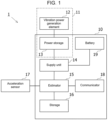
- the motor monitoring sensor 1 includes a housing 10, a vibration-powered generator 11, a supply unit 14, an estimator 15, a storage 16, an acceleration sensor 17, a communicator 18, and a battery 19.
- the vibration-powered generator 11 includes a vibration power generation element 12 and a storage battery 13.
- the vibration power generation element 12 and the acceleration sensor 17 are located outside the housing 10.
- the storage battery 13, the supply unit 14, the estimator 15, the storage 16, the communicator 18, and the battery 19 are accommodated in the housing 10.
- the motor monitoring sensor 1 is used with, for example, the acceleration sensor 17 and the vibration power generation element 12 placed on a motor body 21 as shown in FIG. 2 .
- the vibration power generation element 12 generates power with the vibration of a motor 2 being driven.
- the power generated by the vibration power generation element 12 is supplied to, for example, the estimator 15, the acceleration sensor 17, and the communicator 18.
- the acceleration sensor 17 detects the vibration of the motor 2.
- the estimator 15 uses a detection value indicating the vibration of the motor 2 detected by the acceleration sensor 17 to generate state information indicating the state of the motor 2.
- the communicator 18 transmits the state information generated by the estimator 15 to a host device.
- the vibration power generation element 12 uses the vibration of the motor 2 to generate power to drive the estimator 15, the acceleration sensor 17, and the communicator 18.
- the motor monitoring sensor 1 is drivable without using any battery or external power supply, eliminating the work-hours for battery replacement or electrical work.
- the motor monitoring sensor 1 can continuously monitor the motor 2 at a lower cost.
- FIG. 1 is a block diagram of a motor monitoring sensor 1 according to an embodiment.
- FIG. 2 is a diagram of the motor monitoring sensor 1 according to the embodiment, showing an example use of the motor monitoring sensor 1.
- the position of a motor shaft 22 in the motor body 21 is indicated by dotted lines.
- the motor monitoring sensor 1 detects the vibration of the motor 2 and diagnoses the state of the motor 2 based on the detected vibration.
- the motor 2 monitored by the motor monitoring sensor 1 is, for example, an electric motor that drives various devices in a building.
- the motor 2 is used in, for example, an in-house power generation system and a power receiving and transforming facility.
- the motor 2 is used in, for example, a hot and cold water generator, an absorption refrigerator, and a centrifugal chiller.
- the motor 2 is used to power, for example, a water or sewage pump, an elevator, an automatic door, and a shutter.
- the motor 2 may also be used in, for example, an air conditioner and a lighting apparatus.
- the vibration-powered generator 11 includes the vibration power generation element 12 that generates power with vibration and the storage battery 13 that stores the power generated by the vibration power generation element 12.
- Examples of the storage battery 13 include a capacitor and a secondary battery.
- the battery 19 is, for example, a primary battery. Examples of the battery 19 include a button battery and a dry cell.
- the supply unit 14 supplies power supplied from the vibration-powered generator 11 and the battery 19 to the estimator 15, the acceleration sensor 17, and the communicator 18. For example, when power supplied from the vibration-powered generator 11 is sufficient for consumption by the estimator 15, the acceleration sensor 17, and the communicator 18, the supply unit 14 supplies the power from the vibration-powered generator 11 to the estimator 15, the acceleration sensor 17, and the communicator 18, and reduces (or prohibits) power supply from the battery 19. For example, when power supplied from the vibration-powered generator 11 is insufficient for consumption by the estimator 15, the acceleration sensor 17, and the communicator 18, the supply unit 14 also supplies, in addition to the power from the vibration-powered generator 11, power supplied from the battery 19 to the estimator 15, the acceleration sensor 17, and the communicator 18.
- the acceleration sensor 17 detects acceleration.
- the acceleration sensor 17 may be a two-axis sensor or a three-axis sensor.
- the acceleration sensor 17 is attached to the motor 2 and detects the vibration of the motor 2.
- the acceleration sensor 17 outputs, to the estimator 15, a detection value indicating the detected vibration of the motor 2.
- the acceleration sensor 17 may be placed above the motor shaft 22 of the motor 2.
- the acceleration sensor 17 may be placed in, for example, an area A1 or A2 in FIG. 2 .
- the estimator 15 is, for example, a processor.
- the estimator 15 executes a predetermined program stored in the storage 16 to perform intended processing.
- the storage 16 is, for example, an erasable programmable read-only memory (EPROM), a solid-state drive (SSD), or a hard disk drive (HDD).
- EPROM erasable programmable read-only memory
- SSD solid-state drive
- HDD hard disk drive
- the estimator 15 stores the detection value received from the acceleration sensor 17 into the storage 16 together with the time at which the detection value is received from the acceleration sensor 17.
- the estimator 15 generates state information indicating the state of the motor 2 based on the time-series detection values stored in the storage 16.
- the state information includes, for example, the effective value (root-mean-square, or RMS, value) of the vibration velocity of the motor 2.
- the estimator 15 determines the RMS value of the vibration velocity of the motor 2 using, for example, Formula 1 or Formula 2 below.
- Formula 1 Formula 1 or Formula 2 below.
- v(t) is the vibration velocity as a function of time
- T is the sampling time. The sampling time is longer than the cycle of a main vibration component of the vibration velocity v(t).
- the values a 1 , a 2 , a 3 , ..., and a n are the RMS values of the vibration acceleration.
- the values f 1 , f 2 , f 3 , ..., and f n are the RMS values of the vibration frequency.
- v rms is the RMS value of the vibration velocity.
- the state of the motor 2 can be indicated with, for example, the RMS value v rms of the vibration velocity.
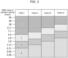
- FIG. 3 is a diagram showing an example correspondence between the RMS value of the vibration velocity of the motor 2 and the state of the motor 2.
- FIG. 3 shows the value v rms and the state of the motor 2 in class I, class II, class III, or class IV.
- the motor 2 in the class I is an electric motor with a power of less than or equal to 15 kW.
- the motor 2 in the class II is an electric motor with a power of less than or equal to 75 kW.
- An electric motor in the class III is a large electric motor installed on a rigid foundation.
- An electric motor in the class IV is a large electric motor installed on a soft foundation.
- the state of the motor 2 is classified into one of four levels of A, B, C, and D based on the value v rms .
- the level A indicates that the motor 2 is newly installed
- the level B indicates that the motor 2 is operable over a long period
- the level C indicates that the motor 2 is not expected to be operable over a long period
- the level D indicates that the motor 2 is in a severe condition with a possibility to break.
- the state of the motor 2 can be determined based on the value V rms .
- the communicator 18 is a communication module that transmits the state information generated by the estimator 15 to the host device.
- the communicator 18 communicates with the host device using, for example, Wi-Fi (registered trademark), Bluetooth (registered trademark), or LoRa (registered trademark).
- FIGs. 4 and 5 are flowcharts of an example process performed by the motor monitoring sensor 1.
- A indicates a continuation to A in FIG. 5
- B indicates a continuation to B in FIG. 5 .
- the processing shown in FIGs. 4 and 5 is performed repeatedly once vibration power generation is started by the vibration power generation element 12.
- the example process performed by the motor monitoring sensor 1 will now be described with reference to FIGs. 4 and 5 .
- step S1 the estimator 15 determines whether vibration power generation is performed by the vibration power generation element 12. For example, when power generated through the vibration power generation performed by the vibration power generation element 12 is less than or equal to a predetermined threshold, the estimator 15 determines that no vibration power generation is performed. When the vibration power generation is performed, the estimator 15 stores a detection value detected by the acceleration sensor 17 into the storage 16 together with the time of detection. When the vibration power generation is performed (Yes in step S1), the processing advances to step S2. When no vibration power generation is performed (No in step S1), the processing advances to step S8.
- step S2 the estimator 15 determines whether an operation flag is on. In response to the motor 2 determined to be in operation, the estimator 15 sets the operation flag to on. When the operation flag is on (Yes in step S2), the processing advances to step S5. When the operation flag is off (No in step S2), the processing advances to step S3.
- the estimator 15 causes the communicator 18 to transmit state information indicating that the motor 2 is in operation.
- the estimator 15 may add, to the state information, the value v rms calculated using the above Formula 1 or Formula 2 based on time-series information about the detection values stored in the storage 16 and cause the communicator 18 to transmit the state information.
- step S4 the estimator 15 sets the operation flag to on.
- the estimator 15 also sets a nonoperational flag to off.
- the nonoperational flag indicates that the motor 2 is nonoperational.
- the set flags are stored into, for example, the storage 16.
- step S5 the supply unit 14 determines whether power supplied from the vibration power generation element 12 is insufficient to drive the estimator 15, the acceleration sensor 17, and the communicator 18. When the power is insufficient (Yes in step S5), the processing advances to step S6. When the power is sufficient (No in step S5), the processing advances to step S7.
- step S6 the supply unit 14 also supplies power from the battery 19 to the estimator 15, the acceleration sensor 17, and the communicator 18.
- step S7 the supply unit 14 charges the storage battery 13 with excess power supplied from the vibration-powered generator 11.
- step S8 the estimator 15 determines whether the nonoperational flag is on. When the nonoperational flag is on (Yes in step S8), the processing advances to step S1. When the nonoperational flag is off (No in step S8), the processing advances to step S9.
- the estimator 15 causes the communicator 18 to transmit state information indicating that the motor 2 is nonoperational (stopped).
- the estimator 15 may add, to the state information, the value v rms calculated using the above Formula 1 or Formula 2 based on the acceleration obtained from the acceleration sensor 17 and cause the communicator 18 to transmit the state information.
- step S10 the estimator 15 sets the nonoperational flag to on.
- the estimator 15 also sets the operation flag to off.
- the set flags are stored into, for example, the storage 16.
- the motor monitoring sensor 1 includes the vibration-powered generator 11 that generates power with the vibration of the motor 2.
- the estimator 15, the acceleration sensor 17, and the communicator 18 are driven by power supplied from the vibration-powered generator 11.
- the motor monitoring sensor 1 thus allows the estimator 15, the acceleration sensor 17, and the communicator 18 to be driven without the battery 19. This reduces the frequency of replacement of the battery 19 in the motor monitoring sensor 1, and thus allows the motor monitoring sensor 1 to be used continuously for monitoring the motor 2 at a lower cost.
- the motor monitoring sensor 1 including the estimator 15 consumes more power.
- the battery is to be replaced frequently.
- the motor monitoring sensor 1 is driven by power supplied from the vibration-powered generator 11 that generates power with the vibration of the motor 2, thus reducing the frequency of battery replacement. With power supplied from the vibration-powered generator 11 sufficient to drive the motor monitoring sensor 1, the motor monitoring sensor 1 may eliminate the battery 19.
- the motor monitoring sensor 1 includes the storage battery 13 that stores power generated by the vibration power generation element 12. Power generated by the vibration power generation element 12 is dependent on the vibration of the motor 2, and thus may not be supplied stably to drive the estimator 15, the acceleration sensor 17, and the communicator 18.
- the storage battery 13 stores excess power generated by the vibration power generation element 12. The power stored in the storage battery 13 is used to supplement any insufficiency of power generated by the vibration power generation element 12. This allows the motor monitoring sensor 1 to be driven more stably.
- the motor monitoring sensor 1 also includes the battery 19 in addition to the vibration-powered generator 11. As described above, power generated by the vibration power generation element 12 is dependent on the vibration of the motor 2 and thus may not be supplied stably.
- the motor monitoring sensor 1 including the battery 19 can use power supplied from the battery 19 to supplement any insufficiency of power supplied from the vibration-powered generator 11. This allows the motor monitoring sensor 1 to be driven more stably.
- the motor monitoring sensor 1 causes the communicator 18 to provide a notification of the motor 2 being nonoperational in response to the power generated by the vibration power generation element 12 being less than or equal to the predetermined threshold.
- the estimator 15 causes the communicator 18 to transmit the state information indicating that the motor 2 is nonoperational.
- the structure according to the present embodiment can provide a notification of the motor 2 being nonoperational when the acceleration sensor 17 has a failure or when power generated by the vibration power generation element 12 is insufficient to drive the acceleration sensor 17.
- the estimator 15 calculates the value v rms , which indicates the state of the motor 2, using the above Formula 1 or Formula 2 based on time-series data about the detection values from the acceleration sensor 17 stored in the storage 16. The estimator 15 then adds the calculated v rms to the state information and transmits the state information to the host device. As described with reference to FIG. 3 , the value v rms indicates the state of the motor 2.
- the motor monitoring sensor 1 according to the embodiment can provide, to the host device, information indicating that the motor 2 is operable over a long period or that the motor 2 is to be replaced.
- the estimator 15 may notify the host device of an index value indicating the state of the motor 2 indicated by the value v rms .
- the index value indicating the state of the motor 2 may be one of four levels of index values, which are, for example, an index value indicating that the motor 2 is newly installed, an index value indicating that the motor 2 is operable over a long period, an index value indicating that the motor 2 is not expected to be operable over a long period, and an index value indicating that the motor 2 is in a severe condition with a possibility to break, as described with reference to FIG. 3 .
- the index value indicating that the motor 2 is newly installed, the index value indicating that the motor 2 is operable over a long period, the index value indicating that the motor 2 is not expected to be operable over a long period, and the index value indicating that the motor 2 is in a severe condition with a possibility to break are examples of three or more levels of index values.
- the state of the motor 2 may be indicated using one of two levels of index values, which are, for example, an index value indicating that the motor 2 is continuously operable and an index value indicating that the motor 2 is recommended to be replaced.
- the state of the motor 2 being continuously operable may be either the state of the motor 2 being newly established or the state of the motor 2 being operable over a long period described with reference to FIG. 3 .
- the state of the motor 2 recommended to be replaced may be either the state of the motor 2 not expected to be operable over a long period or the state of the motor 2 being in a severe condition with a possibility to break described with reference to FIG. 3 .
- the index value indicating that the motor 2 is continuously operable is an example index value indicating normality.
- the index value indicating that the motor 2 is recommended to be replaced is an example index value indicating abnormality.
- the estimator 15 provides a notification of the motor 2 being nonoperational when no vibration power generation is performed by the vibration power generation element 12.
- the motor 2 may not be constantly driven.
- the motor 2 may be stopped as planned for specific periods.
- the storage 16 may prestore information indicating time slots in which the motor 2 is stopped.
- the estimator 15 may stop providing a notification of the motor 2 being nonoperational when no vibration power generation is performed within the time slots prestored in the storage 16.
- the estimator 15 may provide a notification of the motor 2 being nonoperational when no vibration power generation is performed by the vibration power generation element 12 in a time slot different from the time slots stored in the storage 16.
- the motor monitoring sensor 1 includes the battery 19. With power generated through the vibration power generation performed by the vibration-powered generator 11 sufficient to drive the motor monitoring sensor 1, the motor monitoring sensor 1 may eliminate the battery 19.
- a motor monitoring sensor (1) comprising:
Landscapes
- Engineering & Computer Science (AREA)
- Power Engineering (AREA)
- Microelectronics & Electronic Packaging (AREA)
- Physics & Mathematics (AREA)
- General Physics & Mathematics (AREA)
- Measurement Of Mechanical Vibrations Or Ultrasonic Waves (AREA)
- Testing Of Devices, Machine Parts, Or Other Structures Thereof (AREA)
- Testing And Monitoring For Control Systems (AREA)
Abstract
Description
- The present invention relates to a motor monitoring sensor.
- Sensors are used to monitor motors that drive devices. For example, Non-Patent Literature 1 describes a battery-powered sensor. For example, Non-Patent Literature 2 describes a sensor that operates with power received from an external power supply.
- Non-Patent Literature 1: WISE-2410 LoRaWAN Wireless Condition Monitoring Sensor [Online]. Advantec Co., Ltd., [retrieved on 2022-08-07]. Retrieved from the Internet: < URL: https://www.advantech.co.jp/products/78b36b30-8dc1-44b3-91a3-01337cc09b11/wise-2410/mod_25018dc7-355c-40b4-bf9b-c93f6c73f1a0>
- Non-Patent Literature 2: iQ Monozukuri Rotating Machine Vibration Diagnosis Introduction of Operation Check Equipment [Online]. Mitsubishi Electric Corporation, February 2019 [retrieved on 2022-08-07], Retrieved from the Internet: < URL: https://www.mitsubishielectric.co.jp/fa/document/technews/sol/iqmonozukuri/bcn-e2113-0033/bcne21130033f.pdf >
- When, for example, a motor has a failure and stops suddenly during operation, a belt attached to the rotational shaft of the motor may be entangled or a secondary device may rotate without contacting the motor. This may possibly cause failures in other devices connected to the motor. The state of the motor is thus to be continuously monitored with a sensor. However, continuous monitoring of a motor with a battery-powered sensor causes battery replacement with an additional cost. Monitoring of a motor with a sensor that receives power from an external power supply causes electrical work for installing the sensor. In other words, monitoring of a motor either with a battery-powered sensor or a sensor that receives power from an external power supply increases the operating cost of the motor.
- A technique according to an aspect of the disclosure is directed to a motor monitoring sensor that is continuously operable at a lower cost.
- A technique according to an aspect of the disclosure may be a motor monitoring sensor described below. The motor monitoring sensor includes an acceleration sensor attachable to a motor to be monitored to detect vibration of the motor, a processor that generates state information indicating a state of the motor based on a detection value indicating the vibration of the motor detected by the acceleration sensor, a transmitter that transmits the generated state information to a host device, and a vibration-powered generator attachable to the motor to generate power with the vibration of the motor and supply the generated power to the acceleration sensor, the processor, and the transmitter.
- The motor monitoring sensor includes the vibration-powered generator that generates power with the vibration of the motor to be monitored. In the motor monitoring sensor, the processor, the acceleration sensor, and the communicator are driven by power supplied from the vibration-powered generator. The motor monitoring sensor is thus drivable without a battery. The motor monitoring sensor with this structure reduces the operating cost associated with battery replacement and is thus continuously operable at a lower cost.
- The motor monitoring sensor may also have the features described below. The vibration-powered generator includes a vibration power generation element that generates power with the vibration of the motor and a power storage that stores the power generated by the vibration power generation element. The motor monitoring sensor may supply the power stored in the power storage to the processor and the transmitter. Power generated by the vibration power generation element is dependent on the vibration of the motor, and thus may not be supplied stably to drive the processor, the acceleration sensor, and the communicator. The power storage stores excess power generated by the vibration power generation element. The power stored in the power storage is used to supplement any insufficiency of power generated by the vibration power generation element. This allows the motor monitoring sensor to be driven more stably.
- The motor monitoring sensor may further include a battery. The motor monitoring sensor may supply power from the battery to the processor and the transmitter in response to the power generated by the vibration-powered generator being insufficient to drive the processor and the transmitter. As described above, power generated by the vibration-powered generator is dependent on the vibration of the motor, and thus may not be supplied stably. The motor monitoring sensor further including the battery also uses power supplied from the battery to supplement any insufficiency of power supplied from the vibration-powered generator, and can thus monitor the motor more stably.
- The motor monitoring sensor may also have the features described below. The processor adds, to the state information, information indicating that the motor is stopped in response to the power supplied from the vibration-powered generator being less than or equal to a predetermined threshold. The vibration-powered generator generates power with the vibration of the motor, and can thus detect the motor being stopped in response to the amount of power generated by the vibration-powered generator being less than or equal to the predetermined threshold. The motor monitoring sensor with these features can provide, to the host device, a notification of the motor being stopped when, for example, the acceleration sensor has a failure or power is insufficient to drive the acceleration sensor.
- The motor monitoring sensor may also have the features described below. The motor monitoring sensor further includes a storage that stores a time slot in which the motor is stopped. The processor adds information indicating a failure of the motor to the state information in response to the motor detected as being stopped at a time different from the time slot. The motor may not be constantly driven and may be stopped as planned. The storage prestores the time slots in which the motor is stopped. The motor monitoring sensor reduces notifications of the motor being stopped when the motor is detected as being stopped within these time slots.
- The state information may be generated based on time-series data about the detection value detected by the acceleration sensor. The processor may determine a failure value indicating a degree of failure of the motor based on the detection value and add the failure value to the state information. The failure value may include three or more levels of index values each corresponding to the degree of failure of the motor, or may include an index value indicating normality of the motor or an index value indicating abnormality of the motor.
- The motor monitoring sensor according to the above aspects of the disclosure is continuously operable at a lower cost.
-
-
FIG. 1 is a block diagram of a motor monitoring sensor according to an embodiment. -
FIG. 2 is a diagram of the motor monitoring sensor according to the embodiment, showing an example use of the motor monitoring sensor. -
FIG. 3 is a diagram showing an example correspondence between the root-mean-square (RMS) value of the vibration velocity of a motor and the state of the motor. -
FIG. 4 is a first flowchart of an example process performed by the motor monitoring sensor. -
FIG. 5 is a second flowchart of the example process performed by the motor monitoring sensor. - An example use of the present invention will now be described with reference to the drawings. The present invention is applicable to, for example, an example
motor monitoring sensor 1 shown inFIG. 1 . Themotor monitoring sensor 1 includes ahousing 10, a vibration-poweredgenerator 11, asupply unit 14, anestimator 15, astorage 16, anacceleration sensor 17, acommunicator 18, and abattery 19. The vibration-poweredgenerator 11 includes a vibrationpower generation element 12 and astorage battery 13. The vibrationpower generation element 12 and theacceleration sensor 17 are located outside thehousing 10. Thestorage battery 13, thesupply unit 14, theestimator 15, thestorage 16, thecommunicator 18, and thebattery 19 are accommodated in thehousing 10. - The
motor monitoring sensor 1 is used with, for example, theacceleration sensor 17 and the vibrationpower generation element 12 placed on amotor body 21 as shown inFIG. 2 . The vibrationpower generation element 12 generates power with the vibration of a motor 2 being driven. The power generated by the vibrationpower generation element 12 is supplied to, for example, theestimator 15, theacceleration sensor 17, and thecommunicator 18. Theacceleration sensor 17 detects the vibration of the motor 2. Theestimator 15 uses a detection value indicating the vibration of the motor 2 detected by theacceleration sensor 17 to generate state information indicating the state of the motor 2. Thecommunicator 18 transmits the state information generated by theestimator 15 to a host device. - In the
motor monitoring sensor 1 with this structure, the vibrationpower generation element 12 uses the vibration of the motor 2 to generate power to drive theestimator 15, theacceleration sensor 17, and thecommunicator 18. Themotor monitoring sensor 1 is drivable without using any battery or external power supply, eliminating the work-hours for battery replacement or electrical work. Themotor monitoring sensor 1 can continuously monitor the motor 2 at a lower cost. - The
motor monitoring sensor 1 will now be further described with reference to the drawings.FIG. 1 is a block diagram of amotor monitoring sensor 1 according to an embodiment.FIG. 2 is a diagram of themotor monitoring sensor 1 according to the embodiment, showing an example use of themotor monitoring sensor 1. InFIG. 2 , the position of amotor shaft 22 in themotor body 21 is indicated by dotted lines. Themotor monitoring sensor 1 detects the vibration of the motor 2 and diagnoses the state of the motor 2 based on the detected vibration. - The motor 2 monitored by the
motor monitoring sensor 1 is, for example, an electric motor that drives various devices in a building. The motor 2 is used in, for example, an in-house power generation system and a power receiving and transforming facility. The motor 2 is used in, for example, a hot and cold water generator, an absorption refrigerator, and a centrifugal chiller. The motor 2 is used to power, for example, a water or sewage pump, an elevator, an automatic door, and a shutter. The motor 2 may also be used in, for example, an air conditioner and a lighting apparatus. - The vibration-powered
generator 11 includes the vibrationpower generation element 12 that generates power with vibration and thestorage battery 13 that stores the power generated by the vibrationpower generation element 12. Examples of thestorage battery 13 include a capacitor and a secondary battery. Thebattery 19 is, for example, a primary battery. Examples of thebattery 19 include a button battery and a dry cell. - The
supply unit 14 supplies power supplied from the vibration-poweredgenerator 11 and thebattery 19 to theestimator 15, theacceleration sensor 17, and thecommunicator 18. For example, when power supplied from the vibration-poweredgenerator 11 is sufficient for consumption by theestimator 15, theacceleration sensor 17, and thecommunicator 18, thesupply unit 14 supplies the power from the vibration-poweredgenerator 11 to theestimator 15, theacceleration sensor 17, and thecommunicator 18, and reduces (or prohibits) power supply from thebattery 19. For example, when power supplied from the vibration-poweredgenerator 11 is insufficient for consumption by theestimator 15, theacceleration sensor 17, and thecommunicator 18, thesupply unit 14 also supplies, in addition to the power from the vibration-poweredgenerator 11, power supplied from thebattery 19 to theestimator 15, theacceleration sensor 17, and thecommunicator 18. - The
acceleration sensor 17 detects acceleration. Theacceleration sensor 17 may be a two-axis sensor or a three-axis sensor. Theacceleration sensor 17 is attached to the motor 2 and detects the vibration of the motor 2. Theacceleration sensor 17 outputs, to theestimator 15, a detection value indicating the detected vibration of the motor 2. Theacceleration sensor 17 may be placed above themotor shaft 22 of the motor 2. Theacceleration sensor 17 may be placed in, for example, an area A1 or A2 inFIG. 2 . - The
estimator 15 is, for example, a processor. Theestimator 15 executes a predetermined program stored in thestorage 16 to perform intended processing. Thestorage 16 is, for example, an erasable programmable read-only memory (EPROM), a solid-state drive (SSD), or a hard disk drive (HDD). - The
estimator 15 stores the detection value received from theacceleration sensor 17 into thestorage 16 together with the time at which the detection value is received from theacceleration sensor 17. Theestimator 15 generates state information indicating the state of the motor 2 based on the time-series detection values stored in thestorage 16. The state information includes, for example, the effective value (root-mean-square, or RMS, value) of the vibration velocity of the motor 2. - The
estimator 15 determines the RMS value of the vibration velocity of the motor 2 using, for example,Formula 1 or Formula 2 below.
[Math 1]

- In
Formula 1, v(t) is the vibration velocity as a function of time, and T is the sampling time. The sampling time is longer than the cycle of a main vibration component of the vibration velocity v(t). In Formula 2, the values a1, a2, a3, ..., and an are the RMS values of the vibration acceleration. The values f1, f2, f3, ..., and fn are the RMS values of the vibration frequency. InFormulas 1 and 2, vrms is the RMS value of the vibration velocity. - The state of the motor 2 can be indicated with, for example, the RMS value vrms of the vibration velocity.
FIG. 3 is a diagram showing an example correspondence between the RMS value of the vibration velocity of the motor 2 and the state of the motor 2.FIG. 3 shows the value vrms and the state of the motor 2 in class I, class II, class III, or class IV. The motor 2 in the class I is an electric motor with a power of less than or equal to 15 kW. The motor 2 in the class II is an electric motor with a power of less than or equal to 75 kW. An electric motor in the class III is a large electric motor installed on a rigid foundation. An electric motor in the class IV is a large electric motor installed on a soft foundation. - In
FIG. 3 , the state of the motor 2 is classified into one of four levels of A, B, C, and D based on the value vrms. For example, the level A indicates that the motor 2 is newly installed, the level B indicates that the motor 2 is operable over a long period, the level C indicates that the motor 2 is not expected to be operable over a long period, and the level D indicates that the motor 2 is in a severe condition with a possibility to break. In this manner, the state of the motor 2 can be determined based on the value Vrms. - The
communicator 18 is a communication module that transmits the state information generated by theestimator 15 to the host device. Thecommunicator 18 communicates with the host device using, for example, Wi-Fi (registered trademark), Bluetooth (registered trademark), or LoRa (registered trademark). -
FIGs. 4 and5 are flowcharts of an example process performed by themotor monitoring sensor 1. InFIG. 4 , A indicates a continuation to A inFIG. 5 , and B indicates a continuation to B inFIG. 5 . The processing shown inFIGs. 4 and5 is performed repeatedly once vibration power generation is started by the vibrationpower generation element 12. The example process performed by themotor monitoring sensor 1 will now be described with reference toFIGs. 4 and5 . - In step S1, the
estimator 15 determines whether vibration power generation is performed by the vibrationpower generation element 12. For example, when power generated through the vibration power generation performed by the vibrationpower generation element 12 is less than or equal to a predetermined threshold, theestimator 15 determines that no vibration power generation is performed. When the vibration power generation is performed, theestimator 15 stores a detection value detected by theacceleration sensor 17 into thestorage 16 together with the time of detection. When the vibration power generation is performed (Yes in step S1), the processing advances to step S2. When no vibration power generation is performed (No in step S1), the processing advances to step S8. - In step S2, the
estimator 15 determines whether an operation flag is on. In response to the motor 2 determined to be in operation, theestimator 15 sets the operation flag to on. When the operation flag is on (Yes in step S2), the processing advances to step S5. When the operation flag is off (No in step S2), the processing advances to step S3. - In step S3, the
estimator 15 causes thecommunicator 18 to transmit state information indicating that the motor 2 is in operation. For example, theestimator 15 may add, to the state information, the value vrms calculated using theabove Formula 1 or Formula 2 based on time-series information about the detection values stored in thestorage 16 and cause thecommunicator 18 to transmit the state information. - In step S4, the
estimator 15 sets the operation flag to on. Theestimator 15 also sets a nonoperational flag to off. The nonoperational flag indicates that the motor 2 is nonoperational. The set flags are stored into, for example, thestorage 16. - In step S5, the
supply unit 14 determines whether power supplied from the vibrationpower generation element 12 is insufficient to drive theestimator 15, theacceleration sensor 17, and thecommunicator 18. When the power is insufficient (Yes in step S5), the processing advances to step S6. When the power is sufficient (No in step S5), the processing advances to step S7. - In step S6, the
supply unit 14 also supplies power from thebattery 19 to theestimator 15, theacceleration sensor 17, and thecommunicator 18. In step S7, thesupply unit 14 charges thestorage battery 13 with excess power supplied from the vibration-poweredgenerator 11. When the processing in step S6 or S7 is complete, the processing advances to step S1. - In step S8, the
estimator 15 determines whether the nonoperational flag is on. When the nonoperational flag is on (Yes in step S8), the processing advances to step S1. When the nonoperational flag is off (No in step S8), the processing advances to step S9. - In step S9, the
estimator 15 causes thecommunicator 18 to transmit state information indicating that the motor 2 is nonoperational (stopped). For example, theestimator 15 may add, to the state information, the value vrms calculated using theabove Formula 1 or Formula 2 based on the acceleration obtained from theacceleration sensor 17 and cause thecommunicator 18 to transmit the state information. - In step S10, the
estimator 15 sets the nonoperational flag to on. Theestimator 15 also sets the operation flag to off. The set flags are stored into, for example, thestorage 16. - In the embodiment, the
motor monitoring sensor 1 includes the vibration-poweredgenerator 11 that generates power with the vibration of the motor 2. In themotor monitoring sensor 1, theestimator 15, theacceleration sensor 17, and thecommunicator 18 are driven by power supplied from the vibration-poweredgenerator 11. Themotor monitoring sensor 1 thus allows theestimator 15, theacceleration sensor 17, and thecommunicator 18 to be driven without thebattery 19. This reduces the frequency of replacement of thebattery 19 in themotor monitoring sensor 1, and thus allows themotor monitoring sensor 1 to be used continuously for monitoring the motor 2 at a lower cost. - The
motor monitoring sensor 1 including theestimator 15 consumes more power. For a motor monitoring sensor that does not include the vibration-poweredgenerator 11 and is driven by power supplied from a battery, the battery is to be replaced frequently. In the present embodiment, themotor monitoring sensor 1 is driven by power supplied from the vibration-poweredgenerator 11 that generates power with the vibration of the motor 2, thus reducing the frequency of battery replacement. With power supplied from the vibration-poweredgenerator 11 sufficient to drive themotor monitoring sensor 1, themotor monitoring sensor 1 may eliminate thebattery 19. - The
motor monitoring sensor 1 includes thestorage battery 13 that stores power generated by the vibrationpower generation element 12. Power generated by the vibrationpower generation element 12 is dependent on the vibration of the motor 2, and thus may not be supplied stably to drive theestimator 15, theacceleration sensor 17, and thecommunicator 18. Thestorage battery 13 stores excess power generated by the vibrationpower generation element 12. The power stored in thestorage battery 13 is used to supplement any insufficiency of power generated by the vibrationpower generation element 12. This allows themotor monitoring sensor 1 to be driven more stably. - In the embodiment, the
motor monitoring sensor 1 also includes thebattery 19 in addition to the vibration-poweredgenerator 11. As described above, power generated by the vibrationpower generation element 12 is dependent on the vibration of the motor 2 and thus may not be supplied stably. In the present embodiment, themotor monitoring sensor 1 including thebattery 19 can use power supplied from thebattery 19 to supplement any insufficiency of power supplied from the vibration-poweredgenerator 11. This allows themotor monitoring sensor 1 to be driven more stably. - In the embodiment, the
motor monitoring sensor 1 causes thecommunicator 18 to provide a notification of the motor 2 being nonoperational in response to the power generated by the vibrationpower generation element 12 being less than or equal to the predetermined threshold. When power generated by the vibrationpower generation element 12 is less than or equal to the predetermined threshold, theestimator 15 causes thecommunicator 18 to transmit the state information indicating that the motor 2 is nonoperational. The structure according to the present embodiment can provide a notification of the motor 2 being nonoperational when theacceleration sensor 17 has a failure or when power generated by the vibrationpower generation element 12 is insufficient to drive theacceleration sensor 17. - In the embodiment, the
estimator 15 calculates the value vrms, which indicates the state of the motor 2, using theabove Formula 1 or Formula 2 based on time-series data about the detection values from theacceleration sensor 17 stored in thestorage 16. Theestimator 15 then adds the calculated vrms to the state information and transmits the state information to the host device. As described with reference toFIG. 3 , the value vrms indicates the state of the motor 2. In other words, themotor monitoring sensor 1 according to the embodiment can provide, to the host device, information indicating that the motor 2 is operable over a long period or that the motor 2 is to be replaced. - Instead of notifying the value vrms, the
estimator 15 may notify the host device of an index value indicating the state of the motor 2 indicated by the value vrms. The index value indicating the state of the motor 2 may be one of four levels of index values, which are, for example, an index value indicating that the motor 2 is newly installed, an index value indicating that the motor 2 is operable over a long period, an index value indicating that the motor 2 is not expected to be operable over a long period, and an index value indicating that the motor 2 is in a severe condition with a possibility to break, as described with reference toFIG. 3 . The index value indicating that the motor 2 is newly installed, the index value indicating that the motor 2 is operable over a long period, the index value indicating that the motor 2 is not expected to be operable over a long period, and the index value indicating that the motor 2 is in a severe condition with a possibility to break are examples of three or more levels of index values. - The state of the motor 2 may be indicated using one of two levels of index values, which are, for example, an index value indicating that the motor 2 is continuously operable and an index value indicating that the motor 2 is recommended to be replaced. The state of the motor 2 being continuously operable may be either the state of the motor 2 being newly established or the state of the motor 2 being operable over a long period described with reference to
FIG. 3 . The state of the motor 2 recommended to be replaced may be either the state of the motor 2 not expected to be operable over a long period or the state of the motor 2 being in a severe condition with a possibility to break described with reference toFIG. 3 . The index value indicating that the motor 2 is continuously operable is an example index value indicating normality. The index value indicating that the motor 2 is recommended to be replaced is an example index value indicating abnormality. - In the embodiment, the
estimator 15 provides a notification of the motor 2 being nonoperational when no vibration power generation is performed by the vibrationpower generation element 12. However, the motor 2 may not be constantly driven. For example, the motor 2 may be stopped as planned for specific periods. Thestorage 16 may prestore information indicating time slots in which the motor 2 is stopped. Theestimator 15 may stop providing a notification of the motor 2 being nonoperational when no vibration power generation is performed within the time slots prestored in thestorage 16. In other words, theestimator 15 may provide a notification of the motor 2 being nonoperational when no vibration power generation is performed by the vibrationpower generation element 12 in a time slot different from the time slots stored in thestorage 16. - In the embodiment, the
motor monitoring sensor 1 includes thebattery 19. With power generated through the vibration power generation performed by the vibration-poweredgenerator 11 sufficient to drive themotor monitoring sensor 1, themotor monitoring sensor 1 may eliminate thebattery 19. - The embodiment and the modifications described above may each be combined together.
- A motor monitoring sensor (1), comprising:
- an acceleration sensor (17) attachable to a motor (2) to be monitored to detect vibration of the motor (2);
- a processor (15) configured to generate state information indicating a state of the motor (2) based on a detection value indicating the vibration of the motor (2) detected by the acceleration sensor (17);
- a transmitter (18) configured to transmit the generated state information to a host device; and
- a vibration-powered generator (11) attachable to the motor (2) to generate power with the vibration of the motor (2) and supply the generated power to the acceleration sensor (17), the processor (15), and the transmitter (18).
Claims (9)
- A motor monitoring sensor (1), comprising:an acceleration sensor (17) attachable to a motor (2) to be monitored to detect vibration of the motor (2);a processor (15) configured to generate state information indicating a state of the motor (2) based on a detection value indicating the vibration of the motor (2) detected by the acceleration sensor (17);a transmitter (18) configured to transmit the generated state information to a host device; anda vibration-powered generator (11) attachable to the motor (2) to generate power with the vibration of the motor (2) and supply the generated power to the acceleration sensor (17), the processor (15), and the transmitter (18).
- The motor monitoring sensor (1) according to claim 1, whereinthe vibration-powered generator (11) includes a vibration power generation element (12) configured to generate power with the vibration of the motor (2) and a power storage (13) configured to store the power generated by the vibration power generation element (12), andthe vibration-powered generator (11) supplies the power stored in the power storage (13) to the processor (15) and the transmitter (18).
- The motor monitoring sensor (1) according to claim 1 or 2, further comprising:a battery (19),wherein the motor monitoring sensor (1) supplies power from the battery (19) to the processor (15) and the transmitter (18) in response to the power generated by the vibration-powered generator (11) being insufficient to drive the processor (15) and the transmitter (18).
- The motor monitoring sensor (1) according to any one of claims 1 to 3,
wherein
the processor (15) adds, to the state information, information indicating that the motor (2) is stopped in response to the power supplied from the vibration-powered generator (11) being less than or equal to a predetermined threshold. - The motor monitoring sensor (1) according to claim 4, further comprising:a storage (16) configured to store a time slot in which the motor (2) is stopped,wherein the processor (15) adds information indicating a failure of the motor (2) to the state information in response to the motor (2) detected as being stopped at a time different from the time slot.
- The motor monitoring sensor (1) according to any one of claims 1 to 5,
wherein
the processor (15) generates the state information based on time-series data about the detection value detected by the acceleration sensor (17). - The motor monitoring sensor (1) according to any one of claims 1 to 6,
wherein
the processor (15) determines a failure value indicating a degree of failure of the motor (2) based on the detection value and adds the failure value to the state information. - The motor monitoring sensor (1) according to claim 7, wherein
the failure value includes three or more levels of index values each corresponding to the degree of failure of the motor (2). - The motor monitoring sensor (1) according to claim 7 or 8, wherein
the failure value includes an index value indicating normality of the motor (2) or an index value indicating abnormality of the motor (2).
Applications Claiming Priority (1)
| Application Number | Priority Date | Filing Date | Title |
|---|---|---|---|
| JP2022145911A JP2024041225A (en) | 2022-09-14 | 2022-09-14 | motor monitoring sensor |
Publications (2)
| Publication Number | Publication Date |
|---|---|
| EP4339565A1 true EP4339565A1 (en) | 2024-03-20 |
| EP4339565B1 EP4339565B1 (en) | 2026-06-10 |
Family
ID=87889255
Family Applications (1)
| Application Number | Title | Priority Date | Filing Date |
|---|---|---|---|
| EP23194426.5A Active EP4339565B1 (en) | 2022-09-14 | 2023-08-31 | Motor monitoring sensor |
Country Status (3)
| Country | Link |
|---|---|
| US (1) | US20240088756A1 (en) |
| EP (1) | EP4339565B1 (en) |
| JP (1) | JP2024041225A (en) |
Citations (6)
| Publication number | Priority date | Publication date | Assignee | Title |
|---|---|---|---|---|
| US20100076714A1 (en) * | 2008-09-25 | 2010-03-25 | Rockwell Automation Technologies, Inc. | Maximum information capture from energy constrained sensor nodes |
| US20120041695A1 (en) * | 2010-08-16 | 2012-02-16 | Csi Technology, Inc. | Integrated vibration measurement and analysis system |
| US20170151964A1 (en) * | 2013-04-30 | 2017-06-01 | Korea Railroad Research Institute | Energy harvester and wireless sensor device having energy harvester |
| US20190136861A1 (en) * | 2017-09-25 | 2019-05-09 | Fluid Handling Llc. | Converting mechanical energy from vibration into electrical energy to power a circuit board for conidtion monitoring of rotating machinery |
| US20200287479A1 (en) * | 2019-03-05 | 2020-09-10 | Case Western Reserve University | Self-powering wireless device and method |
| US20210123835A1 (en) * | 2019-10-28 | 2021-04-29 | Everactive, Inc. | Machine health monitoring |
Family Cites Families (3)
| Publication number | Priority date | Publication date | Assignee | Title |
|---|---|---|---|---|
| JP5609817B2 (en) * | 2011-08-11 | 2014-10-22 | オムロン株式会社 | Wireless sensor module, measurement data processing method, program, and recording medium |
| JP2017181307A (en) * | 2016-03-30 | 2017-10-05 | 住友重機械工業株式会社 | Failure diagnostic device of gear motor |
| JP6979477B2 (en) * | 2020-03-10 | 2021-12-15 | エヌ・ティ・ティ・アドバンステクノロジ株式会社 | Status determination device, status determination method and computer program |
-
2022
- 2022-09-14 JP JP2022145911A patent/JP2024041225A/en active Pending
-
2023
- 2023-08-31 EP EP23194426.5A patent/EP4339565B1/en active Active
- 2023-09-01 US US18/459,878 patent/US20240088756A1/en active Pending
Patent Citations (6)
| Publication number | Priority date | Publication date | Assignee | Title |
|---|---|---|---|---|
| US20100076714A1 (en) * | 2008-09-25 | 2010-03-25 | Rockwell Automation Technologies, Inc. | Maximum information capture from energy constrained sensor nodes |
| US20120041695A1 (en) * | 2010-08-16 | 2012-02-16 | Csi Technology, Inc. | Integrated vibration measurement and analysis system |
| US20170151964A1 (en) * | 2013-04-30 | 2017-06-01 | Korea Railroad Research Institute | Energy harvester and wireless sensor device having energy harvester |
| US20190136861A1 (en) * | 2017-09-25 | 2019-05-09 | Fluid Handling Llc. | Converting mechanical energy from vibration into electrical energy to power a circuit board for conidtion monitoring of rotating machinery |
| US20200287479A1 (en) * | 2019-03-05 | 2020-09-10 | Case Western Reserve University | Self-powering wireless device and method |
| US20210123835A1 (en) * | 2019-10-28 | 2021-04-29 | Everactive, Inc. | Machine health monitoring |
Non-Patent Citations (1)
| Title |
|---|
| "iQ Monozukuri Rotating Machine Vibration Diagnosis Introduction of Operation Check Equipment [Online", 7 August 2022, MITSUBISHI ELECTRIC CORPORATION |
Also Published As
| Publication number | Publication date |
|---|---|
| JP2024041225A (en) | 2024-03-27 |
| US20240088756A1 (en) | 2024-03-14 |
| EP4339565B1 (en) | 2026-06-10 |
Similar Documents
| Publication | Publication Date | Title |
|---|---|---|
| EP2998813A1 (en) | Monitoring system and diagnostic device and monitoring terminal thereof | |
| US10895885B2 (en) | Universal remote machinery monitor | |
| JP5910129B2 (en) | Power storage device, power system, and electric vehicle | |
| US9913006B1 (en) | Power-efficient data-load-efficient method of wirelessly monitoring rotating machines | |
| WO2018109677A1 (en) | A condition monitoring device and a method for monitoring an electrical machine | |
| JP5744826B2 (en) | Remote monitoring and control system for generator cars | |
| Kunthong et al. | IoT-based traction motor drive condition monitoring in electric vehicles: Part 1 | |
| US20240088756A1 (en) | Motor monitoring sensor | |
| JPH11178233A (en) | Battery state determination device and battery deterioration alarm device | |
| CN107425785B (en) | Dynamic Motor Drives for Battery-Operated Devices | |
| US11404730B2 (en) | Sensor device and method for the operation thereof | |
| CN215865487U (en) | Vibration monitoring system | |
| CN110578790A (en) | Reducer monitoring device and reducer working system | |
| US10983028B2 (en) | Planetary gear arrangement | |
| JP2019185336A (en) | Monitoring system | |
| JP7331392B2 (en) | Information processing device, information processing system, information processing method, and computer program | |
| CN110805517A (en) | Hydroelectric generating set health assessment method | |
| JP6910325B2 (en) | Explosion-proof equipment power supply circuit and explosion-proof equipment system | |
| CN213422624U (en) | Condition monitoring device for monitoring rotating equipment in industrial plant | |
| CN218563865U (en) | Fault diagnosis device for shipborne pump | |
| CN113555845B (en) | Overspeed protection device and method for flywheel energy storage box and computer readable storage medium | |
| JP2021134673A (en) | Water supply system | |
| JP2015045584A (en) | Vibration signal acquisition device and vibration monitoring system | |
| CN220210274U (en) | Control device of wire rewinding machine and wire rewinding machine | |
| KR20210058411A (en) | Wireless sensing apparatus and sensing method using the same |
Legal Events
| Date | Code | Title | Description |
|---|---|---|---|
| PUAI | Public reference made under article 153(3) epc to a published international application that has entered the european phase |
Free format text: ORIGINAL CODE: 0009012 |
|
| STAA | Information on the status of an ep patent application or granted ep patent |
Free format text: STATUS: REQUEST FOR EXAMINATION WAS MADE |
|
| 17P | Request for examination filed |
Effective date: 20230831 |
|
| AK | Designated contracting states |
Kind code of ref document: A1 Designated state(s): AL AT BE BG CH CY CZ DE DK EE ES FI FR GB GR HR HU IE IS IT LI LT LU LV MC ME MK MT NL NO PL PT RO RS SE SI SK SM TR |
|
| RBV | Designated contracting states (corrected) |
Designated state(s): AL AT BE BG CH CY CZ DE DK EE ES FI FR GB GR HR HU IE IS IT LI LT LU LV MC ME MK MT NL NO PL PT RO RS SE SI SK SM TR |
|
| GRAP | Despatch of communication of intention to grant a patent |
Free format text: ORIGINAL CODE: EPIDOSNIGR1 |
|
| STAA | Information on the status of an ep patent application or granted ep patent |
Free format text: STATUS: GRANT OF PATENT IS INTENDED |
|
| RIC1 | Information provided on ipc code assigned before grant |
Ipc: G01H 1/00 20060101AFI20251216BHEP Ipc: G01R 31/34 20200101ALI20251216BHEP Ipc: H02K 11/20 20160101ALI20251216BHEP Ipc: F03G 7/08 20060101ALI20251216BHEP Ipc: H02N 2/18 20060101ALI20251216BHEP |
|
| INTG | Intention to grant announced |
Effective date: 20260113 |
|
| GRAS | Grant fee paid |
Free format text: ORIGINAL CODE: EPIDOSNIGR3 |
|
| GRAA | (expected) grant |
Free format text: ORIGINAL CODE: 0009210 |
|
| STAA | Information on the status of an ep patent application or granted ep patent |
Free format text: STATUS: THE PATENT HAS BEEN GRANTED |
|
| AK | Designated contracting states |
Kind code of ref document: B1 Designated state(s): AL AT BE BG CH CY CZ DE DK EE ES FI FR GB GR HR HU IE IS IT LI LT LU LV MC ME MK MT NL NO PL PT RO RS SE SI SK SM TR |
|
| REG | Reference to a national code |
Ref country code: CH Ref legal event code: F10 Free format text: ST27 STATUS EVENT CODE: U-0-0-F10-F00 (AS PROVIDED BY THE NATIONAL OFFICE) Effective date: 20260610 Ref country code: GB Ref legal event code: FG4D |
|
| REG | Reference to a national code |
Ref country code: DE Ref legal event code: R096 Ref document number: 602023018271 Country of ref document: DE |
|
| REG | Reference to a national code |
Ref country code: IE Ref legal event code: FG4D |