EP4339532A1 - Cooling system and aircraft cooling system comprising the same - Google Patents
Cooling system and aircraft cooling system comprising the same Download PDFInfo
- Publication number
- EP4339532A1 EP4339532A1 EP23196993.2A EP23196993A EP4339532A1 EP 4339532 A1 EP4339532 A1 EP 4339532A1 EP 23196993 A EP23196993 A EP 23196993A EP 4339532 A1 EP4339532 A1 EP 4339532A1
- Authority
- EP
- European Patent Office
- Prior art keywords
- cooling
- heat load
- fluid
- cooling system
- heat
- Prior art date
- Legal status (The legal status is an assumption and is not a legal conclusion. Google has not performed a legal analysis and makes no representation as to the accuracy of the status listed.)
- Pending
Links
Images


Classifications
-
- F—MECHANICAL ENGINEERING; LIGHTING; HEATING; WEAPONS; BLASTING
- F25—REFRIGERATION OR COOLING; COMBINED HEATING AND REFRIGERATION SYSTEMS; HEAT PUMP SYSTEMS; MANUFACTURE OR STORAGE OF ICE; LIQUEFACTION SOLIDIFICATION OF GASES
- F25B—REFRIGERATION MACHINES, PLANTS OR SYSTEMS; COMBINED HEATING AND REFRIGERATION SYSTEMS; HEAT PUMP SYSTEMS
- F25B1/00—Compression machines, plants or systems with non-reversible cycle
-
- H—ELECTRICITY
- H05—ELECTRIC TECHNIQUES NOT OTHERWISE PROVIDED FOR
- H05K—PRINTED CIRCUITS; CASINGS OR CONSTRUCTIONAL DETAILS OF ELECTRIC APPARATUS; MANUFACTURE OF ASSEMBLAGES OF ELECTRICAL COMPONENTS
- H05K7/00—Constructional details common to different types of electric apparatus
- H05K7/20—Modifications to facilitate cooling, ventilating, or heating
- H05K7/2089—Modifications to facilitate cooling, ventilating, or heating for power electronics, e.g. for inverters for controlling motor
- H05K7/20936—Liquid coolant with phase change
-
- F—MECHANICAL ENGINEERING; LIGHTING; HEATING; WEAPONS; BLASTING
- F25—REFRIGERATION OR COOLING; COMBINED HEATING AND REFRIGERATION SYSTEMS; HEAT PUMP SYSTEMS; MANUFACTURE OR STORAGE OF ICE; LIQUEFACTION SOLIDIFICATION OF GASES
- F25B—REFRIGERATION MACHINES, PLANTS OR SYSTEMS; COMBINED HEATING AND REFRIGERATION SYSTEMS; HEAT PUMP SYSTEMS
- F25B25/00—Machines, plants or systems, using a combination of modes of operation covered by two or more of the groups F25B1/00 - F25B23/00
- F25B25/005—Machines, plants or systems, using a combination of modes of operation covered by two or more of the groups F25B1/00 - F25B23/00 using primary and secondary systems
-
- F—MECHANICAL ENGINEERING; LIGHTING; HEATING; WEAPONS; BLASTING
- F25—REFRIGERATION OR COOLING; COMBINED HEATING AND REFRIGERATION SYSTEMS; HEAT PUMP SYSTEMS; MANUFACTURE OR STORAGE OF ICE; LIQUEFACTION SOLIDIFICATION OF GASES
- F25B—REFRIGERATION MACHINES, PLANTS OR SYSTEMS; COMBINED HEATING AND REFRIGERATION SYSTEMS; HEAT PUMP SYSTEMS
- F25B41/00—Fluid-circulation arrangements
- F25B41/40—Fluid line arrangements
-
- F—MECHANICAL ENGINEERING; LIGHTING; HEATING; WEAPONS; BLASTING
- F25—REFRIGERATION OR COOLING; COMBINED HEATING AND REFRIGERATION SYSTEMS; HEAT PUMP SYSTEMS; MANUFACTURE OR STORAGE OF ICE; LIQUEFACTION SOLIDIFICATION OF GASES
- F25B—REFRIGERATION MACHINES, PLANTS OR SYSTEMS; COMBINED HEATING AND REFRIGERATION SYSTEMS; HEAT PUMP SYSTEMS
- F25B43/00—Arrangements for separating or purifying gases or liquids; Arrangements for vaporising the residuum of liquid refrigerant, e.g. by heat
- F25B43/006—Accumulators
-
- F—MECHANICAL ENGINEERING; LIGHTING; HEATING; WEAPONS; BLASTING
- F25—REFRIGERATION OR COOLING; COMBINED HEATING AND REFRIGERATION SYSTEMS; HEAT PUMP SYSTEMS; MANUFACTURE OR STORAGE OF ICE; LIQUEFACTION SOLIDIFICATION OF GASES
- F25B—REFRIGERATION MACHINES, PLANTS OR SYSTEMS; COMBINED HEATING AND REFRIGERATION SYSTEMS; HEAT PUMP SYSTEMS
- F25B5/00—Compression machines, plants or systems, with several evaporator circuits, e.g. for varying refrigerating capacity
-
- F—MECHANICAL ENGINEERING; LIGHTING; HEATING; WEAPONS; BLASTING
- F25—REFRIGERATION OR COOLING; COMBINED HEATING AND REFRIGERATION SYSTEMS; HEAT PUMP SYSTEMS; MANUFACTURE OR STORAGE OF ICE; LIQUEFACTION SOLIDIFICATION OF GASES
- F25B—REFRIGERATION MACHINES, PLANTS OR SYSTEMS; COMBINED HEATING AND REFRIGERATION SYSTEMS; HEAT PUMP SYSTEMS
- F25B5/00—Compression machines, plants or systems, with several evaporator circuits, e.g. for varying refrigerating capacity
- F25B5/02—Compression machines, plants or systems, with several evaporator circuits, e.g. for varying refrigerating capacity arranged in parallel
-
- F—MECHANICAL ENGINEERING; LIGHTING; HEATING; WEAPONS; BLASTING
- F25—REFRIGERATION OR COOLING; COMBINED HEATING AND REFRIGERATION SYSTEMS; HEAT PUMP SYSTEMS; MANUFACTURE OR STORAGE OF ICE; LIQUEFACTION SOLIDIFICATION OF GASES
- F25B—REFRIGERATION MACHINES, PLANTS OR SYSTEMS; COMBINED HEATING AND REFRIGERATION SYSTEMS; HEAT PUMP SYSTEMS
- F25B7/00—Compression machines, plants or systems, with cascade operation, i.e. with two or more circuits, the heat from the condenser of one circuit being absorbed by the evaporator of the next circuit
-
- H—ELECTRICITY
- H05—ELECTRIC TECHNIQUES NOT OTHERWISE PROVIDED FOR
- H05K—PRINTED CIRCUITS; CASINGS OR CONSTRUCTIONAL DETAILS OF ELECTRIC APPARATUS; MANUFACTURE OF ASSEMBLAGES OF ELECTRICAL COMPONENTS
- H05K7/00—Constructional details common to different types of electric apparatus
- H05K7/20—Modifications to facilitate cooling, ventilating, or heating
- H05K7/2039—Modifications to facilitate cooling, ventilating, or heating characterised by the heat transfer by conduction from the heat generating element to a dissipating body
-
- B—PERFORMING OPERATIONS; TRANSPORTING
- B64—AIRCRAFT; AVIATION; COSMONAUTICS
- B64D—EQUIPMENT FOR FITTING IN OR TO AIRCRAFT; FLIGHT SUITS; PARACHUTES; ARRANGEMENT OR MOUNTING OF POWER PLANTS OR PROPULSION TRANSMISSIONS IN AIRCRAFT
- B64D13/00—Arrangements or adaptations of air-treatment apparatus for aircraft crew or passengers, or freight space
- B64D13/06—Arrangements or adaptations of air-treatment apparatus for aircraft crew or passengers, or freight space the air being conditioned
- B64D2013/0603—Environmental Control Systems
- B64D2013/0614—Environmental Control Systems with subsystems for cooling avionics
-
- B—PERFORMING OPERATIONS; TRANSPORTING
- B64—AIRCRAFT; AVIATION; COSMONAUTICS
- B64D—EQUIPMENT FOR FITTING IN OR TO AIRCRAFT; FLIGHT SUITS; PARACHUTES; ARRANGEMENT OR MOUNTING OF POWER PLANTS OR PROPULSION TRANSMISSIONS IN AIRCRAFT
- B64D13/00—Arrangements or adaptations of air-treatment apparatus for aircraft crew or passengers, or freight space
- B64D13/06—Arrangements or adaptations of air-treatment apparatus for aircraft crew or passengers, or freight space the air being conditioned
- B64D2013/0603—Environmental Control Systems
- B64D2013/0674—Environmental Control Systems comprising liquid subsystems
-
- F—MECHANICAL ENGINEERING; LIGHTING; HEATING; WEAPONS; BLASTING
- F25—REFRIGERATION OR COOLING; COMBINED HEATING AND REFRIGERATION SYSTEMS; HEAT PUMP SYSTEMS; MANUFACTURE OR STORAGE OF ICE; LIQUEFACTION SOLIDIFICATION OF GASES
- F25B—REFRIGERATION MACHINES, PLANTS OR SYSTEMS; COMBINED HEATING AND REFRIGERATION SYSTEMS; HEAT PUMP SYSTEMS
- F25B2400/00—Component parts or details not otherwise provided for in this subclass
- F25B2400/23—Separators
-
- F—MECHANICAL ENGINEERING; LIGHTING; HEATING; WEAPONS; BLASTING
- F25—REFRIGERATION OR COOLING; COMBINED HEATING AND REFRIGERATION SYSTEMS; HEAT PUMP SYSTEMS; MANUFACTURE OR STORAGE OF ICE; LIQUEFACTION SOLIDIFICATION OF GASES
- F25B—REFRIGERATION MACHINES, PLANTS OR SYSTEMS; COMBINED HEATING AND REFRIGERATION SYSTEMS; HEAT PUMP SYSTEMS
- F25B2500/00—Problems to be solved
- F25B2500/32—Weight
Definitions
- the subject matter disclosed herein generally relates to cooling systems and, more particularly, to vapor compression cycles with stable pumped two-phase cooling.
- Some conventional cooling systems on aircraft utilize air cycle cooling. Hot, pressurized air from the engine is cooled and compressed and used to cool avionics systems and environmental systems, such as the cabin and flight deck. Advancements in composite materials have introduced light yet strong composite components to replace heavier metal components on aircraft. For example, aircraft wings can contain multiple composite components to form a largely composite wing. Composite components do have certain drawbacks, however. Some composite components cannot withstand the high temperatures of the pressurized air bled from the engine that is used for cooling. Thus, using conventional air cycle cooling alone can be unsuitable in some aircraft constructed with composite components. In these cases, alternate cooling systems must be used.
- Thermal management of temperature-sensitive components under harsh environments may require a coolant at temperatures below ambient temperature. Typically, this is accomplished using a vapor compression cycle to chill a secondary (indirect) coolant to a required sub-ambient temperature, at the expense of system efficiency, size, and weight due to the required additional components and inefficiencies.
- Conventional vapor cycle cooling utilizes hydrofluorocarbon refrigerants, such as R-134a. Refrigerant vapor cycle systems offer good performance relative to system weight. Minimizing the weight of aircraft systems increases efficiency of the aircraft and reduces fuel consumption. However, due to environmental concerns and potential regulations, reducing or eliminating the use of R-134a and similar refrigerants is desirable. Other refrigerants, such as carbon dioxide, have lower global warming potential. However, conventional carbon dioxide cooling systems are too heavy to be used in aircraft without incurring a substantial negative effect to efficiency and fuel consumption. Accordingly, it may be desirable to have systems that are more efficient, provide lower weight, and may provide less risk to the environment.
- cooling systems include a cold sink comprising a plurality of heat load cooling paths, a heat load associated with each heat load cooling path of the plurality of heat load cooling paths, an inlet configured to supply a cooling fluid into the cold sink, an outlet configured to receive the cooling fluid after passing through the plurality of heat load cooling paths of the cold sink, and a pressure regulating element arranged along each heat load cooling path, each pressure regulating element arranged between the inlet and the heat load along each heat load cooling path and configured to cause a pressure drop in the cooling fluid prior to passing the cooling fluid to each heat load.
- the pressure drop caused by each pressure regulating element is the same and is a pressure drop greater than a maximum pressure drop across each heat load of a system without such pressure regulating elements.
- Embodiments of the cooling systems may include that the cooling fluid is 1,1,1,2-Tetrafluoroethane (R-134a), a mixture of difluoromethane and pentafluoroethane (R-410A), 2,3,3,3-Tetrafluoropropene (R-1234yf), or 1,1,1,3,3,3-Hexafluoropropane (236fa).
- R-134a 1,1,1,2-Tetrafluoroethane
- R-410A a mixture of difluoromethane and pentafluoroethane
- R-1234yf 2,3,3,3-Tetrafluoropropene
- 236fa 1,1,1,3,3,3-Hexafluoropropane
- Embodiments of the cooling systems may include that the heat load is a powered electronics component of an aircraft.
- Embodiments of the cooling systems may include a pump arranged upstream of the inlet.
- Embodiments of the cooling systems may include an evaporator arranged downstream of the outlet.
- Embodiments of the cooling systems may include that the pressure drop of each pressure regulating element is at least ten times greater than the maximum pressure drop.
- Embodiments of the cooling systems may include an inlet manifold arranged between the inlet and the pressure regulating elements.
- Embodiments of the cooling systems may include an outlet manifold arranged between the heat loads and the outlet.
- Embodiments of the cooling systems may include that each pressure regulating element is a valve.
- Embodiments of the cooling systems may include that each pressure regulating element is an orifice along each heat load cooling path.
- Embodiments of the cooling systems may include that the cooling fluid is a liquid at the inlet and a two-phase fluid at the outlet.
- Embodiments of the cooling systems may include a separator arranged downstream from the outlet and configured to receive the cooling fluid and separate such fluid into a liquid flow path and a vapor flow path, wherein each of the liquid flow path and a vapor flow path define a closed-loop system centered on the cold sink.
- Embodiments of the cooling systems may include a pump arranged downstream from the separator and upstream of the cold sink along the liquid flow path, the pump configured to boost a pressure of the cooling fluid in the liquid flow path.
- Embodiments of the cooling systems may include a compressor, a condenser, and an expansion valve arranged along the vapor flow path downstream from the separator and upstream from the cold sink.
- aircraft cooling systems include a plurality of aircraft heat loads and cooling system.
- the cooling system includes a cold sink comprising a plurality of heat load cooling paths, wherein each heat load cooling path is associated with one of the plurality of aircraft heat loads, an inlet configured to supply a cooling fluid into the cold sink, an outlet configured to receive the cooling fluid after passing through the plurality of heat load cooling paths of the cold sink, and a pressure regulating element arranged along each heat load cooling path, each pressure regulating element arranged between the inlet and the heat load along each heat load cooling path and configured to cause a pressure drop in the cooling fluid prior to passing the cooling fluid to each heat load.
- the pressure drop caused by each pressure regulating element is the same and is a pressure drop greater than a maximum pressure drop across each heat load of a system without such pressure regulating elements.
- Embodiments of the aircraft cooling systems may include that the heat load comprises at least one power electronics component of an aircraft.
- Embodiments of the aircraft cooling systems may include that the pressure drop of each pressure regulating element is at least ten times greater than the maximum pressure drop.
- further embodiments of the aircraft cooling systems may include an inlet manifold arranged between the inlet and the pressure regulating elements and an outlet manifold arranged between the heat loads and the outlet.
- Embodiments of the aircraft cooling systems may include that each pressure regulating element is a one of a valve or an orifice along each heat load cooling path.
- Embodiments of the aircraft cooling systems may include that the cooling fluid is a liquid at the inlet and a two-phase fluid at the outlet.
- the two-fluid cooling cycle 100 is configured to provide a cold sink 102 that is thermally coupled with one or more components and/or fluids associated with one or more components (illustrated as heat load 104), to provide cooling thereto.
- the cold sink 102 may be a cold plate having internal fluid passages for receiving a fluid of the two-fluid cooling cycle 100 which absorbs heat from the heat load 104.
- the heat load 104 may be powered electronics of an aircraft, a working fluid line of a cooling loop/cycle, or the like, and/or portions thereof as will be appreciated by those of skill in the art.
- the heat load 104 may be, for example and without limitation, electronic devices such as computer processes, motor controllers, radio/radar systems, power amplifiers, diodes, inductors, motors, and/or other electric and/or electronic devices.
- the cold sink 102 is part of a coolant loop 106.
- the coolant loop 106 is a closed-loop system that includes the cold sink 102, an evaporator 108, and a pump 110.
- the coolant loop 106 includes a coolant fluid within a closed-loop flow path that passes from the cold sink 102, into and through the evaporator 108, is pumped in pressure at the pump 110, and returned to the cold sink 102.
- the coolant passes through the cold sink 102, it will pick up heat from the heat load 104 and increase in temperature. The heated coolant will then enter the evaporator 108 where excess heat will be extracted and the coolant will be cooled.
- the cooled coolant will then be increased in pressure at the pump 110 to ensure that the coolant is in a liquid phase prior to entering the cold sink 102. It will be appreciated that in some configurations, the coolant of the coolant loop 106 remains in a liquid phase throughout the coolant loop 106, thereby preventing or avoiding maldistribution or other complications due to phase changes and/or flow disruptions.
- the heat picked up by the coolant of the coolant loop 106 within the cold sink 102 is removed at the evaporator 108.
- the evaporator 108 is part of the coolant loop 106 and part of a refrigerant loop 112.
- the evaporator 108 receives, as a first working fluid, the coolant of the coolant loop 106 and, as a second working fluid, a refrigerant of the refrigerant loop 112.
- the refrigerant will pick up heat from the coolant of the coolant loop 106 within the evaporator 108 and enter a vapor phase.
- the heated refrigerant (vapor) will then be compressed within a compressor 114, condensed (from vapor to liquid) within a condenser 116 (e.g., a heat exchanger to remove heat), and then expanded within or through a valve 118 before returning to the evaporator 108 as a two-phase fluid, where it will pick up heat and evaporate into the vapor phase through interaction with the heated coolant of the coolant loop 106 within the evaporator 108.
- the valve 118 may be an expansion valve, controllable valve, or the like, as will be appreciated by those of skill in the art.
- Thermal management of temperature-sensitive components under harsh environments often require a coolant at temperatures below ambient.
- the two-fluid cooling cycle 100 shown in FIG. 1 provides such cooling.
- a vapor compression cycle e.g., refrigerant loop 112
- a secondary (indirect) coolant e.g., coolant loop 106
- sub-ambient temperatures FIG. 1
- excess vapor cycle temperatures lift may be required to drive heat transfer in an evaporator.
- relatively large flow rates may be required in a liquid portion of the loop(s) to maintain consistent cooling for high heat loads.
- additional temperature lift may be quired to drive heat transfer in the condenser, particularly if the coolant temperature is below ambient.
- the coolant of the coolant loop 106 may be, for example and without limitation, water, propylene-glycol water mixture, ethylene-glycol water mixture, etc.
- the refrigerant of the refrigerant loop 112 may be, for example and without limitation, 1,1,1,2-Tetrafluoroethane (R-134a), a mixture of difluoromethane and pentafluoroethane (R-410A), 2,3,3,3-Tetrafluoropropene (R-1234yf), or 1,1,1,3,3,3-Hexafluoropropane (236fa), etc.
- Using two separate fluids can result in inefficiencies, such as requiring two separate fluid systems, ensuring proper thermal exchange occurs at the correct locations of the respective loops, and
- a refrigerant system/loop is used to directly cool the sensitive components (e.g., heat load 104) via an evaporator cold plate (e.g., cold sink 102), thereby eliminating the additional components associated with the indirect loop and their inefficiencies (i.e., components of the refrigerant loop 112).
- This is achieved through two-phase cooling, where a working fluid is converted between different phase states to accommodate thermal pick up and operate as a heat sink to the respective component(s) and/or system(s).
- the system 100 may be configured to use a single fluid, such as a two-phase fluid.
- the evaporator 108 may be replaced by a separator (e.g., gravity separator or the like).
- the separator may be configured to receive a single stream/mixture from the two loops 106, 112 and to separate the cooling fluid into two flow streams, one for a vapor loop (e.g., equivalent to the refrigerant loop 112) and one for a liquid loop (e.g., equivalent to the coolant loop 106).
- Embodiments of the present disclosure are directed to passive flow controllers configured to control flow through a heat load cooling path of a heat load to accommodate different loads while ensuring cooling to various connected components.
- a high pressure drop element such as a valve, flow restrictor, orifice, or the like, is arranged upstream of each heat load cooling path in a cold sink. As such, the majority of the pressure drop through each parallel heat load cooling path occurs in the pressure drop elements.
- a pressure drop through a pressure drop element is designed to be larger than a pressure drop across the associated (downstream) cold plate (or as compared to a system without such pressure drop elements).
- FIGS. 2A-2B a schematic configuration of a cooling assembly 200 in accordance with an embodiment of the present disclosure is shown.
- the cooling assembly 200 may be incorporated into cooling systems, such as shown and described above.
- the cooling assembly 200 includes an inlet 202 configured to provide or supply a two-phase cooling fluid in a liquid state.
- the fluid may be provided into an inlet manifold 204 and divided into multiple separate heat load cooling paths 206a, 206b, 206c, 206d.
- the heat load cooling paths 206a-d pass through a cold sink 208, such as a cold plate or the like.
- the cold sink 208 includes a number of heat loads 210a, 210b, 210c, 210d thermally coupled to the cold sink 208, with each heat load 210a-d arranged along a respective heat load cooling path 206a-d of the cold sink 208.
- the fluid will pass along the respective heat load cooling path 206a-d, enter an outlet manifold 212 and out an outlet 214.
- the fluid will pick up heat from the heat loads 210a-d and may change phase, such as from a liquid to a vapor. This change in state requires energy that is taken from the respective heat loads 210a-d.
- the outlet manifold 212 may be configured to receive a two-phase state of the fluid to be directed out the outlet 214, where the fluid may be cooled again, as described above (e.g., separator, pump, evaporator, or the like).
- each of the heat loads 210a-d may be substantially the same.
- each heat load 210a-d may be a 1 x kW (where x is an arbitrary load value).
- the throughflow for each heat load cooling path 206a-d will be the same or substantially the same.
- the throughflow of each heat load cooling path 206a-d may be 1 y kg/s (where y is an arbitrary flow value). This is illustratively shown/labeled in FIG. 2A . In such a configuration, the throughflows of each heat load cooling path 206a-d is the same, and thus consistent cooling and heat removal at the heat loads 210a-d may be achieved.
- the result can be a disrupted flow that can impact the cooling capacity.
- the first, third, and fourth heat loads 210a, 210c, 210d may all have heat loads of 1 x kW and thus have a throughflow of 1 y kg/s in each of the heat load cooling paths 206a, 206c, 206d, respectively.
- the second heat load 210b in this illustrative example, may have a heat load of 10 x kW (i.e., ten times greater heat load than the other heat loads).
- FIG. 2B is illustrative of the fact that a pressure drop in a two-phase flow increases with increasing heat flux, resulting in a high heat load component receiving less flow.
- the flow through the second heat load cooling path 206b has a flow of 0.3 y kg/s (as compared to 1 y kg/s for each of the other heat load cooling paths 206a, 206c, 206d).
- This lower rate of flow can result in higher fluid temperatures, resulting in a fully vaporized portion 216 downstream from the second heat load 210b and within the outlet manifold 212. This results in maldistribution of flow, where a low flow through the heat load cooling path 206b is present for the high heat load 210b, and thus proper cooling of the heat load 210b may not be possible.
- thermosyphons work by using the generated vapor itself to create static pressure difference between the inlet and outlet, which drives the flow. If the heat load of a certain component increases, so does the static pressure, resulting in more flow to handle the increased heat load.
- thermosyphons rely on gravity for operation and thus limits their maximum heat flux and makes them unreliable in variable g-load applications.
- capillary flow is capable of providing more flow under a higher heat load, in practice, the range of applicable heat fluxes is low. Accordingly, embodiments of the present disclosure are directed to controlling pressure drops across the heat loads, even when the heat loads are not equal, and thus achieving more efficient cooling.
- the cooling assembly 300 may be incorporated into cooling systems, such as shown and described above.
- the cooling assembly 300 includes an inlet 302 configured to provide or supply a two-phase cooling fluid in a liquid state.
- the fluid may be provided into an inlet manifold 304 and divided into multiple separate heat load cooling paths 306a, 306b, 306c, 306d.
- the heat load cooling paths 306a-d pass through a cold sink 308, such as a cold plate or the like.
- the cold sink 308 includes a number of heat loads 310a, 310b, 310c, 310d thermally coupled to the cold sink 308, with each heat load 310a-d arranged along a respective heat load cooling path 306a-d of the cold sink 308.
- the fluid will pass along the respective heat load cooling path 306a-d, enter an outlet manifold 312 and out an outlet 314.
- the fluid will pick up heat from the heat loads 310a-d and may change phase, such as from a liquid to a vapor. This change in state requires energy that is taken from the respective heat loads 310a-d.
- the outlet manifold 312 may be configured to receive a vapor-phase, liquid-phase, or two-phase state of the fluid to be directed out the outlet 314, where the fluid may be cooled again, as described above (e.g., separator, pump, evaporator, or the like).
- each heat load cooling path 306a-d is configured with a respective pressure regulating elements 316a-d.
- the pressure regulating elements 316a-d may be high pressure drop components (e.g., valves, orifices, flow restrictors, etc.) arranged along the respective heat load cooling paths 306a-d at a position upstream of the respective heat loads 310a-d.
- the pressure regulating elements 316a-d By positioning the pressure regulating elements 316a-d upstream from the respective heat loads 310a-d, the majority of the pressure drop through each parallel heat load cooling path 306a-d occurs in the pressure regulating elements 316a-d. It will be appreciated that the pressure regulating elements may be arranged downstream from the respective heat loads, and thus the configuration shown in FIG. 3 is not intended to be limiting, but rather is provided for illustrative and explanatory purposes. The location of the pressure regulating elements is selected to ensure that the fluid is a single-phase when it passes through or across the pressure regulating elements.
- Each pressure regulating element 316a-d may be set to achieve a preset pressure drop that is greater than a maximum expected pressure drop across any of the heat loads 310a-d. Because the pressure drop through the pressure regulating elements 316a-d is designed to be larger than the pressure drop across the respective heat load 310a-d along the respective heat load cooling paths 306a-d, when a heat load 310a-d in the cold sink 308 increases and results in a higher pressure drop, the overall pressure drop and subsequent flow rate will not be significantly affected. In some embodiments, because of the higher set pressure drop at the pressure regulating elements 316a-d, the overall liquid-side pressure drop and pumping power increases. Nevertheless, pumping power is typically negligible in pumped two-phase cooling loops, especially when compared to compressor and fan power requirements. Thus, the system efficiency is not expected to be significantly affected.
- each heat load 310a-d may have a power level of 1 x kW (where x is an arbitrary load value).
- the throughflow of each heat load cooling path 306a-d may be 1 y kg/s (where y is an arbitrary flow value).
- the throughflows of each heat load cooling path 306a-d is the same, and thus consistent cooling and heat removal at the heat loads 310a-d may be achieved.
- the second heat load 310b increases in load to 10 x , the throughflow of 1 y kg/s is not significantly altered, as it was in the embodiment of FIG.
- each heat load 310a-d has a respective pressure drop of 1 z Pa.
- each pressure regulating element 316a-d may be configured to provide a pressure drop across the respective pressure regulating element 316a-d of 10z Pa (i.e., ten times the pressure drop across the associated heat loads 310a-d).
- the pressure drop across the pressure regulating elements may be any pressure drop that is greater than the highest pressure drop that would occur at the greatest heat load without such pressure regulating elements.
- the pressure drop is ten times greater.
- any pressure drop that is greater than the highest pressure drop that would occur at the greatest heat load without such pressure regulating elements that is, the exact factor by which the pressure regulating elements need to be larger than the maximum pressure drop depends on the exact system and operational conditions being considered. For some configurations, the factor might have to be 10x, for others 1x might be sufficient.
- a multi-path cold sink is modified with upstream pressure regulating elements that force a pressure drop in the fluid prior to the fluid being supplied into and through the respective heat load cooling paths of the cold sink.
- the forced upstream pressure drop removes the flow response that is typical when a heat load is increased (e.g., as shown in FIG. 2B ).
- the pressure drops of each pressure regulating element is the same.
- the pressure drop of the pressure regulating elements is preset or predefined and set to be greater than a maximum pressure drop of any of the associated heat loads.
- the flow rates in such systems are set to accommodate the highest heat load of a given heat load operation. With the pressure drops being equal for each heat load cooling path, when a load changes at a given heat load downstream from the pressure regulating elements, the result is not as dramatic as present in systems without such pressure regulating elements (e.g., FIGS. 2A-2B ).
- the system 400 may be configured to include a cold sink similar to that shown and described above.
- the system 400 includes a cold sink (e.g., cold plate 402) that may be thermally coupled to a plurality of heat loads (not shown) to provide cooling thereto.
- a single fluid e.g., a refrigerant
- a two-phase fluid may exit the cold plate 402 where heat was picked up from the coupled heat loads.
- the refrigerant within the system 500 may be, for example and without limitation, 1,1,1,2-Tetrafluoroethane (R-134a) or 2,3,3,3-Tetrafluoropropene (R-1234yf), although other refrigerants may be used without departing from the scope of the present disclosure.
- the two-phase cooling fluid will be separated into liquid and vapor components within a separator 404.
- the liquid portion of the refrigerant sourced from the separator 404 is increased in pressure through a pump 408 and provided into the cold plate 402 for cooling purposes.
- the cooling fluid within the liquid loop 406 is maintained in liquid form as it enters the cold plate 402, which may include pressure regulating elements associated with each heat load that is thermally coupled to the cold plate 402.
- a vapor portion of the cooling fluid within the separator 404 is directed into a vapor loop 410.
- the refrigerant will be compressed within a compressor 412 and then condensed to a liquid state within a condenser 414.
- the liquid is then expanded into a two-phase state at a valve 416 (e.g., expansion valve, controllable valve, etc.).
- the two-phase fluid, from each of the liquid loop 406 and the vapor loop 410, are joined at the separator 404.
- the separator 404 may operate as a flash tank where the two-phases exiting the valve 416 and the cold plate 402 are separated into liquid and vapor phases by gravity or other mechanism.
- the system 400 provides a relatively simple complexity system that minimizes the number of components while providing for efficient cooling at a cold sink.
- the system 400 uses a single fluid (e.g., refrigerant, and no need for a separate coolant) and a single separator that divides the flows of fluids of the refrigerant (e.g., vapor versus liquid).
- an inlet manifold associated with the cold plate 402 may be arranged between the pump 408 and the cold plate 402 to receive the liquid cooling fluid.
- a downstream outlet manifold may be arranged at the downstream end of the cold plate 402 to receive and combine the cooling fluid as it exits the cold plate 402.
- the cooling fluid may be in liquid form, two-phase form, or vapor form as it exits the cold plate 402, and then directed into the separator 404 (joined with the fluid from the vapor loop 410 before, at, or in the separator 404).
- the system 400 (or the other above described systems and variations thereon) may be used for cooling of aircraft heat loads, such as for powered electronics or the like.
- the pressure regulating elements may be configured to provide a predetermined change in mass flow rate of a fluid through the respective pressure regulating element.
- the pressure regulating elements may be configured to restrict or reduce a mass flow rate by 10%-90%, depending on the specific configuration, heat loads, etc.
- the pressure regulating elements may be configured to reduce the mass flow rate by 10%-70%, 15%-50%, 20%-45%, 20%-30%, etc. It will be appreciated that the reduction in mass flow rate may be set at a single or small range of values for highly tuned or configuration systems (e.g., reduction in mass flow rate of about 25%, 30%, 45%, 60%, etc.).
- FIGS. 5A-5B are schematic illustrations of an aircraft 500 that can employ one or more embodiments of the present disclosure.
- the aircraft 500 includes bays 502 beneath a center wing box.
- the bays 502 can contain and/or support one or more components of the aircraft 500.
- the aircraft 500 can include environmental control systems, electronics systems, and/or fuel tank inerting systems within the bays 502.
- the bays 502 include bay doors 504 that enable installation and access to one or more components (e.g., environmental control systems, electronics systems, fuel tank inerting systems, etc.).
- air that is external to the aircraft 500 can be provided to such systems within the bay doors 504 through one or more ram air inlets 506.
- the air may then flow through the systems to be processed and supplied to various components or locations within the aircraft 500 (e.g., flight deck, passenger cabin, etc.). Some air may be exhausted through one or more ram air exhaust outlets 508.
- the condensers described above, and part of the cooling systems may be arranged in fluid or thermal interaction with the ram air or may be arranged within ram air ducts of the aircraft, for aircraft applications of the cooling systems described herein.
- the aircraft 500 includes one or more engines 510.
- the engines 510 are typically mounted on wings of the aircraft 500, but may be located at other locations depending on the specific aircraft configuration. In some aircraft configurations, air can be bled from the engines 510 and supplied to the onboard systems, as will be appreciated by those of skill in the art.
- cooling systems or portions thereof may be installed onboard an aircraft, such as aircraft 500 shown in FIGS. 5A-5B .
- the cooling systems may be configured to cool onboard heat loads. These onboard employments may be thermally coupled to or include a cold sink or cold plate which functions as shown and described above. As such, a portion of the fluid of the cooling systems described above may be passed through or used to cool such heat loads.
- the cooling required at the condensers of the systems to generate the liquid state of the fluid in the vapor loops may be provided by a condenser arranged in a ram air duct or configured to receive such air (or treated air).
- a condenser arranged in a ram air duct or configured to receive such air (or treated air).
- embodiments described herein provide for improved efficiency cooling systems and cycles. For example, fewer structural components may be required in the systems shown and described herein, thus resulting in lower complexity systems and lower weight. Additionally, embodiments of the present disclosure provide for single-fluid, multi-phase cooling systems that maintain consistent pressure drops and thus flow rates within and through the cold sinks of the systems.
- the upstream pressure regulating elements provide a response that is instantaneous and passive, and accordingly, can never fail. That is, by forcing a pressure drop upstream from the heat loads on the cold sink, the flow through the cold sink is not substantially altered, as the primary pressure drop is forced at an upstream location from the heat loads.
Landscapes
- Engineering & Computer Science (AREA)
- Physics & Mathematics (AREA)
- Thermal Sciences (AREA)
- Mechanical Engineering (AREA)
- General Engineering & Computer Science (AREA)
- Microelectronics & Electronic Packaging (AREA)
- Chemical & Material Sciences (AREA)
- Analytical Chemistry (AREA)
- Power Engineering (AREA)
- Cooling Or The Like Of Electrical Apparatus (AREA)
Abstract
Description
- The subject matter disclosed herein generally relates to cooling systems and, more particularly, to vapor compression cycles with stable pumped two-phase cooling.
- Some conventional cooling systems on aircraft utilize air cycle cooling. Hot, pressurized air from the engine is cooled and compressed and used to cool avionics systems and environmental systems, such as the cabin and flight deck. Advancements in composite materials have introduced light yet strong composite components to replace heavier metal components on aircraft. For example, aircraft wings can contain multiple composite components to form a largely composite wing. Composite components do have certain drawbacks, however. Some composite components cannot withstand the high temperatures of the pressurized air bled from the engine that is used for cooling. Thus, using conventional air cycle cooling alone can be unsuitable in some aircraft constructed with composite components. In these cases, alternate cooling systems must be used.
- Thermal management of temperature-sensitive components under harsh environments may require a coolant at temperatures below ambient temperature. Typically, this is accomplished using a vapor compression cycle to chill a secondary (indirect) coolant to a required sub-ambient temperature, at the expense of system efficiency, size, and weight due to the required additional components and inefficiencies. Conventional vapor cycle cooling utilizes hydrofluorocarbon refrigerants, such as R-134a. Refrigerant vapor cycle systems offer good performance relative to system weight. Minimizing the weight of aircraft systems increases efficiency of the aircraft and reduces fuel consumption. However, due to environmental concerns and potential regulations, reducing or eliminating the use of R-134a and similar refrigerants is desirable. Other refrigerants, such as carbon dioxide, have lower global warming potential. However, conventional carbon dioxide cooling systems are too heavy to be used in aircraft without incurring a substantial negative effect to efficiency and fuel consumption. Accordingly, it may be desirable to have systems that are more efficient, provide lower weight, and may provide less risk to the environment.
- According to one aspect, cooling systems are provided. The cooling systems include a cold sink comprising a plurality of heat load cooling paths, a heat load associated with each heat load cooling path of the plurality of heat load cooling paths, an inlet configured to supply a cooling fluid into the cold sink, an outlet configured to receive the cooling fluid after passing through the plurality of heat load cooling paths of the cold sink, and a pressure regulating element arranged along each heat load cooling path, each pressure regulating element arranged between the inlet and the heat load along each heat load cooling path and configured to cause a pressure drop in the cooling fluid prior to passing the cooling fluid to each heat load. The pressure drop caused by each pressure regulating element is the same and is a pressure drop greater than a maximum pressure drop across each heat load of a system without such pressure regulating elements.
- Embodiments of the cooling systems may include that the cooling fluid is 1,1,1,2-Tetrafluoroethane (R-134a), a mixture of difluoromethane and pentafluoroethane (R-410A), 2,3,3,3-Tetrafluoropropene (R-1234yf), or 1,1,1,3,3,3-Hexafluoropropane (236fa).
- Embodiments of the cooling systems may include that the heat load is a powered electronics component of an aircraft.
- Embodiments of the cooling systems may include a pump arranged upstream of the inlet.
- Embodiments of the cooling systems may include an evaporator arranged downstream of the outlet.
- Embodiments of the cooling systems may include that the pressure drop of each pressure regulating element is at least ten times greater than the maximum pressure drop.
- Embodiments of the cooling systems may include an inlet manifold arranged between the inlet and the pressure regulating elements.
- Embodiments of the cooling systems may include an outlet manifold arranged between the heat loads and the outlet.
- Embodiments of the cooling systems may include that each pressure regulating element is a valve.
- Embodiments of the cooling systems may include that each pressure regulating element is an orifice along each heat load cooling path.
- Embodiments of the cooling systems may include that the cooling fluid is a liquid at the inlet and a two-phase fluid at the outlet.
- Embodiments of the cooling systems may include a separator arranged downstream from the outlet and configured to receive the cooling fluid and separate such fluid into a liquid flow path and a vapor flow path, wherein each of the liquid flow path and a vapor flow path define a closed-loop system centered on the cold sink.
- Embodiments of the cooling systems may include a pump arranged downstream from the separator and upstream of the cold sink along the liquid flow path, the pump configured to boost a pressure of the cooling fluid in the liquid flow path.
- Embodiments of the cooling systems may include a compressor, a condenser, and an expansion valve arranged along the vapor flow path downstream from the separator and upstream from the cold sink.
- According to another aspect, aircraft cooling systems are provided. The aircraft cooling systems include a plurality of aircraft heat loads and cooling system. The cooling system includes a cold sink comprising a plurality of heat load cooling paths, wherein each heat load cooling path is associated with one of the plurality of aircraft heat loads, an inlet configured to supply a cooling fluid into the cold sink, an outlet configured to receive the cooling fluid after passing through the plurality of heat load cooling paths of the cold sink, and a pressure regulating element arranged along each heat load cooling path, each pressure regulating element arranged between the inlet and the heat load along each heat load cooling path and configured to cause a pressure drop in the cooling fluid prior to passing the cooling fluid to each heat load. The pressure drop caused by each pressure regulating element is the same and is a pressure drop greater than a maximum pressure drop across each heat load of a system without such pressure regulating elements.
- Embodiments of the aircraft cooling systems may include that the heat load comprises at least one power electronics component of an aircraft.
- Embodiments of the aircraft cooling systems may include that the pressure drop of each pressure regulating element is at least ten times greater than the maximum pressure drop.
- In addition to one or more of the features described herein, or as an alternative, further embodiments of the aircraft cooling systems may include an inlet manifold arranged between the inlet and the pressure regulating elements and an outlet manifold arranged between the heat loads and the outlet.
- Embodiments of the aircraft cooling systems may include that each pressure regulating element is a one of a valve or an orifice along each heat load cooling path.
- Embodiments of the aircraft cooling systems may include that the cooling fluid is a liquid at the inlet and a two-phase fluid at the outlet.
- The foregoing features and elements may be combined in various combinations without exclusivity, unless expressly indicated otherwise. These features and elements as well as the operation thereof will become more apparent in light of the following description and the accompanying drawings. It should be understood, however, that the following description and drawings are intended to be illustrative and explanatory in nature and non-limiting.
- The subject matter is particularly pointed out and distinctly claimed at the conclusion of the specification. The foregoing and other features, and advantages of the present disclosure are apparent from the following detailed description taken in conjunction with the accompanying drawings in which:
-
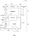
FIG. 1 is a schematic illustration of a two-fluid cooling system that may incorporate embodiments of the present disclosure; -
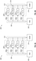
FIG. 2A is a schematic illustration of a cooling system that may incorporate embodiments of the present disclosure, in a first state of operation; -
FIG. 2B illustrates the cooling system ofFIG. 2A in a second state of operation; -
FIG. 3 is a schematic illustration of a cooling system in accordance with an embodiment of the present disclosure; -
FIG. 4 is a schematic illustration of a single fluid cooling system that may incorporate embodiments of the present disclosure; -
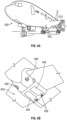
FIG. 5A is a schematic illustration of an aircraft that can incorporate various embodiments of the present disclosure; and -
FIG. 5B is a schematic illustration of a bay section of the aircraft ofFIG. 5A . - As shown and described herein, various features of the disclosure will be presented. Various embodiments may have the same or similar features and thus the same or similar features may be labeled with similar reference numerals. Although similar reference numbers may be used in a generic sense, various embodiments will be described and various features may include changes, alterations, modifications, etc. as will be appreciated by those of skill in the art, whether explicitly described or otherwise would be appreciated by those of skill in the art.
- Referring to
FIG. 1 , a schematic illustration of a two-fluid cooling cycle 100 is shown. The two-fluid cooling cycle 100 is configured to provide acold sink 102 that is thermally coupled with one or more components and/or fluids associated with one or more components (illustrated as heat load 104), to provide cooling thereto. For example, in some embodiments or configurations, thecold sink 102 may be a cold plate having internal fluid passages for receiving a fluid of the two-fluid cooling cycle 100 which absorbs heat from theheat load 104. Theheat load 104 may be powered electronics of an aircraft, a working fluid line of a cooling loop/cycle, or the like, and/or portions thereof as will be appreciated by those of skill in the art. Theheat load 104, and heat loads described and employed herein, may be, for example and without limitation, electronic devices such as computer processes, motor controllers, radio/radar systems, power amplifiers, diodes, inductors, motors, and/or other electric and/or electronic devices. - To operate as a source of heat removal from the
heat load 104, thecold sink 102 is part of acoolant loop 106. Thecoolant loop 106 is a closed-loop system that includes thecold sink 102, anevaporator 108, and apump 110. Thecoolant loop 106 includes a coolant fluid within a closed-loop flow path that passes from thecold sink 102, into and through theevaporator 108, is pumped in pressure at thepump 110, and returned to thecold sink 102. As the coolant passes through thecold sink 102, it will pick up heat from theheat load 104 and increase in temperature. The heated coolant will then enter theevaporator 108 where excess heat will be extracted and the coolant will be cooled. The cooled coolant will then be increased in pressure at thepump 110 to ensure that the coolant is in a liquid phase prior to entering thecold sink 102. It will be appreciated that in some configurations, the coolant of thecoolant loop 106 remains in a liquid phase throughout thecoolant loop 106, thereby preventing or avoiding maldistribution or other complications due to phase changes and/or flow disruptions. - The heat picked up by the coolant of the
coolant loop 106 within thecold sink 102 is removed at theevaporator 108. Theevaporator 108 is part of thecoolant loop 106 and part of arefrigerant loop 112. Theevaporator 108 receives, as a first working fluid, the coolant of thecoolant loop 106 and, as a second working fluid, a refrigerant of therefrigerant loop 112. The refrigerant will pick up heat from the coolant of thecoolant loop 106 within theevaporator 108 and enter a vapor phase. The heated refrigerant (vapor) will then be compressed within acompressor 114, condensed (from vapor to liquid) within a condenser 116 (e.g., a heat exchanger to remove heat), and then expanded within or through avalve 118 before returning to theevaporator 108 as a two-phase fluid, where it will pick up heat and evaporate into the vapor phase through interaction with the heated coolant of thecoolant loop 106 within theevaporator 108. Thevalve 118 may be an expansion valve, controllable valve, or the like, as will be appreciated by those of skill in the art. - Thermal management of temperature-sensitive components under harsh environments often require a coolant at temperatures below ambient. The two-
fluid cooling cycle 100 shown inFIG. 1 provides such cooling. A vapor compression cycle (e.g., refrigerant loop 112) is used to chill a secondary (indirect) coolant (e.g., coolant loop 106) to required sub-ambient temperatures (FIG. 1 ), at the expense of system efficiency, size, and weight due to the required components and inefficiencies. For example, excess vapor cycle temperatures lift may be required to drive heat transfer in an evaporator. Further, relatively large flow rates may be required in a liquid portion of the loop(s) to maintain consistent cooling for high heat loads. Furthermore, additional temperature lift may be quired to drive heat transfer in the condenser, particularly if the coolant temperature is below ambient. These and other inefficiencies may be addressed, at least in part, through implementations of embodiments of the present disclosure. - In the two-
fluid cooling cycle 100 ofFIG. 1 , two separate working fluids are used. A coolant is used in thecoolant loop 106 and a separate refrigerant is used in therefrigerant loop 112. In some configurations, the coolant of thecoolant loop 106 may be, for example and without limitation, water, propylene-glycol water mixture, ethylene-glycol water mixture, etc., and the refrigerant of therefrigerant loop 112 may be, for example and without limitation, 1,1,1,2-Tetrafluoroethane (R-134a), a mixture of difluoromethane and pentafluoroethane (R-410A), 2,3,3,3-Tetrafluoropropene (R-1234yf), or 1,1,1,3,3,3-Hexafluoropropane (236fa), etc. Using two separate fluids can result in inefficiencies, such as requiring two separate fluid systems, ensuring proper thermal exchange occurs at the correct locations of the respective loops, and the like. - In view of the above and to provide other advantages, embodiments of the present disclosure are directed to single fluid cooling systems. In accordance with embodiments of the present disclosure, a refrigerant system/loop is used to directly cool the sensitive components (e.g., heat load 104) via an evaporator cold plate (e.g., cold sink 102), thereby eliminating the additional components associated with the indirect loop and their inefficiencies (i.e., components of the refrigerant loop 112). This is achieved through two-phase cooling, where a working fluid is converted between different phase states to accommodate thermal pick up and operate as a heat sink to the respective component(s) and/or system(s). In single-fluid, two-phase cooling systems, using a two-phase mixture coming directly from an expansion valve (e.g., valve 118) of the vapor compression cycle (e.g., refrigerant loop 112) can be problematic, as two-phase flow can present flow maldistribution issues that result in system failure under high heat loads.
- In some embodiments, the
system 100 may be configured to use a single fluid, such as a two-phase fluid. In some such embodiments, theevaporator 108 may be replaced by a separator (e.g., gravity separator or the like). The separator may be configured to receive a single stream/mixture from the twoloops - Embodiments of the present disclosure are directed to passive flow controllers configured to control flow through a heat load cooling path of a heat load to accommodate different loads while ensuring cooling to various connected components. In accordance with some embodiments of the present disclosure, a high pressure drop element, such as a valve, flow restrictor, orifice, or the like, is arranged upstream of each heat load cooling path in a cold sink. As such, the majority of the pressure drop through each parallel heat load cooling path occurs in the pressure drop elements. According to some embodiments, a pressure drop through a pressure drop element is designed to be larger than a pressure drop across the associated (downstream) cold plate (or as compared to a system without such pressure drop elements). Thus, when a heat load in a given heat load cooling path increases and results in a higher pressure drop across the given heat load cooling path, the overall pressure drop and subsequent flow rate will not be significantly affected. In some embodiments, an overall liquid-side pressure drop and pumping power requirement may increase. However, pumping powers typically are negligible in pumped two-phase cooling loops, especially when compared to compressor and fan powers. Thus, the system efficiency is not expected to be significantly affected.
- Referring now to
FIGS. 2A-2B , a schematic configuration of acooling assembly 200 in accordance with an embodiment of the present disclosure is shown. The coolingassembly 200 may be incorporated into cooling systems, such as shown and described above. As shown, the coolingassembly 200 includes aninlet 202 configured to provide or supply a two-phase cooling fluid in a liquid state. The fluid may be provided into aninlet manifold 204 and divided into multiple separate heatload cooling paths load cooling paths 206a-d pass through acold sink 208, such as a cold plate or the like. Thecold sink 208 includes a number ofheat loads cold sink 208, with eachheat load 210a-d arranged along a respective heatload cooling path 206a-d of thecold sink 208. The fluid will pass along the respective heatload cooling path 206a-d, enter anoutlet manifold 212 and out anoutlet 214. During the passage from theinlet manifold 204 to theoutlet manifold 212, the fluid will pick up heat from the heat loads 210a-d and may change phase, such as from a liquid to a vapor. This change in state requires energy that is taken from therespective heat loads 210a-d. Theoutlet manifold 212 may be configured to receive a two-phase state of the fluid to be directed out theoutlet 214, where the fluid may be cooled again, as described above (e.g., separator, pump, evaporator, or the like). - In an example operation, each of the heat loads 210a-d may be substantially the same. For example, each
heat load 210a-d may be a 1x kW (where x is an arbitrary load value). In such configuration, where eachheat load 210a-d is the same or substantially the same, the throughflow for each heatload cooling path 206a-d will be the same or substantially the same. In the example of heat loads of 1x kW, the throughflow of each heatload cooling path 206a-d may be 1y kg/s (where y is an arbitrary flow value). This is illustratively shown/labeled inFIG. 2A . In such a configuration, the throughflows of each heatload cooling path 206a-d is the same, and thus consistent cooling and heat removal at the heat loads 210a-d may be achieved. - However, as shown in
FIG. 2B , if the heat load of one of the heat loads 210a-d changes and is different from the other of the heat loads 210a-d, the result can be a disrupted flow that can impact the cooling capacity. For example, based on a similar classification of eachheat load 210a-d, the first, third, andfourth heat loads load cooling paths second heat load 210b, in this illustrative example, may have a heat load of 10x kW (i.e., ten times greater heat load than the other heat loads).FIG. 2B is illustrative of the fact that a pressure drop in a two-phase flow increases with increasing heat flux, resulting in a high heat load component receiving less flow. In this configuration, for example, the flow through the second heatload cooling path 206b has a flow of 0.3y kg/s (as compared to 1y kg/s for each of the other heatload cooling paths portion 216 downstream from thesecond heat load 210b and within theoutlet manifold 212. This results in maldistribution of flow, where a low flow through the heatload cooling path 206b is present for thehigh heat load 210b, and thus proper cooling of theheat load 210b may not be possible. - One possible solution to deal with this inherent flow maldistribution issue is via use of a thermosyphon. Thermosyphons work by using the generated vapor itself to create static pressure difference between the inlet and outlet, which drives the flow. If the heat load of a certain component increases, so does the static pressure, resulting in more flow to handle the increased heat load. However, while maldistribution is remedied, thermosyphons rely on gravity for operation and thus limits their maximum heat flux and makes them unreliable in variable g-load applications. Similarly, while capillary flow is capable of providing more flow under a higher heat load, in practice, the range of applicable heat fluxes is low. Accordingly, embodiments of the present disclosure are directed to controlling pressure drops across the heat loads, even when the heat loads are not equal, and thus achieving more efficient cooling.
- Referring now to
FIG. 3 , a schematic configuration of acooling assembly 300 in accordance with an embodiment of the present disclosure is shown. The coolingassembly 300 may be incorporated into cooling systems, such as shown and described above. As shown, the coolingassembly 300 includes aninlet 302 configured to provide or supply a two-phase cooling fluid in a liquid state. The fluid may be provided into aninlet manifold 304 and divided into multiple separate heatload cooling paths load cooling paths 306a-d pass through acold sink 308, such as a cold plate or the like. Thecold sink 308 includes a number ofheat loads cold sink 308, with eachheat load 310a-d arranged along a respective heatload cooling path 306a-d of thecold sink 308. The fluid will pass along the respective heatload cooling path 306a-d, enter anoutlet manifold 312 and out anoutlet 314. During the passage from theinlet manifold 304 to theoutlet manifold 312, the fluid will pick up heat from the heat loads 310a-d and may change phase, such as from a liquid to a vapor. This change in state requires energy that is taken from therespective heat loads 310a-d. Theoutlet manifold 312 may be configured to receive a vapor-phase, liquid-phase, or two-phase state of the fluid to be directed out theoutlet 314, where the fluid may be cooled again, as described above (e.g., separator, pump, evaporator, or the like). - As discussed above with respect to
FIGS. 2A-2B , when the heat loads change between thedifferent heat loads 310a-d, the flow rates through the respective heatload cooling paths 306a-d may be significantly impacted. However, as shown inFIG. 3 , each heatload cooling path 306a-d is configured with a respectivepressure regulating elements 316a-d. Thepressure regulating elements 316a-d may be high pressure drop components (e.g., valves, orifices, flow restrictors, etc.) arranged along the respective heatload cooling paths 306a-d at a position upstream of therespective heat loads 310a-d. By positioning thepressure regulating elements 316a-d upstream from therespective heat loads 310a-d, the majority of the pressure drop through each parallel heatload cooling path 306a-d occurs in thepressure regulating elements 316a-d. It will be appreciated that the pressure regulating elements may be arranged downstream from the respective heat loads, and thus the configuration shown inFIG. 3 is not intended to be limiting, but rather is provided for illustrative and explanatory purposes. The location of the pressure regulating elements is selected to ensure that the fluid is a single-phase when it passes through or across the pressure regulating elements. - Each
pressure regulating element 316a-d may be set to achieve a preset pressure drop that is greater than a maximum expected pressure drop across any of the heat loads 310a-d. Because the pressure drop through thepressure regulating elements 316a-d is designed to be larger than the pressure drop across therespective heat load 310a-d along the respective heatload cooling paths 306a-d, when aheat load 310a-d in thecold sink 308 increases and results in a higher pressure drop, the overall pressure drop and subsequent flow rate will not be significantly affected. In some embodiments, because of the higher set pressure drop at thepressure regulating elements 316a-d, the overall liquid-side pressure drop and pumping power increases. Nevertheless, pumping power is typically negligible in pumped two-phase cooling loops, especially when compared to compressor and fan power requirements. Thus, the system efficiency is not expected to be significantly affected. - For example, similar to that discussed above with respect to
FIGS. 2A-2B , eachheat load 310a-d may have a power level of 1x kW (where x is an arbitrary load value). In the example of heat loads of 1x kW, the throughflow of each heatload cooling path 306a-d may be 1y kg/s (where y is an arbitrary flow value). In such a configuration, the throughflows of each heatload cooling path 306a-d is the same, and thus consistent cooling and heat removal at the heat loads 310a-d may be achieved. In the event that thesecond heat load 310b increases in load to 10x, the throughflow of 1y kg/s is not significantly altered, as it was in the embodiment ofFIG. 2B , and remains at 1y kg/s. This is because the pressure drop across thesecond heat load 310b remains substantially constant. As shown, eachheat load 310a-d has a respective pressure drop of 1z Pa. This is achieved as a result of the upstreampressure regulating elements 316a-d which are configured with greater pressure drops than the highest pressure drop achievable across eachheat load 310a-d. For example, as illustratively shown inFIG. 3 , eachpressure regulating element 316a-d may be configured to provide a pressure drop across the respectivepressure regulating element 316a-d of 10z Pa (i.e., ten times the pressure drop across the associatedheat loads 310a-d). In accordance with embodiments of the present disclosure, the pressure drop across the pressure regulating elements may be any pressure drop that is greater than the highest pressure drop that would occur at the greatest heat load without such pressure regulating elements. In this example embodiment, the pressure drop is ten times greater. However, it will be appreciated that any pressure drop that is greater than the highest pressure drop that would occur at the greatest heat load without such pressure regulating elements. That is, the exact factor by which the pressure regulating elements need to be larger than the maximum pressure drop depends on the exact system and operational conditions being considered. For some configurations, the factor might have to be 10x, forothers 1x might be sufficient. - In accordance with embodiments of the present disclosure, a multi-path cold sink is modified with upstream pressure regulating elements that force a pressure drop in the fluid prior to the fluid being supplied into and through the respective heat load cooling paths of the cold sink. The forced upstream pressure drop removes the flow response that is typical when a heat load is increased (e.g., as shown in
FIG. 2B ). In accordance with some embodiments, the pressure drops of each pressure regulating element is the same. The pressure drop of the pressure regulating elements is preset or predefined and set to be greater than a maximum pressure drop of any of the associated heat loads. The flow rates in such systems are set to accommodate the highest heat load of a given heat load operation. With the pressure drops being equal for each heat load cooling path, when a load changes at a given heat load downstream from the pressure regulating elements, the result is not as dramatic as present in systems without such pressure regulating elements (e.g.,FIGS. 2A-2B ). - Referring now to
FIG. 4 , a schematic illustration of a single-fluid, two-phase cooling system 400 is shown. Thesystem 400 may be configured to include a cold sink similar to that shown and described above. As shown, thesystem 400 includes a cold sink (e.g., cold plate 402) that may be thermally coupled to a plurality of heat loads (not shown) to provide cooling thereto. In this configuration, because a single fluid (e.g., a refrigerant) is used in the cycle of thesystem 400, a two-phase fluid may exit thecold plate 402 where heat was picked up from the coupled heat loads. The refrigerant within thesystem 500 may be, for example and without limitation, 1,1,1,2-Tetrafluoroethane (R-134a) or 2,3,3,3-Tetrafluoropropene (R-1234yf), although other refrigerants may be used without departing from the scope of the present disclosure. In this illustrative embodiment, the two-phase cooling fluid will be separated into liquid and vapor components within aseparator 404. In aliquid loop 406 of thesystem 400, the liquid portion of the refrigerant sourced from theseparator 404 is increased in pressure through apump 408 and provided into thecold plate 402 for cooling purposes. The cooling fluid within theliquid loop 406 is maintained in liquid form as it enters thecold plate 402, which may include pressure regulating elements associated with each heat load that is thermally coupled to thecold plate 402. - In this embodiment, a vapor portion of the cooling fluid within the
separator 404 is directed into avapor loop 410. In thevapor loop 410, the refrigerant will be compressed within acompressor 412 and then condensed to a liquid state within acondenser 414. The liquid is then expanded into a two-phase state at a valve 416 (e.g., expansion valve, controllable valve, etc.). The two-phase fluid, from each of theliquid loop 406 and thevapor loop 410, are joined at theseparator 404. Theseparator 404 may operate as a flash tank where the two-phases exiting thevalve 416 and thecold plate 402 are separated into liquid and vapor phases by gravity or other mechanism. Thesystem 400 provides a relatively simple complexity system that minimizes the number of components while providing for efficient cooling at a cold sink. Thesystem 400 uses a single fluid (e.g., refrigerant, and no need for a separate coolant) and a single separator that divides the flows of fluids of the refrigerant (e.g., vapor versus liquid). - In some embodiments, an inlet manifold associated with the
cold plate 402 may be arranged between thepump 408 and thecold plate 402 to receive the liquid cooling fluid. Similarly, a downstream outlet manifold may be arranged at the downstream end of thecold plate 402 to receive and combine the cooling fluid as it exits thecold plate 402. The cooling fluid may be in liquid form, two-phase form, or vapor form as it exits thecold plate 402, and then directed into the separator 404 (joined with the fluid from thevapor loop 410 before, at, or in the separator 404). The system 400 (or the other above described systems and variations thereon) may be used for cooling of aircraft heat loads, such as for powered electronics or the like. - In accordance with embodiments of the present disclosure, the pressure regulating elements may be configured to provide a predetermined change in mass flow rate of a fluid through the respective pressure regulating element. For example, in some embodiments, and without limitation, the pressure regulating elements may be configured to restrict or reduce a mass flow rate by 10%-90%, depending on the specific configuration, heat loads, etc. In some embodiments, the pressure regulating elements may be configured to reduce the mass flow rate by 10%-70%, 15%-50%, 20%-45%, 20%-30%, etc. It will be appreciated that the reduction in mass flow rate may be set at a single or small range of values for highly tuned or configuration systems (e.g., reduction in mass flow rate of about 25%, 30%, 45%, 60%, etc.).
-
FIGS. 5A-5B are schematic illustrations of anaircraft 500 that can employ one or more embodiments of the present disclosure. As shown inFIGS. 5A-5B , theaircraft 500 includesbays 502 beneath a center wing box. Thebays 502 can contain and/or support one or more components of theaircraft 500. For example, in some configurations, theaircraft 500 can include environmental control systems, electronics systems, and/or fuel tank inerting systems within thebays 502. As shown inFIG. 5B , thebays 502 includebay doors 504 that enable installation and access to one or more components (e.g., environmental control systems, electronics systems, fuel tank inerting systems, etc.). During operation of the onboard systems and components of theaircraft 500, air that is external to theaircraft 500 can be provided to such systems within thebay doors 504 through one or moreram air inlets 506. The air may then flow through the systems to be processed and supplied to various components or locations within the aircraft 500 (e.g., flight deck, passenger cabin, etc.). Some air may be exhausted through one or more ramair exhaust outlets 508. The condensers described above, and part of the cooling systems, may be arranged in fluid or thermal interaction with the ram air or may be arranged within ram air ducts of the aircraft, for aircraft applications of the cooling systems described herein. - Also shown in
FIG. 5A , theaircraft 500 includes one ormore engines 510. Theengines 510 are typically mounted on wings of theaircraft 500, but may be located at other locations depending on the specific aircraft configuration. In some aircraft configurations, air can be bled from theengines 510 and supplied to the onboard systems, as will be appreciated by those of skill in the art. - It will be appreciated that the cooling systems or portions thereof, such as those shown and described above, may be installed onboard an aircraft, such as
aircraft 500 shown inFIGS. 5A-5B . The cooling systems may be configured to cool onboard heat loads. These onboard employments may be thermally coupled to or include a cold sink or cold plate which functions as shown and described above. As such, a portion of the fluid of the cooling systems described above may be passed through or used to cool such heat loads. In some embodiments, the cooling required at the condensers of the systems to generate the liquid state of the fluid in the vapor loops may be provided by a condenser arranged in a ram air duct or configured to receive such air (or treated air). Although shown to be implemented onboard an aircraft, it will be appreciated that embodiments of the present disclosure may be employed in systems such as motor cooling in electric vehicles, server rack cooling in data centers, or the like. - Advantageously, embodiments described herein provide for improved efficiency cooling systems and cycles. For example, fewer structural components may be required in the systems shown and described herein, thus resulting in lower complexity systems and lower weight. Additionally, embodiments of the present disclosure provide for single-fluid, multi-phase cooling systems that maintain consistent pressure drops and thus flow rates within and through the cold sinks of the systems. In accordance with embodiments of the present disclosure, the upstream pressure regulating elements provide a response that is instantaneous and passive, and accordingly, can never fail. That is, by forcing a pressure drop upstream from the heat loads on the cold sink, the flow through the cold sink is not substantially altered, as the primary pressure drop is forced at an upstream location from the heat loads. Further, although pumping power will be increased to achieve the higher pressure drop at the upstream location, such increase in pump is a relatively small contribution to an overall system power consumption, and thus the effect on system efficiency will be negligible as compared to the improvements achieved by inclusion of the pressure regulating elements.
- The use of the terms "a", "an", "the", and similar references in the context of description (especially in the context of the following claims) are to be construed to cover both the singular and the plural, unless otherwise indicated herein or specifically contradicted by context. The modifier "about" used in connection with a quantity is inclusive of the stated value and has the meaning dictated by the context (e.g., it includes the degree of error associated with measurement of the particular quantity). All ranges disclosed herein are inclusive of the endpoints, and the endpoints are independently combinable with each other. As used herein, the terms "about" and "substantially" are intended to include the degree of error associated with measurement of the particular quantity based upon the equipment available at the time of filing the application. For example, the terms may include a range of ± 8%, or 5%, or 2% of a given value or other percentage change as will be appreciated by those of skill in the art for the particular measurement and/or dimensions referred to herein.
- While the present disclosure has been described in detail in connection with only a limited number of embodiments, it should be readily understood that the present disclosure is not limited to such disclosed embodiments. Rather, the present disclosure can be modified to incorporate variations which fall within the scope of the invention as defined by the claims. Additionally, while various embodiments of the present disclosure have been described, it is to be understood that aspects of the present disclosure may include only some of the described embodiments. Accordingly, the present disclosure is not to be seen as limited by the foregoing description but is only limited by the scope of the appended claims.
Claims (15)
- A cooling system comprising:a cold sink (102) comprising a plurality of heat load cooling paths (206a - d);a heat load (310a - d) associated with each heat load cooling path of the plurality of heat load cooling paths;an inlet (202) configured to supply a cooling fluid into the cold sink;an outlet (214) configured to receive the cooling fluid after passing through the plurality of heat load cooling paths of the cold sink; anda pressure regulating element (316a - d) arranged along each heat load cooling path, each pressure regulating element arranged between the inlet and the heat load along each heat load cooling path and configured to cause a pressure drop in the cooling fluid prior to passing the cooling fluid to each heat load,wherein the pressure drop caused by each pressure regulating element is the same and is a pressure drop greater than a maximum pressure drop across each heat load of a system without such pressure regulating elements.
- The cooling system of claim 1, wherein the cooling fluid is 1,1,1,2-Tetrafluoroethane (R-134a), a mixture of difluoromethane and pentafluoroethane (R-410A), 2,3,3,3-Tetrafluoropropene (R-1234yf), or 1,1,1,3,3,3-Hexafluoropropane (236fa).
- The cooling system of claim 1 or 2, wherein the heat load is a powered electronics component of an aircraft.
- The cooling system of any preceding claim, further comprising a pump (110) arranged upstream of the inlet.
- The cooling system of any preceding claim, further comprising an evaporator (108) arranged downstream of the outlet.
- The cooling system of any preceding claim, wherein the pressure drop of each pressure regulating element is at least ten times greater than the maximum pressure drop.
- The cooling system of any preceding claim, further comprising an inlet manifold (204) arranged between the inlet and the pressure regulating elements.
- The cooling system of any preceding claim, further comprising an outlet manifold (212) arranged between the heat loads and the outlet.
- The cooling system of any preceding claim, wherein each pressure regulating element is a valve.
- The cooling system of any of claims 1 to 8, wherein each pressure regulating element is an orifice along each heat load cooling path.
- The cooling system of any preceding claim, wherein the cooling fluid is a liquid at the inlet and a two-phase fluid at the outlet.
- The cooling system of claim 11, further comprising a separator (404) arranged downstream from the outlet and configured to receive the cooling fluid and separate such fluid into a liquid flow path and a vapor flow path, wherein each of the liquid flow path and a vapor flow path define a closed-loop system centered on the cold sink.
- The cooling system of claim 12, further comprising a pump arranged downstream from the separator and upstream of the cold sink along the liquid flow path, the pump configured to boost a pressure of the cooling fluid in the liquid flow path.
- The cooling system of claim 12 or 13, further comprising a compressor (412), a condenser (414), and an expansion valve (118) arranged along the vapor flow path downstream from the separator and upstream from the cold sink.
- An aircraft cooling system comprising:a cooling system (400) as claimed in any preceding claim, the heat loads beinga plurality of aircraft heat loads, and wherein each heat load cooling path is associated with one of the plurality of aircraft heat loads.
Applications Claiming Priority (1)
| Application Number | Priority Date | Filing Date | Title |
|---|---|---|---|
| US17/944,641 US12302541B2 (en) | 2022-09-14 | 2022-09-14 | Stable pumped two-phase cooling |
Publications (1)
| Publication Number | Publication Date |
|---|---|
| EP4339532A1 true EP4339532A1 (en) | 2024-03-20 |
Family
ID=88017683
Family Applications (1)
| Application Number | Title | Priority Date | Filing Date |
|---|---|---|---|
| EP23196993.2A Pending EP4339532A1 (en) | 2022-09-14 | 2023-09-12 | Cooling system and aircraft cooling system comprising the same |
Country Status (2)
| Country | Link |
|---|---|
| US (1) | US12302541B2 (en) |
| EP (1) | EP4339532A1 (en) |
Citations (5)
| Publication number | Priority date | Publication date | Assignee | Title |
|---|---|---|---|---|
| US6742345B2 (en) * | 2002-03-27 | 2004-06-01 | The Penray Companies, Inc. | Temperature control system using aqueous 1,3-propanediol solution |
| US20130000335A1 (en) * | 2003-12-05 | 2013-01-03 | Liebert Corporation | Cooling system for high density heat load |
| US20140102132A1 (en) * | 2008-08-07 | 2014-04-17 | Hill Phoenix, Inc. | Modular co2 refrigeration system |
| US10017032B2 (en) * | 2016-02-16 | 2018-07-10 | The Boeing Company | Thermal management systems and methods |
| US11231209B2 (en) * | 2016-05-16 | 2022-01-25 | Epta S.P.A. | Refrigeration plant with multiple evaporation levels and method of managing such a plant |
Family Cites Families (25)
| Publication number | Priority date | Publication date | Assignee | Title |
|---|---|---|---|---|
| US6330800B1 (en) | 1999-04-16 | 2001-12-18 | Raytheon Company | Apparatus and method for achieving temperature stability in a two-stage cryocooler |
| US8351206B2 (en) * | 2010-06-29 | 2013-01-08 | International Business Machines Corporation | Liquid-cooled electronics rack with immersion-cooled electronic subsystems and vertically-mounted, vapor-condensing unit |
| US8184436B2 (en) * | 2010-06-29 | 2012-05-22 | International Business Machines Corporation | Liquid-cooled electronics rack with immersion-cooled electronic subsystems |
| US8179677B2 (en) * | 2010-06-29 | 2012-05-15 | International Business Machines Corporation | Immersion-cooling apparatus and method for an electronic subsystem of an electronics rack |
| US8955347B2 (en) * | 2011-07-21 | 2015-02-17 | International Business Machines Corporation | Air-side economizer facilitating liquid-based cooling of an electronics rack |
| US8953317B2 (en) * | 2011-10-26 | 2015-02-10 | International Business Machines Corporation | Wicking vapor-condenser facilitating immersion-cooling of electronic component(s) |
| US8619425B2 (en) * | 2011-10-26 | 2013-12-31 | International Business Machines Corporation | Multi-fluid, two-phase immersion-cooling of electronic component(s) |
| US8941994B2 (en) * | 2012-09-13 | 2015-01-27 | International Business Machines Corporation | Vapor condenser with three-dimensional folded structure |
| US9261308B2 (en) * | 2012-11-08 | 2016-02-16 | International Business Machines Corporation | Pump-enhanced, sub-cooling of immersion-cooling fluid |
| US9042098B2 (en) * | 2012-11-12 | 2015-05-26 | International Business Machines Corporation | Air-cooling and vapor-condensing door assembly |
| US9357675B2 (en) * | 2013-10-21 | 2016-05-31 | International Business Machines Corporation | Pump-enhanced, immersion-cooling of electronic component(s) |
| US9282678B2 (en) * | 2013-10-21 | 2016-03-08 | International Business Machines Corporation | Field-replaceable bank of immersion-cooled electronic components and separable heat sinks |
| US9332674B2 (en) * | 2013-10-21 | 2016-05-03 | International Business Machines Corporation | Field-replaceable bank of immersion-cooled electronic components |
| US20160120065A1 (en) * | 2014-10-27 | 2016-04-28 | Ebullient, Llc | Manifold for a cooling system |
| US10085367B2 (en) * | 2015-03-12 | 2018-09-25 | International Business Machines Corporation | Minimizing leakage in liquid cooled electronic equipment |
| US10156873B2 (en) * | 2015-12-21 | 2018-12-18 | Dell Products, L.P. | Information handling system having fluid manifold with embedded heat exchanger system |
| GB2548123A (en) | 2016-03-09 | 2017-09-13 | Rolls Royce Plc | Aircraft superconducting electrical propulsion system |
| DE102016207517A1 (en) | 2016-05-02 | 2017-11-02 | Siemens Aktiengesellschaft | Propulsion system for aircraft with electric generator |
| US10162396B2 (en) * | 2017-04-18 | 2018-12-25 | Baidu Usa Llc | Method and system for removing heat using heat removal liquid based on workload of server components of electronic racks |
| US10667437B2 (en) * | 2018-04-12 | 2020-05-26 | Baidu Usa Llc | Liquid distribution unit design for liquid cooling of electronic racks of a data center |
| US11201102B2 (en) * | 2018-05-10 | 2021-12-14 | International Business Machines Corporation | Module lid with embedded two-phase cooling and insulating layer |
| US10925190B2 (en) * | 2018-06-04 | 2021-02-16 | Baidu Usa Llc | Leak detection and response system for liquid cooling of electronic racks of a data center |
| US11744040B2 (en) * | 2020-03-23 | 2023-08-29 | Baidu Usa Llc | Optimal control logic in liquid cooling solution for heterogeneous computing |
| US11273925B1 (en) * | 2020-10-14 | 2022-03-15 | Rolls-Royce North American Technologies Inc. | Thermal management system and method for cooling a hybrid electric aircraft propulsion system |
| US11959669B2 (en) * | 2021-05-06 | 2024-04-16 | Rolls-Royce North American Technologies Inc. | Bimodal cooling system |
-
2022
- 2022-09-14 US US17/944,641 patent/US12302541B2/en active Active
-
2023
- 2023-09-12 EP EP23196993.2A patent/EP4339532A1/en active Pending
Patent Citations (5)
| Publication number | Priority date | Publication date | Assignee | Title |
|---|---|---|---|---|
| US6742345B2 (en) * | 2002-03-27 | 2004-06-01 | The Penray Companies, Inc. | Temperature control system using aqueous 1,3-propanediol solution |
| US20130000335A1 (en) * | 2003-12-05 | 2013-01-03 | Liebert Corporation | Cooling system for high density heat load |
| US20140102132A1 (en) * | 2008-08-07 | 2014-04-17 | Hill Phoenix, Inc. | Modular co2 refrigeration system |
| US10017032B2 (en) * | 2016-02-16 | 2018-07-10 | The Boeing Company | Thermal management systems and methods |
| US11231209B2 (en) * | 2016-05-16 | 2022-01-25 | Epta S.P.A. | Refrigeration plant with multiple evaporation levels and method of managing such a plant |
Also Published As
| Publication number | Publication date |
|---|---|
| US20240090186A1 (en) | 2024-03-14 |
| US12302541B2 (en) | 2025-05-13 |
Similar Documents
| Publication | Publication Date | Title |
|---|---|---|
| EP3553418B1 (en) | Thermal management system including two-phased pump loop and thermal energy storage | |
| EP4339531A1 (en) | Cooling system and aircraft cooling system using the same | |
| EP2969756B1 (en) | Adaptive trans-critical co2 cooling systems for aerospace applications | |
| CN1867801B (en) | Systems, devices and methods for passively and actively cooling at least one enclosed space | |
| US9676484B2 (en) | Adaptive trans-critical carbon dioxide cooling systems | |
| US8439306B2 (en) | Thermal management system with staged cooling | |
| EP2920075B1 (en) | Aircraft vehicle thermal management system and method | |
| US20180045432A9 (en) | Thermal management system controlling dynamic and steady state thermal loads | |
| EP4567351A1 (en) | Vapor compression cycle with direct pumped two-phase cooling | |
| US9706685B2 (en) | Cooling system for high density heat loads | |
| US20090077981A1 (en) | Topping Cycle for a Sub-Ambient Cooling System | |
| EP3590839B1 (en) | Pressure optimized sourcing of cabin pressurization and component air cooling | |
| EP3054238B1 (en) | Charge control system for trans-critical vapor cycle systems | |
| EP3051229B1 (en) | Thermal management system controlling dynamic and steady state thermal loads | |
| US12302541B2 (en) | Stable pumped two-phase cooling | |
| EP2650218B1 (en) | Aircraft thermal control system and method of operating an aircraft thermal control system | |
| EP4553409A1 (en) | Thermal management system for future vertical lift aircraft | |
| EP3800409B1 (en) | Refrigeration circuits, environmental control systems, and methods of controlling flow in refrigeration circuits | |
| US20090101311A1 (en) | System and Method for Cooling Using Two Separate Coolants | |
| EP2896912B1 (en) | Aircraft cooling system | |
| CN110375451A (en) | Improved cooling system for high density heat load | |
| EP3225554B1 (en) | Aircraft air conditioning system including a thermoelectric device | |
| EP4509407A1 (en) | Air conditioning and vapor cycle system |
Legal Events
| Date | Code | Title | Description |
|---|---|---|---|
| PUAI | Public reference made under article 153(3) epc to a published international application that has entered the european phase |
Free format text: ORIGINAL CODE: 0009012 |
|
| STAA | Information on the status of an ep patent application or granted ep patent |
Free format text: STATUS: THE APPLICATION HAS BEEN PUBLISHED |
|
| AK | Designated contracting states |
Kind code of ref document: A1 Designated state(s): AL AT BE BG CH CY CZ DE DK EE ES FI FR GB GR HR HU IE IS IT LI LT LU LV MC ME MK MT NL NO PL PT RO RS SE SI SK SM TR |
|
| STAA | Information on the status of an ep patent application or granted ep patent |
Free format text: STATUS: REQUEST FOR EXAMINATION WAS MADE |
|
| 17P | Request for examination filed |
Effective date: 20240919 |
|
| RBV | Designated contracting states (corrected) |
Designated state(s): AL AT BE BG CH CY CZ DE DK EE ES FI FR GB GR HR HU IE IS IT LI LT LU LV MC ME MK MT NL NO PL PT RO RS SE SI SK SM TR |
|
| STAA | Information on the status of an ep patent application or granted ep patent |
Free format text: STATUS: EXAMINATION IS IN PROGRESS |
|
| 17Q | First examination report despatched |
Effective date: 20250919 |