EP4339494A2 - Manifold arrangement of a heating or cooling system - Google Patents
Manifold arrangement of a heating or cooling system Download PDFInfo
- Publication number
- EP4339494A2 EP4339494A2 EP23213344.7A EP23213344A EP4339494A2 EP 4339494 A2 EP4339494 A2 EP 4339494A2 EP 23213344 A EP23213344 A EP 23213344A EP 4339494 A2 EP4339494 A2 EP 4339494A2
- Authority
- EP
- European Patent Office
- Prior art keywords
- manifold
- mounting
- mounting rail
- arrangement according
- rail
- Prior art date
- Legal status (The legal status is an assumption and is not a legal conclusion. Google has not performed a legal analysis and makes no representation as to the accuracy of the status listed.)
- Withdrawn
Links
Images
Classifications
-
- F—MECHANICAL ENGINEERING; LIGHTING; HEATING; WEAPONS; BLASTING
- F24—HEATING; RANGES; VENTILATING
- F24D—DOMESTIC- OR SPACE-HEATING SYSTEMS, e.g. CENTRAL HEATING SYSTEMS; DOMESTIC HOT-WATER SUPPLY SYSTEMS; ELEMENTS OR COMPONENTS THEREFOR
- F24D3/00—Hot-water central heating systems
- F24D3/10—Feed-line arrangements, e.g. providing for heat-accumulator tanks, expansion tanks ; Hydraulic components of a central heating system
- F24D3/1058—Feed-line arrangements, e.g. providing for heat-accumulator tanks, expansion tanks ; Hydraulic components of a central heating system disposition of pipes and pipe connections
- F24D3/1066—Distributors for heating liquids
-
- F—MECHANICAL ENGINEERING; LIGHTING; HEATING; WEAPONS; BLASTING
- F24—HEATING; RANGES; VENTILATING
- F24D—DOMESTIC- OR SPACE-HEATING SYSTEMS, e.g. CENTRAL HEATING SYSTEMS; DOMESTIC HOT-WATER SUPPLY SYSTEMS; ELEMENTS OR COMPONENTS THEREFOR
- F24D15/00—Other domestic- or space-heating systems
-
- F—MECHANICAL ENGINEERING; LIGHTING; HEATING; WEAPONS; BLASTING
- F16—ENGINEERING ELEMENTS AND UNITS; GENERAL MEASURES FOR PRODUCING AND MAINTAINING EFFECTIVE FUNCTIONING OF MACHINES OR INSTALLATIONS; THERMAL INSULATION IN GENERAL
- F16L—PIPES; JOINTS OR FITTINGS FOR PIPES; SUPPORTS FOR PIPES, CABLES OR PROTECTIVE TUBING; MEANS FOR THERMAL INSULATION IN GENERAL
- F16L3/00—Supports for pipes, cables or protective tubing, e.g. hangers, holders, clamps, cleats, clips, brackets
- F16L3/24—Supports for pipes, cables or protective tubing, e.g. hangers, holders, clamps, cleats, clips, brackets with special member for attachment to profiled girders
-
- F—MECHANICAL ENGINEERING; LIGHTING; HEATING; WEAPONS; BLASTING
- F24—HEATING; RANGES; VENTILATING
- F24D—DOMESTIC- OR SPACE-HEATING SYSTEMS, e.g. CENTRAL HEATING SYSTEMS; DOMESTIC HOT-WATER SUPPLY SYSTEMS; ELEMENTS OR COMPONENTS THEREFOR
- F24D19/00—Details
- F24D19/02—Arrangement of mountings or supports for radiators
- F24D19/0203—Types of supporting means
- F24D19/0206—Tube shaped supports inserted into a wall
-
- F—MECHANICAL ENGINEERING; LIGHTING; HEATING; WEAPONS; BLASTING
- F24—HEATING; RANGES; VENTILATING
- F24D—DOMESTIC- OR SPACE-HEATING SYSTEMS, e.g. CENTRAL HEATING SYSTEMS; DOMESTIC HOT-WATER SUPPLY SYSTEMS; ELEMENTS OR COMPONENTS THEREFOR
- F24D19/00—Details
- F24D19/02—Arrangement of mountings or supports for radiators
- F24D19/0203—Types of supporting means
- F24D19/0213—Floor mounted supporting means
-
- F—MECHANICAL ENGINEERING; LIGHTING; HEATING; WEAPONS; BLASTING
- F24—HEATING; RANGES; VENTILATING
- F24D—DOMESTIC- OR SPACE-HEATING SYSTEMS, e.g. CENTRAL HEATING SYSTEMS; DOMESTIC HOT-WATER SUPPLY SYSTEMS; ELEMENTS OR COMPONENTS THEREFOR
- F24D19/00—Details
- F24D19/02—Arrangement of mountings or supports for radiators
- F24D19/0203—Types of supporting means
- F24D19/0216—Supporting means having a rail
-
- F—MECHANICAL ENGINEERING; LIGHTING; HEATING; WEAPONS; BLASTING
- F24—HEATING; RANGES; VENTILATING
- F24D—DOMESTIC- OR SPACE-HEATING SYSTEMS, e.g. CENTRAL HEATING SYSTEMS; DOMESTIC HOT-WATER SUPPLY SYSTEMS; ELEMENTS OR COMPONENTS THEREFOR
- F24D19/00—Details
- F24D19/02—Arrangement of mountings or supports for radiators
- F24D19/022—Constructional details of supporting means for radiators
- F24D19/023—Radiators having fixed suspension means for connecting the radiator to the support means
Definitions
- the present invention relates to a manifold arrangement of a heating or cooling system comprising a manifold and means for fixing the manifold to a part of a building.
- the manifold is used to distribute a heat carrying fluid to a number of heating circuits.
- a manifold is in particular useful in connection with a floor heating system.
- the manifold can be used as a forward manifold or as a return manifold.
- the object underlying the invention is to allow a simple installation of a heating or a cooling system manifold.
- a mounting rail is a means which is commonly used in connection with installation of electric equipment.
- the mounting rail can simply be fixed to a wall or a floor of a building or any other system in which the manifold has to be fixed. Once the mounting rail has been fixed, the manifold can be connected to the mounting rail.
- the mounting rail runs parallel to the manifold. In other words, the manifold and the mounting rail have the same longitudinal extension.
- the mounting rail comprises a U-shaped cross-section having a base and two flanges at each side of the base, wherein the flanges comprise end sections running parallel to the base.
- the end sections are arranged at the ends of the flanges opposite to the end at which the base is connected to the flanges.
- the base can be connected to a wall or a floor of the building, while the flanges and the end sections together can be used to fix the manifold to the mounting rail.
- a mounting rail is commonly known as DIN rail.
- At least one mounting clip is mounted to the mounting rail, wherein the manifold is connected to the mounting clip.
- the mounting clip is used as intermediate part between the mounting rail and the manifold.
- a connection between the manifold and the mounting rail is made in two steps. In one step the mounting clip is connected to the mounting rail and in the second step the manifold is mounted to the mounting clip.
- the mounting clip is clipped on the mounting rail. Clipping a mounting clip on a mounting rail is a very quick and safe way to fix the mounting clip on the mounting rail.
- the mounting clip can be slided on the mounting rail in a longitudinal direction of the mounting rail. In other words, when the mounting clip is not in the best position for being connected to the manifold, the position of the mounting clip can be adjusted.
- the mounting clip comprises a track arrangement running perpendicular to a longitudinal extension of the mounting rail.
- the track arrangement can be used to mount the manifold to the mounting clip.
- the manifold is inserted into the track arrangement and slided to an end position in the track arrangement.
- the manifold comprises a mounting member in engagement with the track arrangement.
- the mounting member is adapted to the track arrangement of the mounting clip.
- the manifold comprises a tube and at least one functional part having a housing on an outside of the tube, wherein the mounting member is connected to the housing of the functional part.
- the functional part can be, for example, pre-setting means, a valve, or a connecting part. This functional part is fixed to the tube of the manifold by means of a housing and the housing in turn is connected to the mounting member.
- the mounting member is integral with the housing of the functional part.
- the housing is made of a plastic material, it is easily possible to integrate the mounting member into the housing.
- the track arrangement comprises at least one groove which is open in a direction parallel to the longitudinal extension of the mounting rail and the mounting member comprises a protrusion arranged in the groove.
- the groove has one side wall extending parallel to the base of the U-shape of the mounting rail. Thus, this wall prevents the manifold from moving away from the mounting rail.
- the track arrangement comprises an end stop.
- the mounting member can be inserted into the track arrangement until it reaches the end stop. No further movement of the manifold with respect to the mounting rail is possible. This facilitates the automatic positioning of the manifold with respect to the mounting rail. The consequence of the correct positioning of the manifold with respect to the mounting rail is that once the mounting rail has been correctly positioned, the manifold is also positioned correctly.
- the mounting clip comprises a protrusion arranged on spring means of the mounting clip.
- the protrusion is a means to hold the mounting member in the mounting clip.
- the protrusion can be passed by the mounting member when the mounting member is inserted into the track arrangement.
- the spring means then moves the protrusion back to a blocking position.
- the protrusion can be moved against the force of the spring means to open the track arrangement for removing of the mounting member.
- the means is formed by an elastic arm of the mounting clip.
- the elastic arm can be made of the same plastic material as the mounting clip itself. Thus, production of the mounting clip is simple.
- a mounting rail 1 is used to fix a manifold 2 in a certain position in a building, in particular at a wall or a floor of the building, in which the manifold is to be mounted.
- the manifold 2 can be used as a return manifold or as a forward manifold.
- the manifold 2 comprises a tube 3 and a number of functional parts, for example pre-setting means 4 or simply connectors 5.
- One end of the tube 3 is provided with a spigot 6 having a union nut 7.
- Each of the functional parts 4, 5 comprises a housing 8 which is used to connect the manifold 2 to the mounting rail 1.
- the mounting rail 1 has a U-shaped cross-section.
- the u-shaped cross-section comprises a base 9, wherein two flanges 10, 11 extend from the base 9.
- the flanges 10, 11 comprise end sections 12, 13 which extend parallel to the base 9 and are, in the present example, bent to the outside.
- the profile of the mounting rail 1 can also be considered as "head profile”.
- Such a mounting rail 1 is also known as "DIN rail”.
- the base 9 is provided with a number of elongated openings 14 which can be used to fix the mounting rail 1 to the wall or to the floor of a housing or any other system to which the manifold 2 has to be mounted.
- a number of mounting clips 15 is mounted to the mounting rail 1.
- the mounting clips 15 are clipped on the mounting rail 1, i.e. they have hooks 16, 17 that reach behind the end sections 12, 13.
- the mounting clips 15 can be slided on the mounting rail 1 in a longitudinal direction of the mounting rail 1.
- the mounting clip 15 comprises a track arrangement 18 which runs perpendicular to a longitudinal extension of the mounting rail 1.
- the track arrangement 18 comprises two T-shaped protrusions 19, 20, each forming two grooves 21, 22 on both sides in longitudinal direction of the mounting rail 1.
- the grooves 21, 22 are formed between a body of the mounting clip 15 and a cross bar of the T.
- the housing 8 of the functional part 4, 5 comprises a corresponding counter geometry 23 having slots 24, 25 matching the T-shaped protrusions 19, 20.
- the counter geometry 23 forms a mounting member which is integral to the housing 8 and can be brought into engagement with the track arrangement 18.
- the T-shaped protrusions 19, 20 form at the same time an end stop so that a movement of the manifold 2 onto the mounting clips 15 is stopped when an end of the slots 24, 25 reach the T-shaped protrusions 19, 20.
- the mounting clip 15 comprises another protrusion 26 which is mounted on a spring arm 27.
- the protrusion 26 is pressed towards the mounting clip 15 during mounting of the manifold 2 and then springs outwards in direction of the housing 8 when the manifold 2 has reached its final position. In this state the protrusion enters a depression 28 in the housing, which is shown in Fig. 2 .
- the manifold 2 is held in both directions perpendicular to the longitudinal extension of the mounting rail 1.
- the mounting clips 15 can be slided on the mounting rail 1 in the longitudinal direction of the mounting rail 1, the position of the mounting clips can easily be adapted to the positions of the respective functional elements on the manifold 2.
- the manifold 2 extends parallel to the longitudinal extension of the mounting rail 1.
- the manifold 2 can be connected to the mounting rail 1 not only in one position, but in a plurality of positions.
- the manifold 2 is connected to the mounting rail 1 at three positions, so that three mounting clips 15 are used.
Landscapes
- Engineering & Computer Science (AREA)
- General Engineering & Computer Science (AREA)
- Mechanical Engineering (AREA)
- Physics & Mathematics (AREA)
- Thermal Sciences (AREA)
- Chemical & Material Sciences (AREA)
- Combustion & Propulsion (AREA)
- Supports For Pipes And Cables (AREA)
- Connection Of Plates (AREA)
Abstract
Description
- The present invention relates to a manifold arrangement of a heating or cooling system comprising a manifold and means for fixing the manifold to a part of a building.
- In a heating or a cooling system the manifold is used to distribute a heat carrying fluid to a number of heating circuits. Such a manifold is in particular useful in connection with a floor heating system. The manifold can be used as a forward manifold or as a return manifold.
- For the installation of such a manifold it is not only necessary to connect the manifold with a supply line or a return line, but it is also necessary to fix the manifold in the system in which it is used, in particular in a building.
- The object underlying the invention is to allow a simple installation of a heating or a cooling system manifold.
- This object is solved with a manifold arrangement as described at the outset in that the fixing means comprise a mounting rail.
- A mounting rail is a means which is commonly used in connection with installation of electric equipment. The mounting rail can simply be fixed to a wall or a floor of a building or any other system in which the manifold has to be fixed. Once the mounting rail has been fixed, the manifold can be connected to the mounting rail.
- In an embodiment of the invention the mounting rail runs parallel to the manifold. In other words, the manifold and the mounting rail have the same longitudinal extension.
- In an embodiment of the invention the mounting rail comprises a U-shaped cross-section having a base and two flanges at each side of the base, wherein the flanges comprise end sections running parallel to the base. The end sections are arranged at the ends of the flanges opposite to the end at which the base is connected to the flanges. The base can be connected to a wall or a floor of the building, while the flanges and the end sections together can be used to fix the manifold to the mounting rail. Such a mounting rail is commonly known as DIN rail.
- In an embodiment of the invention at least one mounting clip is mounted to the mounting rail, wherein the manifold is connected to the mounting clip. The mounting clip is used as intermediate part between the mounting rail and the manifold. Thus, a connection between the manifold and the mounting rail is made in two steps. In one step the mounting clip is connected to the mounting rail and in the second step the manifold is mounted to the mounting clip. These two steps can be decoupled, so that the mounting rail can already be prepared for mounting the manifold further facilitating the installation of the manifold.
- In an embodiment of the invention the mounting clip is clipped on the mounting rail. Clipping a mounting clip on a mounting rail is a very quick and safe way to fix the mounting clip on the mounting rail.
- In an embodiment of the invention the mounting clip can be slided on the mounting rail in a longitudinal direction of the mounting rail. In other words, when the mounting clip is not in the best position for being connected to the manifold, the position of the mounting clip can be adjusted.
- In an embodiment of the invention the mounting clip comprises a track arrangement running perpendicular to a longitudinal extension of the mounting rail. The track arrangement can be used to mount the manifold to the mounting clip. The manifold is inserted into the track arrangement and slided to an end position in the track arrangement.
- In an embodiment of the invention the manifold comprises a mounting member in engagement with the track arrangement. The mounting member is adapted to the track arrangement of the mounting clip.
- In an embodiment of the invention the manifold comprises a tube and at least one functional part having a housing on an outside of the tube, wherein the mounting member is connected to the housing of the functional part. The functional part can be, for example, pre-setting means, a valve, or a connecting part. This functional part is fixed to the tube of the manifold by means of a housing and the housing in turn is connected to the mounting member.
- In an embodiment of the invention the mounting member is integral with the housing of the functional part. When, for example, the housing is made of a plastic material, it is easily possible to integrate the mounting member into the housing.
- In an embodiment of the invention the track arrangement comprises at least one groove which is open in a direction parallel to the longitudinal extension of the mounting rail and the mounting member comprises a protrusion arranged in the groove. The groove has one side wall extending parallel to the base of the U-shape of the mounting rail. Thus, this wall prevents the manifold from moving away from the mounting rail.
- In an embodiment of the invention the track arrangement comprises an end stop. The mounting member can be inserted into the track arrangement until it reaches the end stop. No further movement of the manifold with respect to the mounting rail is possible. This facilitates the automatic positioning of the manifold with respect to the mounting rail. The consequence of the correct positioning of the manifold with respect to the mounting rail is that once the mounting rail has been correctly positioned, the manifold is also positioned correctly.
- In an embodiment of the invention the mounting clip comprises a protrusion arranged on spring means of the mounting clip. The protrusion is a means to hold the mounting member in the mounting clip. The protrusion can be passed by the mounting member when the mounting member is inserted into the track arrangement. The spring means then moves the protrusion back to a blocking position. When the mounting member has to be demounted, the protrusion can be moved against the force of the spring means to open the track arrangement for removing of the mounting member.
- In an embodiment of the invention the means is formed by an elastic arm of the mounting clip. The elastic arm can be made of the same plastic material as the mounting clip itself. Thus, production of the mounting clip is simple.
- A preferred embodiment of the invention will now be described with reference to the drawing, in which:
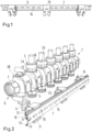
- Fig. 1
- shows a mounting rail with mounting clips,
- Fig. 2
- shows a manifold and the mounting rail,
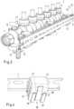
- Fig. 3
- shows the manifold connected to the mounting rail and
- Fig. 4
- shows a larger view of a mounting clip on a mounting rail.
- A
mounting rail 1 is used to fix amanifold 2 in a certain position in a building, in particular at a wall or a floor of the building, in which the manifold is to be mounted. Themanifold 2 can be used as a return manifold or as a forward manifold. - The
manifold 2 comprises atube 3 and a number of functional parts, for example pre-setting means 4 or simplyconnectors 5. One end of thetube 3 is provided with aspigot 6 having aunion nut 7. - Each of the
functional parts 4, 5 comprises ahousing 8 which is used to connect themanifold 2 to themounting rail 1. - The mounting
rail 1 has a U-shaped cross-section. The u-shaped cross-section comprises abase 9, wherein twoflanges base 9. Theflanges end sections base 9 and are, in the present example, bent to the outside. The profile of the mountingrail 1 can also be considered as "head profile". Such a mountingrail 1 is also known as "DIN rail". - The
base 9 is provided with a number ofelongated openings 14 which can be used to fix the mountingrail 1 to the wall or to the floor of a housing or any other system to which themanifold 2 has to be mounted. - As can be seen in
Fig. 1 and 2 a number of mountingclips 15 is mounted to the mountingrail 1. The mounting clips 15 are clipped on the mountingrail 1, i.e. they havehooks end sections rail 1 in a longitudinal direction of the mountingrail 1. - As can be seen in
Fig. 4 , the mountingclip 15 comprises atrack arrangement 18 which runs perpendicular to a longitudinal extension of the mountingrail 1. Thetrack arrangement 18 comprises two T-shapedprotrusions grooves rail 1. Thegrooves clip 15 and a cross bar of the T. Thehousing 8 of thefunctional part 4, 5 comprises acorresponding counter geometry 23 havingslots protrusions counter geometry 23 forms a mounting member which is integral to thehousing 8 and can be brought into engagement with thetrack arrangement 18. Thus, simply by moving themanifold 2 in a direction perpendicular to the longitudinal extension of the mountingrail 1 and by bringing thecounter geometry 23 into engagement with thetrack arrangement 8 it is possible to fix themanifold 2 to the mountingrail 1. - The T-shaped
protrusions manifold 2 onto the mountingclips 15 is stopped when an end of theslots protrusions - Furthermore, the mounting
clip 15 comprises anotherprotrusion 26 which is mounted on aspring arm 27. Theprotrusion 26 is pressed towards the mountingclip 15 during mounting of themanifold 2 and then springs outwards in direction of thehousing 8 when themanifold 2 has reached its final position. In this state the protrusion enters adepression 28 in the housing, which is shown inFig. 2 . Thus, themanifold 2 is held in both directions perpendicular to the longitudinal extension of the mountingrail 1. - Since the mounting
clips 15 can be slided on the mountingrail 1 in the longitudinal direction of the mountingrail 1, the position of the mounting clips can easily be adapted to the positions of the respective functional elements on themanifold 2. - The
manifold 2 extends parallel to the longitudinal extension of the mountingrail 1. Thus, themanifold 2 can be connected to the mountingrail 1 not only in one position, but in a plurality of positions. In the embodiment shown, themanifold 2 is connected to the mountingrail 1 at three positions, so that three mountingclips 15 are used. - It is not necessary to fix every
functional element 4, 5 to the mountingrail 1. In the present example, only every third functional element is fixed to the mountingrail 1.
Claims (14)
- Manifold arrangement of a heating or cooling system comprising a manifold (2) and means for fixing the manifold (2) to a part of a building, characterized in that the fixing means comprise a mounting rail (1).
- Manifold arrangement according to claim 1, characterized in that the mounting rail (1) runs parallel to the manifold (2).
- Manifold arrangement according to claim 1 or 2, characterized in that the mounting rail (1) comprises a U shape cross section having a base (9) and a flange (10, 11) at each side of the base (9), wherein the flanges (10, 11) comprise end sections (12, 13) running parallel to the base (9).
- Manifold arrangement according to any of claims 1 to 3, characterized in that at least one mounting clip (15) is mounted to the mounting rail (1), wherein the manifold (2) is connected to the mounting clip (15).
- Manifold arrangement according to claim 4, characterized in that the mounting clip (15) is clipped on the mounting rail (1).
- Manifold arrangement according to claim 4 or 5, characterized in that the mounting clip (15) can be shifted on the mounting rail (1) in a longitudinal direction of the mounting rail (1).
- Manifold arrangement according to any of claims 4 to 6, characterized in that the mounting clip (15) comprises a track arrangement (18) running perpendicular to a longitudinal extension of the mounting rail (1).
- Manifold arrangement according to claim 7, characterized in that the manifold (2) comprises a mounting member (23) in engagement with the track arrangement (18).
- Manifold arrangement according to claim 8, characterized in that the manifold (2) comprises a tube (3) and at least one functional part (4, 5) having a housing (8) on an outside of the tube (3), wherein the mounting member (23) is connected to the housing (8) of the functional part (4, 5).
- Manifold arrangement according to claim 9, characterized in that the mounting member (23) is integral with the housing (8) of the functional part (4, 5).
- Manifold arrangement according to any of claims 8 to 10, characterized in that the track arrangement (18) comprises at least one groove (21, 22) which is open in a direction parallel to the longitudinal extension of the mounting rail (1) and the mounting member (23) comprises a protrusion arranged in the groove (21, 22).
- Manifold arrangement according to any of claims 7 to 11, characterized in that the track arrangement (18) comprises an end stop.
- Manifold arrangement according to any of claims 7 to 12, characterized in that the mounting clip (15) comprises a protrusion (26) arranged on spring means (27) of the mounting clip.
- Manifold arrangement according to claim 13, characterized in that the spring means (27) is formed by an elastic arm of the mounting clip.
Priority Applications (1)
| Application Number | Priority Date | Filing Date | Title |
|---|---|---|---|
| EP23213344.7A EP4339494A3 (en) | 2022-03-08 | 2022-03-08 | Manifold arrangement of a heating or cooling system |
Applications Claiming Priority (2)
| Application Number | Priority Date | Filing Date | Title |
|---|---|---|---|
| EP22160654.4A EP4242525B1 (en) | 2022-03-08 | 2022-03-08 | Manifold arrangement of a heating or cooling system |
| EP23213344.7A EP4339494A3 (en) | 2022-03-08 | 2022-03-08 | Manifold arrangement of a heating or cooling system |
Related Parent Applications (2)
| Application Number | Title | Priority Date | Filing Date |
|---|---|---|---|
| EP22160654.4A Division EP4242525B1 (en) | 2022-03-08 | 2022-03-08 | Manifold arrangement of a heating or cooling system |
| EP22160654.4A Division-Into EP4242525B1 (en) | 2022-03-08 | 2022-03-08 | Manifold arrangement of a heating or cooling system |
Publications (2)
| Publication Number | Publication Date |
|---|---|
| EP4339494A2 true EP4339494A2 (en) | 2024-03-20 |
| EP4339494A3 EP4339494A3 (en) | 2024-04-03 |
Family
ID=80684167
Family Applications (2)
| Application Number | Title | Priority Date | Filing Date |
|---|---|---|---|
| EP22160654.4A Active EP4242525B1 (en) | 2022-03-08 | 2022-03-08 | Manifold arrangement of a heating or cooling system |
| EP23213344.7A Withdrawn EP4339494A3 (en) | 2022-03-08 | 2022-03-08 | Manifold arrangement of a heating or cooling system |
Family Applications Before (1)
| Application Number | Title | Priority Date | Filing Date |
|---|---|---|---|
| EP22160654.4A Active EP4242525B1 (en) | 2022-03-08 | 2022-03-08 | Manifold arrangement of a heating or cooling system |
Country Status (3)
| Country | Link |
|---|---|
| EP (2) | EP4242525B1 (en) |
| CN (1) | CN116734311A (en) |
| DK (1) | DK4242525T3 (en) |
Citations (1)
| Publication number | Priority date | Publication date | Assignee | Title |
|---|---|---|---|---|
| EP1422458A1 (en) * | 2002-11-20 | 2004-05-26 | Isofix, S.L. | Device for attaching brackets for tubular piping to profiled elements |
Family Cites Families (10)
| Publication number | Priority date | Publication date | Assignee | Title |
|---|---|---|---|---|
| DE102004010815A1 (en) * | 2004-03-05 | 2005-09-29 | Benteler Automobiltechnik Gmbh | Arrangement for fixing an exhaust manifold on the cylinder head of an internal combustion engine |
| EP2196584A1 (en) * | 2008-12-15 | 2010-06-16 | Geberit International AG | Distributor for a water pipe assembly |
| CN102230335A (en) * | 2011-03-01 | 2011-11-02 | 海宁伊满阁太阳能科技有限公司 | Heating floor formed by connecting metal heat-transfer element and heating element at low thermal resistance |
| CA2781743C (en) * | 2012-06-27 | 2017-10-17 | Huazi Lin | Insulating glass style solar heat collector and building using solar energy for heating and cooling employing same |
| DE202013011744U1 (en) * | 2013-06-13 | 2014-05-22 | Rehau Ag + Co | Installation element mounting system for heating circuit manifold |
| DE102015100648A1 (en) * | 2015-01-19 | 2016-07-21 | SBK Siegfried Böhnisch Kunststofftechnik GmbH | Support structure holder for a fluid distributor, mounting arrangement and method for mounting a fluid distributor |
| CN205315919U (en) * | 2015-06-25 | 2016-06-15 | 雷奥两合股份公司 | A modular fluid manifold for heating and/or cooling system |
| SE542133C2 (en) * | 2017-05-22 | 2020-03-03 | Heat Click Company Ab | Heat panel, heating system and method for installing the system |
| HUE060478T2 (en) * | 2018-09-28 | 2023-03-28 | Uponor Innovation Ab | Slidable mounting block for insertion into a rail, fixing arrangement for a technical installation and their use |
| IT201900019880A1 (en) * | 2019-10-28 | 2021-04-28 | Ivar Spa | MANIFOLD FOR THE DISTRIBUTION OF A FLUID IN A THERMO-HYDRAULIC SYSTEM AND RELATIVE DISTRIBUTION KIT |
-
2022
- 2022-03-08 EP EP22160654.4A patent/EP4242525B1/en active Active
- 2022-03-08 EP EP23213344.7A patent/EP4339494A3/en not_active Withdrawn
- 2022-03-08 DK DK22160654.4T patent/DK4242525T3/en active
-
2023
- 2023-02-13 CN CN202310109201.4A patent/CN116734311A/en active Pending
Patent Citations (1)
| Publication number | Priority date | Publication date | Assignee | Title |
|---|---|---|---|---|
| EP1422458A1 (en) * | 2002-11-20 | 2004-05-26 | Isofix, S.L. | Device for attaching brackets for tubular piping to profiled elements |
Also Published As
| Publication number | Publication date |
|---|---|
| CN116734311A (en) | 2023-09-12 |
| EP4242525A1 (en) | 2023-09-13 |
| DK4242525T3 (en) | 2024-03-18 |
| EP4339494A3 (en) | 2024-04-03 |
| EP4242525B1 (en) | 2024-01-24 |
Similar Documents
| Publication | Publication Date | Title |
|---|---|---|
| US7179010B2 (en) | Adjustable pipe clamp assembly | |
| US7387282B2 (en) | Hinged clip having a retainer | |
| US5762397A (en) | Wire attachment to a seat frame | |
| US20070102594A1 (en) | Flush mount connector clip | |
| CN1288009C (en) | Clamping elements and clamping devices for rigid lines on vehicles | |
| US8282049B2 (en) | Holder for a heat exchanger | |
| US20130117971A1 (en) | Grommeted clamp assembly | |
| US20160002960A1 (en) | Bowden cable | |
| BR102014003917A2 (en) | ELASTIC AVERAGE CALCULATION ALIGNMENT SYSTEM | |
| CN110067896A (en) | For keeping the holding jig of vehicle part in the car | |
| US10571059B2 (en) | Hose clamp with positioning features | |
| US5456089A (en) | Universal condenser for an air conditioning system | |
| US12455021B2 (en) | Pipe fastener | |
| EP4242525A1 (en) | Manifold arrangement of a heating or cooling system | |
| RU2698676C2 (en) | Clamp with indicator of successful installation for attachment of liquid line to foam plastic part | |
| CN113302404A (en) | Fastening clip for fastening an attachment component on an edge of a carrier | |
| EP2827036A1 (en) | Flange connection system | |
| US5271460A (en) | Tube fastener | |
| KR20170090975A (en) | Fixing element and method for fixing fluid pipeline ends | |
| CN114435133A (en) | System and method for securing and positioning a component relative to another component | |
| CN121590437A (en) | A snap-fit retainer with enhanced pull-out force for cylindrical objects such as vehicle brake pipes. | |
| EP0976618A2 (en) | Grommet holder and method of bending a wiring harness | |
| EP2004926A2 (en) | Retainer | |
| CN113574333A (en) | Expansion valve | |
| JP7643892B2 (en) | Clips and Wire Harnesses |
Legal Events
| Date | Code | Title | Description |
|---|---|---|---|
| PUAI | Public reference made under article 153(3) epc to a published international application that has entered the european phase |
Free format text: ORIGINAL CODE: 0009012 |
|
| STAA | Information on the status of an ep patent application or granted ep patent |
Free format text: STATUS: THE APPLICATION HAS BEEN PUBLISHED |
|
| REG | Reference to a national code |
Ref country code: DE Ref legal event code: R079 Free format text: PREVIOUS MAIN CLASS: F16L0003000000 Ipc: F24D0003100000 |
|
| PUAL | Search report despatched |
Free format text: ORIGINAL CODE: 0009013 |
|
| AC | Divisional application: reference to earlier application |
Ref document number: 4242525 Country of ref document: EP Kind code of ref document: P |
|
| AK | Designated contracting states |
Kind code of ref document: A2 Designated state(s): AL AT BE BG CH CY CZ DE DK EE ES FI FR GB GR HR HU IE IS IT LI LT LU LV MC MK MT NL NO PL PT RO RS SE SI SK SM TR |
|
| AK | Designated contracting states |
Kind code of ref document: A3 Designated state(s): AL AT BE BG CH CY CZ DE DK EE ES FI FR GB GR HR HU IE IS IT LI LT LU LV MC MK MT NL NO PL PT RO RS SE SI SK SM TR |
|
| RIC1 | Information provided on ipc code assigned before grant |
Ipc: F16L 3/24 20060101ALI20240226BHEP Ipc: F24D 3/10 20060101AFI20240226BHEP |
|
| STAA | Information on the status of an ep patent application or granted ep patent |
Free format text: STATUS: REQUEST FOR EXAMINATION WAS MADE |
|
| 17P | Request for examination filed |
Effective date: 20240927 |
|
| RBV | Designated contracting states (corrected) |
Designated state(s): AL AT BE BG CH CY CZ DE DK EE ES FI FR GB GR HR HU IE IS IT LI LT LU LV MC MK MT NL NO PL PT RO RS SE SI SK SM TR |
|
| STAA | Information on the status of an ep patent application or granted ep patent |
Free format text: STATUS: EXAMINATION IS IN PROGRESS |
|
| 17Q | First examination report despatched |
Effective date: 20250225 |
|
| STAA | Information on the status of an ep patent application or granted ep patent |
Free format text: STATUS: THE APPLICATION IS DEEMED TO BE WITHDRAWN |
|
| 18D | Application deemed to be withdrawn |
Effective date: 20250626 |