EP4339450A1 - Blade and blade manufacturing method - Google Patents
Blade and blade manufacturing method Download PDFInfo
- Publication number
- EP4339450A1 EP4339450A1 EP22861053.1A EP22861053A EP4339450A1 EP 4339450 A1 EP4339450 A1 EP 4339450A1 EP 22861053 A EP22861053 A EP 22861053A EP 4339450 A1 EP4339450 A1 EP 4339450A1
- Authority
- EP
- European Patent Office
- Prior art keywords
- blade
- plate
- leading edge
- shaped member
- edge protector
- Prior art date
- Legal status (The legal status is an assumption and is not a legal conclusion. Google has not performed a legal analysis and makes no representation as to the accuracy of the status listed.)
- Pending
Links
- 238000004519 manufacturing process Methods 0.000 title claims description 20
- 230000001012 protector Effects 0.000 claims abstract description 82
- 230000002093 peripheral effect Effects 0.000 claims description 16
- 238000000034 method Methods 0.000 claims description 14
- 239000012791 sliding layer Substances 0.000 claims description 11
- 239000000463 material Substances 0.000 claims description 9
- 239000011347 resin Substances 0.000 claims description 9
- 229920005989 resin Polymers 0.000 claims description 9
- 239000007769 metal material Substances 0.000 claims description 8
- 230000001105 regulatory effect Effects 0.000 claims description 8
- 238000010586 diagram Methods 0.000 description 24
- 238000010248 power generation Methods 0.000 description 10
- 239000011796 hollow space material Substances 0.000 description 9
- 239000000853 adhesive Substances 0.000 description 7
- 239000004020 conductor Substances 0.000 description 7
- 239000000428 dust Substances 0.000 description 5
- 238000010008 shearing Methods 0.000 description 5
- 210000001015 abdomen Anatomy 0.000 description 3
- 239000000470 constituent Substances 0.000 description 3
- 230000003628 erosive effect Effects 0.000 description 3
- 238000005304 joining Methods 0.000 description 3
- 229920001343 polytetrafluoroethylene Polymers 0.000 description 2
- 239000004810 polytetrafluoroethylene Substances 0.000 description 2
- 238000003825 pressing Methods 0.000 description 2
- 239000000126 substance Substances 0.000 description 2
- OKTJSMMVPCPJKN-UHFFFAOYSA-N Carbon Chemical compound [C] OKTJSMMVPCPJKN-UHFFFAOYSA-N 0.000 description 1
- 229920002430 Fibre-reinforced plastic Polymers 0.000 description 1
- RTAQQCXQSZGOHL-UHFFFAOYSA-N Titanium Chemical compound [Ti] RTAQQCXQSZGOHL-UHFFFAOYSA-N 0.000 description 1
- 229910052799 carbon Inorganic materials 0.000 description 1
- 239000004918 carbon fiber reinforced polymer Substances 0.000 description 1
- 230000000694 effects Effects 0.000 description 1
- 239000011151 fibre-reinforced plastic Substances 0.000 description 1
- 239000011152 fibreglass Substances 0.000 description 1
- 239000006260 foam Substances 0.000 description 1
- -1 polytetrafluoroethylene Polymers 0.000 description 1
- 229910052719 titanium Inorganic materials 0.000 description 1
- 239000010936 titanium Substances 0.000 description 1
Images




Classifications
-
- F—MECHANICAL ENGINEERING; LIGHTING; HEATING; WEAPONS; BLASTING
- F03—MACHINES OR ENGINES FOR LIQUIDS; WIND, SPRING, OR WEIGHT MOTORS; PRODUCING MECHANICAL POWER OR A REACTIVE PROPULSIVE THRUST, NOT OTHERWISE PROVIDED FOR
- F03D—WIND MOTORS
- F03D1/00—Wind motors with rotation axis substantially parallel to the air flow entering the rotor
- F03D1/06—Rotors
- F03D1/065—Rotors characterised by their construction elements
- F03D1/0675—Rotors characterised by their construction elements of the blades
- F03D1/0688—Rotors characterised by their construction elements of the blades of the leading edge region, e.g. reinforcements
-
- F—MECHANICAL ENGINEERING; LIGHTING; HEATING; WEAPONS; BLASTING
- F01—MACHINES OR ENGINES IN GENERAL; ENGINE PLANTS IN GENERAL; STEAM ENGINES
- F01D—NON-POSITIVE DISPLACEMENT MACHINES OR ENGINES, e.g. STEAM TURBINES
- F01D5/00—Blades; Blade-carrying members; Heating, heat-insulating, cooling or antivibration means on the blades or the members
- F01D5/12—Blades
- F01D5/14—Form or construction
- F01D5/147—Construction, i.e. structural features, e.g. of weight-saving hollow blades
-
- F—MECHANICAL ENGINEERING; LIGHTING; HEATING; WEAPONS; BLASTING
- F05—INDEXING SCHEMES RELATING TO ENGINES OR PUMPS IN VARIOUS SUBCLASSES OF CLASSES F01-F04
- F05B—INDEXING SCHEME RELATING TO WIND, SPRING, WEIGHT, INERTIA OR LIKE MOTORS, TO MACHINES OR ENGINES FOR LIQUIDS COVERED BY SUBCLASSES F03B, F03D AND F03G
- F05B2260/00—Function
- F05B2260/30—Retaining components in desired mutual position
-
- F—MECHANICAL ENGINEERING; LIGHTING; HEATING; WEAPONS; BLASTING
- F05—INDEXING SCHEMES RELATING TO ENGINES OR PUMPS IN VARIOUS SUBCLASSES OF CLASSES F01-F04
- F05D—INDEXING SCHEME FOR ASPECTS RELATING TO NON-POSITIVE-DISPLACEMENT MACHINES OR ENGINES, GAS-TURBINES OR JET-PROPULSION PLANTS
- F05D2240/00—Components
- F05D2240/20—Rotors
- F05D2240/30—Characteristics of rotor blades, i.e. of any element transforming dynamic fluid energy to or from rotational energy and being attached to a rotor
- F05D2240/303—Characteristics of rotor blades, i.e. of any element transforming dynamic fluid energy to or from rotational energy and being attached to a rotor related to the leading edge of a rotor blade
-
- Y—GENERAL TAGGING OF NEW TECHNOLOGICAL DEVELOPMENTS; GENERAL TAGGING OF CROSS-SECTIONAL TECHNOLOGIES SPANNING OVER SEVERAL SECTIONS OF THE IPC; TECHNICAL SUBJECTS COVERED BY FORMER USPC CROSS-REFERENCE ART COLLECTIONS [XRACs] AND DIGESTS
- Y02—TECHNOLOGIES OR APPLICATIONS FOR MITIGATION OR ADAPTATION AGAINST CLIMATE CHANGE
- Y02E—REDUCTION OF GREENHOUSE GAS [GHG] EMISSIONS, RELATED TO ENERGY GENERATION, TRANSMISSION OR DISTRIBUTION
- Y02E10/00—Energy generation through renewable energy sources
- Y02E10/70—Wind energy
- Y02E10/72—Wind turbines with rotation axis in wind direction
-
- Y—GENERAL TAGGING OF NEW TECHNOLOGICAL DEVELOPMENTS; GENERAL TAGGING OF CROSS-SECTIONAL TECHNOLOGIES SPANNING OVER SEVERAL SECTIONS OF THE IPC; TECHNICAL SUBJECTS COVERED BY FORMER USPC CROSS-REFERENCE ART COLLECTIONS [XRACs] AND DIGESTS
- Y02—TECHNOLOGIES OR APPLICATIONS FOR MITIGATION OR ADAPTATION AGAINST CLIMATE CHANGE
- Y02P—CLIMATE CHANGE MITIGATION TECHNOLOGIES IN THE PRODUCTION OR PROCESSING OF GOODS
- Y02P70/00—Climate change mitigation technologies in the production process for final industrial or consumer products
- Y02P70/50—Manufacturing or production processes characterised by the final manufactured product
Definitions
- the present disclosure relates to a blade and a method for manufacturing the blade.
- Patent Literature 1 WO2018/219524
- the leading edge protector described above is attached to the leading edge portion of the blade with an adhesive agent, for example. Additionally, mechanical fastening may also be used to prevent the adhesive agent from peeling off and the leading edge protector from falling off. On the other hand, the blade is largely deformed, so that relative deformation may be caused between the leading edge protector and the blade, and a fastening portion may be damaged.
- the present disclosure has been made in view of such a situation, and provides a blade in which a leading edge protector can be appropriately fastened to a leading edge portion and a method for manufacturing the blade.
- a blade according to the present disclosure includes: a blade member that forms a blade main body; a leading edge protector that covers a surface of the blade member at a leading edge portion of the blade main body; a plate-shaped member that is arranged on a back surface opposite to a surface of the blade member covered by the leading edge protector; and a fastening member that is disposed to pass through the leading edge protector, the blade member, and the plate-shaped member, and fastens the leading edge protector, the blade member, and the plate-shaped member by holding the leading edge protector and the plate-shaped member.
- the blade member is formed to have a gap between the blade member and the fastening member.
- a method for manufacturing a blade according to the present disclosure includes the steps of: arranging a leading edge protector that covers a surface of a blade member on a leading edge portion of a blade main body that is formed by using the blade member; arranging a plate-shaped member on a back surface opposite to a surface covered by the leading edge protector of the blade member; forming a through hole passing through the leading edge protector, the blade member, and the plate-shaped member; and inserting a fastening member into the through hole to fasten the leading edge protector, the blade member, and the plate-shaped member.
- the step of forming the through hole includes forming the through hole to have a gap between the leading edge protector and the fastening member in a case in which the fastening member is arranged.
- the present disclosure can provide a blade in which a leading edge protector can be appropriately fastened to a leading edge portion and a method for manufacturing the blade.
- the blade exemplifies a blade used for a wind power generation device, but the embodiment is not limited thereto.
- the blade may be a blade of an aircraft or a blade of a helicopter (rotor blade).
- the blade may be a turbine blade of an engine, a gas turbine, or a steam turbine.
- the blade may be a blade used for a blower or the like in a power generation plant, a chemical plant, and the like.
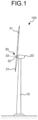
- FIG. 1 is a diagram illustrating an example of a wind power generation device 100 in which a blade 31 according to the present embodiment is used.
- the wind power generation device 100 includes a tower 10, a power generator 20, and a windmill 30.
- the tower 10 is installed on the ground or the like, for example, and supports the power generator 20 at a top part thereof.
- the power generator 20 includes a rotating shaft 21.
- the windmill 30 is attached to the rotating shaft of the power generator 20.
- the windmill 30 includes the blade 31, a hub 32, and a rotor 33. At least one blade 31 is disposed, and attached to the hub 32.
- the hub 32 is fixed to the rotor 33.
- the rotor 33 is supported to be able to rotate about a rotation center axis of the rotating shaft 21 as a center.
- the wind power generation device 100 converts rotational energy of the windmill 30 into electric energy when the blade 31 receives wind to rotate the rotor 33, and the power generator 20 is driven by rotation of the rotor 33.
- FIG. 2 is a schematic diagram illustrating a configuration of the blade 31.
- the blade 31 includes a blade main body 34.
- the blade main body 34 includes a blade root portion 34a and a blade front end portion 34b at both ends in a blade length direction, and includes a leading edge portion 34c and a trailing edge portion 34d at both ends in a blade chord direction.
- FIG. 3 is a diagram illustrating an enlarged view of part of the blade 31.
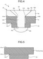
- FIG. 4 is a diagram illustrating a configuration along the A-A cross section in FIG. 3 .
- the blade 31 includes a blade member 41, a leading edge protector 42, a plate-shaped member 43, and a fastening member 44.
- the blade member 41 constitutes the blade main body 34.
- the blade member 41 is formed by using fiber-reinforced plastics and the like such as glass fiber-reinforced plastics and carbon fiber-reinforced plastics, for example.
- Blade members 41 are arranged to be opposed to each other on a back side and a belly side of the blade main body 34 to form a hollow space 35, and connected to each other at the leading edge portion 34c and the trailing edge portion 34d.
- a down conductor 36 is arranged in the hollow space 35 of the blade member 41.
- the down conductor 36 is formed by using a conductive material.
- the down conductor 36 constitutes at least part of an electric circuit through which a lightning current generated on the blade 31 flows when the blade 31 is struck by lightning.
- the down conductor 36 is arranged along the blade length direction inside the hollow space 35.
- One end of the down conductor 36 is connected to a chip receptor 37 arranged at the blade front end portion 34b, and the other end thereof is connected to a ground wire (not illustrated) that is disposed on the blade root portion 34a side.
- the leading edge protector 42 covers a surface 41a of the blade member 41 at the leading edge portion 34c of the blade main body 34.
- the leading edge protector 42 covers the leading edge portion 34c to protect the leading edge portion 34c against raindrops, dust, and the like, and suppress erosion damage of the blade main body 34.
- the leading edge protector 42 is formed by using a metallic material such as titanium, for example.
- the plate-shaped member 43 is arranged on a back surface 41b of the blade member 41 at the leading edge portion 34c of the blade main body 34.
- the plate-shaped member 43 is formed by using a resin material, for example.
- the plate-shaped member 43 is joined to the back surface 41b of the blade member 41 via an adhesive agent 43a formed of resin or the like.
- the adhesive agent 43a prevents the plate-shaped member 43 from peeling off from the back surface 41b.
- the adhesive agent 43a can be deformed to move the plate-shaped member 43 in the direction along the back surface 41b. In this way, the plate-shaped member 43 is arranged in a state in which movement thereof in a direction away from the back surface 41b is regulated and movement thereof in the direction along the back surface 41b is allowed.
- the fastening member 44 is disposed to pass through the leading edge protector 42, the blade member 41, and the plate-shaped member 43.
- the fastening member 44 fastens the leading edge protector 42, the blade member 41, and the plate-shaped member 43 by holding the leading edge protector 42 and the plate-shaped member 43.
- the fastening member 44 includes a head portion 44a, a fastener portion 44b, and a shaft portion 44c.
- the head portion 44a presses the leading edge protector 42 toward the blade member 41 side.
- the fastener portion 44b presses the plate-shaped member 43 toward the blade member 41 side.
- the shaft portion 44c passes through the leading edge protector 42, the blade member 41, and the plate-shaped member 43, and connects the head portion 44a with the fastener portion 44b.
- the fastening member 44 used is a blind fastener that can be deformed so that the diameter of the fastener portion 44b is increased by an operation from the leading edge protector 42 side, for example.
- a through hole 42c corresponding to the shape of the head portion 44a is formed on a surface 42a of the leading edge protector 42.
- the head portion 44a is housed in the through hole 42c to block the through hole 42c. Due to this, the head portion 44a is arranged in a state in which movement thereof in a direction along the surface 41a of the blade member 41 is regulated. This configuration can prevent a gap from being formed between the head portion 44a and an inner peripheral surface of the through hole 42c, and prevent raindrops, dust, and the like from entering the gap.
- the through hole 42c has a tapered shape the diameter of which is reduced in a direction from the surface 42a toward the back surface 42b on the blade member 41 side (hereinafter, referred to as a depth direction).
- the head portion 44a is arranged in a state of engaging with the through hole 42c in the depth direction.
- a through hole 41c having a larger diameter than the diameter of the shaft portion 44c is formed on the blade member 41.
- An inner peripheral surface of the through hole 41c is formed to have a gap 41d between itself and the shaft portion 44c.
- a through hole 43c having a diameter corresponding to the diameter of the shaft portion 44c is formed on the plate-shaped member 43.
- an outer peripheral surface of the shaft portion 44c is in a state of being supported by an inner peripheral surface of the through hole 43c.
- This configuration can prevent the fastener portion 44b from entering the through hole 43c in a case in which the diameter of the fastener portion 44b is increased. Due to this, the plate-shaped member 43 can be securely pressed toward the blade member 41 side by the fastener portion 44b. When the plate-shaped member 43 is arranged, the blade member 41 is not brought into contact with the fastener portion 44b. Due to this, in a case in which the blade member 41 is deformed, it is possible to prevent a load from being directly applied to the fastener portion 44b.
- FIG. 5 to FIG. 9 are diagrams illustrating examples of a process of manufacturing the blade 31.
- FIG. 10 is a flowchart illustrating an example of the method for manufacturing the blade 31.
- the plate-shaped member 43 is arranged on the back surface 41b of a portion corresponding to the leading edge portion 34c of a back side member 41p and a belly side member 41q constituting the blade member 41 (Step S10: FIG. 10 ).
- the through hole is formed on the plate-shaped member 43 in a later process, and the plate-shaped member 43 is held by the adhesive agent 43a not to peel off when being fastened by the fastening member 44.
- Step S20 the back side member 41p and the belly side member 41q of the blade member 41 are joined to form the blade main body 34 (Step S20: FIG. 10 ).
- the plate-shaped member 43 is housed in the hollow space 35 of the blade main body 34.
- the leading edge protector 42 is arranged on the surface 41a of the blade member 41 at the leading edge portion 34c of the blade main body 34 (Step S30: FIG. 10 ).
- the through holes 42c, 41c, and 43c are formed to pass through the leading edge protector 42, the blade member 41, and the plate-shaped member 43 (Step S40: FIG. 10 ).
- the diameter of the through hole 41c of the blade member 41 is formed to be larger than the diameter of the shaft portion 44c so that the gap 41d is formed between the blade member 41 and the shaft portion 44c in a case in which the fastening member 44 is arranged.
- the fastening member 44 is arranged.
- the shaft portion 44c of the fastening member 44 and the fastener portion 44b before the diameter of which is increased are inserted into the through holes 42c, 41c, and 43c in order.
- the diameter of the fastener portion 44b is increased by operating the head portion 44a of the fastening member 44 from an outer side of the hollow space 35.
- the fastener portion 44b presses the plate-shaped member 43 from the hollow space 35 side toward the blade member 41 side. Due to this, the fastening member 44 fastens the blade member 41 to the plate-shaped member 43 (Step S50: FIG. 10 ).
- the blade 31 includes the blade member 41 that forms the blade main body 34, the leading edge protector 42 that covers the surface 41a of the blade member 41 at the leading edge portion 34c of the blade main body 34, the plate-shaped member 43 that is arranged on the back surface 41b opposite to a surface covered by the leading edge protector 42 of the blade member 41, and the fastening member 44 that is disposed to pass through the leading edge protector 42, the blade member 41, and the plate-shaped member 43, and fastens the leading edge protector 42, the blade member 41, and the plate-shaped member 43 by holding the leading edge protector 42 and the plate-shaped member 43.
- the blade member 41 is formed to have the gap 41d between itself and the fastening member 44.
- the blade member 41 is formed to have the gap 41d between itself and the fastening member 44, so that, in a case in which the blade member 41 is deformed, deformation can be released to the gap 41d, and the blade member 41 can be prevented from applying force in a direction of shearing the fastening member 44.
- the blade member 41 is fastened to the fastening member 44 via the plate-shaped member 43, so that the blade member 41 is not brought into contact with the fastener portion 44b as a fastening portion of the fastening member 44. Due to this, in a case in which the blade member 41 is deformed, it is possible to prevent a load from being directly applied to the fastener portion 44b. Accordingly, the leading edge protector 42 can be appropriately fastened to the leading edge portion 34c of the blade main body 34.
- the plate-shaped member 43 is arranged in a state in which movement thereof in a direction away from the back surface 41b is regulated. Accordingly, in a case in which the fastening member 44 is arranged, for example, the plate-shaped member 43 can be prevented from peeling off.
- the plate-shaped member 43 is arranged in a state in which movement thereof in a direction along the back surface 41b is allowed. Accordingly, in a case in which the blade member 41 is deformed, when the plate-shaped member 43 moves in the direction along the back surface 41b between the blade member 41 and the fastening member 44, part of the force working on the fastening member 44 from the blade member 41 can be released.
- the plate-shaped member 43 is formed of a resin material. Accordingly, when fastening is performed with the fastening member 44, the resin material is compressed and bent to cause relaxation. Due to this relaxation, fastening force of the fastening member 44 is relieved, so that a shearing load can be prevented from being applied to the shaft portion 44c.
- the fastening member 44 includes the head portion 44a that presses the leading edge protector 42 toward the blade member 41 side, the fastener portion 44b that presses the plate-shaped member 43 toward the blade member 41 side, and the shaft portion 44c that passes through the leading edge protector 42, the blade member 41, and the plate-shaped member 43 to connect the head portion 44a with the fastener portion 44b. Accordingly, the head portion 44a and the fastener portion 44b can securely hold the leading edge protector 42 and the plate-shaped member 43 therebetween, so that the leading edge protector 42 can be appropriately fastened to the blade member 41.
- the fastening member 44 is arranged in a state in which movement of the head portion 44a in a direction along the surface 41a of the blade member 41 is regulated.
- This configuration can prevent a gap from being formed between the head portion 44a and an inner peripheral surface of the through hole 42c, and prevent raindrops, dust, and the like from entering the gap.
- the fastening member 44 is a blind fastener that can be deformed so that the diameter of the fastener portion 44b is increased by an operation from the leading edge protector 42 side.
- fastening can be performed with the fastening member 44 after the blade members 41 are bonded to configure the blade main body 34.
- the method for manufacturing the blade 31 includes a step of arranging the leading edge protector 42 that covers the surface 41a of the blade member 41 on the leading edge portion 34c of the blade main body 34 that is formed by using the blade member 41, a step of arranging the plate-shaped member 43 on the back surface 41b as a surface of the blade member 41 on the back side of the leading edge protector 42, a step of forming the through hole passing through the leading edge protector 42, the blade member 41, and the plate-shaped member 43, and a step of inserting the fastening member 44 into the through hole to fasten the leading edge protector 42, the blade member 41, and the plate-shaped member 43.
- the through hole is formed to have the gap 41d between the leading edge protector 42 and the outer peripheral surface of the fastening member 44 in a case in which the fastening member 44 is arranged.
- FIG. 11 is a diagram illustrating an example of a blade 131 according to the second embodiment.
- the blade 131 illustrated in FIG. 11 is different from the first embodiment in that the blade 131 includes a plate-shaped member 143 that is formed by using a metallic material.
- the plate-shaped member 143 formed of a metallic material is disposed on the blade 131 according to the present embodiment, so that relaxation is hardly caused in a case in which fastening is performed with the fastening member 44.
- force working on the fastening member 44 can be released by the plate-shaped member 143 in a case in which the blade member 41 is deformed while maintaining fastening force of the fastening member 44.
- FIG. 12 is a diagram illustrating an example of a blade 231 according to the third embodiment.
- the blade 231 illustrated in FIG. 12 has a configuration in which the plate-shaped member 43 is not joined to the blade member 41, and a supporting member 45 and an elastic member 46 are further provided.
- a supporting member 45 and an elastic member 46 are further provided.
- another member that is plastically deformed with a predetermined load may be disposed, for example, in place of the elastic member 46.
- the supporting member 45 includes a side wall portion 45a and a projecting portion 45b.
- the side wall portion 45a is joined to the back surface 41b of the blade member 41.
- the side wall portion 45a surrounds an outer peripheral part of the plate-shaped member 43 in a direction along the back surface 41b.
- the projecting portion 45b projects from the side wall portion 45a toward the plate-shaped member 43 side to support the plate-shaped member 43.
- the projecting portion 45b regulates movement of the plate-shaped member 43 in a direction away from the back surface 41b of the blade member 41.
- the elastic member 46 is arranged between the side wall portion 45a and the plate-shaped member 43.
- the elastic member 46 is in contact with at least part of the outer peripheral part of the plate-shaped member 43 in a direction along the back surface 41b.
- the elastic member 46 for example, foam or the like is used.
- the elastic member 46 is elastically deformed to allow movement thereof.
- the elastic member 46 prevents the plate-shaped member 43 from shifting in a direction along the back surface 41b in a case in which no force works on the plate-shaped member 43 from the blade member 41 side.
- the blade 231 according to the present embodiment further includes the supporting member 45 that surrounds the outer peripheral part of the plate-shaped member 43 in the direction along the back surface 41b, and at least part of the supporting member 45 projects toward the plate-shaped member 43 side to regulate movement of the plate-shaped member 43 in a direction away from the back surface 41b.
- the plate-shaped member 43 can be easily moved in a direction along the back surface 41b.
- the blade 231 according to the present embodiment further includes the elastic member that is in contact with at least part of the outer peripheral part of the plate-shaped member 43 in a direction along the back surface 41b, and elastically deformed to allow movement of the plate-shaped member 43 when the plate-shaped member 43 moves in a direction along the back surface 41b.
- the elastic member can be elastically deformed to allow the movement. Additionally, it is possible to prevent the plate-shaped member 43 from shifting in a direction along the back surface 41b in a case in which no force works on the plate-shaped member 43 from the blade member 41 side.
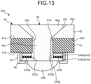
- FIG. 13 is a diagram illustrating an example of a blade 331 according to the fourth embodiment.
- the blade 331 illustrated in FIG. 13 is different from the configuration of the blade 231 according to the third embodiment in that a plurality of plate-shaped members 243 are disposed in a laminated state, and other configurations are the same as those of the blade 231 according to the third embodiment.
- the plate-shaped members 243 are formed by using a resin material or a metallic material, for example. In the present embodiment, the two plate-shaped members 243 are arranged. Hereinafter, in a case of distinguishing the two plate-shaped members 243 from each other, they are referred to as plate-shaped members 243a and 243b.
- the plate-shaped member 243a is joined to the back surface 41b of the blade member 41.
- a through hole 243c through which the shaft portion 44c of the fastening member 44 passes is formed on the plate-shaped member 243a.
- the through hole 243c is formed to have a larger diameter than the diameter of the shaft portion 44c, for example, so that a gap is formed between the plate-shaped member 243a and the shaft portion 44c.
- the plate-shaped member 243b is arranged on the hollow space 35 side with respect to the plate-shaped member 243a.
- the plate-shaped member 243b is disposed in a state of being supported by the projecting portion 45b of the supporting member 45.
- a through hole 243d through which the shaft portion 44c passes is formed on the plate-shaped member 243b.
- the through hole 243d is formed to have a smaller diameter than that of the fastener portion 44b so that the fastener portion 44b of the fastening member 44 does not enter the through hole 243d.
- Each of the plate-shaped member 243a and the plate-shaped member 243b is formed by using a resin material, a metallic material, or the like having high rigidity.
- the plate-shaped member 243a and the plate-shaped member 243b respectively include sliding layers 243e and 243f on opposing surfaces.
- the sliding layers 243e and 243f are formed in a plate shape by using a material having a low friction coefficient such as polytetrafluoroethylene (PTFE) or carbon, for example.
- PTFE polytetrafluoroethylene
- the sliding layer 243e is joined to the plate-shaped member 243a.
- the sliding layer 243f is joined to the plate-shaped member 243b.
- the plate-shaped member 243a and the plate-shaped member 243b can be slid along the back surface 41b by the sliding layers 243e and 243f while securing the rigidity of the plate-shaped members 243a and 243b.
- the plate-shaped member 243b is formed so that a surface 243g in contact with the fastener portion 44b is a rough surface. With this configuration, frictional force is generated between the fastener portion 44b and the plate-shaped member 243b. Due to this frictional force, the fastener portion 44b and the plate-shaped member 243b are integrally slid as much as possible.
- the plate-shaped members 243 are disposed in a laminated state.
- the plate-shaped members 243 can successively move to efficiently release the force from the blade member 41 side.
- the plate-shaped members 243 respectively include the sliding layers 243e and 243f on the opposing surfaces.
- the plate-shaped members 243 by sliding the plate-shaped members 243 by the sliding layers 243e and 243f, relative movement of the plate-shaped members 243 can be easily caused. Due to this, the force from the blade member 41 can be efficiently released.
- the plate-shaped member 243b is formed so that the surface 243g in contact with the fastener portion 44b is a rough surface. With this configuration, frictional force can be generated between the fastener portion 44b and the plate-shaped member 243b, and the fastener portion 44b and the plate-shaped member 243b can be integrally slid as much as possible by this frictional force.
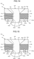
- FIG. 14 is a diagram illustrating an example of a blade 431 according to the fifth embodiment.
- a fastening member 444 is a bolt-nut mechanism in which a shaft portion 444c is screw-joined to a fastener portion 444b.
- a plate-shaped member 443 is a nut plate.
- Other configurations are the same as those of the blade 31 according to the first embodiment.
- the plate-shaped member 443 includes a plate member 443a, a bolt 443b for fixing, and a slider 443c.
- the plate member 443a is formed in a plate shape using a metallic material, for example.
- the plate member 443a is fixed to the back surface 41b of the blade member 41 with the bolt 443b for fixing.
- the plate member 443a has an opening 443d passing therethrough in a thickness direction.
- the slider 443c is arranged across the opening 443d of the plate member 443a, and disposed to be movable with respect to the plate member 443a.
- the slider 443c has a through hole 443e through which the shaft portion 444c of the fastening member 444 passes.
- the fastening member 444 is arranged so that the shaft portion 444c passes through the opening 443d of the plate member 443a and the through hole 443e of the slider 443c.
- the fastener portion 444b is screw-joined from an end part of the shaft portion 444c, and is fastened by pressing the slider 443c toward the plate member 443a side. Force for pressing the plate member 443a by the slider 443c can be adjusted by adjusting screw-joining between the fastener portion 444b and the shaft portion 444c.
- the fastening member 444 is the bolt-nut mechanism in which the shaft portion 444c is screw-joined to the fastener portion 444b
- the plate-shaped member 443 is the nut plate including the plate member 443a that has the opening 443d and the slider 443c that is arranged across the opening 443d and can move relatively to the plate member 443a.
- FIG. 15 is a diagram illustrating an example of a blade 531 according to the sixth embodiment.
- the plate member 443a and the bolt 443b for fixing can relatively move in a direction along the back surface 41b of the blade member 41.
- Other configurations are the same as those of the blade 431 according to the fifth embodiment.
- a gap 443f is formed between the plate member 443a and the bolt 443b for fixing. Due to this gap 443f, in the plate-shaped member 443, the plate member 443a and the bolt 443b for fixing can relatively move. Thus, at the time when the force from the blade member 41 is transmitted to the plate member 443a in a case in which the blade member 41 is deformed, the plate member 443a can move in a direction along the back surface 41b with respect to the blade member 41. Due to this movement, in a case in which the blade member 41 is deformed, it is possible to more efficiently prevent a load from being directly applied to the fastener portion 444b.
- the blade 31 includes the blade member 41 forming the blade main body 34 that rotates integrally with the rotor 33, the leading edge protector 42 that covers the surface 41a of the blade member 41 at the leading edge portion 34c of the blade main body 34, the plate-shaped member 43 that is arranged on the back surface 41b of a surface covered by the leading edge protector 42 of the blade member 41, and the fastening member 44 that is disposed to pass through the leading edge protector 42, the blade member 41, and the plate-shaped member 43, and fastens the leading edge protector 42, the blade member 41, and the plate-shaped member 43 by holding the leading edge protector 42 and the plate-shaped member 43.
- the blade member 41 is formed to have the gap 41d between itself and the fastening member 44.
- the blade member 41 is formed to have the gap 41d between itself and the fastening member 44, so that, in a case in which the blade member 41 is deformed, deformation can be released to the gap 41d, and the blade member 41 can be prevented from applying force in a direction of shearing the fastening member 44.
- the blade member 41 is fastened to the fastening member 44 via the plate-shaped member 43, so that the blade member 41 is not brought into contact with the fastener portion 44b as a fastening portion of the fastening member 44. Due to this, in a case in which the blade member 41 is deformed, it is possible to prevent a load from being directly applied to the fastener portion 44b. Accordingly, the leading edge protector 42 can be appropriately fastened to the leading edge portion 34c of the blade main body 34.
- the plate-shaped member 43 is arranged in a state in which movement thereof in a direction away from the back surface 41b is regulated. Accordingly, in a case in which the fastening member 44 is arranged, for example, the plate-shaped member 43 can be prevented from peeling off.
- the blade 231 according to the third embodiment further includes the supporting member 45 that surrounds the outer peripheral part of the plate-shaped member 43 in the direction along the back surface 41b, and at least part of the supporting member 45 projects toward the plate-shaped member 43 side to regulate movement of the plate-shaped member 43 in a direction away from the back surface 41b.
- the plate-shaped member 43 can be easily moved in a direction along the back surface 41b.
- the plate-shaped member 43 is arranged in a state in which movement thereof in a direction along the back surface 41b is allowed. Accordingly, in a case in which the blade member 41 is deformed, when the plate-shaped member 43 moves in the direction along the back surface 41b between the blade member 41 and the fastening member 44, part of the force working on the fastening member 44 from the blade member 41 can be released.
- the blade 231 according to the third embodiment further includes the elastic member that is in contact with at least part of the outer peripheral part of the plate-shaped member 43 in a direction along the back surface 41b, and elastically deformed to allow movement of the plate-shaped member 43 when the plate-shaped member 43 moves in a direction along the back surface 41b.
- the elastic member can be elastically deformed to allow the movement. Additionally, it is possible to prevent the plate-shaped member 43 from shifting in a direction along the back surface 41b in a case in which no force works on the plate-shaped member 43 from the blade member 41 side.
- the plate-shaped member 43 is formed of a resin material. Accordingly, when fastening is performed with the fastening member 44, the resin material is compressed and bent to cause relaxation. Due to this relaxation, fastening force of the fastening member 44 is relieved, so that a shearing load can be prevented from being applied to the shaft portion 44c.
- the plate-shaped member 143 formed of a metallic material is disposed in the blade 131 according to the second embodiment, so that relaxation is hardly caused in a case in which fastening is performed with the fastening member 44.
- force working on the fastening member 44 can be released by the plate-shaped member 143 in a case in which the blade member 41 is deformed while maintaining fastening force of the fastening member 44.
- the plate-shaped members 243 are disposed in a laminated state. Thus, at the time when the blade member 41 is deformed, the plate-shaped members 243 can successively move to efficiently release the force from the blade member 41 side.
- the plate-shaped members 243 respectively include the sliding layers 243e and 243f on the opposing surfaces.
- the plate-shaped members 243 by sliding the plate-shaped members 243 by the sliding layers 243e and 243f, relative movement of the plate-shaped members 243 can be easily caused. Due to this, the force from the blade member 41 can be efficiently released.
- the fastening member 44 includes the head portion 44a that presses the leading edge protector 42 toward the blade member 41 side, the fastener portion 44b that presses the plate-shaped member 43 toward the blade member 41 side, and the shaft portion 44c that passes through the leading edge protector 42, the blade member 41, and the plate-shaped member 43 to connect the head portion 44a with the fastener portion 44b. Accordingly, the head portion 44a and the fastener portion 44b can securely hold the leading edge protector 42 and the plate-shaped member 43 therebetween, so that the leading edge protector 42 can be appropriately fastened to the blade member 41.
- the fastening member 44 is arranged in a state in which movement of the head portion 44a in a direction along the surface 41a of the blade member 41 is regulated.
- This configuration can prevent a gap from being formed between the head portion 44a and an inner peripheral surface of the through hole 42c, and prevent raindrops, dust, and the like from entering the gap.
- the fastening member 44 is a blind fastener that can be deformed so that the diameter of the fastener portion 44b is increased by an operation from the leading edge protector 42 side.
- fastening can be performed with the fastening member 44 after the blade members 41 are bonded to configure the blade main body 34.
- the plate-shaped member 243b is formed so that the surface 243g in contact with the fastener portion 44b is a rough surface. With this configuration, frictional force can be generated between the fastener portion 44b and the plate-shaped member 243b, and the fastener portion 44b and the plate-shaped member 243b can be integrally slid as much as possible by this frictional force.
- the fastening member 444 is the bolt-nut mechanism in which the shaft portion 444c is screw-joined to the fastener portion 444b
- the plate-shaped member 443 is the nut plate including the plate member 443a that has the opening 443d and the slider 443c that is arranged across the opening 443d and can move relatively to the plate member 443a.
- the gap 443f is formed between the plate member 443a and the bolt 443b for fixing. Due to this gap 443f, in the plate-shaped member 443, the plate member 443a and the bolt 443b for fixing can relatively move. Thus, at the time when the force from the blade member 41 is transmitted to the plate member 443a in a case in which the blade member 41 is deformed, the plate member 443a can move in a direction along the back surface 41b with respect to the blade member 41. Due to this movement, in a case in which the blade member 41 is deformed, it is possible to more efficiently prevent a load from being directly applied to the fastener portion 444b.
- the method for manufacturing the blade 31 according to the first embodiment includes a step of arranging the leading edge protector 42 that covers the surface 41a of the blade member 41 on the leading edge portion 34c of the blade main body 34 that is formed by using the blade member 41, a step of arranging the plate-shaped member 43 on the back surface 41b as a surface of the blade member 41 on the back side of the leading edge protector 42, a step of forming the through hole passing through the leading edge protector 42, the blade member 41, and the plate-shaped member 43, and a step of inserting the fastening member 44 into the through hole to fasten the leading edge protector 42, the blade member 41, and the plate-shaped member 43.
- the through hole is formed to have the gap 41d between the leading edge protector 42 and the outer peripheral surface of the fastening member 44 in a case in which the fastening member 44 is arranged.
- a technical scope of the present invention is not limited to the embodiments described above, and can be appropriately modified without departing from the gist of the present invention.
- the blade 31 used for the wind power generation device 100 is exemplified in the embodiments described above, but the embodiment is not limited thereto.
- the description of the embodiments described above can also be applied to other blades such as a blade of an aircraft or a blade used for a propeller of a helicopter (rotor blade), for example, a turbine blade of an engine, a gas turbine, or a steam turbine, a blade used for a blower and the like in a power generation plant, a chemical plant, and the like.
Landscapes
- Engineering & Computer Science (AREA)
- Mechanical Engineering (AREA)
- General Engineering & Computer Science (AREA)
- Life Sciences & Earth Sciences (AREA)
- Sustainable Development (AREA)
- Sustainable Energy (AREA)
- Chemical & Material Sciences (AREA)
- Combustion & Propulsion (AREA)
- Architecture (AREA)
- Wind Motors (AREA)
Abstract
Description
- The present disclosure relates to a blade and a method for manufacturing the blade.
- On a blade that is disposed on a windmill or the like used for a wind power generation device, erosion damage is caused when raindrops, dust, and the like repeatedly collide with a leading edge portion thereof. To suppress such erosion damage, there is known a configuration in which a leading edge protector is arranged on the leading edge portion of the blade (for example, refer to Patent Literature 1).
- Patent Literature 1:
WO2018/219524 - The leading edge protector described above is attached to the leading edge portion of the blade with an adhesive agent, for example. Additionally, mechanical fastening may also be used to prevent the adhesive agent from peeling off and the leading edge protector from falling off. On the other hand, the blade is largely deformed, so that relative deformation may be caused between the leading edge protector and the blade, and a fastening portion may be damaged.
- The present disclosure has been made in view of such a situation, and provides a blade in which a leading edge protector can be appropriately fastened to a leading edge portion and a method for manufacturing the blade. Solution to Problem
- A blade according to the present disclosure includes: a blade member that forms a blade main body; a leading edge protector that covers a surface of the blade member at a leading edge portion of the blade main body; a plate-shaped member that is arranged on a back surface opposite to a surface of the blade member covered by the leading edge protector; and a fastening member that is disposed to pass through the leading edge protector, the blade member, and the plate-shaped member, and fastens the leading edge protector, the blade member, and the plate-shaped member by holding the leading edge protector and the plate-shaped member. The blade member is formed to have a gap between the blade member and the fastening member.
- A method for manufacturing a blade according to the present disclosure includes the steps of: arranging a leading edge protector that covers a surface of a blade member on a leading edge portion of a blade main body that is formed by using the blade member; arranging a plate-shaped member on a back surface opposite to a surface covered by the leading edge protector of the blade member; forming a through hole passing through the leading edge protector, the blade member, and the plate-shaped member; and inserting a fastening member into the through hole to fasten the leading edge protector, the blade member, and the plate-shaped member. The step of forming the through hole includes forming the through hole to have a gap between the leading edge protector and the fastening member in a case in which the fastening member is arranged. Advantageous Effects of Invention
- The present disclosure can provide a blade in which a leading edge protector can be appropriately fastened to a leading edge portion and a method for manufacturing the blade.
-
-
FIG. 1 is a diagram illustrating an example of a wind power generation device in which a blade according to the present embodiment is used. -
FIG. 2 is a schematic diagram illustrating a configuration of the blade. -
FIG. 3 is a diagram illustrating an enlarged view of part of the blade. -
FIG. 4 is a diagram illustrating a configuration along the A-A cross section inFIG. 3 . -
FIG. 5 is a diagram illustrating an example of a manufacturing process of the blade. -
FIG. 6 is a diagram illustrating an example of the manufacturing process of the blade. -
FIG. 7 is a diagram illustrating an example of the manufacturing process of the blade. -
FIG. 8 is a diagram illustrating an example of the manufacturing process of the blade. -
FIG. 9 is a diagram illustrating an example of the manufacturing process of the blade. -
FIG. 10 is a flowchart illustrating an example of a method for manufacturing the blade. -
FIG. 11 is a diagram illustrating an example of a blade according to a second embodiment. -
FIG. 12 is a diagram illustrating an example of a blade according to a third embodiment. -
FIG. 13 is a diagram illustrating an example of a blade according to a fourth embodiment. -
FIG. 14 is a diagram illustrating an example of a blade according to a fifth embodiment. -
FIG. 15 is a diagram illustrating an example of a blade according to a sixth embodiment. - The following describes embodiments of a blade and a method for manufacturing the blade according to the present disclosure based on the drawings. The present invention is not limited to the embodiments. Constituent elements in the embodiments described below encompass a constituent element that can be easily replaced by those skilled in the art, or substantially the same constituent element. The present embodiment exemplifies a blade used for a wind power generation device, but the embodiment is not limited thereto. In another embodiment, the blade may be a blade of an aircraft or a blade of a helicopter (rotor blade). In still another embodiment, the blade may be a turbine blade of an engine, a gas turbine, or a steam turbine. In yet another embodiment, the blade may be a blade used for a blower or the like in a power generation plant, a chemical plant, and the like.
-
FIG. 1 is a diagram illustrating an example of a windpower generation device 100 in which ablade 31 according to the present embodiment is used. As illustrated inFIG. 1 , the windpower generation device 100 includes atower 10, apower generator 20, and awindmill 30. Thetower 10 is installed on the ground or the like, for example, and supports thepower generator 20 at a top part thereof. Thepower generator 20 includes a rotating shaft 21. Thewindmill 30 is attached to the rotating shaft of thepower generator 20. Thewindmill 30 includes theblade 31, ahub 32, and arotor 33. At least oneblade 31 is disposed, and attached to thehub 32. Thehub 32 is fixed to therotor 33. Therotor 33 is supported to be able to rotate about a rotation center axis of the rotating shaft 21 as a center. The windpower generation device 100 converts rotational energy of thewindmill 30 into electric energy when theblade 31 receives wind to rotate therotor 33, and thepower generator 20 is driven by rotation of therotor 33. -
FIG. 2 is a schematic diagram illustrating a configuration of theblade 31. As illustrated inFIG. 2 , theblade 31 includes a blademain body 34. The blademain body 34 includes ablade root portion 34a and a bladefront end portion 34b at both ends in a blade length direction, and includes a leadingedge portion 34c and atrailing edge portion 34d at both ends in a blade chord direction.FIG. 3 is a diagram illustrating an enlarged view of part of theblade 31.FIG. 4 is a diagram illustrating a configuration along the A-A cross section inFIG. 3 . As illustrated inFIG. 2 andFIG. 3 , theblade 31 includes ablade member 41, a leadingedge protector 42, a plate-shaped member 43, and afastening member 44. - The
blade member 41 constitutes the blademain body 34. Theblade member 41 is formed by using fiber-reinforced plastics and the like such as glass fiber-reinforced plastics and carbon fiber-reinforced plastics, for example.Blade members 41 are arranged to be opposed to each other on a back side and a belly side of the blademain body 34 to form ahollow space 35, and connected to each other at the leadingedge portion 34c and thetrailing edge portion 34d. - A
down conductor 36 is arranged in thehollow space 35 of theblade member 41. Thedown conductor 36 is formed by using a conductive material. The downconductor 36 constitutes at least part of an electric circuit through which a lightning current generated on theblade 31 flows when theblade 31 is struck by lightning. The downconductor 36 is arranged along the blade length direction inside thehollow space 35. One end of thedown conductor 36 is connected to achip receptor 37 arranged at the bladefront end portion 34b, and the other end thereof is connected to a ground wire (not illustrated) that is disposed on theblade root portion 34a side. - The
leading edge protector 42 covers asurface 41a of theblade member 41 at theleading edge portion 34c of the blademain body 34. Theleading edge protector 42 covers theleading edge portion 34c to protect theleading edge portion 34c against raindrops, dust, and the like, and suppress erosion damage of the blademain body 34. Theleading edge protector 42 is formed by using a metallic material such as titanium, for example. - The plate-shaped
member 43 is arranged on aback surface 41b of theblade member 41 at theleading edge portion 34c of the blademain body 34. The plate-shapedmember 43 is formed by using a resin material, for example. The plate-shapedmember 43 is joined to theback surface 41b of theblade member 41 via anadhesive agent 43a formed of resin or the like. Theadhesive agent 43a prevents the plate-shapedmember 43 from peeling off from theback surface 41b. Additionally, in a case in which force in a direction along theback surface 41b works on the plate-shapedmember 43, for example, theadhesive agent 43a can be deformed to move the plate-shapedmember 43 in the direction along theback surface 41b. In this way, the plate-shapedmember 43 is arranged in a state in which movement thereof in a direction away from theback surface 41b is regulated and movement thereof in the direction along theback surface 41b is allowed. - The
fastening member 44 is disposed to pass through theleading edge protector 42, theblade member 41, and the plate-shapedmember 43. Thefastening member 44 fastens theleading edge protector 42, theblade member 41, and the plate-shapedmember 43 by holding theleading edge protector 42 and the plate-shapedmember 43. Thefastening member 44 includes ahead portion 44a, afastener portion 44b, and ashaft portion 44c. Thehead portion 44a presses theleading edge protector 42 toward theblade member 41 side. Thefastener portion 44b presses the plate-shapedmember 43 toward theblade member 41 side. Theshaft portion 44c passes through theleading edge protector 42, theblade member 41, and the plate-shapedmember 43, and connects thehead portion 44a with thefastener portion 44b. In the present embodiment, as thefastening member 44, used is a blind fastener that can be deformed so that the diameter of thefastener portion 44b is increased by an operation from theleading edge protector 42 side, for example. - As illustrated in
FIG. 4 , a throughhole 42c corresponding to the shape of thehead portion 44a is formed on asurface 42a of theleading edge protector 42. Thehead portion 44a is housed in the throughhole 42c to block the throughhole 42c. Due to this, thehead portion 44a is arranged in a state in which movement thereof in a direction along thesurface 41a of theblade member 41 is regulated. This configuration can prevent a gap from being formed between thehead portion 44a and an inner peripheral surface of the throughhole 42c, and prevent raindrops, dust, and the like from entering the gap. In the present embodiment, the throughhole 42c has a tapered shape the diameter of which is reduced in a direction from thesurface 42a toward theback surface 42b on theblade member 41 side (hereinafter, referred to as a depth direction). Thehead portion 44a is arranged in a state of engaging with the throughhole 42c in the depth direction. - A through hole 41c having a larger diameter than the diameter of the
shaft portion 44c is formed on theblade member 41. An inner peripheral surface of the through hole 41c is formed to have agap 41d between itself and theshaft portion 44c. By disposing thisgap 41d, in a case in which theblade member 41 is deformed, deformation can be released to thegap 41d. That is, in a case in which theblade member 41 is deformed, theblade member 41 can be prevented from applying force in a direction of shearing theshaft portion 44c. - A through
hole 43c having a diameter corresponding to the diameter of theshaft portion 44c is formed on the plate-shapedmember 43. For example, an outer peripheral surface of theshaft portion 44c is in a state of being supported by an inner peripheral surface of the throughhole 43c. This configuration can prevent thefastener portion 44b from entering the throughhole 43c in a case in which the diameter of thefastener portion 44b is increased. Due to this, the plate-shapedmember 43 can be securely pressed toward theblade member 41 side by thefastener portion 44b. When the plate-shapedmember 43 is arranged, theblade member 41 is not brought into contact with thefastener portion 44b. Due to this, in a case in which theblade member 41 is deformed, it is possible to prevent a load from being directly applied to thefastener portion 44b. - Next, the following describes a method for manufacturing the
blade 31 described above.FIG. 5 to FIG. 9 are diagrams illustrating examples of a process of manufacturing theblade 31.FIG. 10 is a flowchart illustrating an example of the method for manufacturing theblade 31. First, as illustrated inFIG. 5 , the plate-shapedmember 43 is arranged on theback surface 41b of a portion corresponding to theleading edge portion 34c of aback side member 41p and abelly side member 41q constituting the blade member 41 (Step S10:FIG. 10 ). The through hole is formed on the plate-shapedmember 43 in a later process, and the plate-shapedmember 43 is held by theadhesive agent 43a not to peel off when being fastened by thefastening member 44. - Next, as illustrated in
FIG. 6 , theback side member 41p and thebelly side member 41q of theblade member 41 are joined to form the blade main body 34 (Step S20:FIG. 10 ). With this configuration, the plate-shapedmember 43 is housed in thehollow space 35 of the blademain body 34. - Next, as illustrated in
FIG. 7 , the leadingedge protector 42 is arranged on thesurface 41a of theblade member 41 at theleading edge portion 34c of the blade main body 34 (Step S30:FIG. 10 ). - Next, as illustrated in
FIG. 8 , the throughholes leading edge protector 42, theblade member 41, and the plate-shaped member 43 (Step S40:FIG. 10 ). In this case, the diameter of the through hole 41c of theblade member 41 is formed to be larger than the diameter of theshaft portion 44c so that thegap 41d is formed between theblade member 41 and theshaft portion 44c in a case in which thefastening member 44 is arranged. - Next, as illustrated in
FIG. 9 , thefastening member 44 is arranged. For example, theshaft portion 44c of thefastening member 44 and thefastener portion 44b before the diameter of which is increased are inserted into the throughholes fastener portion 44b passes through the throughhole 43c and reaches thehollow space 35, the diameter of thefastener portion 44b is increased by operating thehead portion 44a of thefastening member 44 from an outer side of thehollow space 35. When the diameter of thefastener portion 44b is increased, thefastener portion 44b presses the plate-shapedmember 43 from thehollow space 35 side toward theblade member 41 side. Due to this, thefastening member 44 fastens theblade member 41 to the plate-shaped member 43 (Step S50:FIG. 10 ). - As described above, the
blade 31 according to the present embodiment includes theblade member 41 that forms the blademain body 34, the leadingedge protector 42 that covers thesurface 41a of theblade member 41 at theleading edge portion 34c of the blademain body 34, the plate-shapedmember 43 that is arranged on theback surface 41b opposite to a surface covered by the leadingedge protector 42 of theblade member 41, and thefastening member 44 that is disposed to pass through theleading edge protector 42, theblade member 41, and the plate-shapedmember 43, and fastens theleading edge protector 42, theblade member 41, and the plate-shapedmember 43 by holding theleading edge protector 42 and the plate-shapedmember 43. Theblade member 41 is formed to have thegap 41d between itself and thefastening member 44. - With this configuration, the
blade member 41 is formed to have thegap 41d between itself and thefastening member 44, so that, in a case in which theblade member 41 is deformed, deformation can be released to thegap 41d, and theblade member 41 can be prevented from applying force in a direction of shearing thefastening member 44. Theblade member 41 is fastened to thefastening member 44 via the plate-shapedmember 43, so that theblade member 41 is not brought into contact with thefastener portion 44b as a fastening portion of thefastening member 44. Due to this, in a case in which theblade member 41 is deformed, it is possible to prevent a load from being directly applied to thefastener portion 44b. Accordingly, the leadingedge protector 42 can be appropriately fastened to theleading edge portion 34c of the blademain body 34. - In the
blade 31 according to the present embodiment, the plate-shapedmember 43 is arranged in a state in which movement thereof in a direction away from theback surface 41b is regulated. Accordingly, in a case in which thefastening member 44 is arranged, for example, the plate-shapedmember 43 can be prevented from peeling off. - In the
blade 31 according to the present embodiment, the plate-shapedmember 43 is arranged in a state in which movement thereof in a direction along theback surface 41b is allowed. Accordingly, in a case in which theblade member 41 is deformed, when the plate-shapedmember 43 moves in the direction along theback surface 41b between theblade member 41 and thefastening member 44, part of the force working on thefastening member 44 from theblade member 41 can be released. - In the
blade 31 according to the present embodiment, the plate-shapedmember 43 is formed of a resin material. Accordingly, when fastening is performed with thefastening member 44, the resin material is compressed and bent to cause relaxation. Due to this relaxation, fastening force of thefastening member 44 is relieved, so that a shearing load can be prevented from being applied to theshaft portion 44c. - In the
blade 31 according to the present embodiment, thefastening member 44 includes thehead portion 44a that presses theleading edge protector 42 toward theblade member 41 side, thefastener portion 44b that presses the plate-shapedmember 43 toward theblade member 41 side, and theshaft portion 44c that passes through theleading edge protector 42, theblade member 41, and the plate-shapedmember 43 to connect thehead portion 44a with thefastener portion 44b. Accordingly, thehead portion 44a and thefastener portion 44b can securely hold theleading edge protector 42 and the plate-shapedmember 43 therebetween, so that theleading edge protector 42 can be appropriately fastened to theblade member 41. - In the
blade 31 according to the present embodiment, thefastening member 44 is arranged in a state in which movement of thehead portion 44a in a direction along thesurface 41a of theblade member 41 is regulated. This configuration can prevent a gap from being formed between thehead portion 44a and an inner peripheral surface of the throughhole 42c, and prevent raindrops, dust, and the like from entering the gap. - In the
blade 31 according to the present embodiment, thefastening member 44 is a blind fastener that can be deformed so that the diameter of thefastener portion 44b is increased by an operation from theleading edge protector 42 side. Thus, fastening can be performed with thefastening member 44 after theblade members 41 are bonded to configure the blademain body 34. - The method for manufacturing the
blade 31 according to the present embodiment includes a step of arranging theleading edge protector 42 that covers thesurface 41a of theblade member 41 on theleading edge portion 34c of the blademain body 34 that is formed by using theblade member 41, a step of arranging the plate-shapedmember 43 on theback surface 41b as a surface of theblade member 41 on the back side of theleading edge protector 42, a step of forming the through hole passing through theleading edge protector 42, theblade member 41, and the plate-shapedmember 43, and a step of inserting thefastening member 44 into the through hole to fasten theleading edge protector 42, theblade member 41, and the plate-shapedmember 43. At the step of forming the through hole, the through hole is formed to have thegap 41d between theleading edge protector 42 and the outer peripheral surface of thefastening member 44 in a case in which thefastening member 44 is arranged. Thus, it is possible to efficiently manufacture theblade 31 having the configuration in which theleading edge protector 42 is appropriately fastened to theleading edge portion 34c of the blademain body 34. - Next, the following describes a second embodiment of the present disclosure.
FIG. 11 is a diagram illustrating an example of ablade 131 according to the second embodiment. Theblade 131 illustrated inFIG. 11 is different from the first embodiment in that theblade 131 includes a plate-shapedmember 143 that is formed by using a metallic material. - The plate-shaped
member 143 formed of a metallic material is disposed on theblade 131 according to the present embodiment, so that relaxation is hardly caused in a case in which fastening is performed with thefastening member 44. Thus, force working on thefastening member 44 can be released by the plate-shapedmember 143 in a case in which theblade member 41 is deformed while maintaining fastening force of thefastening member 44. - Next, the following describes a third embodiment of the present disclosure.
FIG. 12 is a diagram illustrating an example of ablade 231 according to the third embodiment. Theblade 231 illustrated inFIG. 12 has a configuration in which the plate-shapedmember 43 is not joined to theblade member 41, and a supportingmember 45 and anelastic member 46 are further provided. Alternatively, another member that is plastically deformed with a predetermined load may be disposed, for example, in place of theelastic member 46. - The supporting
member 45 includes aside wall portion 45a and a projectingportion 45b. Theside wall portion 45a is joined to theback surface 41b of theblade member 41. Theside wall portion 45a surrounds an outer peripheral part of the plate-shapedmember 43 in a direction along theback surface 41b. The projectingportion 45b projects from theside wall portion 45a toward the plate-shapedmember 43 side to support the plate-shapedmember 43. The projectingportion 45b regulates movement of the plate-shapedmember 43 in a direction away from theback surface 41b of theblade member 41. - The
elastic member 46 is arranged between theside wall portion 45a and the plate-shapedmember 43. Theelastic member 46 is in contact with at least part of the outer peripheral part of the plate-shapedmember 43 in a direction along theback surface 41b. As theelastic member 46, for example, foam or the like is used. In a case in which the plate-shapedmember 43 tries to move in a direction along theback surface 41b, theelastic member 46 is elastically deformed to allow movement thereof. Theelastic member 46 prevents the plate-shapedmember 43 from shifting in a direction along theback surface 41b in a case in which no force works on the plate-shapedmember 43 from theblade member 41 side. - As described above, the
blade 231 according to the present embodiment further includes the supportingmember 45 that surrounds the outer peripheral part of the plate-shapedmember 43 in the direction along theback surface 41b, and at least part of the supportingmember 45 projects toward the plate-shapedmember 43 side to regulate movement of the plate-shapedmember 43 in a direction away from theback surface 41b. Thus, it is possible to regulate movement of the plate-shapedmember 43 in a direction away from theback surface 41b of theblade member 41 without joining the plate-shapedmember 43 to theblade member 41. Due to this, the plate-shapedmember 43 can be easily moved in a direction along theback surface 41b. - The
blade 231 according to the present embodiment further includes the elastic member that is in contact with at least part of the outer peripheral part of the plate-shapedmember 43 in a direction along theback surface 41b, and elastically deformed to allow movement of the plate-shapedmember 43 when the plate-shapedmember 43 moves in a direction along theback surface 41b. Thus, in a case in which the plate-shapedmember 43 receives force from theblade member 41 side and tries to move in a direction along theback surface 41b, the elastic member can be elastically deformed to allow the movement. Additionally, it is possible to prevent the plate-shapedmember 43 from shifting in a direction along theback surface 41b in a case in which no force works on the plate-shapedmember 43 from theblade member 41 side. - Next, the following describes a fourth embodiment of the present disclosure.
FIG. 13 is a diagram illustrating an example of ablade 331 according to the fourth embodiment. Theblade 331 illustrated inFIG. 13 is different from the configuration of theblade 231 according to the third embodiment in that a plurality of plate-shapedmembers 243 are disposed in a laminated state, and other configurations are the same as those of theblade 231 according to the third embodiment. - The plate-shaped
members 243 are formed by using a resin material or a metallic material, for example. In the present embodiment, the two plate-shapedmembers 243 are arranged. Hereinafter, in a case of distinguishing the two plate-shapedmembers 243 from each other, they are referred to as plate-shapedmembers - The plate-shaped
member 243a is joined to theback surface 41b of theblade member 41. A throughhole 243c through which theshaft portion 44c of thefastening member 44 passes is formed on the plate-shapedmember 243a. The throughhole 243c is formed to have a larger diameter than the diameter of theshaft portion 44c, for example, so that a gap is formed between the plate-shapedmember 243a and theshaft portion 44c. - The plate-shaped
member 243b is arranged on thehollow space 35 side with respect to the plate-shapedmember 243a. The plate-shapedmember 243b is disposed in a state of being supported by the projectingportion 45b of the supportingmember 45. A throughhole 243d through which theshaft portion 44c passes is formed on the plate-shapedmember 243b. The throughhole 243d is formed to have a smaller diameter than that of thefastener portion 44b so that thefastener portion 44b of thefastening member 44 does not enter the throughhole 243d. - Each of the plate-shaped
member 243a and the plate-shapedmember 243b is formed by using a resin material, a metallic material, or the like having high rigidity. The plate-shapedmember 243a and the plate-shapedmember 243b respectively include slidinglayers layers layer 243e is joined to the plate-shapedmember 243a. The slidinglayer 243f is joined to the plate-shapedmember 243b. With this configuration, the plate-shapedmember 243a and the plate-shapedmember 243b can be slid along theback surface 41b by the slidinglayers members member 243b is formed so that asurface 243g in contact with thefastener portion 44b is a rough surface. With this configuration, frictional force is generated between thefastener portion 44b and the plate-shapedmember 243b. Due to this frictional force, thefastener portion 44b and the plate-shapedmember 243b are integrally slid as much as possible. - As described above, in the
blade 331 according to the present embodiment, the plate-shapedmembers 243 are disposed in a laminated state. Thus, at the time when theblade member 41 is deformed, the plate-shapedmembers 243 can successively move to efficiently release the force from theblade member 41 side. - In the
blade 331 according to the present embodiment, the plate-shapedmembers 243 respectively include the slidinglayers members 243 by the slidinglayers members 243 can be easily caused. Due to this, the force from theblade member 41 can be efficiently released. - In the
blade 331 according to the present embodiment, the plate-shapedmember 243b is formed so that thesurface 243g in contact with thefastener portion 44b is a rough surface. With this configuration, frictional force can be generated between thefastener portion 44b and the plate-shapedmember 243b, and thefastener portion 44b and the plate-shapedmember 243b can be integrally slid as much as possible by this frictional force. - Next, the following describes a fifth embodiment of the present disclosure.
FIG. 14 is a diagram illustrating an example of ablade 431 according to the fifth embodiment. In theblade 431 illustrated inFIG. 14 , afastening member 444 is a bolt-nut mechanism in which ashaft portion 444c is screw-joined to afastener portion 444b. A plate-shapedmember 443 is a nut plate. Other configurations are the same as those of theblade 31 according to the first embodiment. - The plate-shaped
member 443 includes aplate member 443a, abolt 443b for fixing, and aslider 443c. Theplate member 443a is formed in a plate shape using a metallic material, for example. Theplate member 443a is fixed to theback surface 41b of theblade member 41 with thebolt 443b for fixing. Theplate member 443a has anopening 443d passing therethrough in a thickness direction. Theslider 443c is arranged across theopening 443d of theplate member 443a, and disposed to be movable with respect to theplate member 443a. Theslider 443c has a throughhole 443e through which theshaft portion 444c of thefastening member 444 passes. - The
fastening member 444 is arranged so that theshaft portion 444c passes through theopening 443d of theplate member 443a and the throughhole 443e of theslider 443c. Thefastener portion 444b is screw-joined from an end part of theshaft portion 444c, and is fastened by pressing theslider 443c toward theplate member 443a side. Force for pressing theplate member 443a by theslider 443c can be adjusted by adjusting screw-joining between thefastener portion 444b and theshaft portion 444c. - In a case in which the
blade member 41 is deformed, force from theblade member 41 is transmitted to theplate member 443a, and theplate member 443a and theslider 443c relatively move in a direction along theback surface 41b of theblade member 41. Due to this movement, in a case in which theblade member 41 is deformed, it is possible to prevent a load from being directly applied to thefastener portion 444b. - As described above, in the
blade 431 according to the present embodiment, thefastening member 444 is the bolt-nut mechanism in which theshaft portion 444c is screw-joined to thefastener portion 444b, and the plate-shapedmember 443 is the nut plate including theplate member 443a that has theopening 443d and theslider 443c that is arranged across theopening 443d and can move relatively to theplate member 443a. Thus, in a case in which theblade member 41 is deformed, force from theblade member 41 is transmitted to theplate member 443a, and theplate member 443a and theslider 443c relatively move in a direction along theback surface 41b of theblade member 41. Due to this movement, in a case in which theblade member 41 is deformed, it is possible to prevent a load from being directly applied to thefastener portion 444b. - Next, the following describes a sixth embodiment of the present disclosure.
FIG. 15 is a diagram illustrating an example of ablade 531 according to the sixth embodiment. In theblade 531 illustrated inFIG. 15 , theplate member 443a and thebolt 443b for fixing can relatively move in a direction along theback surface 41b of theblade member 41. Other configurations are the same as those of theblade 431 according to the fifth embodiment. - In the plate-shaped
member 443 of theblade 531 according to the present embodiment, agap 443f is formed between theplate member 443a and thebolt 443b for fixing. Due to thisgap 443f, in the plate-shapedmember 443, theplate member 443a and thebolt 443b for fixing can relatively move. Thus, at the time when the force from theblade member 41 is transmitted to theplate member 443a in a case in which theblade member 41 is deformed, theplate member 443a can move in a direction along theback surface 41b with respect to theblade member 41. Due to this movement, in a case in which theblade member 41 is deformed, it is possible to more efficiently prevent a load from being directly applied to thefastener portion 444b. - The
blade 31 according to the first embodiment includes theblade member 41 forming the blademain body 34 that rotates integrally with therotor 33, the leadingedge protector 42 that covers thesurface 41a of theblade member 41 at theleading edge portion 34c of the blademain body 34, the plate-shapedmember 43 that is arranged on theback surface 41b of a surface covered by the leadingedge protector 42 of theblade member 41, and thefastening member 44 that is disposed to pass through theleading edge protector 42, theblade member 41, and the plate-shapedmember 43, and fastens theleading edge protector 42, theblade member 41, and the plate-shapedmember 43 by holding theleading edge protector 42 and the plate-shapedmember 43. Theblade member 41 is formed to have thegap 41d between itself and thefastening member 44. With this configuration, theblade member 41 is formed to have thegap 41d between itself and thefastening member 44, so that, in a case in which theblade member 41 is deformed, deformation can be released to thegap 41d, and theblade member 41 can be prevented from applying force in a direction of shearing thefastening member 44. Theblade member 41 is fastened to thefastening member 44 via the plate-shapedmember 43, so that theblade member 41 is not brought into contact with thefastener portion 44b as a fastening portion of thefastening member 44. Due to this, in a case in which theblade member 41 is deformed, it is possible to prevent a load from being directly applied to thefastener portion 44b. Accordingly, the leadingedge protector 42 can be appropriately fastened to theleading edge portion 34c of the blademain body 34. - In the
blade 31 according to the first embodiment, the plate-shapedmember 43 is arranged in a state in which movement thereof in a direction away from theback surface 41b is regulated. Accordingly, in a case in which thefastening member 44 is arranged, for example, the plate-shapedmember 43 can be prevented from peeling off. - The
blade 231 according to the third embodiment further includes the supportingmember 45 that surrounds the outer peripheral part of the plate-shapedmember 43 in the direction along theback surface 41b, and at least part of the supportingmember 45 projects toward the plate-shapedmember 43 side to regulate movement of the plate-shapedmember 43 in a direction away from theback surface 41b. Thus, it is possible to regulate movement of the plate-shapedmember 43 in a direction away from theback surface 41b of theblade member 41 without joining the plate-shapedmember 43 to theblade member 41. Due to this, the plate-shapedmember 43 can be easily moved in a direction along theback surface 41b. - In the
blade 31 according to the first embodiment, the plate-shapedmember 43 is arranged in a state in which movement thereof in a direction along theback surface 41b is allowed. Accordingly, in a case in which theblade member 41 is deformed, when the plate-shapedmember 43 moves in the direction along theback surface 41b between theblade member 41 and thefastening member 44, part of the force working on thefastening member 44 from theblade member 41 can be released. - The
blade 231 according to the third embodiment further includes the elastic member that is in contact with at least part of the outer peripheral part of the plate-shapedmember 43 in a direction along theback surface 41b, and elastically deformed to allow movement of the plate-shapedmember 43 when the plate-shapedmember 43 moves in a direction along theback surface 41b. Thus, in a case in which the plate-shapedmember 43 receives force from theblade member 41 side and tries to move in a direction along theback surface 41b, the elastic member can be elastically deformed to allow the movement. Additionally, it is possible to prevent the plate-shapedmember 43 from shifting in a direction along theback surface 41b in a case in which no force works on the plate-shapedmember 43 from theblade member 41 side. - In the
blade 31 according to the first embodiment, the plate-shapedmember 43 is formed of a resin material. Accordingly, when fastening is performed with thefastening member 44, the resin material is compressed and bent to cause relaxation. Due to this relaxation, fastening force of thefastening member 44 is relieved, so that a shearing load can be prevented from being applied to theshaft portion 44c. - The plate-shaped
member 143 formed of a metallic material is disposed in theblade 131 according to the second embodiment, so that relaxation is hardly caused in a case in which fastening is performed with thefastening member 44. Thus, force working on thefastening member 44 can be released by the plate-shapedmember 143 in a case in which theblade member 41 is deformed while maintaining fastening force of thefastening member 44. - In the
blade 331 according to the fourth embodiment, the plate-shapedmembers 243 are disposed in a laminated state. Thus, at the time when theblade member 41 is deformed, the plate-shapedmembers 243 can successively move to efficiently release the force from theblade member 41 side. - In the
blade 331 according to the fourth embodiment, the plate-shapedmembers 243 respectively include the slidinglayers members 243 by the slidinglayers members 243 can be easily caused. Due to this, the force from theblade member 41 can be efficiently released. - In the
blade 31 according to the first embodiment, thefastening member 44 includes thehead portion 44a that presses theleading edge protector 42 toward theblade member 41 side, thefastener portion 44b that presses the plate-shapedmember 43 toward theblade member 41 side, and theshaft portion 44c that passes through theleading edge protector 42, theblade member 41, and the plate-shapedmember 43 to connect thehead portion 44a with thefastener portion 44b. Accordingly, thehead portion 44a and thefastener portion 44b can securely hold theleading edge protector 42 and the plate-shapedmember 43 therebetween, so that theleading edge protector 42 can be appropriately fastened to theblade member 41. - In the
blade 31 according to the first embodiment, thefastening member 44 is arranged in a state in which movement of thehead portion 44a in a direction along thesurface 41a of theblade member 41 is regulated. This configuration can prevent a gap from being formed between thehead portion 44a and an inner peripheral surface of the throughhole 42c, and prevent raindrops, dust, and the like from entering the gap. - In the
blade 31 according to the first embodiment, thefastening member 44 is a blind fastener that can be deformed so that the diameter of thefastener portion 44b is increased by an operation from theleading edge protector 42 side. Thus, fastening can be performed with thefastening member 44 after theblade members 41 are bonded to configure the blademain body 34. - In the
blade 331 according to the fourth embodiment, the plate-shapedmember 243b is formed so that thesurface 243g in contact with thefastener portion 44b is a rough surface. With this configuration, frictional force can be generated between thefastener portion 44b and the plate-shapedmember 243b, and thefastener portion 44b and the plate-shapedmember 243b can be integrally slid as much as possible by this frictional force. - In the
blade 431 according to the fifth embodiment, thefastening member 444 is the bolt-nut mechanism in which theshaft portion 444c is screw-joined to thefastener portion 444b, and the plate-shapedmember 443 is the nut plate including theplate member 443a that has theopening 443d and theslider 443c that is arranged across theopening 443d and can move relatively to theplate member 443a. Thus, in a case in which theblade member 41 is deformed, force from theblade member 41 is transmitted to theplate member 443a, and theplate member 443a and theslider 443c relatively move in a direction along theback surface 41b of theblade member 41. Due to this movement, in a case in which theblade member 41 is deformed, it is possible to prevent a load from being directly applied to thefastener portion 444b. - In the plate-shaped
member 443 of theblade 531 according to the sixth embodiment, thegap 443f is formed between theplate member 443a and thebolt 443b for fixing. Due to thisgap 443f, in the plate-shapedmember 443, theplate member 443a and thebolt 443b for fixing can relatively move. Thus, at the time when the force from theblade member 41 is transmitted to theplate member 443a in a case in which theblade member 41 is deformed, theplate member 443a can move in a direction along theback surface 41b with respect to theblade member 41. Due to this movement, in a case in which theblade member 41 is deformed, it is possible to more efficiently prevent a load from being directly applied to thefastener portion 444b. - The method for manufacturing the
blade 31 according to the first embodiment includes a step of arranging theleading edge protector 42 that covers thesurface 41a of theblade member 41 on theleading edge portion 34c of the blademain body 34 that is formed by using theblade member 41, a step of arranging the plate-shapedmember 43 on theback surface 41b as a surface of theblade member 41 on the back side of theleading edge protector 42, a step of forming the through hole passing through theleading edge protector 42, theblade member 41, and the plate-shapedmember 43, and a step of inserting thefastening member 44 into the through hole to fasten theleading edge protector 42, theblade member 41, and the plate-shapedmember 43. At the step of forming the through hole, the through hole is formed to have thegap 41d between theleading edge protector 42 and the outer peripheral surface of thefastening member 44 in a case in which thefastening member 44 is arranged. Thus, it is possible to efficiently manufacture theblade 31 having the configuration in which theleading edge protector 42 is appropriately fastened to theleading edge portion 34c of the blademain body 34. - A technical scope of the present invention is not limited to the embodiments described above, and can be appropriately modified without departing from the gist of the present invention. For example, the
blade 31 used for the windpower generation device 100 is exemplified in the embodiments described above, but the embodiment is not limited thereto. The description of the embodiments described above can also be applied to other blades such as a blade of an aircraft or a blade used for a propeller of a helicopter (rotor blade), for example, a turbine blade of an engine, a gas turbine, or a steam turbine, a blade used for a blower and the like in a power generation plant, a chemical plant, and the like. -
- 10 TOWER
- 20 POWER GENERATOR
- 21 ROTATING SHAFT
- 30 WINDMILL
- 31, 131, 231, 331, 431, 531 BLADE
- 32 HUB
- 33 ROTOR
- 34 BLADE MAIN BODY
- 34a BLADE ROOT PORTION
- 34b BLADE FRONT END PORTION
- 34c LEADING EDGE PORTION
- 34d TRAILING EDGE PORTION
- 35 HOLLOW SPACE
- 36 DOWN CONDUCTOR
- 37 CHIP RECEPTOR
- 41 BLADE MEMBER
- 41a, 42a SURFACE
- 41b, 42b BACK SURFACE
- 41c, 42c, 43c, 243c, 243d, 443e THROUGH HOLE
- 41d GAP
- 42 LEADING EDGE PROTECTOR
- 43, 143, 144, 243, 243a, 243b, 443 PLATE-SHAPED MEMBER
- 43a ADHESIVE AGENT
- 44, 444 FASTENING MEMBER
- 44a HEAD PORTION
- 44b, 444b FASTENER PORTION
- 44c, 444c SHAFT PORTION
- 45 SUPPORTING MEMBER
- 45a SIDE WALL PORTION
- 45b PROJECTING PORTION
- 46 ELASTIC MEMBER
- 100 WIND POWER GENERATION DEVICE
- 243e, 243f SLIDING LAYER
- 443a PLATE MEMBER
- 443b BOLT FOR FIXING
- 443c SLIDER
- 443d OPENING
- 443f GAP
Claims (16)
- A blade comprising:a blade member that forms a blade main body;a leading edge protector that covers a surface of the blade member at a leading edge portion of the blade main body;a plate-shaped member that is arranged on a back surface opposite to a surface of the blade member covered by the leading edge protector; anda fastening member that is disposed to pass through the leading edge protector, the blade member, and the plate-shaped member, and fastens the leading edge protector, the blade member, and the plate-shaped member by holding the leading edge protector and the plate-shaped member, whereinthe blade member is formed to have a gap between the blade member and the fastening member.
- The blade according to claim 1, wherein the plate-shaped member is arranged in a state in which movement in a direction away from the back surface is regulated.
- The blade according to claim 2, further comprising a supporting member that surrounds an outer peripheral part of the plate-shaped member in a direction along the back surface, at least part of the supporting member projecting toward the plate-shaped member side to regulate movement of the plate-shaped member in a direction away from the back surface.
- The blade according to any one of claims 1 to 3, wherein the plate-shaped member is arranged in a state in which movement in a direction along the back surface is allowed.
- The blade according to claim 4, further comprising an elastic member that is in contact with at least part of an outer peripheral part of the plate-shaped member in a direction along the back surface, and is elastically deformed by movement of the plate-shaped member in a direction along the back surface to allow the movement.
- The blade according to any one of claims 1 to 5, wherein the plate-shaped member is formed of a resin material.
- The blade according to any one of claims 1 to 5, wherein the plate-shaped member is formed of a metallic material.
- The blade according to any one of claims 1 to 7, wherein the plate-shaped member is disposed in which a plurality of plate-shaped are laminated.
- The blade according to claim 8, wherein the plate-shaped members respectively include sliding layers on opposing surfaces.
- The blade according to any one of claims 1 to 9, wherein the fastening member includes a head portion that presses the leading edge protector toward the blade member side, a fastener portion that presses the plate-shaped member toward the blade member side, and a shaft portion that passes through the leading edge protector, the blade member, and the plate-shaped member to connect the head portion with the fastener portion.
- The blade according to claim 10, wherein the fastening member is arranged in a state in which movement of the head portion in a direction along the surface of the blade member is regulated.
- The blade according to claim 10 or 11, wherein the fastening member is a blind fastener that is deformable so that a diameter of the fastener portion is increased by an operation from the leading edge protector side.
- The blade according to any one of claims 10 to 12, wherein the plate-shaped member is formed so that a surface in contact with the fastener portion is a rough surface.
- The blade according to claim 10 or 11, whereinthe fastening member is a bolt-nut mechanism in which the shaft portion is screw-joined to the fastener portion, andthe plate-shaped member is a nut plate.
- The blade according to claim 14, whereinthe nut plate includes a plate member and a bolt for fixing that fixes the plate member to the blade member, anda gap is formed between the plate member and the bolt for fixing.
- A method for manufacturing a blade, the method comprising the steps of:arranging a leading edge protector that covers a surface of a blade member on a leading edge portion of a blade main body that is formed by using the blade member;arranging a plate-shaped member on a back surface opposite to a surface covered by the leading edge protector of the blade member;forming a through hole passing through the leading edge protector, the blade member, and the plate-shaped member; andinserting a fastening member into the through hole to fasten the leading edge protector, the blade member, and the plate-shaped member, whereinthe step of forming the through hole includes forming the through hole to have a gap between the leading edge protector and the fastening member in a case in which the fastening member is arranged.
Applications Claiming Priority (2)
| Application Number | Priority Date | Filing Date | Title |
|---|---|---|---|
| JP2021139304A JP7637601B2 (en) | 2021-08-27 | 2021-08-27 | Blade and method for manufacturing the blade |
| PCT/JP2022/029170 WO2023026762A1 (en) | 2021-08-27 | 2022-07-28 | Blade and blade manufacturing method |
Publications (2)
| Publication Number | Publication Date |
|---|---|
| EP4339450A1 true EP4339450A1 (en) | 2024-03-20 |
| EP4339450A4 EP4339450A4 (en) | 2024-11-20 |
Family
ID=85323071
Family Applications (1)
| Application Number | Title | Priority Date | Filing Date |
|---|---|---|---|
| EP22861053.1A Pending EP4339450A4 (en) | 2021-08-27 | 2022-07-28 | BLADE AND METHOD OF MANUFACTURING BLADE |
Country Status (3)
| Country | Link |
|---|---|
| EP (1) | EP4339450A4 (en) |
| JP (1) | JP7637601B2 (en) |
| WO (1) | WO2023026762A1 (en) |
Family Cites Families (6)
| Publication number | Priority date | Publication date | Assignee | Title |
|---|---|---|---|---|
| JP2013155723A (en) * | 2012-01-31 | 2013-08-15 | Mitsubishi Heavy Ind Ltd | Wind turbine rotor blade and wind power generator having the same |
| JP6421078B2 (en) * | 2015-05-28 | 2018-11-07 | エムエイチアイ ヴェスタス オフショア ウィンド エー/エス | Wind turbine blade and wind power generator, and method for manufacturing or modifying wind turbine blade |
| DE102016213989A1 (en) | 2016-07-29 | 2018-02-01 | Siemens Aktiengesellschaft | Connection between components with different thermal expansion coefficients |
| ES2957264T3 (en) | 2017-05-31 | 2024-01-16 | Siemens Gamesa Renewable Energy As | Protective shield with positioning mark |
| WO2020260592A1 (en) | 2019-06-26 | 2020-12-30 | Mhi Vestas Offshore Wind A/S | Wind turbine blade leading edge protection method |
| EP3769941A1 (en) * | 2019-07-26 | 2021-01-27 | Polytech A/S | Guide rail system for preparing a wind turbine blade |
-
2021
- 2021-08-27 JP JP2021139304A patent/JP7637601B2/en active Active
-
2022
- 2022-07-28 WO PCT/JP2022/029170 patent/WO2023026762A1/en not_active Ceased
- 2022-07-28 EP EP22861053.1A patent/EP4339450A4/en active Pending
Also Published As
| Publication number | Publication date |
|---|---|
| JP7637601B2 (en) | 2025-02-28 |
| WO2023026762A1 (en) | 2023-03-02 |
| JP2023032927A (en) | 2023-03-09 |
| EP4339450A4 (en) | 2024-11-20 |
Similar Documents
| Publication | Publication Date | Title |
|---|---|---|
| EP3091224B1 (en) | Wind turbine blade and attachment method to install components, such as tip extension and winglets, to a wind turbine blade | |
| US9869297B2 (en) | Attachment method and system to install components, such as vortex generators, to a wind turbine blade | |
| DK178215B1 (en) | Wind turbine blade with lightning receptor | |
| US8376713B2 (en) | Wind turbine rotor blade | |
| US10584676B2 (en) | Wind turbine rotor blade assembly with surface features | |
| US9371817B2 (en) | Removable rotor blade tip | |
| US8860287B2 (en) | Wind power generation systems including segmented stators | |
| EP3707373B1 (en) | Wind turbine blade joints with floating connectors | |
| US8142157B2 (en) | Separable blade for wind turbine | |
| US11761420B2 (en) | Composite material, a wind turbine blade, a wind turbine and a method for producing a composite material | |
| US8956115B2 (en) | Blade extension and rotor blade assembly for wind turbine | |
| US20140377072A1 (en) | Root stiffener for a wind turbine rotor blade | |
| EP2646682A1 (en) | Noise reducer for rotor blade in wind turbine | |
| US11454207B2 (en) | Wind turbine and method for assembling a wind turbine | |
| JP2006526107A (en) | Rotor blade joint | |
| CN115552117A (en) | Windmill blade, windmill, and method for repairing windmill blade | |
| CN108291524A (en) | Wind energy facility rotor blade and wind energy facility | |
| EP2952734B1 (en) | A root bushing for a blade root of a wind turbine rotor blade, a blade root, a wind turbine rotor blade and a wind turbine | |
| JP2017207001A (en) | Wind turbine blade, wind turbine, wind turbine blade manufacturing method, and wind turbine blade joint structure | |
| JP7637601B2 (en) | Blade and method for manufacturing the blade | |
| US11015570B2 (en) | Wind turbine rotor blade root insert with integrated flange member | |
| KR101158984B1 (en) | Rotor for wind power generator | |
| CN212337550U (en) | Wind turbine blades and wind turbines | |
| WO2020115198A1 (en) | Attachment to a sandwich structure element | |
| US20230366371A1 (en) | Wind turbine blade assembly and methods |
Legal Events
| Date | Code | Title | Description |
|---|---|---|---|
| STAA | Information on the status of an ep patent application or granted ep patent |
Free format text: STATUS: THE INTERNATIONAL PUBLICATION HAS BEEN MADE |
|
| PUAI | Public reference made under article 153(3) epc to a published international application that has entered the european phase |
Free format text: ORIGINAL CODE: 0009012 |
|
| STAA | Information on the status of an ep patent application or granted ep patent |
Free format text: STATUS: REQUEST FOR EXAMINATION WAS MADE |
|
| 17P | Request for examination filed |
Effective date: 20231213 |
|
| AK | Designated contracting states |
Kind code of ref document: A1 Designated state(s): AL AT BE BG CH CY CZ DE DK EE ES FI FR GB GR HR HU IE IS IT LI LT LU LV MC MK MT NL NO PL PT RO RS SE SI SK SM TR |
|
| A4 | Supplementary search report drawn up and despatched |
Effective date: 20241022 |
|
| RIC1 | Information provided on ipc code assigned before grant |
Ipc: F01D 5/14 20060101ALI20241016BHEP Ipc: F03D 13/10 20160101ALI20241016BHEP Ipc: F03D 1/06 20060101AFI20241016BHEP |
|
| DAV | Request for validation of the european patent (deleted) | ||
| DAX | Request for extension of the european patent (deleted) |