EP4339429A1 - Exhaust processing device, engine system, and exhaust processing method - Google Patents
Exhaust processing device, engine system, and exhaust processing method Download PDFInfo
- Publication number
- EP4339429A1 EP4339429A1 EP22807211.2A EP22807211A EP4339429A1 EP 4339429 A1 EP4339429 A1 EP 4339429A1 EP 22807211 A EP22807211 A EP 22807211A EP 4339429 A1 EP4339429 A1 EP 4339429A1
- Authority
- EP
- European Patent Office
- Prior art keywords
- exhaust gas
- temperature
- engine
- catalyst part
- tuning state
- Prior art date
- Legal status (The legal status is an assumption and is not a legal conclusion. Google has not performed a legal analysis and makes no representation as to the accuracy of the status listed.)
- Pending
Links
Images


Classifications
-
- F—MECHANICAL ENGINEERING; LIGHTING; HEATING; WEAPONS; BLASTING
- F01—MACHINES OR ENGINES IN GENERAL; ENGINE PLANTS IN GENERAL; STEAM ENGINES
- F01N—GAS-FLOW SILENCERS OR EXHAUST APPARATUS FOR MACHINES OR ENGINES IN GENERAL; GAS-FLOW SILENCERS OR EXHAUST APPARATUS FOR INTERNAL-COMBUSTION ENGINES
- F01N3/00—Exhaust or silencing apparatus having means for purifying, rendering innocuous, or otherwise treating exhaust
- F01N3/08—Exhaust or silencing apparatus having means for purifying, rendering innocuous, or otherwise treating exhaust for rendering innocuous
- F01N3/10—Exhaust or silencing apparatus having means for purifying, rendering innocuous, or otherwise treating exhaust for rendering innocuous by thermal or catalytic conversion of noxious components of exhaust
- F01N3/18—Exhaust or silencing apparatus having means for purifying, rendering innocuous, or otherwise treating exhaust for rendering innocuous by thermal or catalytic conversion of noxious components of exhaust characterised by methods of operation; Control
- F01N3/20—Exhaust or silencing apparatus having means for purifying, rendering innocuous, or otherwise treating exhaust for rendering innocuous by thermal or catalytic conversion of noxious components of exhaust characterised by methods of operation; Control specially adapted for catalytic conversion
- F01N3/2006—Periodically heating or cooling catalytic reactors, e.g. at cold starting or overheating
-
- F—MECHANICAL ENGINEERING; LIGHTING; HEATING; WEAPONS; BLASTING
- F01—MACHINES OR ENGINES IN GENERAL; ENGINE PLANTS IN GENERAL; STEAM ENGINES
- F01N—GAS-FLOW SILENCERS OR EXHAUST APPARATUS FOR MACHINES OR ENGINES IN GENERAL; GAS-FLOW SILENCERS OR EXHAUST APPARATUS FOR INTERNAL-COMBUSTION ENGINES
- F01N3/00—Exhaust or silencing apparatus having means for purifying, rendering innocuous, or otherwise treating exhaust
- F01N3/08—Exhaust or silencing apparatus having means for purifying, rendering innocuous, or otherwise treating exhaust for rendering innocuous
- F01N3/10—Exhaust or silencing apparatus having means for purifying, rendering innocuous, or otherwise treating exhaust for rendering innocuous by thermal or catalytic conversion of noxious components of exhaust
- F01N3/18—Exhaust or silencing apparatus having means for purifying, rendering innocuous, or otherwise treating exhaust for rendering innocuous by thermal or catalytic conversion of noxious components of exhaust characterised by methods of operation; Control
- F01N3/20—Exhaust or silencing apparatus having means for purifying, rendering innocuous, or otherwise treating exhaust for rendering innocuous by thermal or catalytic conversion of noxious components of exhaust characterised by methods of operation; Control specially adapted for catalytic conversion
-
- F—MECHANICAL ENGINEERING; LIGHTING; HEATING; WEAPONS; BLASTING
- F01—MACHINES OR ENGINES IN GENERAL; ENGINE PLANTS IN GENERAL; STEAM ENGINES
- F01N—GAS-FLOW SILENCERS OR EXHAUST APPARATUS FOR MACHINES OR ENGINES IN GENERAL; GAS-FLOW SILENCERS OR EXHAUST APPARATUS FOR INTERNAL-COMBUSTION ENGINES
- F01N3/00—Exhaust or silencing apparatus having means for purifying, rendering innocuous, or otherwise treating exhaust
- F01N3/08—Exhaust or silencing apparatus having means for purifying, rendering innocuous, or otherwise treating exhaust for rendering innocuous
- F01N3/10—Exhaust or silencing apparatus having means for purifying, rendering innocuous, or otherwise treating exhaust for rendering innocuous by thermal or catalytic conversion of noxious components of exhaust
- F01N3/103—Oxidation catalysts for HC and CO only
-
- F—MECHANICAL ENGINEERING; LIGHTING; HEATING; WEAPONS; BLASTING
- F01—MACHINES OR ENGINES IN GENERAL; ENGINE PLANTS IN GENERAL; STEAM ENGINES
- F01N—GAS-FLOW SILENCERS OR EXHAUST APPARATUS FOR MACHINES OR ENGINES IN GENERAL; GAS-FLOW SILENCERS OR EXHAUST APPARATUS FOR INTERNAL-COMBUSTION ENGINES
- F01N3/00—Exhaust or silencing apparatus having means for purifying, rendering innocuous, or otherwise treating exhaust
- F01N3/08—Exhaust or silencing apparatus having means for purifying, rendering innocuous, or otherwise treating exhaust for rendering innocuous
- F01N3/10—Exhaust or silencing apparatus having means for purifying, rendering innocuous, or otherwise treating exhaust for rendering innocuous by thermal or catalytic conversion of noxious components of exhaust
- F01N3/24—Exhaust or silencing apparatus having means for purifying, rendering innocuous, or otherwise treating exhaust for rendering innocuous by thermal or catalytic conversion of noxious components of exhaust characterised by constructional aspects of converting apparatus
-
- F—MECHANICAL ENGINEERING; LIGHTING; HEATING; WEAPONS; BLASTING
- F02—COMBUSTION ENGINES; HOT-GAS OR COMBUSTION-PRODUCT ENGINE PLANTS
- F02D—CONTROLLING COMBUSTION ENGINES
- F02D19/00—Controlling engines characterised by their use of non-liquid fuels, pluralities of fuels, or non-fuel substances added to the combustible mixtures
- F02D19/02—Controlling engines characterised by their use of non-liquid fuels, pluralities of fuels, or non-fuel substances added to the combustible mixtures peculiar to engines working with gaseous fuels
-
- F—MECHANICAL ENGINEERING; LIGHTING; HEATING; WEAPONS; BLASTING
- F02—COMBUSTION ENGINES; HOT-GAS OR COMBUSTION-PRODUCT ENGINE PLANTS
- F02D—CONTROLLING COMBUSTION ENGINES
- F02D41/00—Electrical control of supply of combustible mixture or its constituents
- F02D41/02—Circuit arrangements for generating control signals
- F02D41/021—Introducing corrections for particular conditions exterior to the engine
- F02D41/0235—Introducing corrections for particular conditions exterior to the engine in relation with the state of the exhaust gas treating apparatus
-
- F—MECHANICAL ENGINEERING; LIGHTING; HEATING; WEAPONS; BLASTING
- F02—COMBUSTION ENGINES; HOT-GAS OR COMBUSTION-PRODUCT ENGINE PLANTS
- F02D—CONTROLLING COMBUSTION ENGINES
- F02D41/00—Electrical control of supply of combustible mixture or its constituents
- F02D41/02—Circuit arrangements for generating control signals
- F02D41/021—Introducing corrections for particular conditions exterior to the engine
- F02D41/0235—Introducing corrections for particular conditions exterior to the engine in relation with the state of the exhaust gas treating apparatus
- F02D41/024—Introducing corrections for particular conditions exterior to the engine in relation with the state of the exhaust gas treating apparatus to increase temperature of the exhaust gas treating apparatus
- F02D41/025—Introducing corrections for particular conditions exterior to the engine in relation with the state of the exhaust gas treating apparatus to increase temperature of the exhaust gas treating apparatus by changing the composition of the exhaust gas, e.g. for exothermic reaction on exhaust gas treating apparatus
-
- F—MECHANICAL ENGINEERING; LIGHTING; HEATING; WEAPONS; BLASTING
- F02—COMBUSTION ENGINES; HOT-GAS OR COMBUSTION-PRODUCT ENGINE PLANTS
- F02D—CONTROLLING COMBUSTION ENGINES
- F02D41/00—Electrical control of supply of combustible mixture or its constituents
- F02D41/02—Circuit arrangements for generating control signals
- F02D41/14—Introducing closed-loop corrections
- F02D41/1438—Introducing closed-loop corrections using means for determining characteristics of the combustion gases; Sensors therefor
- F02D41/1444—Introducing closed-loop corrections using means for determining characteristics of the combustion gases; Sensors therefor characterised by the characteristics of the combustion gases
- F02D41/1446—Introducing closed-loop corrections using means for determining characteristics of the combustion gases; Sensors therefor characterised by the characteristics of the combustion gases the characteristics being exhaust temperatures
-
- F—MECHANICAL ENGINEERING; LIGHTING; HEATING; WEAPONS; BLASTING
- F02—COMBUSTION ENGINES; HOT-GAS OR COMBUSTION-PRODUCT ENGINE PLANTS
- F02D—CONTROLLING COMBUSTION ENGINES
- F02D41/00—Electrical control of supply of combustible mixture or its constituents
- F02D41/02—Circuit arrangements for generating control signals
- F02D41/14—Introducing closed-loop corrections
- F02D41/1438—Introducing closed-loop corrections using means for determining characteristics of the combustion gases; Sensors therefor
- F02D41/1473—Introducing closed-loop corrections using means for determining characteristics of the combustion gases; Sensors therefor characterised by the regulation method
- F02D41/1475—Regulating the air fuel ratio at a value other than stoichiometry
-
- F—MECHANICAL ENGINEERING; LIGHTING; HEATING; WEAPONS; BLASTING
- F02—COMBUSTION ENGINES; HOT-GAS OR COMBUSTION-PRODUCT ENGINE PLANTS
- F02M—SUPPLYING COMBUSTION ENGINES IN GENERAL WITH COMBUSTIBLE MIXTURES OR CONSTITUENTS THEREOF
- F02M21/00—Apparatus for supplying engines with non-liquid fuels, e.g. gaseous fuels stored in liquid form
- F02M21/02—Apparatus for supplying engines with non-liquid fuels, e.g. gaseous fuels stored in liquid form for gaseous fuels
- F02M21/0203—Apparatus for supplying engines with non-liquid fuels, e.g. gaseous fuels stored in liquid form for gaseous fuels characterised by the type of gaseous fuel
- F02M21/0209—Hydrocarbon fuels, e.g. methane or acetylene
-
- F—MECHANICAL ENGINEERING; LIGHTING; HEATING; WEAPONS; BLASTING
- F01—MACHINES OR ENGINES IN GENERAL; ENGINE PLANTS IN GENERAL; STEAM ENGINES
- F01N—GAS-FLOW SILENCERS OR EXHAUST APPARATUS FOR MACHINES OR ENGINES IN GENERAL; GAS-FLOW SILENCERS OR EXHAUST APPARATUS FOR INTERNAL-COMBUSTION ENGINES
- F01N2560/00—Exhaust systems with means for detecting or measuring exhaust gas components or characteristics
- F01N2560/06—Exhaust systems with means for detecting or measuring exhaust gas components or characteristics the means being a temperature sensor
-
- F—MECHANICAL ENGINEERING; LIGHTING; HEATING; WEAPONS; BLASTING
- F01—MACHINES OR ENGINES IN GENERAL; ENGINE PLANTS IN GENERAL; STEAM ENGINES
- F01N—GAS-FLOW SILENCERS OR EXHAUST APPARATUS FOR MACHINES OR ENGINES IN GENERAL; GAS-FLOW SILENCERS OR EXHAUST APPARATUS FOR INTERNAL-COMBUSTION ENGINES
- F01N2570/00—Exhaust treating apparatus eliminating, absorbing or adsorbing specific elements or compounds
- F01N2570/10—Carbon or carbon oxides
-
- F—MECHANICAL ENGINEERING; LIGHTING; HEATING; WEAPONS; BLASTING
- F01—MACHINES OR ENGINES IN GENERAL; ENGINE PLANTS IN GENERAL; STEAM ENGINES
- F01N—GAS-FLOW SILENCERS OR EXHAUST APPARATUS FOR MACHINES OR ENGINES IN GENERAL; GAS-FLOW SILENCERS OR EXHAUST APPARATUS FOR INTERNAL-COMBUSTION ENGINES
- F01N2570/00—Exhaust treating apparatus eliminating, absorbing or adsorbing specific elements or compounds
- F01N2570/12—Hydrocarbons
-
- F—MECHANICAL ENGINEERING; LIGHTING; HEATING; WEAPONS; BLASTING
- F01—MACHINES OR ENGINES IN GENERAL; ENGINE PLANTS IN GENERAL; STEAM ENGINES
- F01N—GAS-FLOW SILENCERS OR EXHAUST APPARATUS FOR MACHINES OR ENGINES IN GENERAL; GAS-FLOW SILENCERS OR EXHAUST APPARATUS FOR INTERNAL-COMBUSTION ENGINES
- F01N2590/00—Exhaust or silencing apparatus adapted to particular use, e.g. for military applications, airplanes, submarines
- F01N2590/02—Exhaust or silencing apparatus adapted to particular use, e.g. for military applications, airplanes, submarines for marine vessels or naval applications
-
- F—MECHANICAL ENGINEERING; LIGHTING; HEATING; WEAPONS; BLASTING
- F01—MACHINES OR ENGINES IN GENERAL; ENGINE PLANTS IN GENERAL; STEAM ENGINES
- F01N—GAS-FLOW SILENCERS OR EXHAUST APPARATUS FOR MACHINES OR ENGINES IN GENERAL; GAS-FLOW SILENCERS OR EXHAUST APPARATUS FOR INTERNAL-COMBUSTION ENGINES
- F01N2900/00—Details of electrical control or of the monitoring of the exhaust gas treating apparatus
- F01N2900/06—Parameters used for exhaust control or diagnosing
- F01N2900/08—Parameters used for exhaust control or diagnosing said parameters being related to the engine
-
- F—MECHANICAL ENGINEERING; LIGHTING; HEATING; WEAPONS; BLASTING
- F01—MACHINES OR ENGINES IN GENERAL; ENGINE PLANTS IN GENERAL; STEAM ENGINES
- F01N—GAS-FLOW SILENCERS OR EXHAUST APPARATUS FOR MACHINES OR ENGINES IN GENERAL; GAS-FLOW SILENCERS OR EXHAUST APPARATUS FOR INTERNAL-COMBUSTION ENGINES
- F01N2900/00—Details of electrical control or of the monitoring of the exhaust gas treating apparatus
- F01N2900/06—Parameters used for exhaust control or diagnosing
- F01N2900/16—Parameters used for exhaust control or diagnosing said parameters being related to the exhaust apparatus, e.g. particulate filter or catalyst
- F01N2900/1602—Temperature of exhaust gas apparatus
-
- F—MECHANICAL ENGINEERING; LIGHTING; HEATING; WEAPONS; BLASTING
- F02—COMBUSTION ENGINES; HOT-GAS OR COMBUSTION-PRODUCT ENGINE PLANTS
- F02B—INTERNAL-COMBUSTION PISTON ENGINES; COMBUSTION ENGINES IN GENERAL
- F02B75/00—Other engines
- F02B75/02—Engines characterised by their cycles, e.g. six-stroke
- F02B2075/022—Engines characterised by their cycles, e.g. six-stroke having less than six strokes per cycle
- F02B2075/025—Engines characterised by their cycles, e.g. six-stroke having less than six strokes per cycle two
-
- F—MECHANICAL ENGINEERING; LIGHTING; HEATING; WEAPONS; BLASTING
- F02—COMBUSTION ENGINES; HOT-GAS OR COMBUSTION-PRODUCT ENGINE PLANTS
- F02B—INTERNAL-COMBUSTION PISTON ENGINES; COMBUSTION ENGINES IN GENERAL
- F02B25/00—Engines characterised by using fresh charge for scavenging cylinders
- F02B25/02—Engines characterised by using fresh charge for scavenging cylinders using unidirectional scavenging
- F02B25/04—Engines having ports both in cylinder head and in cylinder wall near bottom of piston stroke
-
- F—MECHANICAL ENGINEERING; LIGHTING; HEATING; WEAPONS; BLASTING
- F02—COMBUSTION ENGINES; HOT-GAS OR COMBUSTION-PRODUCT ENGINE PLANTS
- F02D—CONTROLLING COMBUSTION ENGINES
- F02D19/00—Controlling engines characterised by their use of non-liquid fuels, pluralities of fuels, or non-fuel substances added to the combustible mixtures
- F02D19/06—Controlling engines characterised by their use of non-liquid fuels, pluralities of fuels, or non-fuel substances added to the combustible mixtures peculiar to engines working with pluralities of fuels, e.g. alternatively with light and heavy fuel oil, other than engines indifferent to the fuel consumed
- F02D19/0639—Controlling engines characterised by their use of non-liquid fuels, pluralities of fuels, or non-fuel substances added to the combustible mixtures peculiar to engines working with pluralities of fuels, e.g. alternatively with light and heavy fuel oil, other than engines indifferent to the fuel consumed characterised by the type of fuels
- F02D19/0642—Controlling engines characterised by their use of non-liquid fuels, pluralities of fuels, or non-fuel substances added to the combustible mixtures peculiar to engines working with pluralities of fuels, e.g. alternatively with light and heavy fuel oil, other than engines indifferent to the fuel consumed characterised by the type of fuels at least one fuel being gaseous, the other fuels being gaseous or liquid at standard conditions
- F02D19/0647—Controlling engines characterised by their use of non-liquid fuels, pluralities of fuels, or non-fuel substances added to the combustible mixtures peculiar to engines working with pluralities of fuels, e.g. alternatively with light and heavy fuel oil, other than engines indifferent to the fuel consumed characterised by the type of fuels at least one fuel being gaseous, the other fuels being gaseous or liquid at standard conditions the gaseous fuel being liquefied petroleum gas [LPG], liquefied natural gas [LNG], compressed natural gas [CNG] or dimethyl ether [DME]
-
- F—MECHANICAL ENGINEERING; LIGHTING; HEATING; WEAPONS; BLASTING
- F02—COMBUSTION ENGINES; HOT-GAS OR COMBUSTION-PRODUCT ENGINE PLANTS
- F02D—CONTROLLING COMBUSTION ENGINES
- F02D2200/00—Input parameters for engine control
- F02D2200/02—Input parameters for engine control the parameters being related to the engine
- F02D2200/08—Exhaust gas treatment apparatus parameters
- F02D2200/0802—Temperature of the exhaust gas treatment apparatus
-
- F—MECHANICAL ENGINEERING; LIGHTING; HEATING; WEAPONS; BLASTING
- F02—COMBUSTION ENGINES; HOT-GAS OR COMBUSTION-PRODUCT ENGINE PLANTS
- F02D—CONTROLLING COMBUSTION ENGINES
- F02D2400/00—Control systems adapted for specific engine types; Special features of engine control systems not otherwise provided for; Power supply, connectors or cabling for engine control systems
- F02D2400/04—Two-stroke combustion engines with electronic control
-
- F—MECHANICAL ENGINEERING; LIGHTING; HEATING; WEAPONS; BLASTING
- F02—COMBUSTION ENGINES; HOT-GAS OR COMBUSTION-PRODUCT ENGINE PLANTS
- F02D—CONTROLLING COMBUSTION ENGINES
- F02D41/00—Electrical control of supply of combustible mixture or its constituents
- F02D41/0002—Controlling intake air
- F02D41/0007—Controlling intake air for control of turbo-charged or super-charged engines
-
- F—MECHANICAL ENGINEERING; LIGHTING; HEATING; WEAPONS; BLASTING
- F02—COMBUSTION ENGINES; HOT-GAS OR COMBUSTION-PRODUCT ENGINE PLANTS
- F02D—CONTROLLING COMBUSTION ENGINES
- F02D41/00—Electrical control of supply of combustible mixture or its constituents
- F02D41/0025—Controlling engines characterised by use of non-liquid fuels, pluralities of fuels, or non-fuel substances added to the combustible mixtures
- F02D41/0027—Controlling engines characterised by use of non-liquid fuels, pluralities of fuels, or non-fuel substances added to the combustible mixtures the fuel being gaseous
-
- F—MECHANICAL ENGINEERING; LIGHTING; HEATING; WEAPONS; BLASTING
- F02—COMBUSTION ENGINES; HOT-GAS OR COMBUSTION-PRODUCT ENGINE PLANTS
- F02D—CONTROLLING COMBUSTION ENGINES
- F02D41/00—Electrical control of supply of combustible mixture or its constituents
- F02D41/02—Circuit arrangements for generating control signals
- F02D41/021—Introducing corrections for particular conditions exterior to the engine
- F02D41/0235—Introducing corrections for particular conditions exterior to the engine in relation with the state of the exhaust gas treating apparatus
- F02D41/024—Introducing corrections for particular conditions exterior to the engine in relation with the state of the exhaust gas treating apparatus to increase temperature of the exhaust gas treating apparatus
-
- Y—GENERAL TAGGING OF NEW TECHNOLOGICAL DEVELOPMENTS; GENERAL TAGGING OF CROSS-SECTIONAL TECHNOLOGIES SPANNING OVER SEVERAL SECTIONS OF THE IPC; TECHNICAL SUBJECTS COVERED BY FORMER USPC CROSS-REFERENCE ART COLLECTIONS [XRACs] AND DIGESTS
- Y02—TECHNOLOGIES OR APPLICATIONS FOR MITIGATION OR ADAPTATION AGAINST CLIMATE CHANGE
- Y02T—CLIMATE CHANGE MITIGATION TECHNOLOGIES RELATED TO TRANSPORTATION
- Y02T10/00—Road transport of goods or passengers
- Y02T10/10—Internal combustion engine [ICE] based vehicles
- Y02T10/12—Improving ICE efficiencies
Definitions
- the present invention relates to a technique for treating exhaust gas.
- the temperature of the catalyst, in which methane can be oxidized is not lower than 350 °C and lower than 500 °C. Therefore, when the temperature of the exhaust gas introduced into the exhaust gas purification apparatus is lower than 350°C, it is difficult to suitably oxidize methane in the exhaust gas.
- the present invention is intended for an exhaust gas treatment apparatus, and it is an object of the present invention to suitably oxidize methane in exhaust gas even when an exhaust gas temperature is low.
- the exhaust gas treatment apparatus includes a treatment cabinet into which exhaust gas of an engine which uses gas containing methane as a fuel is introduced and a catalyst part accommodated in the treatment cabinet, for oxidizing unburned methane contained in the exhaust gas.
- a temperature of the catalyst part is lower than a predetermined normal operating temperature, the catalyst part oxidizes carbon monoxide contained in the exhaust gas and uses oxidation reaction heat of carbon monoxide, to thereby raise the temperature of the catalyst part up to the normal operating temperature or higher.
- a tuning state of the engine is made to be a predetermined tuning state in which a concentration of carbon monoxide contained in the exhaust gas is higher than that during a steady operation.
- the concentration of carbon monoxide contained in the exhaust gas is not lower than 0.04 volume % and not higher than 2.5 volume %.
- the tuning state of the engine is made to be a first tuning state in which the concentration of carbon monoxide contained in the exhaust gas is higher than that during the steady operation.
- the tuning state of the engine is made to be a second tuning state in which the concentration of carbon monoxide contained in the exhaust gas is higher than that during the steady operation and is lower than that in the first tuning state.
- the exhaust gas treatment apparatus further includes an introduction temperature sensor for measuring a temperature of the exhaust gas introduced into the treatment cabinet.
- the treatment cabinet is disposed on an upstream side relative to a turbine rotated by the exhaust gas in a flow direction of the exhaust gas.
- the treatment cabinet is disposed on a downstream side relative to a turbine rotated by the exhaust gas in a flow direction of the exhaust gas.
- the present invention is also intended for an engine system.
- the engine system according to one preferred embodiment of the present invention includes an engine using gas containing methane as a fuel and the above-described exhaust gas treatment apparatus for treating the exhaust gas of the engine.
- the engine is a two-stroke engine.
- the present invention is still also intended for an exhaust gas treatment method for oxidizing unburned methane in exhaust gas of an engine which uses gas containing methane as a fuel.
- the exhaust gas treatment method includes a) supplying a catalyst part with exhaust gas having a temperature lower than a predetermined normal operating temperature, b) oxidizing carbon monoxide contained in the exhaust gas in the catalyst part and using oxidation reaction heat of carbon monoxide, to thereby raise a temperature of the catalyst part up to the normal operating temperature or higher, and c) oxidizing methane in the exhaust gas by the catalyst part having a temperature not lower than the normal operating temperature after the operation b).
- FIG. 1 is a view showing a configuration of an engine system 10 in accordance with one preferred embodiment of the present invention.
- the engine system 10 is mounted on, for example, an LNG tanker which carries liquefied natural gas (LNG).
- LNG liquefied natural gas
- the engine system 10 is used as, for example, a main engine of the LNG tanker.
- the engine system 10 includes an engine 1 and an exhaust gas treatment apparatus 6.
- the engine 1 is a gas engine using gas containing methane (CH 4 ) as a fuel.
- the engine 1 is, for example, a two-stroke engine.
- the engine 1 is a reciprocating internal combustion engine using a combustion method such as an Otto cycle, a premixed combustion, a diesel cycle, a Sabathe cycle, or the like.
- the engine 1 is, for example, a low-pressure engine.
- the engine 1 may use boil off gas (BOG) of liquefied natural gas (LNG) as a fuel.
- BOG is, for example, gas generated when LNG which is a cargo is vaporized in the LNG tanker, and contains methane.
- the engine 1 includes a cylinder 2, a piston 3, a scavenging passage 41, an exhaust passage 42, an air cooler 43, a supercharger 5, an engine control part 7, and a flue 81.
- the cylinder 2 is a substantially covered cylindrical member with a central axis extending in an up-and-down direction of FIG. 1 , as its center.
- the piston 3 is a substantially columnar member with the central axis as its center, and an upper portion thereof is disposed inside the cylinder 2.
- the piston 3 is movable in the up-and-down direction. Further, the up-and-down direction of FIG. 1 does not necessarily need to be parallel to the direction of gravity.
- the cylinder 2 includes a cylinder liner 21, a cylinder cover 22, and an exhaust valve 25.
- the cylinder liner 21 is a substantially cylindrical member with the above-described central axis as its center.
- the cylinder cover 22 is a substantially covered cylindrical member attached to an upper portion of the cylinder liner 21.
- the exhaust port 24 is connected to the exhaust passage 42.
- the exhaust port 24 gets opened and closed by the exhaust valve 25.
- a solid line in FIG. 1 when the exhaust valve 25 gets separated downward from the exhaust port 24, the exhaust port 24 gets opened. Further, as indicated by a two-dot chain line in FIG.
- a scavenging port 23 In the vicinity of a lower end portion of the cylinder liner 21, provided is a scavenging port 23.
- the scavenging port 23 is a set of many through holes formed on a side surface of the cylinder liner 21, being circumferentially arranged.
- the scavenging port 23 is connected to the scavenging passage 41.
- the piston 3 includes a piston crown 31 and a piston rod 32.
- the piston crown 31 is a substantially disk-like thick portion with the above-described central axis as its center.
- the piston crown 31 is disposed inside the cylinder liner 21.
- the piston rod 32 is a substantially columnar portion extending downward from a lower surface of the piston crown 31.
- a lower end portion of the piston rod 32 is connected to a not-shown crank mechanism. By the crank mechanism, the piston 3 is reciprocated in the up-and-down direction.
- the piston 3 positioned at a bottom dead center of the reciprocation is represented by a solid line and the piston 3 positioned at a top dead center thereof is represented by a two-dot chain line.
- a space surrounded by the cylinder liner 21, the cylinder cover 22, the exhaust valve 25, and an upper surface of the piston crown 31 (i.e., an upper surface of the piston 3) is a combustion chamber 20 in which a fuel and air are burned.
- the scavenging passage 41 includes a scavenging chamber 411 and a scavenging receiver 412.
- the scavenging chamber 411 is a space (i.e., a scavenging pipe) provided around the scavenging port 23 of the cylinder liner 21.
- the scavenging port 23 communicates with the scavenging receiver 412 through the scavenging chamber 411.
- the scavenging receiver 412 is a substantially cylindrical large-scale container for supplying the scavenging gas to the scavenging chamber 411.
- Gas i.e., combustion gas
- the exhaust passage 42 is a conduit line in which the gas (hereinafter, referred to as "exhaust gas") discharged from the combustion chamber 20 flows.
- the exhaust passage 42 includes an exhaust pipe 421 and an exhaust receiver 422.
- the exhaust pipe 421 is a pipe connecting the exhaust port 24 and the exhaust receiver 422 to each other.
- the exhaust receiver 422 is a substantially cylindrical large-scale container for receiving the exhaust gas from the combustion chamber 20.
- the scavenging receiver 412 is a scavenging manifold for distributing and supplying the scavenging gas to the plurality of combustion chambers 20.
- the exhaust receiver 422 is an exhaust manifold (also referred to as an exhaust collector pipe) for collecting the exhaust gases discharged from the plurality of combustion chambers 20.
- the exhaust gas collected to the exhaust receiver 422 is treated by the exhaust gas treatment apparatus 6.
- unburned (i.e., unreacted) methane contained in the exhaust gas from the combustion chambers 20 is oxidized, to thereby generate carbon dioxide (CO 2 ) and water (H 2 O).
- a concentration (hereinafter, also referred to as a "slip methane concentration”) of unburned methane contained in the exhaust gas discharged from the engine system 10 into the atmosphere is thereby made not higher than a default value.
- the exhaust gas treatment apparatus 6 includes a treatment cabinet 61, a catalyst part 62, a catalyst temperature sensor 63, and an introduction temperature sensor 64.
- the exhaust gas from the combustion chamber 20 is introduced into an internal space of the treatment cabinet 61.
- the treatment cabinet 61 is, for example, a substantially cylindrical reaction container.
- the catalyst part 62 is accommodated (i.e., loaded).
- the catalyst part 62 is, for example, an oxidation catalyst having a honeycomb structure.
- the catalyst part 62 has a structure in which the oxidation catalyst such as a catalytic metal or the like is supported by a carrier having a honeycomb structure.
- the catalytic metal includes, for example, a precious metal such as palladium (Pd), platinum (Pt), or the like.
- the unburned methane contained in the exhaust gas is oxidized by the catalyst part 62. Further, the catalyst part 62 also oxidizes carbon monoxide (CO) contained in the exhaust gas.
- the carrier of the catalyst part 62 may have any other shape such as a cylindrical shape, a flat plate-like shape, or the like.
- the catalyst temperature sensor 63 measures a temperature of the catalyst part 62 and outputs the measured temperature to the engine control part 7.
- the catalyst temperature sensor 63 may measure a temperature of the internal space of the treatment cabinet 61 and output a measurement result to the engine control part 7 as the temperature of the catalyst part 62.
- the introduction temperature sensor 64 measures a temperature of the exhaust gas at the point in time when the exhaust gas is introduced into the treatment cabinet 61 and outputs the measured temperature to the engine control part 7.
- the introduction temperature sensor 64 is provided just before an introduction port of the treatment cabinet 61 in the pipe connecting the exhaust receiver 422 and the treatment cabinet 61 to each other.
- a thermocouple can be used as the catalyst temperature sensor 63 and the introduction temperature sensor 64.
- a predetermined normal operating temperature is set and when the temperature of the catalyst part 62 is not lower than the normal operating temperature, oxidation of the methane in the exhaust gas is sufficiently performed and the slip methane concentration becomes not higher than the above-described default value.
- the normal operating temperature may be, for example, the temperature of the catalyst part 62 at the time when the slip methane concentration becomes equal to the default value or may be a temperature obtained by adding a predetermined margin (e.g., 10 °C to 50 °C) to the temperature.
- the normal operating temperature is, for example, set by a manufacturer who manufactures the exhaust gas treatment apparatus 6 or the engine system 10, or the like.
- the normal operating temperature is changed in various manners depending on the type of the catalyst part 62, or the like, the normal operating temperature is, for example, 400 °C under the condition that the feed flow rate of the exhaust gas into the catalyst part 62 is 0.1 m/sec to 3.0 m/sec. Further, when the temperature of the catalyst part 62 is lower than the normal operating temperature, there is a possibility that the slip methane concentration may exceed the above-described default value.
- the supercharger 5 is a turbocharger which includes a turbine 51 and a compressor 52.
- the supercharger 5 pressurizes intake gas by using the exhaust gas, to thereby generate scavenging gas.
- the turbine 51 is rotated by the exhaust gas from the combustion chamber 20, and the compressor 52 uses a rotating force generated in the turbine 51 (in other words, uses the rotation of the turbine 51 as a power) to pressurize and compress the intake gas (air) taken in from the outside of the engine 1 through an intake path 82.
- the pressurized air i.e., the above-described scavenging gas
- the air cooler 43 is cooled by the air cooler 43, and then is supplied to the scavenging receiver 412 and further supplied from the scavenging receiver 412 to the combustion chamber 20.
- the exhaust gas used for the rotation of the turbine 51 is guided to the flue 81 and discharged from the flue 81 to the outside of the engine 1.
- the turbine 51 is disposed between the flue 81 and the treatment cabinet 61 of the exhaust gas treatment apparatus 6.
- the treatment cabinet 61 is disposed on an upstream side relative to the turbine 51 rotated by the exhaust gas in a flow direction of the exhaust gas discharged from the combustion chamber 20.
- the exhaust gas after being treated by the catalyst part 62 in the treatment cabinet 61 is introduced into the turbine 51.
- the engine control part 7 controls a tuning state of the engine 1 on the basis of an output (i.e., the temperature of the catalyst part 62) from the catalyst temperature sensor 63 of the exhaust gas treatment apparatus 6.
- the engine control part 7 is, for example, a programmable logic controller (PLC).
- PLC programmable logic controller
- the PLC includes a processor, a memory, an input/output part, and a bus.
- the bus is a signal circuit for connecting the processor, the memory, and the input/output part to one another.
- the memory stores therein a program and various information.
- the processor performs various processings (for example, numerical calculation or the like) while using the memory and the like in accordance with the program and the like stored in the memory.
- the input/output part receives a signal input from any other apparatus (for example, the exhaust gas treatment apparatus 6) and an input from an operator, and outputs a signal to any other apparatus.
- the PLC performs a processing on the basis of a predetermined program, to thereby implement functions of the engine control part 7.
- the engine control part 7 may be a general-type computer system including a keyboard, a display, and the like, or may be a circuit board or the like.
- the temperature of the exhaust gas transferred from the combustion chamber 20 to the exhaust gas treatment apparatus 6 is sometimes relatively low.
- the temperature outputted from the introduction temperature sensor 64 to the engine control part 7 i.e., the temperature of the exhaust gas at the point in time when the exhaust gas is introduced into the treatment cabinet 61) is, for example, sometimes lower than the above-described normal operating temperature.
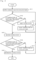
- FIG. 2 is a flowchart showing an operation flow for treatment of the exhaust gas in the engine system 10 in accordance with the present invention.
- the exhaust gas from the combustion chamber 20 is supplied to the catalyst part 62 (Step S 11).
- the temperature of the exhaust gas to be introduced into the treatment cabinet 61 i.e., the temperature of the exhaust gas to be supplied to the catalyst part 62
- the temperature of the catalyst part 62 may be also lower than the normal operating temperature.
- the temperature of the exhaust gas at the point in time when the exhaust gas is introduced into the treatment cabinet 61 (hereinafter, also referred to as an "inlet exhaust gas temperature") is, for example, lower than 250 °C, and a difference between the normal operating temperature and the inlet exhaust gas temperature (i.e., a value obtained by subtracting the inlet exhaust gas temperature from the normal operating temperature) is, for example, not lower than 90 °C.
- the inlet exhaust gas temperature is not lower than an oxidation onset temperature (i.e., a temperature at the time when heat generation due to the oxidation reaction of carbon monoxide starts).
- the inlet exhaust gas temperature is, for example, 150 °C to 350 °C.
- the engine control part 7 controls the tuning state of the engine 1 to be changed into a first tuning state different from the tuning state (hereinafter, also referred to as a "reference tuning state") during a steady operation (Step S 13). Specifically, when the tuning state of the engine 1 is the reference tuning state or a tuning state other than the first tuning state, the engine control part 7 changes the tuning state of the engine 1 into the first tuning state. Further, when the tuning state of the engine 1 is the first tuning state, the first tuning state is maintained.
- the above-described first switching temperature is a temperature lower than the normal operating temperature, and for example, a temperature not lower than the oxidation onset temperature of methane (i.e., a temperature at the time when heat generation due to the oxidation reaction of methane starts).
- the first switching temperature is set as appropriate in advance in accordance with the use manner or the like of the engine system 10.
- the concentration of carbon monoxide contained in the exhaust gas discharged from the combustion chamber 20 is higher than that in the reference tuning state.
- the carbon monoxide concentration in the exhaust gas in the first tuning state is, for example, not lower than 0.05 volume %, and preferably not lower than 0.5 volume %.
- the carbon monoxide concentration in the exhaust gas in the first tuning state is, for example, not higher than 5 volume %, preferably not higher than 4 volume %, more preferably not higher than 2.5 volume %, and further preferably not higher than 1 volume %.
- the carbon monoxide concentration in the exhaust gas in the first tuning state is made not lower than 0.05 volume % and not higher than 2.5 volume %.
- the above-described steady operation refers to an operation state during the navigation scheduled in a normal operation of a ship on which the engine system 10 is mounted, and the reference tuning state is set so that the fuel economy and the environmental load of the engine 1 during the steady operation can be substantially optimal.
- the carbon monoxide concentration in the exhaust gas in the reference tuning state is, for example, not lower than 0.005 volume % and lower than 0.04 volume %.
- the methane concentration in the exhaust gas in the reference tuning state is, for example, 0.5 volume % to 1.5 volume %.
- the methane concentration in the exhaust gas in the first tuning state may be the same as that in the reference tuning state or may be different therefrom.
- the methane concentration in the exhaust gas in the first tuning state is substantially the same as that in the reference tuning state and for example, 0.5 volume % to 1.5 volume %.
- Switching of the tuning state of the engine 1 is performed, for example, when at least one of the amount of fuel to be supplied into the combustion chamber 20, the amount of air sealed in the combustion chamber 20, and the maximum pressure in the combustion chamber 20 (also referred to as the "maximum combustion pressure") is changed. Specifically, for example, by increasing the amount of fuel to be supplied into the combustion chamber 20 (hereinafter, also referred to as the “amount of fuel supply”), the amount of air inside the combustion chamber 20 is relatively reduced and the carbon monoxide concentration in the exhaust gas to be discharged from the combustion chamber 20 increases.
- the amount of fuel supply can be changed by controlling an operation of a fuel supply pump in a not-shown fuel supply part, or the like.
- the amount of air sealed in the combustion chamber 20 (hereinafter, also referred to as the "amount of sealed air”), the carbon monoxide concentration in the exhaust gas to be discharged from the combustion chamber 20 increases. Also by reducing the maximum pressure in the combustion chamber 20, the carbon monoxide concentration in the exhaust gas to be discharged from the combustion chamber 20 increases.
- the amount of sealed air and the maximum pressure in the combustion chamber 20 can be changed by controlling a closing timing of the exhaust valve 25 at the rise of the piston 3 from the bottom dead center, or the like. Specifically, for example, by delaying the above-described closing timing of the exhaust valve 25, the amount of sealed air is reduced and the maximum pressure in the combustion chamber 20 becomes lower.
- the engine control part 7 controls any element other than the above, to thereby change at least one of the amount of fuel supply, the amount of sealed air, and the maximum pressure in the combustion chamber 20.
- the tuning state of the engine 1 is switched.
- the onset temperature of oxidation of carbon monoxide by the catalyst part 62 is lower than the normal operating temperature and the onset temperature of oxidation of methane by the catalyst part 62 and not higher than the temperature of the exhaust gas to be supplied into the catalyst part 62 (i.e., the inlet exhaust gas temperature). Therefore, carbon monoxide in the exhaust gas is oxidized by the catalyst part 62. The temperature of the catalyst part 62 is raised due to the oxidation reaction heat of carbon monoxide (Step S14).
- the onset temperature of oxidation of carbon monoxide by the catalyst part 62 is changed in various manners depending on the type of the catalyst part 62 or the like, but is, for example, 200 °C under the condition that the feed flow rate of the exhaust gas into the catalyst part 62 is 0.1 m/sec to 3.0 m/sec.
- the temperature of the catalyst part 62 rises up to the oxidation onset temperature of methane
- oxidation of methane in the exhaust gas by the catalyst part 62 is substantially started.
- the temperature of the catalyst part 62 is raised up to a temperature not lower than the above-described normal operating temperature due to the oxidation reaction heat of carbon monoxide and the oxidation reaction heat of methane.
- the oxidation of carbon monoxide and methane in the exhaust gas is continuously performed by the catalyst part 62 having a temperature not lower than the normal operating temperature.
- Step S12 the engine control part 7 controls the tuning state of the engine 1, to thereby change the tuning state from the first tuning state to second tuning state (Step S 15).
- the tuning state of the engine 1 may be changed into the second tuning state not through the first tuning state (Step S 15).
- the concentration of carbon monoxide contained in the exhaust gas discharged from the combustion chamber 20 is lower than that in the first tuning state. Further, the carbon monoxide concentration in the exhaust gas in the second tuning state is higher than that in the reference tuning state.
- the carbon monoxide concentration in the exhaust gas in the second tuning state is, for example, not lower than 0.04 volume %, and preferably not lower than 0.4 volume %.
- the carbon monoxide concentration in the exhaust gas in the second tuning state is, for example, not higher than 4 volume %, preferably not higher than 2 volume %, and more preferably not higher than 0.75 volume %.
- the carbon monoxide concentration in the exhaust gas in the second tuning state is made not lower than 0.04 volume % and not higher than 2 volume %.
- the carbon monoxide concentration in the exhaust gas in the first tuning state and the second tuning state is not lower than 0.04 volume % and not higher than 2.5 volume %.
- the carbon monoxide concentration in the exhaust gas in the first tuning state and the second tuning state is not limited within the above-described range but may be changed in various manners.
- the methane concentration in the exhaust gas in the second tuning state may be the same as that in the reference tuning state or may be different therefrom.
- the methane concentration in the exhaust gas in the second tuning state is substantially the same as that in the reference tuning state and for example, 0.5 volume % to 1.5 volume %.
- the carbon monoxide concentration in the exhaust gas is reduced and the amount of oxidation reaction heat of carbon monoxide in the catalyst part 62 is also reduced.
- the catalyst part 62 whose temperature is raised oxidation of methane as well as carbon monoxide also occurs.
- the temperature of the catalyst part 62 is raised up to not lower than the first switching temperature and raised up to a predetermined second switching temperature not lower than the normal operating temperature due to the oxidation reaction heat of carbon monoxide and the oxidation reaction heat of methane (Steps S16 and S17).
- the second switching temperature is also set as appropriate in advance in accordance with the use manner or the like of the engine system 10.
- the engine control part 7 controls the tuning state of the engine 1, to thereby change the tuning state from the second tuning state to reference tuning state (Step S 18).
- the temperature of the catalyst part 62 is raised up to not lower than the normal operating temperature, also in the reference tuning state, it is possible to suitably oxidize methane in the exhaust gas discharged from the combustion chamber 20, by the catalyst part 62. As a result, it is possible to suppress emission of methane (i.e., methane slip) into the atmosphere from the engine system 10.
- the tuning state of the engine 1 may be changed into the reference state not through the first tuning state nor the second tuning state, unlike the operation flow shown in FIG. 2 .
- the exhaust gas treatment apparatus 6 includes the treatment cabinet 61 and the catalyst part 62.
- the exhaust gas of the engine 1 which uses gas containing methane as a fuel.
- the catalyst part 62 is accommodated in the treatment cabinet 61 and oxidizes unburned methane contained in the exhaust gas.
- the catalyst part 62 oxidizes carbon monoxide contained in the exhaust gas and uses the oxidation reaction heat of carbon monoxide, to thereby raise the temperature of the catalyst part 62 up to the normal operating temperature or higher.
- the tuning state of the engine 1 should be brought into the predetermined tuning state (i.e., the first tuning state and/or the second tuning state) in which the concentration of carbon monoxide contained in the exhaust gas is higher than that during the steady operation. It is thereby possible to increase the amount of oxidation reaction heat of carbon monoxide in the catalyst part 62 and more quickly raise the temperature of the catalyst part 62 up to the above-described normal operating temperature.
- the concentration of carbon monoxide contained in the exhaust gas should be not lower than 0.04 volume % and not higher than 2.5 volume %.
- the carbon monoxide concentration not lower than 0.04 volume %, it is possible to further increase the amount of oxidation reaction heat of carbon monoxide in the catalyst part 62 and still more quickly (for example, within 120 minutes from the start of supply of the exhaust gas to the catalyst part 62) raise the temperature of the catalyst part 62 up to the above-described normal operating temperature.
- the carbon monoxide concentration not higher than 2.5 volume %, it is possible to suppress deterioration of fuel economy in the above-described tuning state (i.e., in the first tuning state and/or the second tuning state) as compared with high fuel economy during the steady operation.
- the tuning state of the engine 1 is brought into the first tuning state in which the concentration of carbon monoxide contained in the exhaust gas is higher than that during the steady operation. Further, preferably, when the temperature of the catalyst part 62 is raised up to the first switching temperature, the tuning state of the engine 1 is brought into the second tuning state in which the concentration of carbon monoxide contained in the exhaust gas is higher than that during the steady operation and lower than that in the first tuning state.
- the exhaust gas treatment apparatus 6 can suitably oxidize methane contained in the exhaust gas. Therefore, the exhaust gas treatment apparatus 6 is especially suitable for the case where the temperature of the catalyst part 62 does not easily rise up to the normal operating temperature since the temperature of the exhaust gas introduced into the treatment cabinet 61 (i.e., the inlet exhaust gas temperature) is low.
- the exhaust gas treatment apparatus 6 is especially suitable for the case where a difference between the temperature of the exhaust gas introduced into the treatment cabinet 61 and the normal operating temperature is 90 °C or more.
- the exhaust gas treatment apparatus 6 should further include the introduction temperature sensor 64 for measuring the temperature (i.e., the inlet exhaust gas temperature) of the exhaust gas introduced into the treatment cabinet 61. It is thereby possible to easily detect a state where the inlet exhaust gas temperature is low and the above-described switching or the like of the tuning state is needed.
- the introduction temperature sensor 64 for measuring the temperature (i.e., the inlet exhaust gas temperature) of the exhaust gas introduced into the treatment cabinet 61. It is thereby possible to easily detect a state where the inlet exhaust gas temperature is low and the above-described switching or the like of the tuning state is needed.
- the treatment cabinet 61 should be disposed on the upstream side relative to the turbine 51 rotated by the exhaust gas in the flow direction of the exhaust gas. It is thereby possible to introduce the exhaust gas having a higher temperature to the treatment cabinet 61, as compared with after passing through the turbine 51. As a result, since the temperature of the catalyst part 62 can be raised up to the normal operating temperature more quickly, it is possible to perform oxidation of methane in the catalyst part 62 with high efficiency.
- the treatment cabinet 61 should be disposed on the downstream side relative to the turbine 51 rotated by the exhaust gas in the flow direction of the exhaust gas. It is thereby possible to introduce the exhaust gas having a lower pressure to the treatment cabinet 61, as compared with before passing through the turbine 51. As a result, it is possible to simplify the configuration of the treatment cabinet 61. Further, since it is not necessary to change the main structure of the engine 1 in the installation of the exhaust gas treatment apparatus 6, it is possible to easily retrofit the already-existing ship with the exhaust gas treatment apparatus 6.
- the exhaust gas treatment apparatus 6 can suitably oxidize methane even when the temperature of the exhaust gas supplied to the catalyst part 62 is low, it is possible to suitably oxidize methane in the exhaust gas whose temperature is reduced due to passing through the turbine 51.
- the treatment cabinet 61 is disposed between the flue 81 and the turbine 51 and the exhaust gas used for the rotation of the turbine 51 is introduced into the treatment cabinet 61.
- the engine system 10 shown in FIGs. 1 and 3 includes the engine 1 which uses gas containing methane as a fuel and the above-described exhaust gas treatment apparatus 6 which treats the exhaust gas of the engine 1. It is thereby possible to suppress the methane slip from the engine system 10 even when the temperature of the exhaust gas is low. Therefore, the engine system 10 is especially suitable for the case where a two-stroke engine whose exhaust gas temperature is relatively low is used as the engine 1. Further, the engine system 10 is especially suitable for the case where a low-pressure two-stroke engine having a tendency to increase the methane slip, as compared with a high-pressure two-stroke engine, is used as the engine 1.
- the above-described exhaust gas treatment method is a method for oxidizing unburned methane in the exhaust gas of the engine 1 which uses gas containing methane as a fuel.
- the exhaust gas treatment method includes a step of supplying the catalyst part 62 with exhaust gas having a temperature lower than the predetermined normal operating temperature (Step S 11), a step of oxidizing carbon monoxide contained in the exhaust gas in the catalyst part 62 and using oxidation reaction heat of carbon monoxide, to thereby raise the temperature of the catalyst part 62 up to the normal operating temperature or higher (Step S 14), and a step of oxidizing methane in the exhaust gas by the catalyst part 62 having a temperature not lower than the normal operating temperature after Step S14 (Step S15).
- the temperature of the catalyst part 62 can be quickly raised up to the normal operating temperature even when the temperature of the exhaust gas supplied to the catalyst part 62 is lower than the normal operating temperature, it is thereby possible to suitably oxidize methane contained in the exhaust gas.
- the difference between the temperature of the exhaust gas introduced into the treatment cabinet 61 and the normal operating temperature may be smaller than 90 °C.
- the exhaust gas transferred from the combustion chamber 20 to the treatment cabinet 61 and/or the catalyst part 62 may be heated by a boiler steam, a heater, or the like. The heating is continued, for example, until the temperature of the catalyst part 62 rises up to the oxidation onset temperature of carbon monoxide or higher.
- the catalyst temperature sensor 63 may be omitted. Further, in the exhaust gas treatment apparatus 6, the introduction temperature sensor 64 may be omitted.
- the control of the tuning state of the engine 1 by the engine control part 7 is not limited to the above-described exemplary case but may be changed in various manners. For example, after switching the tuning state of the engine 1 from the first tuning state to the second tuning state, when the temperature of the catalyst part 62 decreases to be lower than the above-described first switching temperature for some reason, the tuning state of the engine 1 may be switched from the second tuning state to the first tuning state. Alternatively, the tuning state of the engine 1 may be switched from the second tuning state to a third tuning state where the concentration of carbon monoxide in the exhaust gas is between those in the first tuning state and the second tuning state. Further, in the control of the tuning state of the engine 1, it is not always necessary to perform the switching from the first tuning state to the second tuning state.
- the tuning state of the engine 1 is maintained to be the first tuning state and when the temperature of the catalyst part 62 reaches the second switching temperature, the tuning state is switched directly from the first tuning state to the reference tuning state.
- the concentration of carbon monoxide in the exhaust gas in the first tuning state should be not lower than 0.04 volume % and not higher than 2.5 volume %.
- the switching of the tuning state of the engine 1 does not necessarily need to be performed automatically by the engine control part 7 but may be performed manually by the operator.
- the catalyst part 62 includes one oxidation catalyst used for the oxidation of carbon monoxide and methane in the above-described exemplary case, as described above, the configuration and shape of the catalyst part 62 may be changed in various manners.
- the catalyst part 62 may include a first oxidation catalyst used for the oxidation of carbon monoxide and a second oxidation catalyst used for the oxidation of methane.
- the first oxidation catalyst and the second oxidation catalyst are different types of oxidation catalysts.
- the first oxidation catalyst is disposed on an upstream side of the flow of the exhaust gas inside the treatment cabinet 61 and the second oxidation catalyst is disposed on a downstream side relative to the first oxidation catalyst.
- the exhaust gas passing through the first oxidation catalyst is supplied.
- the catalyst part 62 carbon monoxide in the exhaust gas is oxidized when the exhaust gas flowing in the treatment cabinet 61 passes through the first oxidation catalyst, and the exhaust gas whose temperature is raised due to the oxidation reaction heat of carbon monoxide is supplied to the second oxidation catalyst.
- both the oxidation of carbon monoxide and that of methane may be performed.
- the engine 1 may use LNG which is prepared as a fuel for the engine 1, instead of BOG, as a fuel.
- the engine 1 may be a dual fuel engine which can switch between fuel gas containing methane and a heavy oil fuel, to be used.
- the engine 1 may be a four-stroke engine. Further, the engine 1 may be a high-pressure engine using a combustion method such as a diesel cycle or diffusion combustion.
- the engine system 10 may be used as a main engine of a ship other than the LNG tanker or may be used for any use other than the main engine of a ship.
Landscapes
- Engineering & Computer Science (AREA)
- Chemical & Material Sciences (AREA)
- Combustion & Propulsion (AREA)
- Mechanical Engineering (AREA)
- General Engineering & Computer Science (AREA)
- Chemical Kinetics & Catalysis (AREA)
- Health & Medical Sciences (AREA)
- Toxicology (AREA)
- General Chemical & Material Sciences (AREA)
- Oil, Petroleum & Natural Gas (AREA)
- Materials Engineering (AREA)
- Exhaust Gas After Treatment (AREA)
- Combined Controls Of Internal Combustion Engines (AREA)
- Exhaust Gas Treatment By Means Of Catalyst (AREA)
Abstract
Description
- The present invention relates to a technique for treating exhaust gas.
- The present application claims the benefit of priority to
Japanese Patent Application No. 2021-081912 filed on May 13, 2021 - Conventionally, in an LNG tanker which carries liquefied natural gas (LNG), boil off gas (BOG) which is inevitably generated from the LNG that is a cargo is used as fuel gas. Further, in recent years, the number of ships which use LNG as fuel gas has been increasing, even other than the LNG tanker.
- Thus, in the ship using LNG as fuel gas, in a case where a combustion temperature of the fuel gas in an engine is low, or the like case, there is a possibility that part of methane (CH4) in the fuel gas may remain unburned in exhaust gas and may be emitted into the atmosphere together with the exhaust gas. Since the global warming effect of methane is relatively high, it is required to prevent emission of methane into the atmosphere by treating the methane in the exhaust gas with a catalyst or the like. In an exhaust gas purification apparatus disclosed in
Japanese Patent Application Laid Open Gazette No. 2018-135808 - In
Document 1, the temperature of the catalyst, in which methane can be oxidized, is not lower than 350 °C and lower than 500 °C. Therefore, when the temperature of the exhaust gas introduced into the exhaust gas purification apparatus is lower than 350°C, it is difficult to suitably oxidize methane in the exhaust gas. - The present invention is intended for an exhaust gas treatment apparatus, and it is an object of the present invention to suitably oxidize methane in exhaust gas even when an exhaust gas temperature is low.
- The exhaust gas treatment apparatus according to one preferred embodiment of the present invention includes a treatment cabinet into which exhaust gas of an engine which uses gas containing methane as a fuel is introduced and a catalyst part accommodated in the treatment cabinet, for oxidizing unburned methane contained in the exhaust gas. When a temperature of the catalyst part is lower than a predetermined normal operating temperature, the catalyst part oxidizes carbon monoxide contained in the exhaust gas and uses oxidation reaction heat of carbon monoxide, to thereby raise the temperature of the catalyst part up to the normal operating temperature or higher.
- According to the present invention, it is possible to suitably oxidize methane in the exhaust gas even when an exhaust gas temperature is low.
- Preferably, when the temperature of the catalyst part is lower than the normal operating temperature, a tuning state of the engine is made to be a predetermined tuning state in which a concentration of carbon monoxide contained in the exhaust gas is higher than that during a steady operation.
- Preferably, when the tuning state of the engine is the predetermined tuning state, the concentration of carbon monoxide contained in the exhaust gas is not lower than 0.04 volume % and not higher than 2.5 volume %.
- Preferably, when the temperature of the catalyst part is lower than a first switching temperature which is lower than the normal operating temperature, the tuning state of the engine is made to be a first tuning state in which the concentration of carbon monoxide contained in the exhaust gas is higher than that during the steady operation. When the temperature of the catalyst part is raised up to the first switching temperature, the tuning state of the engine is made to be a second tuning state in which the concentration of carbon monoxide contained in the exhaust gas is higher than that during the steady operation and is lower than that in the first tuning state.
- Preferably, the exhaust gas treatment apparatus further includes an introduction temperature sensor for measuring a temperature of the exhaust gas introduced into the treatment cabinet.
- Preferably, the treatment cabinet is disposed on an upstream side relative to a turbine rotated by the exhaust gas in a flow direction of the exhaust gas.
- Preferably, the treatment cabinet is disposed on a downstream side relative to a turbine rotated by the exhaust gas in a flow direction of the exhaust gas.
- The present invention is also intended for an engine system. The engine system according to one preferred embodiment of the present invention includes an engine using gas containing methane as a fuel and the above-described exhaust gas treatment apparatus for treating the exhaust gas of the engine.
- Preferably, the engine is a two-stroke engine.
- The present invention is still also intended for an exhaust gas treatment method for oxidizing unburned methane in exhaust gas of an engine which uses gas containing methane as a fuel. The exhaust gas treatment method according to one preferred embodiment of the present invention includes a) supplying a catalyst part with exhaust gas having a temperature lower than a predetermined normal operating temperature, b) oxidizing carbon monoxide contained in the exhaust gas in the catalyst part and using oxidation reaction heat of carbon monoxide, to thereby raise a temperature of the catalyst part up to the normal operating temperature or higher, and c) oxidizing methane in the exhaust gas by the catalyst part having a temperature not lower than the normal operating temperature after the operation b).
- These and other objects, features, aspects and advantages of the present invention will become more apparent from the following detailed description of the present invention when taken in conjunction with the accompanying drawings.
-
-
FIG. 1 is a view showing a configuration of an engine system in accordance with one preferred embodiment; -
FIG. 2 is a flowchart showing an operation flow for treatment of exhaust gas; and -
FIG. 3 is a view showing a configuration of another engine system. -
FIG. 1 is a view showing a configuration of anengine system 10 in accordance with one preferred embodiment of the present invention. Theengine system 10 is mounted on, for example, an LNG tanker which carries liquefied natural gas (LNG). Theengine system 10 is used as, for example, a main engine of the LNG tanker. - The
engine system 10 includes anengine 1 and an exhaustgas treatment apparatus 6. Theengine 1 is a gas engine using gas containing methane (CH4) as a fuel. Theengine 1 is, for example, a two-stroke engine. Theengine 1 is a reciprocating internal combustion engine using a combustion method such as an Otto cycle, a premixed combustion, a diesel cycle, a Sabathe cycle, or the like. Theengine 1 is, for example, a low-pressure engine. Theengine 1 may use boil off gas (BOG) of liquefied natural gas (LNG) as a fuel. BOG is, for example, gas generated when LNG which is a cargo is vaporized in the LNG tanker, and contains methane. - The
engine 1 includes acylinder 2, apiston 3, ascavenging passage 41, anexhaust passage 42, anair cooler 43, a supercharger 5, anengine control part 7, and aflue 81. Thecylinder 2 is a substantially covered cylindrical member with a central axis extending in an up-and-down direction ofFIG. 1 , as its center. Thepiston 3 is a substantially columnar member with the central axis as its center, and an upper portion thereof is disposed inside thecylinder 2. Thepiston 3 is movable in the up-and-down direction. Further, the up-and-down direction ofFIG. 1 does not necessarily need to be parallel to the direction of gravity. - The
cylinder 2 includes acylinder liner 21, acylinder cover 22, and anexhaust valve 25. Thecylinder liner 21 is a substantially cylindrical member with the above-described central axis as its center. Thecylinder cover 22 is a substantially covered cylindrical member attached to an upper portion of thecylinder liner 21. In a top cover of thecylinder cover 22, formed is anexhaust port 24. Theexhaust port 24 is connected to theexhaust passage 42. Theexhaust port 24 gets opened and closed by theexhaust valve 25. As indicated by a solid line inFIG. 1 , when theexhaust valve 25 gets separated downward from theexhaust port 24, theexhaust port 24 gets opened. Further, as indicated by a two-dot chain line inFIG. 1 , when theexhaust valve 25 comes into contact with thecylinder cover 22 and overlaps theexhaust port 24, theexhaust port 24 gets closed. In the vicinity of a lower end portion of thecylinder liner 21, provided is ascavenging port 23. Thescavenging port 23 is a set of many through holes formed on a side surface of thecylinder liner 21, being circumferentially arranged. Thescavenging port 23 is connected to thescavenging passage 41. - The
piston 3 includes apiston crown 31 and apiston rod 32. Thepiston crown 31 is a substantially disk-like thick portion with the above-described central axis as its center. Thepiston crown 31 is disposed inside thecylinder liner 21. Thepiston rod 32 is a substantially columnar portion extending downward from a lower surface of thepiston crown 31. A lower end portion of thepiston rod 32 is connected to a not-shown crank mechanism. By the crank mechanism, thepiston 3 is reciprocated in the up-and-down direction. InFIG. 1 , thepiston 3 positioned at a bottom dead center of the reciprocation is represented by a solid line and thepiston 3 positioned at a top dead center thereof is represented by a two-dot chain line. - In the
engine 1, a space surrounded by thecylinder liner 21, thecylinder cover 22, theexhaust valve 25, and an upper surface of the piston crown 31 (i.e., an upper surface of the piston 3) is acombustion chamber 20 in which a fuel and air are burned. - To the
combustion chamber 20, scavenging gas is supplied from the scavengingpassage 41 through the above-described scavengingport 23. The scavengingpassage 41 includes a scavengingchamber 411 and a scavengingreceiver 412. The scavengingchamber 411 is a space (i.e., a scavenging pipe) provided around the scavengingport 23 of thecylinder liner 21. The scavengingport 23 communicates with the scavengingreceiver 412 through the scavengingchamber 411. The scavengingreceiver 412 is a substantially cylindrical large-scale container for supplying the scavenging gas to the scavengingchamber 411. - Gas (i.e., combustion gas) generated by burning the fuel and the air in the
combustion chamber 20 is discharged into theexhaust passage 42 through theexhaust port 24. Theexhaust passage 42 is a conduit line in which the gas (hereinafter, referred to as "exhaust gas") discharged from thecombustion chamber 20 flows. Theexhaust passage 42 includes anexhaust pipe 421 and anexhaust receiver 422. Theexhaust pipe 421 is a pipe connecting theexhaust port 24 and theexhaust receiver 422 to each other. Theexhaust receiver 422 is a substantially cylindrical large-scale container for receiving the exhaust gas from thecombustion chamber 20. - Though not shown, in the
engine 1, a plurality of pairs ofcylinders 2 andpistons 3 are provided and a plurality ofcombustion chambers 20 are connected to one scavengingreceiver 412 and oneexhaust receiver 422. In other words, the scavengingreceiver 412 is a scavenging manifold for distributing and supplying the scavenging gas to the plurality ofcombustion chambers 20. Further, theexhaust receiver 422 is an exhaust manifold (also referred to as an exhaust collector pipe) for collecting the exhaust gases discharged from the plurality ofcombustion chambers 20. - The exhaust gas collected to the
exhaust receiver 422 is treated by the exhaustgas treatment apparatus 6. In the exhaustgas treatment apparatus 6, unburned (i.e., unreacted) methane contained in the exhaust gas from thecombustion chambers 20 is oxidized, to thereby generate carbon dioxide (CO2) and water (H2O). A concentration (hereinafter, also referred to as a "slip methane concentration") of unburned methane contained in the exhaust gas discharged from theengine system 10 into the atmosphere is thereby made not higher than a default value. The exhaustgas treatment apparatus 6 includes atreatment cabinet 61, acatalyst part 62, acatalyst temperature sensor 63, and anintroduction temperature sensor 64. - In the exhaust
gas treatment apparatus 6, the exhaust gas from thecombustion chamber 20 is introduced into an internal space of thetreatment cabinet 61. Thetreatment cabinet 61 is, for example, a substantially cylindrical reaction container. In the internal space of thetreatment cabinet 61, thecatalyst part 62 is accommodated (i.e., loaded). Thecatalyst part 62 is, for example, an oxidation catalyst having a honeycomb structure. Specifically, thecatalyst part 62 has a structure in which the oxidation catalyst such as a catalytic metal or the like is supported by a carrier having a honeycomb structure. The catalytic metal includes, for example, a precious metal such as palladium (Pd), platinum (Pt), or the like. In the exhaustgas treatment apparatus 6, when the exhaust gas introduced into thetreatment cabinet 61 passes through thecatalyst part 62, the unburned methane contained in the exhaust gas is oxidized by thecatalyst part 62. Further, thecatalyst part 62 also oxidizes carbon monoxide (CO) contained in the exhaust gas. Furthermore, respective structures and shapes of thetreatment cabinet 61 and thecatalyst part 62 may be changed in various manners. For example, the carrier of thecatalyst part 62 may have any other shape such as a cylindrical shape, a flat plate-like shape, or the like. - The
catalyst temperature sensor 63 measures a temperature of thecatalyst part 62 and outputs the measured temperature to theengine control part 7. Thecatalyst temperature sensor 63 may measure a temperature of the internal space of thetreatment cabinet 61 and output a measurement result to theengine control part 7 as the temperature of thecatalyst part 62. Theintroduction temperature sensor 64 measures a temperature of the exhaust gas at the point in time when the exhaust gas is introduced into thetreatment cabinet 61 and outputs the measured temperature to theengine control part 7. Theintroduction temperature sensor 64 is provided just before an introduction port of thetreatment cabinet 61 in the pipe connecting theexhaust receiver 422 and thetreatment cabinet 61 to each other. As thecatalyst temperature sensor 63 and theintroduction temperature sensor 64, for example, a thermocouple can be used. - In the exhaust
gas treatment apparatus 6, a predetermined normal operating temperature is set and when the temperature of thecatalyst part 62 is not lower than the normal operating temperature, oxidation of the methane in the exhaust gas is sufficiently performed and the slip methane concentration becomes not higher than the above-described default value. The normal operating temperature may be, for example, the temperature of thecatalyst part 62 at the time when the slip methane concentration becomes equal to the default value or may be a temperature obtained by adding a predetermined margin (e.g., 10 °C to 50 °C) to the temperature. The normal operating temperature is, for example, set by a manufacturer who manufactures the exhaustgas treatment apparatus 6 or theengine system 10, or the like. Though the normal operating temperature is changed in various manners depending on the type of thecatalyst part 62, or the like, the normal operating temperature is, for example, 400 °C under the condition that the feed flow rate of the exhaust gas into thecatalyst part 62 is 0.1 m/sec to 3.0 m/sec. Further, when the temperature of thecatalyst part 62 is lower than the normal operating temperature, there is a possibility that the slip methane concentration may exceed the above-described default value. - The supercharger 5 is a turbocharger which includes a
turbine 51 and acompressor 52. The supercharger 5 pressurizes intake gas by using the exhaust gas, to thereby generate scavenging gas. Specifically, theturbine 51 is rotated by the exhaust gas from thecombustion chamber 20, and thecompressor 52 uses a rotating force generated in the turbine 51 (in other words, uses the rotation of theturbine 51 as a power) to pressurize and compress the intake gas (air) taken in from the outside of theengine 1 through anintake path 82. The pressurized air (i.e., the above-described scavenging gas) is cooled by theair cooler 43, and then is supplied to the scavengingreceiver 412 and further supplied from the scavengingreceiver 412 to thecombustion chamber 20. The exhaust gas used for the rotation of theturbine 51 is guided to theflue 81 and discharged from theflue 81 to the outside of theengine 1. In the exemplary case shown inFIG. 1 , theturbine 51 is disposed between theflue 81 and thetreatment cabinet 61 of the exhaustgas treatment apparatus 6. In other words, thetreatment cabinet 61 is disposed on an upstream side relative to theturbine 51 rotated by the exhaust gas in a flow direction of the exhaust gas discharged from thecombustion chamber 20. The exhaust gas after being treated by thecatalyst part 62 in thetreatment cabinet 61 is introduced into theturbine 51. - The
engine control part 7 controls a tuning state of theengine 1 on the basis of an output (i.e., the temperature of the catalyst part 62) from thecatalyst temperature sensor 63 of the exhaustgas treatment apparatus 6. Theengine control part 7 is, for example, a programmable logic controller (PLC). The PLC includes a processor, a memory, an input/output part, and a bus. The bus is a signal circuit for connecting the processor, the memory, and the input/output part to one another. The memory stores therein a program and various information. The processor performs various processings (for example, numerical calculation or the like) while using the memory and the like in accordance with the program and the like stored in the memory. The input/output part receives a signal input from any other apparatus (for example, the exhaust gas treatment apparatus 6) and an input from an operator, and outputs a signal to any other apparatus. The PLC performs a processing on the basis of a predetermined program, to thereby implement functions of theengine control part 7. Theengine control part 7 may be a general-type computer system including a keyboard, a display, and the like, or may be a circuit board or the like. - In the
engine system 10, at the startup of theengine 1, during a low-power operation, or the like, the temperature of the exhaust gas transferred from thecombustion chamber 20 to the exhaustgas treatment apparatus 6 is sometimes relatively low. The temperature outputted from theintroduction temperature sensor 64 to the engine control part 7 (i.e., the temperature of the exhaust gas at the point in time when the exhaust gas is introduced into the treatment cabinet 61) is, for example, sometimes lower than the above-described normal operating temperature. In such a case where the temperature of the exhaust gas to be introduced into thetreatment cabinet 61 is relatively low, since oxidation of the methane by thecatalyst part 62 hardly proceeds and oxidation reaction heat generated by the oxidation is little in the conventional exhaust gas treatment apparatus, there is a possibility that the temperature of thecatalyst part 62 cannot reach the above-described normal operating temperature. -
FIG. 2 is a flowchart showing an operation flow for treatment of the exhaust gas in theengine system 10 in accordance with the present invention. In theengine system 10, in a state where the temperature of thecatalyst part 62 is measured by thecatalyst temperature sensor 63, the exhaust gas from thecombustion chamber 20 is supplied to the catalyst part 62 (Step S 11). As described above, when the temperature of the exhaust gas to be introduced into the treatment cabinet 61 (i.e., the temperature of the exhaust gas to be supplied to the catalyst part 62) is lower than the normal operating temperature, there is a possibility that the temperature of thecatalyst part 62 may be also lower than the normal operating temperature. At the startup of theengine 1, during the low-power operation, or the like, the temperature of the exhaust gas at the point in time when the exhaust gas is introduced into the treatment cabinet 61 (hereinafter, also referred to as an "inlet exhaust gas temperature") is, for example, lower than 250 °C, and a difference between the normal operating temperature and the inlet exhaust gas temperature (i.e., a value obtained by subtracting the inlet exhaust gas temperature from the normal operating temperature) is, for example, not lower than 90 °C. The inlet exhaust gas temperature is not lower than an oxidation onset temperature (i.e., a temperature at the time when heat generation due to the oxidation reaction of carbon monoxide starts). The inlet exhaust gas temperature is, for example, 150 °C to 350 °C. - When the temperature of the
catalyst part 62, which is transmitted from thecatalyst temperature sensor 63 to theengine control part 7, is lower than a predetermined first switching temperature (Step S12), theengine control part 7 controls the tuning state of theengine 1 to be changed into a first tuning state different from the tuning state (hereinafter, also referred to as a "reference tuning state") during a steady operation (Step S 13). Specifically, when the tuning state of theengine 1 is the reference tuning state or a tuning state other than the first tuning state, theengine control part 7 changes the tuning state of theengine 1 into the first tuning state. Further, when the tuning state of theengine 1 is the first tuning state, the first tuning state is maintained. The above-described first switching temperature is a temperature lower than the normal operating temperature, and for example, a temperature not lower than the oxidation onset temperature of methane (i.e., a temperature at the time when heat generation due to the oxidation reaction of methane starts). The first switching temperature is set as appropriate in advance in accordance with the use manner or the like of theengine system 10. - In the first tuning state, the concentration of carbon monoxide contained in the exhaust gas discharged from the
combustion chamber 20 is higher than that in the reference tuning state. The carbon monoxide concentration in the exhaust gas in the first tuning state is, for example, not lower than 0.05 volume %, and preferably not lower than 0.5 volume %. The carbon monoxide concentration in the exhaust gas in the first tuning state is, for example, not higher than 5 volume %, preferably not higher than 4 volume %, more preferably not higher than 2.5 volume %, and further preferably not higher than 1 volume %. In the present preferred embodiment, the carbon monoxide concentration in the exhaust gas in the first tuning state is made not lower than 0.05 volume % and not higher than 2.5 volume %. Further, the above-described steady operation refers to an operation state during the navigation scheduled in a normal operation of a ship on which theengine system 10 is mounted, and the reference tuning state is set so that the fuel economy and the environmental load of theengine 1 during the steady operation can be substantially optimal. The carbon monoxide concentration in the exhaust gas in the reference tuning state is, for example, not lower than 0.005 volume % and lower than 0.04 volume %. - Further, the methane concentration in the exhaust gas in the reference tuning state is, for example, 0.5 volume % to 1.5 volume %. The methane concentration in the exhaust gas in the first tuning state may be the same as that in the reference tuning state or may be different therefrom. In the present preferred embodiment, the methane concentration in the exhaust gas in the first tuning state is substantially the same as that in the reference tuning state and for example, 0.5 volume % to 1.5 volume %. By making the methane concentration in the exhaust gas not lower than 0.5 volume %, it is possible to perform the oxidation of methane in the
catalyst part 62 with high efficiency. Further, by making the methane concentration in the exhaust gas not higher than 1.5 volume %, it is possible to prevent excessive temperature rise of thecatalyst part 62 due to the oxidation reaction heat of methane in thecatalyst part 62. - Switching of the tuning state of the
engine 1 is performed, for example, when at least one of the amount of fuel to be supplied into thecombustion chamber 20, the amount of air sealed in thecombustion chamber 20, and the maximum pressure in the combustion chamber 20 (also referred to as the "maximum combustion pressure") is changed. Specifically, for example, by increasing the amount of fuel to be supplied into the combustion chamber 20 (hereinafter, also referred to as the "amount of fuel supply"), the amount of air inside thecombustion chamber 20 is relatively reduced and the carbon monoxide concentration in the exhaust gas to be discharged from thecombustion chamber 20 increases. The amount of fuel supply can be changed by controlling an operation of a fuel supply pump in a not-shown fuel supply part, or the like. - Further, for example, by reducing the amount of air sealed in the combustion chamber 20 (hereinafter, also referred to as the "amount of sealed air"), the carbon monoxide concentration in the exhaust gas to be discharged from the
combustion chamber 20 increases. Also by reducing the maximum pressure in thecombustion chamber 20, the carbon monoxide concentration in the exhaust gas to be discharged from thecombustion chamber 20 increases. The amount of sealed air and the maximum pressure in thecombustion chamber 20 can be changed by controlling a closing timing of theexhaust valve 25 at the rise of thepiston 3 from the bottom dead center, or the like. Specifically, for example, by delaying the above-described closing timing of theexhaust valve 25, the amount of sealed air is reduced and the maximum pressure in thecombustion chamber 20 becomes lower. - Further, in the switching of the tuning state of the
engine 1, there may be a case where theengine control part 7 controls any element other than the above, to thereby change at least one of the amount of fuel supply, the amount of sealed air, and the maximum pressure in thecombustion chamber 20. Alternatively, there may be a case where by controlling any element other than the amount of fuel supply, the amount of sealed air, and the maximum pressure in thecombustion chamber 20, the tuning state of theengine 1 is switched. - The onset temperature of oxidation of carbon monoxide by the
catalyst part 62 is lower than the normal operating temperature and the onset temperature of oxidation of methane by thecatalyst part 62 and not higher than the temperature of the exhaust gas to be supplied into the catalyst part 62 (i.e., the inlet exhaust gas temperature). Therefore, carbon monoxide in the exhaust gas is oxidized by thecatalyst part 62. The temperature of thecatalyst part 62 is raised due to the oxidation reaction heat of carbon monoxide (Step S14). Further, the onset temperature of oxidation of carbon monoxide by thecatalyst part 62 is changed in various manners depending on the type of thecatalyst part 62 or the like, but is, for example, 200 °C under the condition that the feed flow rate of the exhaust gas into thecatalyst part 62 is 0.1 m/sec to 3.0 m/sec. - In the
engine system 10, as described above, since the tuning state of theengine 1 is changed to the first tuning state and the carbon monoxide concentration in the exhaust gas is increased, the amount of oxidation reaction heat of carbon monoxide oxidized by thecatalyst part 62 is large. Therefore, the temperature of thecatalyst part 62 is quickly raised and reaches the above-described oxidation onset temperature of methane, - After the temperature of the
catalyst part 62 rises up to the oxidation onset temperature of methane, oxidation of methane in the exhaust gas by thecatalyst part 62 is substantially started. The temperature of thecatalyst part 62 is raised up to a temperature not lower than the above-described normal operating temperature due to the oxidation reaction heat of carbon monoxide and the oxidation reaction heat of methane. Then, the oxidation of carbon monoxide and methane in the exhaust gas is continuously performed by thecatalyst part 62 having a temperature not lower than the normal operating temperature. - In the exhaust
gas treatment apparatus 6, measurement of the temperature of thecatalyst part 62 is continuously performed by thecatalyst temperature sensor 63, and when the temperature of thecatalyst part 62, which is transmitted from thecatalyst temperature sensor 63 to theengine control part 7, reaches the first switching temperature (Step S12), theengine control part 7 controls the tuning state of theengine 1, to thereby change the tuning state from the first tuning state to second tuning state (Step S 15). Further, even during the low-power operation or the like, in a case where the temperature of thecatalyst part 62, which is transmitted from thecatalyst temperature sensor 63 to theengine control part 7, is not lower than the first switching temperature and lower than the normal operating temperature from the beginning (Step S12), or the like case, the tuning state of theengine 1 may be changed into the second tuning state not through the first tuning state (Step S 15). - In the second tuning state, the concentration of carbon monoxide contained in the exhaust gas discharged from the
combustion chamber 20 is lower than that in the first tuning state. Further, the carbon monoxide concentration in the exhaust gas in the second tuning state is higher than that in the reference tuning state. The carbon monoxide concentration in the exhaust gas in the second tuning state is, for example, not lower than 0.04 volume %, and preferably not lower than 0.4 volume %. The carbon monoxide concentration in the exhaust gas in the second tuning state is, for example, not higher than 4 volume %, preferably not higher than 2 volume %, and more preferably not higher than 0.75 volume %. In the present preferred embodiment, the carbon monoxide concentration in the exhaust gas in the second tuning state is made not lower than 0.04 volume % and not higher than 2 volume %. In other words, in the present preferred embodiment, the carbon monoxide concentration in the exhaust gas in the first tuning state and the second tuning state is not lower than 0.04 volume % and not higher than 2.5 volume %. Further, the carbon monoxide concentration in the exhaust gas in the first tuning state and the second tuning state is not limited within the above-described range but may be changed in various manners. The methane concentration in the exhaust gas in the second tuning state may be the same as that in the reference tuning state or may be different therefrom. In the present preferred embodiment, the methane concentration in the exhaust gas in the second tuning state is substantially the same as that in the reference tuning state and for example, 0.5 volume % to 1.5 volume %. - As described above, in the second tuning state as compared with those in the first tuning state, the carbon monoxide concentration in the exhaust gas is reduced and the amount of oxidation reaction heat of carbon monoxide in the
catalyst part 62 is also reduced. On the other hand, in thecatalyst part 62 whose temperature is raised, oxidation of methane as well as carbon monoxide also occurs. Since the amount of oxidation reaction heat (i.e., combustion heat) of methane per unit amount of substance is larger than that of carbon monoxide per unit amount of substance, the temperature of thecatalyst part 62 is raised up to not lower than the first switching temperature and raised up to a predetermined second switching temperature not lower than the normal operating temperature due to the oxidation reaction heat of carbon monoxide and the oxidation reaction heat of methane (Steps S16 and S17). Like the first switching temperature, the second switching temperature is also set as appropriate in advance in accordance with the use manner or the like of theengine system 10. - Then, after the temperature of the
catalyst part 62 reaches the second switching temperature (Step S16), theengine control part 7 controls the tuning state of theengine 1, to thereby change the tuning state from the second tuning state to reference tuning state (Step S 18). In the exhaustgas treatment apparatus 6, since the temperature of thecatalyst part 62 is raised up to not lower than the normal operating temperature, also in the reference tuning state, it is possible to suitably oxidize methane in the exhaust gas discharged from thecombustion chamber 20, by thecatalyst part 62. As a result, it is possible to suppress emission of methane (i.e., methane slip) into the atmosphere from theengine system 10. Further, when the temperature of thecatalyst part 62, which is transmitted from thecatalyst temperature sensor 63 to theengine control part 7, is not lower than the second switching temperature from the beginning, the tuning state of theengine 1 may be changed into the reference state not through the first tuning state nor the second tuning state, unlike the operation flow shown inFIG. 2 . - As described above, the exhaust
gas treatment apparatus 6 includes thetreatment cabinet 61 and thecatalyst part 62. To thetreatment cabinet 61, introduced is the exhaust gas of theengine 1 which uses gas containing methane as a fuel. Thecatalyst part 62 is accommodated in thetreatment cabinet 61 and oxidizes unburned methane contained in the exhaust gas. When the temperature of thecatalyst part 62 is lower than the predetermined normal operating temperature, thecatalyst part 62 oxidizes carbon monoxide contained in the exhaust gas and uses the oxidation reaction heat of carbon monoxide, to thereby raise the temperature of thecatalyst part 62 up to the normal operating temperature or higher. Even when the temperature of exhaust gas supplied to thecatalyst part 62 is lower than the normal operating temperature, it is thereby possible to quickly raise the temperature of thecatalyst part 62 up to the normal operating temperature or higher. Therefore, it is possible to suitably oxidize methane in the exhaust gas and suitably suppress the methane slip. As a result, the slip methane concentration can be made not higher than the above-described default value - As described above, when the temperature of the
catalyst part 62 is lower than the normal operating temperature, it is preferable that the tuning state of theengine 1 should be brought into the predetermined tuning state (i.e., the first tuning state and/or the second tuning state) in which the concentration of carbon monoxide contained in the exhaust gas is higher than that during the steady operation. It is thereby possible to increase the amount of oxidation reaction heat of carbon monoxide in thecatalyst part 62 and more quickly raise the temperature of thecatalyst part 62 up to the above-described normal operating temperature. - As described above, when the tuning state of the
engine 1 is the above-described predetermined tuning state, it is preferable that the concentration of carbon monoxide contained in the exhaust gas should be not lower than 0.04 volume % and not higher than 2.5 volume %. By making the carbon monoxide concentration not lower than 0.04 volume %, it is possible to further increase the amount of oxidation reaction heat of carbon monoxide in thecatalyst part 62 and still more quickly (for example, within 120 minutes from the start of supply of the exhaust gas to the catalyst part 62) raise the temperature of thecatalyst part 62 up to the above-described normal operating temperature. Further, by making the carbon monoxide concentration not higher than 2.5 volume %, it is possible to suppress deterioration of fuel economy in the above-described tuning state (i.e., in the first tuning state and/or the second tuning state) as compared with high fuel economy during the steady operation. - As described above, preferably, when the temperature of the
catalyst part 62 is lower than the first switching temperature lower than the normal operating temperature, the tuning state of theengine 1 is brought into the first tuning state in which the concentration of carbon monoxide contained in the exhaust gas is higher than that during the steady operation. Further, preferably, when the temperature of thecatalyst part 62 is raised up to the first switching temperature, the tuning state of theengine 1 is brought into the second tuning state in which the concentration of carbon monoxide contained in the exhaust gas is higher than that during the steady operation and lower than that in the first tuning state. It is thereby possible to reduce the amount of oxidation reaction heat of carbon monoxide in thecatalyst part 62 and prevent excessive temperature rise of thecatalyst part 62 in a state where the temperature of thecatalyst part 62 is not lower than the first switching temperature. Furthermore, since the tuning state of theengine 1 becomes closer to the reference tuning state than the first tuning state, it is possible to further suppress the deterioration of fuel economy as compared with that during the steady operation. As a result, it is possible to suitably suppress the methane slip while suppressing the deterioration of fuel economy, from the state where the exhaust gas temperature is low, such as at the start of operation or the like, to during the steady operation. - As described above, even when the temperature of the exhaust gas supplied to the
catalyst part 62 is lower than the normal operating temperature, the exhaustgas treatment apparatus 6 can suitably oxidize methane contained in the exhaust gas. Therefore, the exhaustgas treatment apparatus 6 is especially suitable for the case where the temperature of thecatalyst part 62 does not easily rise up to the normal operating temperature since the temperature of the exhaust gas introduced into the treatment cabinet 61 (i.e., the inlet exhaust gas temperature) is low. For example, the exhaustgas treatment apparatus 6 is especially suitable for the case where a difference between the temperature of the exhaust gas introduced into thetreatment cabinet 61 and the normal operating temperature is 90 °C or more. - As described above, it is preferable that the exhaust
gas treatment apparatus 6 should further include theintroduction temperature sensor 64 for measuring the temperature (i.e., the inlet exhaust gas temperature) of the exhaust gas introduced into thetreatment cabinet 61. It is thereby possible to easily detect a state where the inlet exhaust gas temperature is low and the above-described switching or the like of the tuning state is needed. - As described above, it is preferable that the
treatment cabinet 61 should be disposed on the upstream side relative to theturbine 51 rotated by the exhaust gas in the flow direction of the exhaust gas. It is thereby possible to introduce the exhaust gas having a higher temperature to thetreatment cabinet 61, as compared with after passing through theturbine 51. As a result, since the temperature of thecatalyst part 62 can be raised up to the normal operating temperature more quickly, it is possible to perform oxidation of methane in thecatalyst part 62 with high efficiency. - Further, as shown in
FIG. 3 , it is also preferable that thetreatment cabinet 61 should be disposed on the downstream side relative to theturbine 51 rotated by the exhaust gas in the flow direction of the exhaust gas. It is thereby possible to introduce the exhaust gas having a lower pressure to thetreatment cabinet 61, as compared with before passing through theturbine 51. As a result, it is possible to simplify the configuration of thetreatment cabinet 61. Further, since it is not necessary to change the main structure of theengine 1 in the installation of the exhaustgas treatment apparatus 6, it is possible to easily retrofit the already-existing ship with the exhaustgas treatment apparatus 6. Further, as described above, since the exhaustgas treatment apparatus 6 can suitably oxidize methane even when the temperature of the exhaust gas supplied to thecatalyst part 62 is low, it is possible to suitably oxidize methane in the exhaust gas whose temperature is reduced due to passing through theturbine 51. In the exemplary case shown inFIG. 3 , thetreatment cabinet 61 is disposed between theflue 81 and theturbine 51 and the exhaust gas used for the rotation of theturbine 51 is introduced into thetreatment cabinet 61. - The
engine system 10 shown inFIGs. 1 and3 includes theengine 1 which uses gas containing methane as a fuel and the above-described exhaustgas treatment apparatus 6 which treats the exhaust gas of theengine 1. It is thereby possible to suppress the methane slip from theengine system 10 even when the temperature of the exhaust gas is low. Therefore, theengine system 10 is especially suitable for the case where a two-stroke engine whose exhaust gas temperature is relatively low is used as theengine 1. Further, theengine system 10 is especially suitable for the case where a low-pressure two-stroke engine having a tendency to increase the methane slip, as compared with a high-pressure two-stroke engine, is used as theengine 1. - The above-described exhaust gas treatment method is a method for oxidizing unburned methane in the exhaust gas of the
engine 1 which uses gas containing methane as a fuel. The exhaust gas treatment method includes a step of supplying thecatalyst part 62 with exhaust gas having a temperature lower than the predetermined normal operating temperature (Step S 11), a step of oxidizing carbon monoxide contained in the exhaust gas in thecatalyst part 62 and using oxidation reaction heat of carbon monoxide, to thereby raise the temperature of thecatalyst part 62 up to the normal operating temperature or higher (Step S 14), and a step of oxidizing methane in the exhaust gas by thecatalyst part 62 having a temperature not lower than the normal operating temperature after Step S14 (Step S15). In the same manner as above, since the temperature of thecatalyst part 62 can be quickly raised up to the normal operating temperature even when the temperature of the exhaust gas supplied to thecatalyst part 62 is lower than the normal operating temperature, it is thereby possible to suitably oxidize methane contained in the exhaust gas. - In the exhaust
gas treatment apparatus 6, theengine system 10, and the exhaust gas treatment method described above, various modifications can be made. - For example, the difference between the temperature of the exhaust gas introduced into the
treatment cabinet 61 and the normal operating temperature may be smaller than 90 °C. - Further, in a case where the temperature of the exhaust gas discharged from the
combustion chamber 20 is lower than the oxidation onset temperature of carbon monoxide, or the like case, in order to promote the oxidation of carbon monoxide by thecatalyst part 62, the exhaust gas transferred from thecombustion chamber 20 to thetreatment cabinet 61 and/or thecatalyst part 62 may be heated by a boiler steam, a heater, or the like. The heating is continued, for example, until the temperature of thecatalyst part 62 rises up to the oxidation onset temperature of carbon monoxide or higher. - In the exhaust
gas treatment apparatus 6, it is not always necessary to switch the tuning state of theengine 1 on the basis of a temperature measurement result by thecatalyst temperature sensor 63. There may be a case, for example, where a table or the like indicating a relation between operating conditions such as an elapsed time from a startup of theengine 1, an output power (the number of rotation), and the like, and the exhaust gas temperature and the temperature of thecatalyst part 62 is prepared and the exhaust gas temperature and the temperature of thecatalyst part 62 are estimated from the actual operating conditions and the table or the like. In this case, thecatalyst temperature sensor 63 may be omitted. Further, in the exhaustgas treatment apparatus 6, theintroduction temperature sensor 64 may be omitted. - The control of the tuning state of the
engine 1 by theengine control part 7 is not limited to the above-described exemplary case but may be changed in various manners. For example, after switching the tuning state of theengine 1 from the first tuning state to the second tuning state, when the temperature of thecatalyst part 62 decreases to be lower than the above-described first switching temperature for some reason, the tuning state of theengine 1 may be switched from the second tuning state to the first tuning state. Alternatively, the tuning state of theengine 1 may be switched from the second tuning state to a third tuning state where the concentration of carbon monoxide in the exhaust gas is between those in the first tuning state and the second tuning state. Further, in the control of the tuning state of theengine 1, it is not always necessary to perform the switching from the first tuning state to the second tuning state. Specifically, for example, in a case where the second tuning state is not set in theengine 1 and the temperature of thecatalyst part 62 is lower than the above-described second switching temperature, the tuning state of theengine 1 is maintained to be the first tuning state and when the temperature of thecatalyst part 62 reaches the second switching temperature, the tuning state is switched directly from the first tuning state to the reference tuning state. In this case, it is preferable that the concentration of carbon monoxide in the exhaust gas in the first tuning state should be not lower than 0.04 volume % and not higher than 2.5 volume %. Further, the switching of the tuning state of theengine 1 does not necessarily need to be performed automatically by theengine control part 7 but may be performed manually by the operator. - In order to make the carbon monoxide concentration in the exhaust gas higher than that during the steady operation, it is also not always necessary to switch the tuning state of the
engine 1 from the reference tuning state during the steady operation to the first tuning state. There may be a case, for example, where a gas separation apparatus or the like is disposed between thecombustion chamber 20 and thetreatment cabinet 61 and the gas separation apparatus or the like increases the carbon monoxide concentration in the exhaust gas introduced into thetreatment cabinet 61. Alternatively, exhaust gas recirculation (EGR) may be performed, to thereby reduce an oxygen concentration of the scavenging gas and increase the carbon monoxide concentration in the exhaust gas. - Though the
catalyst part 62 includes one oxidation catalyst used for the oxidation of carbon monoxide and methane in the above-described exemplary case, as described above, the configuration and shape of thecatalyst part 62 may be changed in various manners. For example, thecatalyst part 62 may include a first oxidation catalyst used for the oxidation of carbon monoxide and a second oxidation catalyst used for the oxidation of methane. The first oxidation catalyst and the second oxidation catalyst are different types of oxidation catalysts. In this case, the first oxidation catalyst is disposed on an upstream side of the flow of the exhaust gas inside thetreatment cabinet 61 and the second oxidation catalyst is disposed on a downstream side relative to the first oxidation catalyst. To the second oxidation catalyst, the exhaust gas passing through the first oxidation catalyst is supplied. In thecatalyst part 62, carbon monoxide in the exhaust gas is oxidized when the exhaust gas flowing in thetreatment cabinet 61 passes through the first oxidation catalyst, and the exhaust gas whose temperature is raised due to the oxidation reaction heat of carbon monoxide is supplied to the second oxidation catalyst. Also in this case, in substantially the same manner as above, it is possible to quickly raise the temperature of the second oxidation catalyst in thecatalyst part 62 up to the normal operating temperature or higher. Therefore, it is possible to suitably oxidize methane in the exhaust gas and suitably suppress the methane slip. Further, in the second oxidation catalyst, both the oxidation of carbon monoxide and that of methane may be performed. - The
engine 1 may use LNG which is prepared as a fuel for theengine 1, instead of BOG, as a fuel. Alternatively, theengine 1 may be a dual fuel engine which can switch between fuel gas containing methane and a heavy oil fuel, to be used. - The
engine 1 may be a four-stroke engine. Further, theengine 1 may be a high-pressure engine using a combustion method such as a diesel cycle or diffusion combustion. - The
engine system 10 may be used as a main engine of a ship other than the LNG tanker or may be used for any use other than the main engine of a ship. - The configurations in the above-described preferred embodiment and variations may be combined as appropriate only if those do not conflict with one another.
- While the invention has been shown and described in detail, the foregoing description is in all aspects illustrative and not restrictive. It is therefore understood that numerous modifications and variations can be devised without departing from the scope of the invention.
-
- 1
- Engine
- 6
- Exhaust gas treatment apparatus
- 10
- Engine system
- 51
- Turbine
- 61
- Treatment cabinet
- 62
- Catalyst part
- S11 to S18
- Step
Claims (10)
- An exhaust gas treatment apparatus, comprising:a treatment cabinet into which exhaust gas of an engine which uses gas containing methane as a fuel is introduced; anda catalyst part accommodated in said treatment cabinet, for oxidizing unburned methane contained in said exhaust gas,wherein when a temperature of said catalyst part is lower than a predetermined normal operating temperature, said catalyst part oxidizes carbon monoxide contained in said exhaust gas and uses oxidation reaction heat of carbon monoxide, to thereby raise the temperature of said catalyst part up to said normal operating temperature or higher.
- The exhaust gas treatment apparatus according to claim 1, wherein
when the temperature of said catalyst part is lower than said normal operating temperature, a tuning state of said engine is made to be a predetermined tuning state in which a concentration of carbon monoxide contained in said exhaust gas is higher than that during a steady operation. - The exhaust gas treatment apparatus according to claim 2, wherein
when said tuning state of said engine is said predetermined tuning state, the concentration of carbon monoxide contained in said exhaust gas is not lower than 0.04 volume % and not higher than 2.5 volume %. - The exhaust gas treatment apparatus according to claim 2 or 3, wherein
when the temperature of said catalyst part is lower than a first switching temperature which is lower than said normal operating temperature, said tuning state of said engine is made to be a first tuning state in which the concentration of carbon monoxide contained in said exhaust gas is higher than that during said steady operation, and when the temperature of said catalyst part is raised up to said first switching temperature, said tuning state of said engine is made to be a second tuning state in which the concentration of carbon monoxide contained in said exhaust gas is higher than that during said steady operation and is lower than that in said first tuning state. - The exhaust gas treatment apparatus according to any one of claims 1 to 4, further comprising:
an introduction temperature sensor for measuring a temperature of said exhaust gas introduced into said treatment cabinet. - The exhaust gas treatment apparatus according to any one of claims 1 to 5, wherein
said treatment cabinet is disposed on an upstream side relative to a turbine rotated by said exhaust gas in a flow direction of said exhaust gas. - The exhaust gas treatment apparatus according to any one of claims 1 to 5, wherein
said treatment cabinet is disposed on a downstream side relative to a turbine rotated by said exhaust gas in a flow direction of said exhaust gas. - An engine system, comprising:an engine using gas containing methane as a fuel; andsaid exhaust gas treatment apparatus according to any one of claims 1 to 7, for treating said exhaust gas of said engine.
- The engine system according to claim 8, wherein
said engine is a two-stroke engine. - An exhaust gas treatment method for oxidizing unburned methane in exhaust gas of an engine which uses gas containing methane as a fuel, comprising:a) supplying a catalyst part with exhaust gas having a temperature lower than a predetermined normal operating temperature;b) oxidizing carbon monoxide contained in said exhaust gas in said catalyst part and using oxidation reaction heat of carbon monoxide, to thereby raise a temperature of said catalyst part up to said normal operating temperature or higher; andc) oxidizing methane in said exhaust gas by said catalyst part having a temperature not lower than said normal operating temperature after said operation b).
Applications Claiming Priority (2)
| Application Number | Priority Date | Filing Date | Title |
|---|---|---|---|
| JP2021081912A JP7530862B2 (en) | 2021-05-13 | 2021-05-13 | Exhaust treatment device, engine system and exhaust treatment method |
| PCT/JP2022/013951 WO2022239506A1 (en) | 2021-05-13 | 2022-03-24 | Exhaust processing device, engine system, and exhaust processing method |
Publications (2)
| Publication Number | Publication Date |
|---|---|
| EP4339429A1 true EP4339429A1 (en) | 2024-03-20 |
| EP4339429A4 EP4339429A4 (en) | 2025-05-28 |
Family
ID=84029528
Family Applications (1)
| Application Number | Title | Priority Date | Filing Date |
|---|---|---|---|
| EP22807211.2A Pending EP4339429A4 (en) | 2021-05-13 | 2022-03-24 | EXHAUST TREATMENT DEVICE, ENGINE SYSTEM, AND EXHAUST TREATMENT METHOD |
Country Status (7)
| Country | Link |
|---|---|
| US (1) | US12123335B2 (en) |
| EP (1) | EP4339429A4 (en) |
| JP (1) | JP7530862B2 (en) |
| KR (1) | KR102870838B1 (en) |
| CN (1) | CN117255891A (en) |
| TW (1) | TWI900755B (en) |
| WO (1) | WO2022239506A1 (en) |
Families Citing this family (1)
| Publication number | Priority date | Publication date | Assignee | Title |
|---|---|---|---|---|
| CN116592383B (en) * | 2023-03-29 | 2025-11-21 | 四川川锅环保工程有限公司 | Gas flow control method for gas boiler for maintaining excess capacity of gas tank of steel mill |
Family Cites Families (18)
| Publication number | Priority date | Publication date | Assignee | Title |
|---|---|---|---|---|
| US6244044B1 (en) * | 1999-09-20 | 2001-06-12 | Southwest Research Institute | Method for reducing cold-start hydrocarbon emissions in a gasoline, natural gas, or propane fueled engine |
| CA2534031C (en) * | 2006-02-03 | 2008-06-10 | Westport Research Inc. | Method and apparatus for operating a methane-fuelled engine and treating exhaust gas with a methane oxidation catalyst |
| JP5639337B2 (en) * | 2006-03-30 | 2014-12-10 | ユミコア日本触媒株式会社 | Internal combustion engine exhaust gas purification method |
| JP4902632B2 (en) * | 2008-12-17 | 2012-03-21 | 本田技研工業株式会社 | Exhaust gas purification device for internal combustion engine |
| JP2011001829A (en) | 2009-06-16 | 2011-01-06 | Yanmar Co Ltd | Exhaust emission control device for gas engine |
| JP5939971B2 (en) | 2011-12-19 | 2016-06-29 | 大阪瓦斯株式会社 | Exhaust gas purification apparatus and exhaust gas purification method |
| US20150078975A1 (en) * | 2013-09-16 | 2015-03-19 | International Engine Intellectual Property Company, Llc | Natural gas engine aftertreatment system |
| US9038606B1 (en) * | 2013-11-07 | 2015-05-26 | EcoDual, Inc. | Dual fuel injection system |
| DK2942504T3 (en) * | 2014-05-09 | 2019-02-25 | Winterthur Gas & Diesel Ag | Piston internal combustion engine and method of operating a piston internal combustion engine |
| DE102014108152A1 (en) * | 2014-06-10 | 2015-12-17 | Thyssenkrupp Ag | Exhaust treatment device and method for exhaust treatment |
| US20160097305A1 (en) * | 2014-10-06 | 2016-04-07 | Cummins, Inc. | Oxidation catalyst for waste heat recovery performance improvement |
| JP2016125478A (en) | 2015-01-08 | 2016-07-11 | トヨタ自動車株式会社 | Air-fuel ratio control device for internal combustion engine |
| JP6311739B2 (en) * | 2016-03-31 | 2018-04-18 | マツダ株式会社 | Engine control device |
| JP2018135808A (en) * | 2017-02-22 | 2018-08-30 | 東京瓦斯株式会社 | Exhaust gas purification device |
| CN107654276A (en) * | 2017-11-10 | 2018-02-02 | 哈尔滨工程大学 | The processing system of ship double fuel or natural gas engine escape methane |
| US10400654B2 (en) * | 2018-01-26 | 2019-09-03 | GM Global Technology Operations LLC | NOx storage catalyst monitoring methods |
| CN108798842A (en) * | 2018-04-25 | 2018-11-13 | 哈尔滨工程大学 | A kind of double fuel peculiar to vessel or natural gas engine escape methane processing unit and method |
| MX2023002871A (en) * | 2020-09-24 | 2023-06-09 | Miratech Group Llc | Apparatus, system, and method for oxidizing methane in a lean-burn engine exhaust. |
-
2021
- 2021-05-13 JP JP2021081912A patent/JP7530862B2/en active Active
-
2022
- 2022-03-24 WO PCT/JP2022/013951 patent/WO2022239506A1/en not_active Ceased
- 2022-03-24 US US18/560,246 patent/US12123335B2/en active Active
- 2022-03-24 CN CN202280032394.1A patent/CN117255891A/en active Pending
- 2022-03-24 KR KR1020237038851A patent/KR102870838B1/en active Active
- 2022-03-24 EP EP22807211.2A patent/EP4339429A4/en active Pending
- 2022-04-11 TW TW111113604A patent/TWI900755B/en active
Also Published As
| Publication number | Publication date |
|---|---|
| JP2022175502A (en) | 2022-11-25 |
| CN117255891A (en) | 2023-12-19 |
| KR20240007750A (en) | 2024-01-16 |
| TWI900755B (en) | 2025-10-11 |
| TW202311621A (en) | 2023-03-16 |
| JP7530862B2 (en) | 2024-08-08 |
| KR102870838B1 (en) | 2025-10-13 |
| EP4339429A4 (en) | 2025-05-28 |
| US12123335B2 (en) | 2024-10-22 |
| US20240229695A1 (en) | 2024-07-11 |
| WO2022239506A1 (en) | 2022-11-17 |
Similar Documents
| Publication | Publication Date | Title |
|---|---|---|
| EP2943665B1 (en) | System and method for improving performance of combustion engines employing primary and secondary fuels | |
| KR102086279B1 (en) | Control device of internal combustion engine and control method of internal combustion engine | |
| US6799422B2 (en) | Emissions control | |
| US3943709A (en) | Substoichiometric air addition to first stage of dual catalyst system | |
| US10138800B2 (en) | System and method for managing condensation in EGR systems | |
| US12123335B2 (en) | Exhaust gas treatment apparatus, engine system, and exhaust gas treatment method | |
| US20120042632A1 (en) | Method and apparatus for processing exhaust gas in internal combustion engine | |
| EP0526591A1 (en) | SYSTEM FOR REGULATING THE EXHAUST TEMPERATURE IN A PURIFIED INTERNAL COMBUSTION ENGINE BY CATALYTIC PROCESS. | |
| EP2538045A1 (en) | Exhaust purification device for an internal combustion engine | |
| US20120060480A1 (en) | Exhaust gas purifiying apparatus in internal combustion engine | |
| WO2019059014A1 (en) | Internal combustion engine | |
| EP3686414B1 (en) | Internal combustion engine | |
| US20090070003A1 (en) | Device for controlling the operating state of a catalytic converter of an exhaust line pertaining to an internal combustion engine, and engine comprising one such device | |
| JP7211471B1 (en) | Engine control device and vehicle | |
| JP2024110818A (en) | Vehicle Control Systems | |
| JP4525564B2 (en) | Internal combustion engine | |
| KR102965930B1 (en) | Ship exhaust gas treatment system using methane oxidation catalysts | |
| US12158121B2 (en) | Engine system configured for unburned hydrocarbon (HC) collection from exhaust port | |
| US20240110498A1 (en) | Turbocharger | |
| JP2025074013A (en) | Exhaust Gas Aftertreatment System | |
| JP2025141873A (en) | Large two-stroke uniflow scavenged turbocharged internal combustion engine with scr reactor for reducing nox emission and method for controlling nox reduction in such engine | |
| Reji et al. | Engine Using EGR and Catalytic | |
| JP2024111757A (en) | Internal combustion engine | |
| WO2004018857A2 (en) | Emissions control | |
| US20060207242A1 (en) | Lightweight engine |
Legal Events
| Date | Code | Title | Description |
|---|---|---|---|
| STAA | Information on the status of an ep patent application or granted ep patent |
Free format text: STATUS: THE INTERNATIONAL PUBLICATION HAS BEEN MADE |
|
| PUAI | Public reference made under article 153(3) epc to a published international application that has entered the european phase |
Free format text: ORIGINAL CODE: 0009012 |
|
| STAA | Information on the status of an ep patent application or granted ep patent |
Free format text: STATUS: REQUEST FOR EXAMINATION WAS MADE |
|
| 17P | Request for examination filed |
Effective date: 20231128 |
|
| AK | Designated contracting states |
Kind code of ref document: A1 Designated state(s): AL AT BE BG CH CY CZ DE DK EE ES FI FR GB GR HR HU IE IS IT LI LT LU LV MC MK MT NL NO PL PT RO RS SE SI SK SM TR |
|
| DAV | Request for validation of the european patent (deleted) | ||
| DAX | Request for extension of the european patent (deleted) | ||
| A4 | Supplementary search report drawn up and despatched |
Effective date: 20250428 |
|
| RIC1 | Information provided on ipc code assigned before grant |
Ipc: F02D 19/06 20060101ALN20250422BHEP Ipc: F02D 41/00 20060101ALN20250422BHEP Ipc: F02D 19/02 20060101ALI20250422BHEP Ipc: F01N 3/10 20060101ALI20250422BHEP Ipc: F02D 41/02 20060101ALI20250422BHEP Ipc: F02D 41/14 20060101ALI20250422BHEP Ipc: F02D 45/00 20060101ALI20250422BHEP Ipc: F02M 21/02 20060101ALI20250422BHEP Ipc: F01N 3/20 20060101AFI20250422BHEP |