EP4339142A1 - An apparatus for tipping boxes - Google Patents
An apparatus for tipping boxes Download PDFInfo
- Publication number
- EP4339142A1 EP4339142A1 EP23184777.3A EP23184777A EP4339142A1 EP 4339142 A1 EP4339142 A1 EP 4339142A1 EP 23184777 A EP23184777 A EP 23184777A EP 4339142 A1 EP4339142 A1 EP 4339142A1
- Authority
- EP
- European Patent Office
- Prior art keywords
- tipping
- respect
- support structure
- movable support
- box
- Prior art date
- Legal status (The legal status is an assumption and is not a legal conclusion. Google has not performed a legal analysis and makes no representation as to the accuracy of the status listed.)
- Granted
Links
Images


Classifications
-
- B—PERFORMING OPERATIONS; TRANSPORTING
- B65—CONVEYING; PACKING; STORING; HANDLING THIN OR FILAMENTARY MATERIAL
- B65G—TRANSPORT OR STORAGE DEVICES, e.g. CONVEYORS FOR LOADING OR TIPPING, SHOP CONVEYOR SYSTEMS OR PNEUMATIC TUBE CONVEYORS
- B65G65/00—Loading or unloading
- B65G65/23—Devices for tilting and emptying of containers
-
- B—PERFORMING OPERATIONS; TRANSPORTING
- B65—CONVEYING; PACKING; STORING; HANDLING THIN OR FILAMENTARY MATERIAL
- B65G—TRANSPORT OR STORAGE DEVICES, e.g. CONVEYORS FOR LOADING OR TIPPING, SHOP CONVEYOR SYSTEMS OR PNEUMATIC TUBE CONVEYORS
- B65G47/00—Article or material-handling devices associated with conveyors; Methods employing such devices
- B65G47/74—Feeding, transfer, or discharging devices of particular kinds or types
- B65G47/90—Devices for picking-up and depositing articles or materials
- B65G47/904—Devices for picking-up and depositing articles or materials provided with rotary movements only
-
- B—PERFORMING OPERATIONS; TRANSPORTING
- B65—CONVEYING; PACKING; STORING; HANDLING THIN OR FILAMENTARY MATERIAL
- B65G—TRANSPORT OR STORAGE DEVICES, e.g. CONVEYORS FOR LOADING OR TIPPING, SHOP CONVEYOR SYSTEMS OR PNEUMATIC TUBE CONVEYORS
- B65G2201/00—Indexing codes relating to handling devices, e.g. conveyors, characterised by the type of product or load being conveyed or handled
- B65G2201/02—Articles
- B65G2201/0235—Containers
- B65G2201/025—Boxes
Definitions
- the present invention generally relates to the automatic handling of products.
- the invention relates to an apparatus for tipping boxes.
- the invention has been developed in particular with a view to the automatic handling of products in production plants, automatic warehouses, shipping centers, etc., where operations of storage, sorting, distribution, packaging, shipping, etc. are carried out.
- the invention was developed in particular with a view to its application in shipping centers for products sold through e-commerce channels.
- boxes are frequently used for transporting products.
- the boxes containing the products are generally handled by roller or belt conveyors. When a box reaches its destination, the products contained therein are unloaded for further processing.
- the emptying of the boxes may be carried out by tipping devices, which pick up the boxes and overturn them so as to release the products from the open upper sides of the boxes.
- US 11 104 527 B1 discloses a box tipping system comprising two tipping arms rotatable about a first axis and a door rotatable about a second axis.
- the door is applied to the upper open face of a box.
- the tipping arms and the door jointly rotate to tip the box.
- the door closes the upper open face of the box and prevents the products from escaping.
- the door opens and forms an inclined chute on which the products that come out of the box slide.
- tipping system described in US 11 104 527 B1 may involve risks of damage to the products, in particular in the case wherein the boxes contain fragile products that have not yet been packaged.
- the present invention aims to provide an apparatus for tipping boxes that overcomes the problems of the prior art.
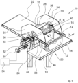
- numeral 10 indicates an apparatus for tipping boxes 12.
- the boxes 12 are used for transporting products 14 of various types in production, storage, sorting, packaging, shipping, etc. plants.
- the boxes 12 are usually made of plastic material and generally have a parallelepiped shape with an open upper face.
- Each box 12 has two upper longitudinal sides having respective outer edges 16 which protrude from the respective side walls.
- the boxes 12 advance along a longitudinal direction X on an inlet conveyor 18, for example, a belt conveyor.
- the inlet conveyor 18 transports each box 12 to a tipping station 20.
- the apparatus 10 picks up the box 12 which - in each case - is located in the tipping station 20 and overturns it in the manner which will be described below. During the overturning of each box 12, the products 14 come out of the upper open face of the box 12 and are collected on an outlet conveyor 22.
- the tipping apparatus 10 comprises a stationary support structure 24 and a chute 26 fixed with respect to the stationary support structure 24.
- the chute 26 comprises an inclined surface 28 having an upper edge 30 and a lower edge 32.
- the lower edge 32 is located above the outlet conveyor 22.
- the chute 26 may have a pair of lateral sides 34 which extend on opposite sides of the inclined surface 28.
- the tipping apparatus 10 comprises a movable support 36 rotatable with respect to the stationary support structure 24 around a first axis A parallel to the longitudinal direction X along which the boxes 12 move as they advance towards the tipping station 20.
- the tipping apparatus 10 comprises two tipping arms 38 carried by the movable support 36 and jointly rotatable with respect to the movable support 36 about a second axis B parallel to the first axis A.
- the tipping arms 38 may be connected to each other by a shaft 40, which may extend along the second axis B.
- the tipping arms 38 are parallel to each other and extend along a transverse direction Y perpendicular to the longitudinal direction X.
- the tipping arms 38 are located inside the lateral sides 34 of the chute 26.
- the tipping arms 38 carry a first and a second guide 42, 44, which extend parallel to the longitudinal direction X.
- the first and second guides 42, 44 have a C-shaped cross-section and are configured to engage their respective edges 16 of a box 12 when the box, advancing along the inlet conveyor 18, enters the tipping station 20.
- the first and second guides 42, 44 may have respective inlet sections 46 to facilitate the insertion of the outer edges 16 of a box 12 inside the guides 42, 44.
- the tipping apparatus 10 comprises a drive unit 48 configured to control the rotation of the movable support 36 relative to the stationary support structure 24 about the first axis A, and the rotation of the tipping arms 38 relative to the movable support 36 about the second axis B independently of each other.
- the drive unit 48 comprises a first rotary motor 50 carried by the stationary support structure 24 and arranged to control the rotation of the movable support 36 with respect to the stationary support structure 24 around said first axis A.
- the drive unit 48 may comprise a second rotary motor 52 carried by the movable support 36 and arranged to control the joint rotation of the two tipping arms 38 with respect to the movable support 36 about the second axis B.
- the first and second motors 50, 52 may be associated with respective reducers.
- the apparatus 10 may comprise an electronic control unit 54 which controls the first and second motors 50, 52 in a mutually coordinated manner.
- the operation of the tipping apparatus 10 is as follows.
- the apparatus 10 is in a pick-up position in which the tipping arms 38 extend above the inlet conveyor 18.
- the first and second guides 42, 44 are at the same distance from the inlet conveyor 18.
- a box 12 containing products 14 advances in the longitudinal direction X along the inlet conveyor 18.
- the outer edges 16 of the box 12 fit into the respective guides 42, 44.
- the movement in the longitudinal direction X of the box 12 stops when the box 12 is located between the two tipping arms 38.
- sensors could be provided which detect the position of the box 12 and stop the inlet conveyor 18 when the box 12 is in the correct position.
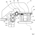
- the movable support 36 is driven to rotate about the first axis A in a first direction (counterclockwise in the representation of Figures 2 , 3 and 4 ) and the tipping arms 38 are driven to rotate around the second axis B with respect to the movable support 36 in a second direction opposite to the first direction (clockwise in the representation of Figures 2 , 3 , 4 ) .
- This actuation in opposite directions of the movable support 36 and of the tipping arms 38 causes a movement of the tipping arms 38 and of the box 12 along a straight direction C inclined upwards, so as to approach a longitudinal side of the box 12 with the upper edge 30 of the chute 26.
- This approach movement of the box 12 to the upper edge 30 of the chute 26 takes place without tipping the box 12, so as to avoid the risk that the products come out of the box before the box 12 is approached to the chute 26.
- the box 12 When the box 12 reaches the position illustrated with a dashed line in Figure 3 , the box 12 is located between the lateral sides 34 of the chute 26.
- the tipping of the box 12 begins, as shown in Figure 4 .
- the movable support 36 remains stationary and the tipping arms 38 rotate with respect to the movable support 36 around the second axis B.
- the rotation of the tipping arms 38 around the axis B continues until the tipping position shown in Figures 4 and 5 is reached.
- the rotation angle of the box between the pick-up position and the tipping position may be between 90° - 150°.
- the box 12 in the tipping position, the box 12 may be rotated by 115° with respect to the pick-up position.
- the products 14 come out of the box 12 by gravity through the open upper face, slide on the inclined surface 28 of the chute 26 and reach the outlet conveyor 22 where they are transported in the Y direction.
- the lateral sides 34 prevent the products 14 from falling from the side edges of the chute 26.
- the approach movement without rotation of the box 12 to the upper edge 30 of the chute 26 prevents the escaping of products 14 from the box 12 in the space between the box 12 and the upper edge 30 of the chute 26.
- the tipping arms 38 and the movable support 36 rotate around the respective axes B and A to bring the empty box back onto the inlet conveyor 18, where it is transported out of the tipping station 20. Then, a new box 12 is placed in the tipping station 20 for a new cycle. The return of the box 12 to its initial position may take place by simultaneously operating the tipping arms 38 and the main plate 36 to reduce the cycle time.
- Figure 6 illustrates a second embodiment of an apparatus for tipping boxes according to the present invention.
- the elements corresponding to those previously described are indicated with the same numeral references.
- the drive unit 48 comprises a single motor 60 carried by the stationary support structure 24 and associated with a transmission mechanism 62 which transmits a translational and rotational movement to the movable support 36.
- the transmission mechanism 62 comprises a guide plate 64 fixed with respect to the stationary support structure 24 and having a first guide 66 and a second guide 68 parallel to each other and inclined with respect to a vertical direction.
- the first guide 66 and the second guide 68 may be formed by respective straight slots.
- the first guide 66 has a closed upper end and the second guide 68 has an open upper end.
- the movable support 36 may have the shape of a plate to which the tipping arms 38 are attached.
- the movable support 36 has a first engagement element 72 and a second engagement element 74, formed for example by pins, configured to engage, respectively, the first guide 66 and the second guide 68 of the guide plate 64.
- the transmission mechanism 62 comprises an arm 76 fixed to the outlet shaft of the motor 60 and carrying a third engagement element 78 at its distal end - formed for example by a pin - which engages a third guide 80 - formed for example by a straight slot - formed in the movable support 36.
- the transmission mechanism 62 may comprise an elastic element 82 which elastically pushes the third engagement element 78 towards the upper end of the first guide 66.
- the engagement elements 72, 74 engage the respective guides 66, 68 of the guide plate 64 and are located near the lower ends of the guides 66, 68.
- the motor 60 rotates the arm 76 which, through the third engagement element 78 engaged in the third guide 80, commands an upward movement of the movable support 36.
- the movable support 36 and the box 12 move with a translational movement along a straight direction C inclined upwards.
- the second engagement element 74 reaches the upper end of the second guide 68 and disengages from the second guide 68 while the first engagement element 72 remains engaged with the upper end of the first guide 66.
- the further rotation of the arm 76 commands a rotation of the movable support 36 around an axis A passing through the first engagement element 72.
- the rotation of the movable support 36 around the axis A produces the tipping of the box 12.
- the arm 76 is rotated in the opposite direction, so as to bring the second engagement element 74 of the movable support 36 back into engagement with the upper end of the second guide 68 and up to depositing the empty box 12 on the inlet conveyor 18.
- the cover of the upper open face of the box 12 with a door is not provided. Therefore, the tipping cycle may begin immediately after a full box enters the tipping station 20. This allows considerable reduction of the cycle time.
- the tipping arc of the box is considerably smaller than in solutions according to the prior art, which further reduces the cycle time.
- the return movement of the box from the overturned position towards the initial position contributes to the transfer of the products onto the chute. Therefore, the return movement must be controlled and cannot be performed at high speed.
- the products are completely overturned onto the chute at the end of the tipping of the box, so that the return movement may be performed more quickly, which further contributes to a reduction in the cycle time.
- a particularly advantageous characteristic of the solution according to the present invention is that the combination of the two rotational movements around the axes A and B generates a movement profile very similar to that which would be implemented by an operator who had to manually perform the tipping, minimizing the forces involved.
Landscapes
- Engineering & Computer Science (AREA)
- Mechanical Engineering (AREA)
- Discharge Of Articles From Conveyors (AREA)
- Attitude Control For Articles On Conveyors (AREA)
Abstract
- a stationary support structure (24),
- a chute (26) fixed with respect to the stationary support structure (24),
- a movable support (36) carrying two tipping arms (38), and
- a drive unit (48) configured to move the tipping arms (38) along a straight direction (C) inclined with respect to a vertical direction, and to rotate the tipping arms (38) around an axis (A, B) parallel to a longitudinal direction (X).
Description
- The present invention generally relates to the automatic handling of products.
- More specifically, the invention relates to an apparatus for tipping boxes.
- The invention has been developed in particular with a view to the automatic handling of products in production plants, automatic warehouses, shipping centers, etc., where operations of storage, sorting, distribution, packaging, shipping, etc. are carried out.
- The invention was developed in particular with a view to its application in shipping centers for products sold through e-commerce channels.
- In storage, sorting, packaging and shipping systems, boxes are frequently used for transporting products. The boxes containing the products are generally handled by roller or belt conveyors. When a box reaches its destination, the products contained therein are unloaded for further processing.
- The emptying of the boxes may be carried out by tipping devices, which pick up the boxes and overturn them so as to release the products from the open upper sides of the boxes.
-
US 11 104 527 B1 - The box tipping system described in
US 11 104 527 B1 - the closing operation of the boxes with the door must necessarily be carried out before starting the tipping of the box;
- to empty the box on the door, the box must make a very wide rotation (about 180°);
- between the center of rotation of the tipping arms and the box there is a very long arm which prevents too rapid rotations, otherwise the accelerations and the consequent mechanical stresses would be too high.
- Consequently, the tipping cycle of a box is quite long, in the order of about 10 seconds.
- Furthermore, the tipping system described in
US 11 104 527 B1 - The present invention aims to provide an apparatus for tipping boxes that overcomes the problems of the prior art.
- According to the present invention, this object is achieved by an apparatus having the characteristics forming the subject of claims 1 or 4.
- Preferred embodiments of the invention form the subject of the dependent claims.
- The claims form an integral part of the disclosure provided here in relation to the invention.
- The present invention will now be described in detail with reference to the attached drawings, given purely by way of non-limiting example, wherein:
-
Figure 1 is a schematic perspective view of an apparatus for tipping boxes according to an embodiment of the present invention, -
Figures 2 ,3 and4 are schematic side views illustrating the tipping sequence of a box, -
Figure 5 is a perspective view illustrating the apparatus in the tipping position, and -
Figure 6 is a schematic side view illustrating a second embodiment of an apparatus for tipping boxes according to the present invention, - It will be appreciated that the accompanying drawings are schematic and that some components may not be shown to assist in understanding the Figures. Also, it will be appreciated that the various figures may not be represented on the same scale.
- With reference to
Figures 1-5 ,numeral 10 indicates an apparatus for tippingboxes 12. - The
boxes 12 are used for transportingproducts 14 of various types in production, storage, sorting, packaging, shipping, etc. plants. Theboxes 12 are usually made of plastic material and generally have a parallelepiped shape with an open upper face. Eachbox 12 has two upper longitudinal sides having respectiveouter edges 16 which protrude from the respective side walls. With reference toFigure 1 , theboxes 12 advance along a longitudinal direction X on aninlet conveyor 18, for example, a belt conveyor. Theinlet conveyor 18 transports eachbox 12 to atipping station 20. - The
apparatus 10 picks up thebox 12 which - in each case - is located in thetipping station 20 and overturns it in the manner which will be described below. During the overturning of eachbox 12, theproducts 14 come out of the upper open face of thebox 12 and are collected on anoutlet conveyor 22. - The tipping
apparatus 10 comprises astationary support structure 24 and achute 26 fixed with respect to thestationary support structure 24. Thechute 26 comprises aninclined surface 28 having anupper edge 30 and alower edge 32. Thelower edge 32 is located above theoutlet conveyor 22. Thechute 26 may have a pair oflateral sides 34 which extend on opposite sides of theinclined surface 28. - The tipping
apparatus 10 comprises amovable support 36 rotatable with respect to thestationary support structure 24 around a first axis A parallel to the longitudinal direction X along which theboxes 12 move as they advance towards thetipping station 20. - The tipping
apparatus 10 comprises two tippingarms 38 carried by themovable support 36 and jointly rotatable with respect to themovable support 36 about a second axis B parallel to the first axis A. The tippingarms 38 may be connected to each other by ashaft 40, which may extend along the second axis B. The tippingarms 38 are parallel to each other and extend along a transverse direction Y perpendicular to the longitudinal direction X. The tippingarms 38 are located inside thelateral sides 34 of thechute 26. The tippingarms 38 carry a first and asecond guide second guides respective edges 16 of abox 12 when the box, advancing along theinlet conveyor 18, enters thetipping station 20. The first andsecond guides respective inlet sections 46 to facilitate the insertion of theouter edges 16 of abox 12 inside theguides - The
tipping apparatus 10 comprises adrive unit 48 configured to control the rotation of themovable support 36 relative to thestationary support structure 24 about the first axis A, and the rotation of the tippingarms 38 relative to themovable support 36 about the second axis B independently of each other. - In one possible embodiment, the
drive unit 48 comprises a firstrotary motor 50 carried by thestationary support structure 24 and arranged to control the rotation of themovable support 36 with respect to thestationary support structure 24 around said first axis A. - The
drive unit 48 may comprise a secondrotary motor 52 carried by themovable support 36 and arranged to control the joint rotation of the two tippingarms 38 with respect to themovable support 36 about the second axis B. The first andsecond motors - The
apparatus 10 may comprise anelectronic control unit 54 which controls the first andsecond motors - The operation of the tipping
apparatus 10 is as follows. - In a first step, illustrated in
Figure 2 , theapparatus 10 is in a pick-up position in which the tippingarms 38 extend above theinlet conveyor 18. The first andsecond guides inlet conveyor 18. Abox 12 containingproducts 14 advances in the longitudinal direction X along theinlet conveyor 18. When thebox 12 enters thetipping station 20, theouter edges 16 of thebox 12 fit into therespective guides box 12 stops when thebox 12 is located between the two tippingarms 38. For example, sensors could be provided which detect the position of thebox 12 and stop theinlet conveyor 18 when thebox 12 is in the correct position. - At this point, as shown in
Figure 3 , themovable support 36 is driven to rotate about the first axis A in a first direction (counterclockwise in the representation ofFigures 2 ,3 and4 ) and the tippingarms 38 are driven to rotate around the second axis B with respect to themovable support 36 in a second direction opposite to the first direction (clockwise in the representation ofFigures 2 ,3 ,4 ) . This actuation in opposite directions of themovable support 36 and of the tippingarms 38 causes a movement of the tippingarms 38 and of thebox 12 along a straight direction C inclined upwards, so as to approach a longitudinal side of thebox 12 with theupper edge 30 of thechute 26. This approach movement of thebox 12 to theupper edge 30 of thechute 26 takes place without tipping thebox 12, so as to avoid the risk that the products come out of the box before thebox 12 is approached to thechute 26. - When the
box 12 reaches the position illustrated with a dashed line inFigure 3 , thebox 12 is located between thelateral sides 34 of thechute 26. - At this point, the tipping of the
box 12 begins, as shown inFigure 4 . In this step, themovable support 36 remains stationary and the tippingarms 38 rotate with respect to themovable support 36 around the second axis B. The rotation of the tippingarms 38 around the axis B continues until the tipping position shown inFigures 4 and5 is reached. - The rotation angle of the box between the pick-up position and the tipping position may be between 90° - 150°. For example, in the tipping position, the
box 12 may be rotated by 115° with respect to the pick-up position. - In the tipping position, the
products 14 come out of thebox 12 by gravity through the open upper face, slide on theinclined surface 28 of thechute 26 and reach theoutlet conveyor 22 where they are transported in the Y direction. - The lateral sides 34 prevent the
products 14 from falling from the side edges of thechute 26. The approach movement without rotation of thebox 12 to theupper edge 30 of thechute 26 prevents the escaping ofproducts 14 from thebox 12 in the space between thebox 12 and theupper edge 30 of thechute 26. - When the emptying of the
box 12 has finished, the tippingarms 38 and themovable support 36 rotate around the respective axes B and A to bring the empty box back onto theinlet conveyor 18, where it is transported out of thetipping station 20. Then, anew box 12 is placed in thetipping station 20 for a new cycle. The return of thebox 12 to its initial position may take place by simultaneously operating the tippingarms 38 and themain plate 36 to reduce the cycle time. -
Figure 6 illustrates a second embodiment of an apparatus for tipping boxes according to the present invention. The elements corresponding to those previously described are indicated with the same numeral references. - With reference to
Figure 6 , thedrive unit 48 comprises asingle motor 60 carried by thestationary support structure 24 and associated with atransmission mechanism 62 which transmits a translational and rotational movement to themovable support 36. - The
transmission mechanism 62 comprises aguide plate 64 fixed with respect to thestationary support structure 24 and having afirst guide 66 and asecond guide 68 parallel to each other and inclined with respect to a vertical direction. Thefirst guide 66 and thesecond guide 68 may be formed by respective straight slots. Thefirst guide 66 has a closed upper end and thesecond guide 68 has an open upper end. - In the embodiment of
Figure 6 , themovable support 36 may have the shape of a plate to which the tippingarms 38 are attached. Themovable support 36 has afirst engagement element 72 and asecond engagement element 74, formed for example by pins, configured to engage, respectively, thefirst guide 66 and thesecond guide 68 of theguide plate 64. - The
transmission mechanism 62 comprises an arm 76 fixed to the outlet shaft of themotor 60 and carrying athird engagement element 78 at its distal end - formed for example by a pin - which engages a third guide 80 - formed for example by a straight slot - formed in themovable support 36. - The
transmission mechanism 62 may comprise anelastic element 82 which elastically pushes thethird engagement element 78 towards the upper end of thefirst guide 66. - During operation, in a pick-up position, the
engagement elements guide plate 64 and are located near the lower ends of theguides - After a
box 12 has engaged theguides arms 38, themotor 60 rotates the arm 76 which, through thethird engagement element 78 engaged in thethird guide 80, commands an upward movement of themovable support 36. - As long as the
first engagement element 72 and thesecond engagement element 74 are engaged in the respective guides 66, 68, themovable support 36 and thebox 12 move with a translational movement along a straight direction C inclined upwards. Continuing the rotation of the arm 76, thesecond engagement element 74 reaches the upper end of thesecond guide 68 and disengages from thesecond guide 68 while thefirst engagement element 72 remains engaged with the upper end of thefirst guide 66. At this point, the further rotation of the arm 76 commands a rotation of themovable support 36 around an axis A passing through thefirst engagement element 72. The rotation of themovable support 36 around the axis A produces the tipping of thebox 12. - Once the tipping of the
box 12 has been completed, the arm 76 is rotated in the opposite direction, so as to bring thesecond engagement element 74 of themovable support 36 back into engagement with the upper end of thesecond guide 68 and up to depositing theempty box 12 on theinlet conveyor 18. - The embodiment of
Figures 1-5 and the embodiment ofFigure 6 both relate to an apparatus for tipping boxes, comprising: - a
stationary support structure 24, - a
chute 26 fixed with respect to thestationary support structure 24 and including aninclined surface 28 having anupper edge 30 and alower edge 32, - a
movable support 36 carrying two tippingarms 38, wherein the tippingarms 38 carry a first and asecond guide outer edges 16 of abox 12, and - a
drive unit 48 configured to move said tippingarms 38 with respect to thestationary support structure 24 along a straight direction C inclined with respect to a vertical direction and to rotate the tippingarms 38 with respect to thestationary support structure 24 around an axis A, B parallel to said longitudinal direction X. - In the solutions according to the present invention, the cover of the upper open face of the
box 12 with a door is not provided. Therefore, the tipping cycle may begin immediately after a full box enters thetipping station 20. This allows considerable reduction of the cycle time. - The tipping arc of the box is considerably smaller than in solutions according to the prior art, which further reduces the cycle time.
- In the solutions according to the prior art, the return movement of the box from the overturned position towards the initial position contributes to the transfer of the products onto the chute. Therefore, the return movement must be controlled and cannot be performed at high speed. In the solutions according to the present invention, the products are completely overturned onto the chute at the end of the tipping of the box, so that the return movement may be performed more quickly, which further contributes to a reduction in the cycle time.
- All these characteristics combine to obtain more efficient dynamics of the tipping system, which requires less energy and lower torques thanks to lower rotation angles and smaller rotation arms that are closer to the box (lower torque/power demand).
- A particularly advantageous characteristic of the solution according to the present invention is that the combination of the two rotational movements around the axes A and B generates a movement profile very similar to that which would be implemented by an operator who had to manually perform the tipping, minimizing the forces involved.
- Of course, without prejudice to the principle of the invention, the details of construction and the embodiments can be widely varied with respect to those described and illustrated, without thereby departing from the scope of the invention as defined by the claims that follow.
Claims (7)
- An apparatus for tipping boxes, comprising:- a stationary support structure (24),- a chute (26) fixed with respect to the stationary support structure (24) and including an inclined surface (28) having an upper edge (30) and a lower edge (32),- a movable support (36) carrying two tipping arms (38), wherein the tipping arms (38) carry a first and a second guide (42, 44) extending parallel to a longitudinal direction (X) and configured to engage respective outer edges (16) of a box (12), and- a drive unit (48) configured to move said tipping arms (38) with respect to the stationary support structure (24) along a straight direction (C) inclined with respect to a vertical direction and to rotate the tipping arms (38) with respect to the stationary support structure (24) around an axis (A, B) parallel to said longitudinal direction (X),wherein the movable support (36) is rotatable with respect to the stationary support structure (24) about a first axis (A) parallel to said longitudinal direction (X), and wherein the tipping arms (38) are rotatable jointly with respect to the movable support (36) around a second axis (B) parallel to said first axis (A), and wherein the drive unit (48) is configured to control the rotation of the movable support (36) with respect to the stationary support structure (24) around said first axis (A) and the rotation of the tipping arms (38) with respect to the movable support (36) around said second axis (B) independently from each other,wherein said drive unit (48) comprises a first rotary motor (50) fixed with respect to said stationary support structure (24) and arranged to control the rotation of said movable support (36) with respect to the stationary support structure (24) around said first axis (A), andwherein said drive unit (48) comprises a second rotary motor (52) carried by said movable support (36) and arranged to control the rotation of said tipping arms (38) with respect to the movable support (36) around said second axis (B).
- An apparatus according to claim 1, wherein said drive unit (48) is controlled to actuate the movable support (36) and the tipping arms (38) in opposite directions to each other so as to move the box (20) along said straight direction (C) up to a position wherein an upper edge of the box (12) is adjacent to the upper edge (30) of said chute (26).
- An apparatus according to claim 1 or claim 2, wherein said drive unit (48) is controlled to stop the rotation of said movable support (36) and to control the rotation of said tipping arms (38) so as to overturn the box (20) around said second axis (B).
- An apparatus for tipping boxes, comprising:- a stationary support structure (24),- a chute (26) fixed with respect to the stationary support structure (24) and including an inclined surface (28) having an upper edge (30) and a lower edge (32),- a movable support (36) carrying two tipping arms (38), wherein the tipping arms (38) carry a first and a second guide (42, 44) extending parallel to a longitudinal direction (X) and configured to engage respective outer edges (16) of a box (12), and- a drive unit (48) configured to move said tipping arms (38) with respect to the stationary support structure (24) along a straight direction (C) inclined with respect to a vertical direction and to rotate the tipping arms (38) with respect to the stationary support structure (24) around an axis (A, B) parallel to said longitudinal direction (X),wherein said tipping arms (38) are fixed with respect to the movable support (36) and wherein said drive unit (48) comprises a single motor (60) carried by the stationary support structure (24) and associated with a transmission mechanism (62) comprising a guide plate (64) fixed with respect to the stationary support structure (24) and arranged to guide the movable support (36) along said straight direction (C).
- An apparatus according to claim 4, wherein said transmission mechanism (62) comprises an arm (76) fixed to an outlet shaft of the motor (60) and carrying a third engagement element (78) at its distal end, which engages a third guide (80) formed in the movable support (36).
- An apparatus according to any one of the preceding claims, wherein said chute (26) comprises a pair of lateral sides (34) located on opposite sides of said inclined surface (28) and wherein said tipping arms (38) extend inside with respect to said lateral sides (34).
- An apparatus according to any one of the preceding claims, comprising an inlet conveyor (18) arranged to advance the boxes (12) in a longitudinal direction (X) and an outlet conveyor arranged to advance the products released from the boxes (12) along a transverse direction (Y) perpendicular to said longitudinal direction (X).
Applications Claiming Priority (1)
| Application Number | Priority Date | Filing Date | Title |
|---|---|---|---|
| IT102022000016365A IT202200016365A1 (en) | 2022-08-02 | 2022-08-02 | Crate tipping device |
Publications (3)
| Publication Number | Publication Date |
|---|---|
| EP4339142A1 true EP4339142A1 (en) | 2024-03-20 |
| EP4339142C0 EP4339142C0 (en) | 2025-04-16 |
| EP4339142B1 EP4339142B1 (en) | 2025-04-16 |
Family
ID=83691058
Family Applications (1)
| Application Number | Title | Priority Date | Filing Date |
|---|---|---|---|
| EP23184777.3A Active EP4339142B1 (en) | 2022-08-02 | 2023-07-11 | An apparatus for tipping boxes |
Country Status (3)
| Country | Link |
|---|---|
| US (1) | US20240043230A1 (en) |
| EP (1) | EP4339142B1 (en) |
| IT (1) | IT202200016365A1 (en) |
Families Citing this family (3)
| Publication number | Priority date | Publication date | Assignee | Title |
|---|---|---|---|---|
| US20240294343A1 (en) * | 2023-03-03 | 2024-09-05 | Material Handling Systems, Inc. | Tote tipping system |
| CN118047201B (en) * | 2024-04-07 | 2025-03-07 | 池州市千润宇信息技术有限公司 | High-efficient conveying equipment that photovoltaic board processing was used |
| CN119278762B (en) * | 2024-12-05 | 2025-02-28 | 辽宁辽拓大益农业机械股份有限公司 | Lifting type corn harvester granary structure |
Citations (5)
| Publication number | Priority date | Publication date | Assignee | Title |
|---|---|---|---|---|
| US3342358A (en) * | 1965-12-15 | 1967-09-19 | Dempster Brothers Inc | Container dumping devices |
| CN201758718U (en) * | 2010-09-17 | 2011-03-16 | 嘉兴市瑞邦机械工程有限公司 | Feeder |
| US20120207566A1 (en) * | 2011-02-16 | 2012-08-16 | Albert Handtmann Maschinenfabrik Gmbh & Co. Kg | Device and method for loading a food processing machine, in particular a filling machine or a cutter, with food |
| CN112849860A (en) * | 2020-12-31 | 2021-05-28 | 华南理工大学 | Garbage dumping mechanical arm and household robot with same |
| US11104527B1 (en) | 2019-02-04 | 2021-08-31 | Amazon Technologies, Inc. | Tote flipper |
Family Cites Families (9)
| Publication number | Priority date | Publication date | Assignee | Title |
|---|---|---|---|---|
| US2321300A (en) * | 1942-08-03 | 1943-06-08 | Eaton Mfg Co | Mechanical handling device |
| US3978999A (en) * | 1974-11-08 | 1976-09-07 | Rohr Plessey Corporation | Container discharge damage reduction flap |
| US4447185A (en) * | 1979-10-11 | 1984-05-08 | Mhlume (Swaziland) Sugar Company Limited | Container tipping apparatus |
| US4422814A (en) * | 1981-06-02 | 1983-12-27 | Applied Products, Inc. | Ground level dump unit |
| US4597710A (en) * | 1984-11-28 | 1986-07-01 | Athey Products Corporation | Trash collection vehicle side-loading apparatus |
| DE3812931A1 (en) * | 1988-04-18 | 1989-10-26 | Handtmann Albert Maschf | MEAT PROCESSING MACHINE |
| US5895196A (en) * | 1998-02-12 | 1999-04-20 | Forsyth; Rodney J. | Mixing bowl lift apparatus and method |
| US6012891A (en) * | 1998-06-26 | 2000-01-11 | Chrysler Corporation | Parts handling apparatus |
| AU2010200047B1 (en) * | 2010-01-06 | 2010-05-13 | Wrightway Eco Products Pty Ltd | Apparatus for Inverting an Object |
-
2022
- 2022-08-02 IT IT102022000016365A patent/IT202200016365A1/en unknown
-
2023
- 2023-07-11 EP EP23184777.3A patent/EP4339142B1/en active Active
- 2023-07-31 US US18/362,304 patent/US20240043230A1/en active Pending
Patent Citations (5)
| Publication number | Priority date | Publication date | Assignee | Title |
|---|---|---|---|---|
| US3342358A (en) * | 1965-12-15 | 1967-09-19 | Dempster Brothers Inc | Container dumping devices |
| CN201758718U (en) * | 2010-09-17 | 2011-03-16 | 嘉兴市瑞邦机械工程有限公司 | Feeder |
| US20120207566A1 (en) * | 2011-02-16 | 2012-08-16 | Albert Handtmann Maschinenfabrik Gmbh & Co. Kg | Device and method for loading a food processing machine, in particular a filling machine or a cutter, with food |
| US11104527B1 (en) | 2019-02-04 | 2021-08-31 | Amazon Technologies, Inc. | Tote flipper |
| CN112849860A (en) * | 2020-12-31 | 2021-05-28 | 华南理工大学 | Garbage dumping mechanical arm and household robot with same |
Also Published As
| Publication number | Publication date |
|---|---|
| EP4339142C0 (en) | 2025-04-16 |
| US20240043230A1 (en) | 2024-02-08 |
| IT202200016365A1 (en) | 2024-02-02 |
| EP4339142B1 (en) | 2025-04-16 |
Similar Documents
| Publication | Publication Date | Title |
|---|---|---|
| EP4339142B1 (en) | An apparatus for tipping boxes | |
| EP2986446B1 (en) | Pouch collection robot system and method for the assembly and collection of non-filled spouted pouches | |
| AU2001294078B2 (en) | Apparatus and method for packaging products | |
| US11819998B2 (en) | Article transfer device | |
| EP2184233A2 (en) | Apparatus for packaging articles and method for same | |
| JPH0536283B2 (en) | ||
| US20030113195A1 (en) | Method and unit for feeding elongated elements | |
| EP3331762B1 (en) | Device for wrapping products | |
| US7191892B2 (en) | Apparatus for transferring products from a first conveying line to a second conveying line, in particular for feeding a boxing machine | |
| EP2501633B1 (en) | Rotatory slug loader | |
| US5454215A (en) | Case gripping device in an automatic packaging machine | |
| CN110386296B (en) | Device and method for transporting blister packs | |
| KR100662928B1 (en) | Carton sizing device | |
| CN110386291B (en) | Transfer unit and method for transferring blister packs | |
| JPH06312711A (en) | Stacking packer of boxed products | |
| US20090038264A1 (en) | Rotating-head machine for packaging products in sealed film | |
| JP4274895B2 (en) | Container alignment device | |
| JP4229801B2 (en) | Container transfer device | |
| CN113696246B (en) | Automatic cutting and packaging system for nano-plate | |
| CN110386292B (en) | Transfer unit and method for transferring blister packs | |
| CN115849043A (en) | Loading equipment and loading method for container | |
| JP4331098B2 (en) | Direction change device | |
| JP4141370B2 (en) | Cap tightening device | |
| EP4313779B1 (en) | Machine for packaging products of the tobacco industry, particularly snus | |
| EP1273539B1 (en) | Method and arrangement for loading or unloading roll containers |
Legal Events
| Date | Code | Title | Description |
|---|---|---|---|
| PUAI | Public reference made under article 153(3) epc to a published international application that has entered the european phase |
Free format text: ORIGINAL CODE: 0009012 |
|
| STAA | Information on the status of an ep patent application or granted ep patent |
Free format text: STATUS: THE APPLICATION HAS BEEN PUBLISHED |
|
| AK | Designated contracting states |
Kind code of ref document: A1 Designated state(s): AL AT BE BG CH CY CZ DE DK EE ES FI FR GB GR HR HU IE IS IT LI LT LU LV MC ME MK MT NL NO PL PT RO RS SE SI SK SM TR |
|
| STAA | Information on the status of an ep patent application or granted ep patent |
Free format text: STATUS: REQUEST FOR EXAMINATION WAS MADE |
|
| 17P | Request for examination filed |
Effective date: 20240729 |
|
| RBV | Designated contracting states (corrected) |
Designated state(s): AL AT BE BG CH CY CZ DE DK EE ES FI FR GB GR HR HU IE IS IT LI LT LU LV MC ME MK MT NL NO PL PT RO RS SE SI SK SM TR |
|
| GRAP | Despatch of communication of intention to grant a patent |
Free format text: ORIGINAL CODE: EPIDOSNIGR1 |
|
| STAA | Information on the status of an ep patent application or granted ep patent |
Free format text: STATUS: GRANT OF PATENT IS INTENDED |
|
| RIC1 | Information provided on ipc code assigned before grant |
Ipc: B65G 65/23 20060101AFI20241126BHEP |
|
| INTG | Intention to grant announced |
Effective date: 20241218 |
|
| GRAS | Grant fee paid |
Free format text: ORIGINAL CODE: EPIDOSNIGR3 |
|
| GRAA | (expected) grant |
Free format text: ORIGINAL CODE: 0009210 |
|
| STAA | Information on the status of an ep patent application or granted ep patent |
Free format text: STATUS: THE PATENT HAS BEEN GRANTED |
|
| AK | Designated contracting states |
Kind code of ref document: B1 Designated state(s): AL AT BE BG CH CY CZ DE DK EE ES FI FR GB GR HR HU IE IS IT LI LT LU LV MC ME MK MT NL NO PL PT RO RS SE SI SK SM TR |
|
| REG | Reference to a national code |
Ref country code: GB Ref legal event code: FG4D |
|
| REG | Reference to a national code |
Ref country code: CH Ref legal event code: EP Ref country code: DE Ref legal event code: R096 Ref document number: 602023002918 Country of ref document: DE |
|
| REG | Reference to a national code |
Ref country code: IE Ref legal event code: FG4D |
|
| U01 | Request for unitary effect filed |
Effective date: 20250502 |
|
| U07 | Unitary effect registered |
Designated state(s): AT BE BG DE DK EE FI FR IT LT LU LV MT NL PT RO SE SI Effective date: 20250508 |
|
| U20 | Renewal fee for the european patent with unitary effect paid |
Year of fee payment: 3 Effective date: 20250728 |
|
| PG25 | Lapsed in a contracting state [announced via postgrant information from national office to epo] |
Ref country code: ES Free format text: LAPSE BECAUSE OF FAILURE TO SUBMIT A TRANSLATION OF THE DESCRIPTION OR TO PAY THE FEE WITHIN THE PRESCRIBED TIME-LIMIT Effective date: 20250416 |
|
| PG25 | Lapsed in a contracting state [announced via postgrant information from national office to epo] |
Ref country code: GR Free format text: LAPSE BECAUSE OF FAILURE TO SUBMIT A TRANSLATION OF THE DESCRIPTION OR TO PAY THE FEE WITHIN THE PRESCRIBED TIME-LIMIT Effective date: 20250717 Ref country code: NO Free format text: LAPSE BECAUSE OF FAILURE TO SUBMIT A TRANSLATION OF THE DESCRIPTION OR TO PAY THE FEE WITHIN THE PRESCRIBED TIME-LIMIT Effective date: 20250716 |
|
| PG25 | Lapsed in a contracting state [announced via postgrant information from national office to epo] |
Ref country code: PL Free format text: LAPSE BECAUSE OF FAILURE TO SUBMIT A TRANSLATION OF THE DESCRIPTION OR TO PAY THE FEE WITHIN THE PRESCRIBED TIME-LIMIT Effective date: 20250416 |
|
| PG25 | Lapsed in a contracting state [announced via postgrant information from national office to epo] |
Ref country code: HR Free format text: LAPSE BECAUSE OF FAILURE TO SUBMIT A TRANSLATION OF THE DESCRIPTION OR TO PAY THE FEE WITHIN THE PRESCRIBED TIME-LIMIT Effective date: 20250416 |
|
| PG25 | Lapsed in a contracting state [announced via postgrant information from national office to epo] |
Ref country code: RS Free format text: LAPSE BECAUSE OF FAILURE TO SUBMIT A TRANSLATION OF THE DESCRIPTION OR TO PAY THE FEE WITHIN THE PRESCRIBED TIME-LIMIT Effective date: 20250716 |
|
| PG25 | Lapsed in a contracting state [announced via postgrant information from national office to epo] |
Ref country code: IS Free format text: LAPSE BECAUSE OF FAILURE TO SUBMIT A TRANSLATION OF THE DESCRIPTION OR TO PAY THE FEE WITHIN THE PRESCRIBED TIME-LIMIT Effective date: 20250816 |
|
| PG25 | Lapsed in a contracting state [announced via postgrant information from national office to epo] |
Ref country code: SM Free format text: LAPSE BECAUSE OF FAILURE TO SUBMIT A TRANSLATION OF THE DESCRIPTION OR TO PAY THE FEE WITHIN THE PRESCRIBED TIME-LIMIT Effective date: 20250416 |
|
| PG25 | Lapsed in a contracting state [announced via postgrant information from national office to epo] |
Ref country code: CZ Free format text: LAPSE BECAUSE OF FAILURE TO SUBMIT A TRANSLATION OF THE DESCRIPTION OR TO PAY THE FEE WITHIN THE PRESCRIBED TIME-LIMIT Effective date: 20250416 |
|
| PG25 | Lapsed in a contracting state [announced via postgrant information from national office to epo] |
Ref country code: SK Free format text: LAPSE BECAUSE OF FAILURE TO SUBMIT A TRANSLATION OF THE DESCRIPTION OR TO PAY THE FEE WITHIN THE PRESCRIBED TIME-LIMIT Effective date: 20250416 |
|
| PLBE | No opposition filed within time limit |
Free format text: ORIGINAL CODE: 0009261 |
|
| STAA | Information on the status of an ep patent application or granted ep patent |
Free format text: STATUS: NO OPPOSITION FILED WITHIN TIME LIMIT |
|
| REG | Reference to a national code |
Ref country code: CH Ref legal event code: L10 Free format text: ST27 STATUS EVENT CODE: U-0-0-L10-L00 (AS PROVIDED BY THE NATIONAL OFFICE) Effective date: 20260225 |
|
| 26N | No opposition filed |
Effective date: 20260119 |