EP4339079A1 - Car - Google Patents
Car Download PDFInfo
- Publication number
- EP4339079A1 EP4339079A1 EP23196213.5A EP23196213A EP4339079A1 EP 4339079 A1 EP4339079 A1 EP 4339079A1 EP 23196213 A EP23196213 A EP 23196213A EP 4339079 A1 EP4339079 A1 EP 4339079A1
- Authority
- EP
- European Patent Office
- Prior art keywords
- car
- driving engine
- movable portion
- fixed
- peripheral edge
- Prior art date
- Legal status (The legal status is an assumption and is not a legal conclusion. Google has not performed a legal analysis and makes no representation as to the accuracy of the status listed.)
- Pending
Links
- 230000002093 peripheral effect Effects 0.000 claims description 11
- 239000006096 absorbing agent Substances 0.000 claims description 4
- 230000035939 shock Effects 0.000 claims description 4
- 230000005484 gravity Effects 0.000 description 2
- 230000005540 biological transmission Effects 0.000 description 1
- 239000000463 material Substances 0.000 description 1
- 230000000149 penetrating effect Effects 0.000 description 1
Images




Classifications
-
- B—PERFORMING OPERATIONS; TRANSPORTING
- B62—LAND VEHICLES FOR TRAVELLING OTHERWISE THAN ON RAILS
- B62D—MOTOR VEHICLES; TRAILERS
- B62D35/00—Vehicle bodies characterised by streamlining
- B62D35/02—Streamlining the undersurfaces
-
- B—PERFORMING OPERATIONS; TRANSPORTING
- B60—VEHICLES IN GENERAL
- B60K—ARRANGEMENT OR MOUNTING OF PROPULSION UNITS OR OF TRANSMISSIONS IN VEHICLES; ARRANGEMENT OR MOUNTING OF PLURAL DIVERSE PRIME-MOVERS IN VEHICLES; AUXILIARY DRIVES FOR VEHICLES; INSTRUMENTATION OR DASHBOARDS FOR VEHICLES; ARRANGEMENTS IN CONNECTION WITH COOLING, AIR INTAKE, GAS EXHAUST OR FUEL SUPPLY OF PROPULSION UNITS IN VEHICLES
- B60K5/00—Arrangement or mounting of internal-combustion or jet-propulsion units
- B60K5/12—Arrangement of engine supports
- B60K5/1208—Resilient supports
-
- B—PERFORMING OPERATIONS; TRANSPORTING
- B62—LAND VEHICLES FOR TRAVELLING OTHERWISE THAN ON RAILS
- B62D—MOTOR VEHICLES; TRAILERS
- B62D37/00—Stabilising vehicle bodies without controlling suspension arrangements
- B62D37/02—Stabilising vehicle bodies without controlling suspension arrangements by aerodynamic means
Definitions
- the invention relates to a car.
- the invention relates to a car of the kind comprising a support frame defining part of a lower floor of the car; a passenger compartment mounted on the support frame and projecting upwards from the lower floor; a driving engine to move the car; and an aerodynamic bottom fixed to the support frame and defining part of the lower floor.
- the driving engine is mounted in a central rear area of the car and is fixed to the support frame through the interposition of an elastic shock absorber device, which allows the driving engine to move relative to the lower floor during the normal operation of the car.
- the driving engine In order to allow the driving engine to move relative to the lower floor, the driving engine is fixed to the support frame at a given distance from the lower floor itself.
- the object of the invention is to provide a car designed to eliminate the aforementioned drawbacks in a straightforward, relatively low-cost manner.
- number 1 indicates, as a whole, a car, in particular a sports car, comprising a support frame 2 defining part of a lower floor 3 of the car 1.
- the car 1 further comprises a passenger compartment 4, which is mounted on the frame 2 and projects upwards from the floor 3, and an aerodynamic bottom 5, which is partly fixed to the frame 2 and defines part of the floor 3.
- the bottom 5 comprises a front bottom 6, which is fixed to the frame 2 in a front area 7 of the car 1, a rear bottom 8, which is mounted in a rear area 9 of the car 1, and an elongated central bottom 10, which is fixed to the frame 2 between the bottoms 6 and 8 and in a central area 11 of the car 1.
- the car 1 further comprises a driving engine 12, which is mounted at the centre of the rear area 9 and is connected to the frame 2 through the interposition of a known elastic shock absorber device, which is not shown herein, so as to have at least one degree of freedom relative to the frame 2 during the normal operation of the car 1.
- the engine 12 comprises a crankcase 13, a cylinder head 14 facing the floor 3 and a transmission shaft 15 and is oriented so that the cylinder head 14 is arranged under the shaft 15.
- the rear bottom 8 comprises a fixed portion 16, which has an annular shape, is fixed to the frame 2 and is provided with a central opening 17 with a substantially rectangular shape, and a movable portion 18, which has the shape of a substantially rectangular tank and is fixed under the cylinder head 14.
- the assembly defined by the engine 12 and by the portion 18 is movable relative to the frame 2 during the normal operation of the car 1.
- the portion 18 is delimited by a bottom wall 19, which is substantially coplanar to the portion 16, is fixed to the cylinder head 14 and is provided with an outer peripheral edge 20.
- the edge 20 projects upwards from the wall 19, is bent on top of and along an inner peripheral edge 21 of the opening 17 and is arranged at a distance from the edge 21 so as to allow air to flow along the floor 3 and prevent air from penetrating between the edges 20 and 21.
- FIG 6 differs from figures 3 and 5 only in that, in it, the movable portion 18 is eliminated and replaced by a movable portion 22, which has the shape of a substantially rectangular plate, extends inside the opening 17 and is substantially coplanar to the portion 16.
- the portion 22 has an outer peripheral edge 23 connected to the edge 21 through the interposition of an annular gasket 24, which is made of an elastically deformable material and is coupled, on one side, to the edge 21 and, on the other side, to the edge 23.
- the configuration of the rear bottom 8, namely the presence of the fixed portion 16 and of the movable portion 18 or 22, allows both the driving engine 12 and the centre of gravity of the car 1 to be lowered and, hence, ensures relatively high aerodynamics of the car 1.
Landscapes
- Engineering & Computer Science (AREA)
- Chemical & Material Sciences (AREA)
- Combustion & Propulsion (AREA)
- Transportation (AREA)
- Mechanical Engineering (AREA)
- Physics & Mathematics (AREA)
- Fluid Mechanics (AREA)
- Body Structure For Vehicles (AREA)
Abstract
Description
- This patent application claims priority from
Italian patent application no. 102022000018468 filed on September 12, 2022 - The invention relates to a car.
- In particular, the invention relates to a car of the kind comprising a support frame defining part of a lower floor of the car; a passenger compartment mounted on the support frame and projecting upwards from the lower floor; a driving engine to move the car; and an aerodynamic bottom fixed to the support frame and defining part of the lower floor.
- The driving engine is mounted in a central rear area of the car and is fixed to the support frame through the interposition of an elastic shock absorber device, which allows the driving engine to move relative to the lower floor during the normal operation of the car.
- In order to allow the driving engine to move relative to the lower floor, the driving engine is fixed to the support frame at a given distance from the lower floor itself.
- Known cars of the kind described above suffer from some drawbacks, which are mainly due to the fact that the distance between the driving engine and the lower floor leads to a relatively high centre of gravity of the car and, hence, jeopardizes the aerodynamics of the car.
- The object of the invention is to provide a car designed to eliminate the aforementioned drawbacks in a straightforward, relatively low-cost manner.
- According to the invention, there is provided a car as claimed in the appended claims.
- The invention will now be described with reference to the accompanying drawings showing a non-limiting embodiment thereof, wherein:
-
figure 1 is a schematic perspective view, with parts removed for greater clarity, of a preferred embodiment of the car according to the invention; -
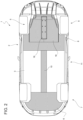
figure 2 is a schematic bottom view, with parts removed for greater clarity, of the car offigure 1 ; -
figure 3 is a schematic perspective view, with parts removed for greater clarity, of a detail of the car offigure 1 ; -
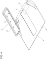
figure 4 is a schematic, exploded perspective view, with parts removed for greater clarity, of a detail offigure 3 ; -
figure 5 is a schematic perspective view, with sectional parts and with parts removed for greater clarity, of the detail offigure 3 ; and -
figure 6 is a schematic perspective view, with sectional parts and with parts removed for greater clarity, of a variant of the detail offigure 3 . - With reference to
figures 1 and2 , number 1 indicates, as a whole, a car, in particular a sports car, comprising asupport frame 2 defining part of alower floor 3 of the car 1. - The car 1 further comprises a
passenger compartment 4, which is mounted on theframe 2 and projects upwards from thefloor 3, and anaerodynamic bottom 5, which is partly fixed to theframe 2 and defines part of thefloor 3. - The
bottom 5 comprises afront bottom 6, which is fixed to theframe 2 in afront area 7 of the car 1, arear bottom 8, which is mounted in arear area 9 of the car 1, and an elongatedcentral bottom 10, which is fixed to theframe 2 between thebottoms central area 11 of the car 1. - According to
figures 3 ,4 and5 , the car 1 further comprises adriving engine 12, which is mounted at the centre of therear area 9 and is connected to theframe 2 through the interposition of a known elastic shock absorber device, which is not shown herein, so as to have at least one degree of freedom relative to theframe 2 during the normal operation of the car 1. - The
engine 12 comprises acrankcase 13, acylinder head 14 facing thefloor 3 and atransmission shaft 15 and is oriented so that thecylinder head 14 is arranged under theshaft 15. - The
rear bottom 8 comprises afixed portion 16, which has an annular shape, is fixed to theframe 2 and is provided with acentral opening 17 with a substantially rectangular shape, and amovable portion 18, which has the shape of a substantially rectangular tank and is fixed under thecylinder head 14. - Since the
portion 18 is fixed to thecylinder head 14 and theengine 12 is connected to theframe 2 through the interposition of the aforesaid elastic shock absorber device (not shown), the assembly defined by theengine 12 and by theportion 18 is movable relative to theframe 2 during the normal operation of the car 1. - The
portion 18 is delimited by abottom wall 19, which is substantially coplanar to theportion 16, is fixed to thecylinder head 14 and is provided with an outerperipheral edge 20. - The
edge 20 projects upwards from thewall 19, is bent on top of and along an innerperipheral edge 21 of theopening 17 and is arranged at a distance from theedge 21 so as to allow air to flow along thefloor 3 and prevent air from penetrating between theedges - The variant shown in
figure 6 differs fromfigures 3 and5 only in that, in it, themovable portion 18 is eliminated and replaced by amovable portion 22, which has the shape of a substantially rectangular plate, extends inside theopening 17 and is substantially coplanar to theportion 16. - The
portion 22 has an outerperipheral edge 23 connected to theedge 21 through the interposition of anannular gasket 24, which is made of an elastically deformable material and is coupled, on one side, to theedge 21 and, on the other side, to theedge 23. - The configuration of the
rear bottom 8, namely the presence of thefixed portion 16 and of themovable portion driving engine 12 and the centre of gravity of the car 1 to be lowered and, hence, ensures relatively high aerodynamics of the car 1. - The configuration of the outer
peripheral edge 20 of themovable portion 18 and of the innerperipheral edge 21 of theopening 17 and the presence of theannular gasket 24 allow thefixed portion 16 and themovable portion rear bottom 8 to be correctly joined to one another and, hence, ensure relatively high aerodynamics of the car 1.
Claims (9)
- A car comprising a support frame (2) defining part of a lower floor (3) of the car; a passenger compartment (4) projecting upwards from the lower floor (3); a driving engine (12) to move the car; and an aerodynamic bottom (5) at least partly fixed to the support frame (2) and defining part of the lower floor (3); and characterized in that the aerodynamic bottom (5) comprises a fixed portion (16) locked on the support frame (2) and a movable portion (18; 22) locked on the driving engine (12) and movable relative to the fixed portion (16).
- The car according to claim 1, wherein the driving engine (12) is mounted on the support frame (2) through the interposition of an elastic shock absorber device.
- The car according to claim 1 or 2, wherein the fixed portion (16) has an annular shape and extends around the movable portion (18; 22).
- The car according to claim 3, wherein the fixed portion (16) has an inner peripheral edge (21) and the movable portion (18; 22) has an outer peripheral edge (20; 23) .
- The car according to claim 4, wherein the outer peripheral edge (20) of the movable portion (18) is bent upwards from a bottom wall (19) of the movable portion (18) and extends above and around the inner peripheral edge (21) of the fixed portion (16).
- The car according to claim 4, wherein the aerodynamic bottom (5) further comprises an annular gasket (24), which is elastically deformable and is interposed between the outer peripheral edge (23) of the movable portion (22) and the inner peripheral edge (21) of the fixed portion (16) .
- The car according to any one of the preceding claims, wherein the driving engine (12) is mounted at the centre of a rear zone (9) of the car.
- The car according to claim 7, wherein the fixed portion (16) and the movable portion (18; 22) of the aerodynamic bottom (5) are mounted in the area of the rear zone (9) of the car.
- The car according to any one of the preceding claims, wherein the driving engine (12) comprises a cylinder head (14), a crankcase (13) and a drive shaft (15) extending above the cylinder head (14); the movable portion (18; 22) of the aerodynamic bottom (5) being fixed to the cylinder head (14) of the driving engine (12).
Applications Claiming Priority (1)
| Application Number | Priority Date | Filing Date | Title |
|---|---|---|---|
| IT102022000018468A IT202200018468A1 (en) | 2022-09-12 | 2022-09-12 | CAR |
Publications (1)
| Publication Number | Publication Date |
|---|---|
| EP4339079A1 true EP4339079A1 (en) | 2024-03-20 |
Family
ID=84331087
Family Applications (1)
| Application Number | Title | Priority Date | Filing Date |
|---|---|---|---|
| EP23196213.5A Pending EP4339079A1 (en) | 2022-09-12 | 2023-09-08 | Car |
Country Status (5)
| Country | Link |
|---|---|
| US (1) | US20240083522A1 (en) |
| EP (1) | EP4339079A1 (en) |
| JP (1) | JP2024040127A (en) |
| CN (1) | CN117681975A (en) |
| IT (1) | IT202200018468A1 (en) |
Families Citing this family (1)
| Publication number | Priority date | Publication date | Assignee | Title |
|---|---|---|---|---|
| CN119099734A (en) * | 2023-06-07 | 2024-12-10 | 本田技研工业株式会社 | Vehicle bottom structure |
Citations (3)
| Publication number | Priority date | Publication date | Assignee | Title |
|---|---|---|---|---|
| US20130181476A1 (en) * | 2010-09-30 | 2013-07-18 | Honda Motor Co., Ltd. | Car body forepart structure |
| US20170174272A1 (en) * | 2014-09-04 | 2017-06-22 | Honda Motor Co., Ltd. | Vehicle understructure |
| US20200102020A1 (en) * | 2018-09-27 | 2020-04-02 | Honda Motor Co., Ltd. | Vehicle body lower structure |
Family Cites Families (5)
| Publication number | Priority date | Publication date | Assignee | Title |
|---|---|---|---|---|
| US6875258B2 (en) * | 2003-04-09 | 2005-04-05 | Ti Group Automotive Systems, L.L.C. | Fuel tank assembly |
| DE10346319A1 (en) * | 2003-10-06 | 2005-04-28 | Anton Strahm | Hinged engine and transmission mounting for road vehicle has hinge midway between front and rear wheels allowing sub-frame with engine, gearbox and rear wheels to be swung down for access for maintenance |
| CN110356490A (en) * | 2018-04-10 | 2019-10-22 | 北极星工业有限公司 | Multi-purpose vehicle |
| US10889173B2 (en) * | 2018-09-19 | 2021-01-12 | Textron Inc. | Powertrain |
| US10800353B2 (en) * | 2018-10-24 | 2020-10-13 | Deere & Company | Utility vehicle powertrain enclosure |
-
2022
- 2022-09-12 IT IT102022000018468A patent/IT202200018468A1/en unknown
-
2023
- 2023-09-07 US US18/462,924 patent/US20240083522A1/en active Pending
- 2023-09-08 JP JP2023145801A patent/JP2024040127A/en active Pending
- 2023-09-08 EP EP23196213.5A patent/EP4339079A1/en active Pending
- 2023-09-11 CN CN202311170594.6A patent/CN117681975A/en active Pending
Patent Citations (3)
| Publication number | Priority date | Publication date | Assignee | Title |
|---|---|---|---|---|
| US20130181476A1 (en) * | 2010-09-30 | 2013-07-18 | Honda Motor Co., Ltd. | Car body forepart structure |
| US20170174272A1 (en) * | 2014-09-04 | 2017-06-22 | Honda Motor Co., Ltd. | Vehicle understructure |
| US20200102020A1 (en) * | 2018-09-27 | 2020-04-02 | Honda Motor Co., Ltd. | Vehicle body lower structure |
Also Published As
| Publication number | Publication date |
|---|---|
| IT202200018468A1 (en) | 2024-03-12 |
| CN117681975A (en) | 2024-03-12 |
| JP2024040127A (en) | 2024-03-25 |
| US20240083522A1 (en) | 2024-03-14 |
Similar Documents
| Publication | Publication Date | Title |
|---|---|---|
| US7117926B2 (en) | Heat exchanger support structure of motor vehicle | |
| EP4339079A1 (en) | Car | |
| ES2370302T3 (en) | TECHNICAL FRONT SIDE OF AN AUTOMOBILE VEHICLE, TECHNICAL FRONT AND REFRIGERATION MODULE SUPPORT EQUIPPED WITH A SLEEVE OF THIS TYPE. | |
| EP4342773A1 (en) | Car | |
| US20080073479A1 (en) | Engine bracket | |
| US9963027B2 (en) | Windshield glass peripheral structure | |
| WO2018169552A1 (en) | Vehicle bumper assembly | |
| CN105313983B (en) | The front-body structure of vehicle | |
| JP2005297888A (en) | Auto body front structure | |
| US20170158163A1 (en) | Vehicle hood | |
| US20240294216A1 (en) | Car provided with a pneumatic unit operated by a gearbox | |
| US6435299B1 (en) | Propeller shaft deflector | |
| US20080047769A1 (en) | Engine transmission carrier | |
| US20180222419A1 (en) | Bumper assemblies and vehicles with integrated air deflectors | |
| US20080018137A1 (en) | Assembly comprising a headlamp block support and a motor vehicle fender, and a support forming part of such an assembly | |
| US9975579B2 (en) | Cowl structure | |
| US12202408B2 (en) | Vehicle door assembly | |
| JP2005280628A (en) | Cowl top cover | |
| US11541946B2 (en) | Transmission mount of rear wheel drive vehicle | |
| CN210531481U (en) | Shock absorber installing support and shock absorber assembly | |
| US8870268B2 (en) | Motor vehicle body | |
| US10363967B2 (en) | Front side member | |
| JP4961764B2 (en) | Automotive engine hood structure | |
| US20240198787A1 (en) | Air cooling means for cooling motor vehicle components | |
| CN223212185U (en) | Beam suspension assembly and vehicle |
Legal Events
| Date | Code | Title | Description |
|---|---|---|---|
| PUAI | Public reference made under article 153(3) epc to a published international application that has entered the european phase |
Free format text: ORIGINAL CODE: 0009012 |
|
| STAA | Information on the status of an ep patent application or granted ep patent |
Free format text: STATUS: THE APPLICATION HAS BEEN PUBLISHED |
|
| AK | Designated contracting states |
Kind code of ref document: A1 Designated state(s): AL AT BE BG CH CY CZ DE DK EE ES FI FR GB GR HR HU IE IS IT LI LT LU LV MC ME MK MT NL NO PL PT RO RS SE SI SK SM TR |
|
| STAA | Information on the status of an ep patent application or granted ep patent |
Free format text: STATUS: REQUEST FOR EXAMINATION WAS MADE |
|
| 17P | Request for examination filed |
Effective date: 20240329 |
|
| RBV | Designated contracting states (corrected) |
Designated state(s): AL AT BE BG CH CY CZ DE DK EE ES FI FR GB GR HR HU IE IS IT LI LT LU LV MC ME MK MT NL NO PL PT RO RS SE SI SK SM TR |
|
| STAA | Information on the status of an ep patent application or granted ep patent |
Free format text: STATUS: EXAMINATION IS IN PROGRESS |
|
| 17Q | First examination report despatched |
Effective date: 20240903 |