EP4339070A1 - Operation assistance system and operation assistance method - Google Patents
Operation assistance system and operation assistance method Download PDFInfo
- Publication number
- EP4339070A1 EP4339070A1 EP22807371.4A EP22807371A EP4339070A1 EP 4339070 A1 EP4339070 A1 EP 4339070A1 EP 22807371 A EP22807371 A EP 22807371A EP 4339070 A1 EP4339070 A1 EP 4339070A1
- Authority
- EP
- European Patent Office
- Prior art keywords
- train
- deceleration
- traveling
- information
- power
- Prior art date
- Legal status (The legal status is an assumption and is not a legal conclusion. Google has not performed a legal analysis and makes no representation as to the accuracy of the status listed.)
- Pending
Links
Images


Classifications
-
- B—PERFORMING OPERATIONS; TRANSPORTING
- B61—RAILWAYS
- B61L—GUIDING RAILWAY TRAFFIC; ENSURING THE SAFETY OF RAILWAY TRAFFIC
- B61L27/00—Central railway traffic control systems; Trackside control; Communication systems specially adapted therefor
- B61L27/10—Operations, e.g. scheduling or time tables
- B61L27/16—Trackside optimisation of vehicle or train operation
-
- B—PERFORMING OPERATIONS; TRANSPORTING
- B60—VEHICLES IN GENERAL
- B60L—PROPULSION OF ELECTRICALLY-PROPELLED VEHICLES; SUPPLYING ELECTRIC POWER FOR AUXILIARY EQUIPMENT OF ELECTRICALLY-PROPELLED VEHICLES; ELECTRODYNAMIC BRAKE SYSTEMS FOR VEHICLES IN GENERAL; MAGNETIC SUSPENSION OR LEVITATION FOR VEHICLES; MONITORING OPERATING VARIABLES OF ELECTRICALLY-PROPELLED VEHICLES; ELECTRIC SAFETY DEVICES FOR ELECTRICALLY-PROPELLED VEHICLES
- B60L15/00—Methods, circuits, or devices for controlling the traction-motor speed of electrically-propelled vehicles
- B60L15/20—Methods, circuits, or devices for controlling the traction-motor speed of electrically-propelled vehicles for control of the vehicle or its driving motor to achieve a desired performance, e.g. speed, torque, programmed variation of speed
- B60L15/2009—Methods, circuits, or devices for controlling the traction-motor speed of electrically-propelled vehicles for control of the vehicle or its driving motor to achieve a desired performance, e.g. speed, torque, programmed variation of speed for braking
-
- B—PERFORMING OPERATIONS; TRANSPORTING
- B60—VEHICLES IN GENERAL
- B60L—PROPULSION OF ELECTRICALLY-PROPELLED VEHICLES; SUPPLYING ELECTRIC POWER FOR AUXILIARY EQUIPMENT OF ELECTRICALLY-PROPELLED VEHICLES; ELECTRODYNAMIC BRAKE SYSTEMS FOR VEHICLES IN GENERAL; MAGNETIC SUSPENSION OR LEVITATION FOR VEHICLES; MONITORING OPERATING VARIABLES OF ELECTRICALLY-PROPELLED VEHICLES; ELECTRIC SAFETY DEVICES FOR ELECTRICALLY-PROPELLED VEHICLES
- B60L15/00—Methods, circuits, or devices for controlling the traction-motor speed of electrically-propelled vehicles
- B60L15/20—Methods, circuits, or devices for controlling the traction-motor speed of electrically-propelled vehicles for control of the vehicle or its driving motor to achieve a desired performance, e.g. speed, torque, programmed variation of speed
- B60L15/2045—Methods, circuits, or devices for controlling the traction-motor speed of electrically-propelled vehicles for control of the vehicle or its driving motor to achieve a desired performance, e.g. speed, torque, programmed variation of speed for optimising the use of energy
-
- B—PERFORMING OPERATIONS; TRANSPORTING
- B60—VEHICLES IN GENERAL
- B60L—PROPULSION OF ELECTRICALLY-PROPELLED VEHICLES; SUPPLYING ELECTRIC POWER FOR AUXILIARY EQUIPMENT OF ELECTRICALLY-PROPELLED VEHICLES; ELECTRODYNAMIC BRAKE SYSTEMS FOR VEHICLES IN GENERAL; MAGNETIC SUSPENSION OR LEVITATION FOR VEHICLES; MONITORING OPERATING VARIABLES OF ELECTRICALLY-PROPELLED VEHICLES; ELECTRIC SAFETY DEVICES FOR ELECTRICALLY-PROPELLED VEHICLES
- B60L15/00—Methods, circuits, or devices for controlling the traction-motor speed of electrically-propelled vehicles
- B60L15/40—Adaptation of control equipment on vehicle for remote actuation from a stationary place
-
- B—PERFORMING OPERATIONS; TRANSPORTING
- B60—VEHICLES IN GENERAL
- B60L—PROPULSION OF ELECTRICALLY-PROPELLED VEHICLES; SUPPLYING ELECTRIC POWER FOR AUXILIARY EQUIPMENT OF ELECTRICALLY-PROPELLED VEHICLES; ELECTRODYNAMIC BRAKE SYSTEMS FOR VEHICLES IN GENERAL; MAGNETIC SUSPENSION OR LEVITATION FOR VEHICLES; MONITORING OPERATING VARIABLES OF ELECTRICALLY-PROPELLED VEHICLES; ELECTRIC SAFETY DEVICES FOR ELECTRICALLY-PROPELLED VEHICLES
- B60L7/00—Electrodynamic brake systems for vehicles in general
- B60L7/10—Dynamic electric regenerative braking
-
- B—PERFORMING OPERATIONS; TRANSPORTING
- B60—VEHICLES IN GENERAL
- B60M—POWER SUPPLY LINES, AND DEVICES ALONG RAILS, FOR ELECTRICALLY- PROPELLED VEHICLES
- B60M3/00—Feeding power to supply lines in contact with collector on vehicles; Arrangements for consuming regenerative power
- B60M3/06—Arrangements for consuming regenerative power
-
- B—PERFORMING OPERATIONS; TRANSPORTING
- B61—RAILWAYS
- B61L—GUIDING RAILWAY TRAFFIC; ENSURING THE SAFETY OF RAILWAY TRAFFIC
- B61L27/00—Central railway traffic control systems; Trackside control; Communication systems specially adapted therefor
- B61L27/20—Trackside control of safe travel of vehicle or train, e.g. braking curve calculation
-
- B—PERFORMING OPERATIONS; TRANSPORTING
- B61—RAILWAYS
- B61L—GUIDING RAILWAY TRAFFIC; ENSURING THE SAFETY OF RAILWAY TRAFFIC
- B61L27/00—Central railway traffic control systems; Trackside control; Communication systems specially adapted therefor
- B61L27/40—Handling position reports or trackside vehicle data
-
- B—PERFORMING OPERATIONS; TRANSPORTING
- B60—VEHICLES IN GENERAL
- B60L—PROPULSION OF ELECTRICALLY-PROPELLED VEHICLES; SUPPLYING ELECTRIC POWER FOR AUXILIARY EQUIPMENT OF ELECTRICALLY-PROPELLED VEHICLES; ELECTRODYNAMIC BRAKE SYSTEMS FOR VEHICLES IN GENERAL; MAGNETIC SUSPENSION OR LEVITATION FOR VEHICLES; MONITORING OPERATING VARIABLES OF ELECTRICALLY-PROPELLED VEHICLES; ELECTRIC SAFETY DEVICES FOR ELECTRICALLY-PROPELLED VEHICLES
- B60L2200/00—Type of vehicles
- B60L2200/26—Rail vehicles
-
- B—PERFORMING OPERATIONS; TRANSPORTING
- B60—VEHICLES IN GENERAL
- B60L—PROPULSION OF ELECTRICALLY-PROPELLED VEHICLES; SUPPLYING ELECTRIC POWER FOR AUXILIARY EQUIPMENT OF ELECTRICALLY-PROPELLED VEHICLES; ELECTRODYNAMIC BRAKE SYSTEMS FOR VEHICLES IN GENERAL; MAGNETIC SUSPENSION OR LEVITATION FOR VEHICLES; MONITORING OPERATING VARIABLES OF ELECTRICALLY-PROPELLED VEHICLES; ELECTRIC SAFETY DEVICES FOR ELECTRICALLY-PROPELLED VEHICLES
- B60L2240/00—Control parameters of input or output; Target parameters
- B60L2240/10—Vehicle control parameters
- B60L2240/12—Speed
-
- B—PERFORMING OPERATIONS; TRANSPORTING
- B60—VEHICLES IN GENERAL
- B60L—PROPULSION OF ELECTRICALLY-PROPELLED VEHICLES; SUPPLYING ELECTRIC POWER FOR AUXILIARY EQUIPMENT OF ELECTRICALLY-PROPELLED VEHICLES; ELECTRODYNAMIC BRAKE SYSTEMS FOR VEHICLES IN GENERAL; MAGNETIC SUSPENSION OR LEVITATION FOR VEHICLES; MONITORING OPERATING VARIABLES OF ELECTRICALLY-PROPELLED VEHICLES; ELECTRIC SAFETY DEVICES FOR ELECTRICALLY-PROPELLED VEHICLES
- B60L2240/00—Control parameters of input or output; Target parameters
- B60L2240/60—Navigation input
- B60L2240/62—Vehicle position
-
- B—PERFORMING OPERATIONS; TRANSPORTING
- B60—VEHICLES IN GENERAL
- B60L—PROPULSION OF ELECTRICALLY-PROPELLED VEHICLES; SUPPLYING ELECTRIC POWER FOR AUXILIARY EQUIPMENT OF ELECTRICALLY-PROPELLED VEHICLES; ELECTRODYNAMIC BRAKE SYSTEMS FOR VEHICLES IN GENERAL; MAGNETIC SUSPENSION OR LEVITATION FOR VEHICLES; MONITORING OPERATING VARIABLES OF ELECTRICALLY-PROPELLED VEHICLES; ELECTRIC SAFETY DEVICES FOR ELECTRICALLY-PROPELLED VEHICLES
- B60L2240/00—Control parameters of input or output; Target parameters
- B60L2240/60—Navigation input
- B60L2240/68—Traffic data
-
- B—PERFORMING OPERATIONS; TRANSPORTING
- B60—VEHICLES IN GENERAL
- B60L—PROPULSION OF ELECTRICALLY-PROPELLED VEHICLES; SUPPLYING ELECTRIC POWER FOR AUXILIARY EQUIPMENT OF ELECTRICALLY-PROPELLED VEHICLES; ELECTRODYNAMIC BRAKE SYSTEMS FOR VEHICLES IN GENERAL; MAGNETIC SUSPENSION OR LEVITATION FOR VEHICLES; MONITORING OPERATING VARIABLES OF ELECTRICALLY-PROPELLED VEHICLES; ELECTRIC SAFETY DEVICES FOR ELECTRICALLY-PROPELLED VEHICLES
- B60L2240/00—Control parameters of input or output; Target parameters
- B60L2240/70—Interactions with external data bases, e.g. traffic centres
-
- B—PERFORMING OPERATIONS; TRANSPORTING
- B60—VEHICLES IN GENERAL
- B60L—PROPULSION OF ELECTRICALLY-PROPELLED VEHICLES; SUPPLYING ELECTRIC POWER FOR AUXILIARY EQUIPMENT OF ELECTRICALLY-PROPELLED VEHICLES; ELECTRODYNAMIC BRAKE SYSTEMS FOR VEHICLES IN GENERAL; MAGNETIC SUSPENSION OR LEVITATION FOR VEHICLES; MONITORING OPERATING VARIABLES OF ELECTRICALLY-PROPELLED VEHICLES; ELECTRIC SAFETY DEVICES FOR ELECTRICALLY-PROPELLED VEHICLES
- B60L2240/00—Control parameters of input or output; Target parameters
- B60L2240/80—Time limits
-
- B—PERFORMING OPERATIONS; TRANSPORTING
- B60—VEHICLES IN GENERAL
- B60L—PROPULSION OF ELECTRICALLY-PROPELLED VEHICLES; SUPPLYING ELECTRIC POWER FOR AUXILIARY EQUIPMENT OF ELECTRICALLY-PROPELLED VEHICLES; ELECTRODYNAMIC BRAKE SYSTEMS FOR VEHICLES IN GENERAL; MAGNETIC SUSPENSION OR LEVITATION FOR VEHICLES; MONITORING OPERATING VARIABLES OF ELECTRICALLY-PROPELLED VEHICLES; ELECTRIC SAFETY DEVICES FOR ELECTRICALLY-PROPELLED VEHICLES
- B60L2260/00—Operating Modes
- B60L2260/20—Drive modes; Transition between modes
- B60L2260/22—Standstill, e.g. zero speed
-
- B—PERFORMING OPERATIONS; TRANSPORTING
- B60—VEHICLES IN GENERAL
- B60L—PROPULSION OF ELECTRICALLY-PROPELLED VEHICLES; SUPPLYING ELECTRIC POWER FOR AUXILIARY EQUIPMENT OF ELECTRICALLY-PROPELLED VEHICLES; ELECTRODYNAMIC BRAKE SYSTEMS FOR VEHICLES IN GENERAL; MAGNETIC SUSPENSION OR LEVITATION FOR VEHICLES; MONITORING OPERATING VARIABLES OF ELECTRICALLY-PROPELLED VEHICLES; ELECTRIC SAFETY DEVICES FOR ELECTRICALLY-PROPELLED VEHICLES
- B60L2260/00—Operating Modes
- B60L2260/40—Control modes
- B60L2260/50—Control modes by future state prediction
- B60L2260/54—Energy consumption estimation
-
- B—PERFORMING OPERATIONS; TRANSPORTING
- B60—VEHICLES IN GENERAL
- B60L—PROPULSION OF ELECTRICALLY-PROPELLED VEHICLES; SUPPLYING ELECTRIC POWER FOR AUXILIARY EQUIPMENT OF ELECTRICALLY-PROPELLED VEHICLES; ELECTRODYNAMIC BRAKE SYSTEMS FOR VEHICLES IN GENERAL; MAGNETIC SUSPENSION OR LEVITATION FOR VEHICLES; MONITORING OPERATING VARIABLES OF ELECTRICALLY-PROPELLED VEHICLES; ELECTRIC SAFETY DEVICES FOR ELECTRICALLY-PROPELLED VEHICLES
- B60L2260/00—Operating Modes
- B60L2260/40—Control modes
- B60L2260/50—Control modes by future state prediction
- B60L2260/58—Departure time prediction
-
- Y—GENERAL TAGGING OF NEW TECHNOLOGICAL DEVELOPMENTS; GENERAL TAGGING OF CROSS-SECTIONAL TECHNOLOGIES SPANNING OVER SEVERAL SECTIONS OF THE IPC; TECHNICAL SUBJECTS COVERED BY FORMER USPC CROSS-REFERENCE ART COLLECTIONS [XRACs] AND DIGESTS
- Y02—TECHNOLOGIES OR APPLICATIONS FOR MITIGATION OR ADAPTATION AGAINST CLIMATE CHANGE
- Y02T—CLIMATE CHANGE MITIGATION TECHNOLOGIES RELATED TO TRANSPORTATION
- Y02T90/00—Enabling technologies or technologies with a potential or indirect contribution to GHG emissions mitigation
- Y02T90/10—Technologies relating to charging of electric vehicles
- Y02T90/16—Information or communication technologies improving the operation of electric vehicles
Definitions
- the present invention relates to a driver assistance system and a driver assistance method for an electric railway.
- the regenerative brake is a deceleration means for securing a braking force by an electromotive force of a motor mounted on a train, and can be reused by converting kinetic energy of the train consumed as heat in the conventional friction brake into power.
- the power (regenerative power) generated by the regenerative brake is supplied as driving power for another train via an overhead line.
- the regenerative power cannot be used.
- a technique for controlling the operation of the train so as to drive another train according to the generation of the regenerative power is required.
- PTL 1 discloses a technique in which a regenerative braking operation start time of a traveling train is predicted, and a departure time of a train stopping at a station is made to wait until the predicted regenerative braking operation start time, so that a train departing from the station can use regenerative power.
- the station departure time of the train whose operation is controlled according to the regenerative train is delayed with respect to the operation schedule.
- the train after departure from the station needs to be driven at a higher speed than usual in order to eliminate the delay, and there is a problem that energy consumption is larger than that in normal driving.
- an object of the present invention is to provide a system and a method for assisting operation of a train in order to effectively use regenerative power generated by a traveling deceleration-side train as power for driving a power-running-side train without causing a delay in the power-running-side train departing from a station.
- one of the representative driver assistance systems of the present invention includes: a first on-board device mounted on at least one stopping train; a second on-board device mounted on at least one traveling train; and a ground-side device that communicates information with the first on-board device and the second on-board device via a transmission line, in which the ground-side device generates a deceleration pattern of the traveling train based on power running start information of the stopping train obtained from at least reception information from the first on-board device, and transmits the deceleration pattern to the second on-board device.
- the train driver assistance device capable of predicting the power running start time of the power-running-side train and reflecting the predicted power running start time in the adjustment of the regenerative brake start time of the regenerative-side train even when the travel of the train is delayed from a predetermined operation schedule, it is possible to efficiently use the regenerative power by the regenerative brake of the train and reduce the energy consumption related to the train operation.
- a determined power running start time is obtained using information (hereinafter, referred to as "power running notch input information") to which a power running notch is input, a traveling pattern in which deceleration starts from the power running start time is generated, and train operation control is performed according to the generated traveling pattern.
- FIG. 1 is a diagram illustrating a configuration of a driver assistance system according to the first embodiment of the present invention and a train to be a driver assistance target.
- the configuration of the driver assistance system is the same as that of a second embodiment described later.
- the driver assistance system includes an on-board device 104A mounted on a first train 101A, an on-board device 104B and a driving control device 106B mounted on a second train 101B, a ground-side device 103, and a transmission line 102 for mutually communicating information related to these devices.
- an on-board device mounted on the train may be configured to include the same mounted driving control device.
- the ground-side device 103 includes at least a calculation unit 107 and a schedule database 108 that stores each station departure time for each train.
- the first train 101A is stopped at a station 113, and transmits power running notch input information 111 from the on-board device 104A to the ground-side device 103 via the transmission line 102.
- the second train 101B is traveling, and transmits position information 109B and speed information 110B from the on-board device 104B to the ground-side device 103 via the transmission line 102.
- the calculation unit 107 uses the power running notch input information 111 received from the on-board device 104A of the first train 101A as a trigger for starting the power running of the train 101A, generates a target deceleration pattern 112 of the second train 101B using the schedule database 108 based on the position information 109B and the speed information 110B received from the second train 101B, and transmits the target deceleration pattern 112 to the second train 101B via the transmission line 102.
- the driving control device 106B controls the speed of the train so as to follow the target deceleration pattern 112 received from the ground-side device 103.
- the transmission line 102 includes a known wireless line such as a public wireless line such as a mobile phone, or a dedicated wireless line for a railway such as a train radio or a train signal device.
- a known wireless line such as a public wireless line such as a mobile phone, or a dedicated wireless line for a railway such as a train radio or a train signal device.
- a driving control device 106 (the driving control device 106B in the second train 101B) mounted on the train side includes an automatic train driving device that automatically follows a given target driving pattern or a train driver assistance system that can follow an driving pattern instructed to an operator by manual operation.
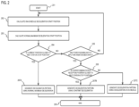
- FIG. 2 is a diagram illustrating a flow (flowchart) of processing executed by the calculation unit 107 included in the ground-side device 103 of the driver assistance system in the case of the first embodiment.
- the notation of the calculation unit 107 that is the execution subject of each process is omitted.
- a deceleration start position 302C (hereinafter, referred to as “on-schedule deceleration start position 302C") necessary for the second train (deceleration-side train) 101B to stop at the next station with the minimum deceleration (hereinafter, referred to as “deceleration on schedule”) necessary for stopping at the stop position of the next station at the next station arrival time on the schedule from the current speed 110B is calculated. Thereafter, the processing proceeds to a process 203.
- a normal maximum deceleration start position 302A necessary for the second train (deceleration-side train) 101B to stop at the next station at the normal maximum deceleration at the next station arrival time on the schedule from the current speed 110B is calculated. Thereafter, the process proceeds to a conditional branch 204.
- the current position 109B of the second train (deceleration-side train) 101B is compared with the normal maximum deceleration start position 302A, and it is determined whether or not the current position 109B is closer to a next station stop position 301 than the normal maximum deceleration start position 302A.
- conditional branch 205 it is determined whether the power running notch input information 111 has been input.
- the processing proceeds to the conditional branch 206, and if not confirmed (NO), the process returns to the process 202.
- the position 302B (hereinafter, referred to as "power running notch reception position 302B") at which the power running notch input information 111 has been received is compared with the on-schedule deceleration start position 302C, and it is determined whether or not the power running notch reception position 302B is closer to the next station stop position 301 than the on-schedule deceleration start position 302C. As a result of the determination, if it is close (YES), the processing proceeds to a process 207B, and otherwise (NO), the processing proceeds to a process 207C.
- a deceleration pattern 303A in which the second train (deceleration-side train) 101B stops at the next station at the normal maximum deceleration is generated and set as the target deceleration pattern 112.
- a deceleration pattern 303B in which the second train (deceleration-side train) 101B starts deceleration from the power running notch reception position 302B and stops at the next station at a constant deceleration ⁇ is generated and set as the target deceleration pattern 112.
- time: t, speed: v, position: x are variables, speed 110B: v 0 , distance from the power running notch reception position 302B to the next station stop position 301: ⁇ x, remaining time until the next station stop time on the schedule: ⁇ t
- a deceleration pattern 303C in which the second train (deceleration-side train) 101B stops at the next station at the deceleration on the schedule is generated and set as the target deceleration pattern 112.
- FIG. 3 is a diagram illustrating a driving curve of the second train (deceleration-side train) 101B according to the flowchart illustrated in FIG. 2 .
- the calculation unit 107 When the power running notch input information 111 is not received until the normal maximum deceleration start position 302A, the calculation unit 107 generates the deceleration pattern 303A in which the second train (deceleration-side train) 101B starts deceleration from the normal maximum deceleration start position 302A and the speed becomes 0 at the next station stop position 301.
- the driving control device 106B controls the speed of the second train (deceleration-side train) 101B to follow the target deceleration pattern 112 (deceleration pattern 303A) received from the calculation unit 107, so that the second train (deceleration-side train) 101B travels like a travel history 304A.
- the calculation unit 107 When the train is closer to the next station than the on-schedule deceleration start position 302C and the power running notch input information 111 is received, the calculation unit 107 generates the deceleration pattern 303B in which the second train (deceleration-side train) 101B starts to decelerate from the power running notch reception position 302B and the speed becomes 0 at the next station stop position 301.
- the driving control device 106B controls the speed of the second train (deceleration-side train) 101B to follow the target deceleration pattern 112 (deceleration pattern 303B) received from the calculation unit 107, so that the second train (deceleration-side train) 101B travels like a travel history 304B.
- the calculation unit 107 When the power running notch input information 111 is received before the on-schedule deceleration start position 302C, the calculation unit 107 generates the deceleration pattern 303C in which the second train (deceleration-side train) 101B starts deceleration from the on-schedule deceleration start position 302C and the speed becomes 0 at the next station stop position 301.
- the driving control device 106B controls the speed of the second train (deceleration-side train) 101B to follow the target deceleration pattern 112 (deceleration pattern 303C) received from the calculation unit 107, so that the second train (deceleration-side train) 101B travels like a travel history 304C.
- the deceleration may be continued at the deceleration as it is, or a more energy-saving pattern may be recalculated according to the on-track position and speed.
- the second train (deceleration-side train) 101B can start deceleration in accordance with the target deceleration pattern 112 corresponding to the input time of the power running notch and stop at the next station stop position 301.
- FIG. 4 is a diagram illustrating an effect of the driver assistance system according to the first embodiment.
- a waveform (dotted line) of power running power 401 by the first train (power-running-side train) 101A and waveforms (402A and 402B) of regenerative power 402 by the second train (deceleration-side train) 101B are illustrated, and the overlapped portion is the regenerative power that can be used by the first train (power-running-side train) 101A.
- the regenerative power 402A (alternate long and short dash line) is a case where there is no control by the driver assistance system
- the regenerative power 402B (solid line) is a case where control by the driver assistance system works.
- the regenerative power 402A (alternate long and short dash line) rises faster than the power running power 401, a large portion does not overlap the power running power 401.
- the regenerative power 402B (solid line) rises at the same time as the power running power 401 by the reception of the power running notch input information 111, so that the portion overlapping the power running power 401 increases.
- the deceleration of the traveling train is started in accordance with the departure of the train stopping at the station, so that the regenerative power can be effectively used as the driving power of the train departing from the station.
- a deceleration pattern generated by a driver assistance system according to the second embodiment is different from the deceleration pattern generated by the driver assistance system according to the first embodiment in that an effect of avoiding early arrival of the deceleration-side train can be obtained.
- the configuration of the driver assistance system according to the second embodiment is the same as the configuration of the driver assistance system according to the first embodiment.
- FIG. 5 is a diagram illustrating a flow (flowchart) of processing executed by a calculation unit 107 included in a ground-side device 103 of the driver assistance system in the case of the second embodiment.
- the second embodiment is different from the first embodiment in that a process 501, a process 502, and a process 503 are executed instead of the process 207B in the flowchart of the first embodiment.
- the execution subject of these processes is also the calculation unit 107, the description thereof will be omitted below.
- a first deceleration pattern 602A for decelerating at a first deceleration ⁇ 1 from a speed 110B is generated at a current position 109B of a second train (deceleration-side train) 101B.
- a second deceleration pattern 602B in which the second train (deceleration-side train) 101B stops at a next station stop position 301 at a next station stop time on a schedule at a second deceleration ⁇ 2 ( ⁇ 1 > ⁇ 2) different from the first deceleration ⁇ 1 is generated.
- a position 601 (hereinafter, referred to as "deceleration change point 601") at which the first deceleration pattern 602A and the second deceleration pattern 602B intersect is derived. That is, a deceleration pattern 603 in which the first deceleration pattern 602A is switched to the second deceleration pattern 602B at the deceleration change point 601, the first deceleration pattern 602A is set before the deceleration change point 601, and the second deceleration pattern 602B is set on the next station stop position 301 side from the deceleration change point 601 is generated as a target deceleration pattern 112.
- the second train (deceleration-side train) 101B can decelerate from the power running notch reception position 302B and stop at the next station stop position 301 at the next station arrival time on the schedule.
- time: t, speed: v, position: x are variables, speed 110B: v 0 , remaining time until the next station stop time on the schedule: ⁇ t, distance from the deceleration change point 601 to the next station stop position 301: ⁇ x, and time until switching from the first deceleration ⁇ 1 to the second deceleration ⁇ 2: t1.
- FIG. 6 is a diagram illustrating a driving curve of the second train (deceleration-side train) 101B according to the flowchart illustrated in FIG. 5 .
- the traveling characteristics of the second train (deceleration-side train) 101B when power running notch input information 111 is not received or when the power running notch input information 111 is received before an on-schedule deceleration start position 302C (position far from the next station stop position 301) are the same as those in the first embodiment, and thus are omitted.
- the calculation unit 107 When the power running notch input information 111 is received at a position farther from the on-schedule deceleration start position 302C (position closer to the next station stop position 301), the calculation unit 107 generates, as the target deceleration pattern 112, the deceleration pattern 603 that matches a deceleration pattern 602A of the deceleration ⁇ 1 on the near side (position farther from the next station stop position 301) and a deceleration pattern 602B that decelerates at the deceleration ⁇ 2 on the far side (position closer to the next station stop position 301) with the deceleration change point 601 as a boundary.
- a driving control device 106B controls the speed to follow the deceleration pattern 603 as the target deceleration pattern 112, so that the second train (deceleration-side train) 101B travels as in a travel history 604.
- the second train (deceleration-side train) 101B stops at the next station stop position 301 at the stop time on the schedule, so that it is possible to avoid early arrival. That is, as compared with the arrival time at the next station stop position 301 (the diagram of the lower time characteristics in FIG. 3 ) according to a travel history 304B in the case of a deceleration pattern 303B in the first embodiment, the arrival time at the next station stop position 301 (the diagram of the lower time characteristics in FIG.
- the travel history 604 in the case of the deceleration pattern 603 in the second embodiment indicates that the train arrives at the same time as the arrival time (stop time on the schedule) according to a deceleration pattern 303C from the on-schedule deceleration start position 302C without arriving early.
- FIG. 7 is a diagram illustrating an effect of the driver assistance system according to the second embodiment.
- Regenerative power 701 (thick solid line) according to the second embodiment when the power running notch input information 111 is received farther from the on-schedule deceleration start position 302C (position closer to the next station stop position 301) increases the time during which the regenerative power is generated as compared with the regenerative power 402B (thin solid line) according to the first embodiment in the same case. Therefore, the driver assistance system according to the second embodiment can effectively use the regenerative power as compared with the driver assistance system according to the first embodiment.
- the characteristics of a driver assistance system according to a third embodiment are different from those of the first and second embodiments in that a deceleration pattern for more effectively using regenerative power while avoiding early arrival of a deceleration-side train is generated by adjusting the speed of the deceleration-side train.
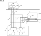
- FIG. 8 is a diagram illustrating a configuration of a driver assistance system according to the third embodiment of the present invention and a train to be a driver assistance target.
- the driver assistance system according to the third embodiment is different from the driver assistance systems according to the first and second embodiments in the following points.
- a ground-side device 103 newly includes a power running time prediction unit 802.
- the power running time prediction unit 802 uses a boarding rate 803 of a first train (power-running-side train) 101A and a congestion rate 804 of a station 113 as inputs, and calculates a power running start time 801 with reference to a congestion rate database 805 in response to these inputs.
- the congestion rate 804 on the platform of the station 113 is high, or when the boarding rate 803 of the first train (power-running-side train) 101A is high, the power running start time 801 is delayed from the power running start time on the schedule because a dwell time of passengers is longer than usual.
- a method of measuring the congestion rate 804 for example, a method of measuring from a captured image of a camera 806 installed on the platform of the station 113 is adopted.
- a method of measuring the boarding rate 803 for example, a method of measuring from the vehicle load of the first train (power-running-side train) 101A is adopted.
- a method is used in which the dwell time of passengers corresponding to the congestion rate of the station and the boarding rate of the train is accumulated in the congestion rate database 805, and the dwell time of the corresponding train is estimated from the measured congestion rate 804 and boarding rate 803.
- a calculation unit 107 receives the power running start time 801 calculated by the power running time prediction unit 802.
- FIG. 9 is a diagram illustrating a flow (flowchart) of processing executed by the calculation unit 107 and the power running time prediction unit 802 included in the ground-side device 103 of the driver assistance system in the case of the third embodiment.
- the power running time prediction unit 802 predicts the power running start time 801 with respect to the schedule time of the first train (power-running-side train) 101A from the congestion rate 804 on the platform of the station 113 and the boarding rate 803 of the train 101A. Thereafter, the processing proceeds to a process 92A.
- the calculation unit 107 calculates, for the second train (deceleration-side train) 101B, a deceleration start position (on-schedule deceleration start position 302C) necessary for stopping at the next station at the next station stop time on the schedule at the deceleration on the schedule and the time at the deceleration start (on-schedule deceleration start time 1002C), and the processing proceeds to a process 92B.
- a deceleration start position on-schedule deceleration start position 302C
- the calculation unit 107 calculates a normal maximum deceleration start time 1002A and a normal maximum deceleration start position 1001A when the train stops at the next station at the arrival time on the schedule using the normal maximum deceleration for the second train (deceleration-side train) 101B, and the processing proceeds to a conditional branch 93A.
- the calculation unit 107 compares the power running start time 801 with the normal maximum deceleration start time 1002A, and if the power running start time 801 is later than the normal maximum deceleration start time 1002A (YES), the processing proceeds to a process 95A, and otherwise (NO), the processing proceeds to a branch 94B.
- the calculation unit 107 compares the power running start time 801 with the on-schedule deceleration start time 1002C, and if the power running start time 801 is later than the on-schedule deceleration start time 1002C (YES), the processing proceeds to a process 95B, and otherwise (NO), the processing proceeds to a process 95C.
- the calculation unit 107 generates, for the second train (deceleration-side train) 101B, a deceleration pattern 1003A for stopping at the next station stop position 301 at the normal maximum deceleration, and sets the deceleration pattern 1003A as the target deceleration pattern 112.
- the calculation unit 107 generates, for the second train (deceleration-side train) 101B, a deceleration pattern 1003B that starts deceleration from the power running start time 801 and stops at the next station at a constant deceleration ⁇ , and sets the deceleration pattern 1003B as the target deceleration pattern 112.
- the calculation unit 107 generates a deceleration pattern 303C for the second train (deceleration-side train) 101B to stop at the next station at the deceleration on the schedule, and sets the deceleration pattern 303C as the target deceleration pattern 112.
- time: t, speed: v, position: x are variables, remaining time: ⁇ t, remaining distance: ⁇ x, and time until the power running start: t1.
- v t ⁇ v 0 , t ⁇ t 1 v 0 ⁇ ⁇ 2 t ⁇ t 1 , t ⁇ t 1
- x t ⁇ v t dt
- v ⁇ t 0
- FIG. 10 is a diagram illustrating a driving curve of the second train (deceleration-side train) 101B according to the flowchart illustrated in FIG. 9 .
- the calculation unit 107 When the power running start time 801 is earlier than the on-schedule deceleration start time (the time at which the train reaches the on-schedule deceleration start position 302C), the calculation unit 107 generates the deceleration pattern 303C in which deceleration is started from the on-schedule deceleration start position 302C and the speed becomes 0 at the next station stop position 301.
- a driving control device 106B controls the speed of the second train (deceleration-side train) 101B to follow the target deceleration pattern 112 (deceleration pattern 303C) received from the calculation unit 107, so that the second train (deceleration-side train) 101B travels like a travel history 304C.
- the driving control device 106B controls the speed of the second train (deceleration-side train) 101B to follow the target deceleration pattern 112 (deceleration pattern 1003B) received from the calculation unit 107, so that the second train (deceleration-side train) 101B travels like a travel history 1004B.
- the driving control device 106B controls the speed of the second train (deceleration-side train) 101B to follow the target deceleration pattern 112 (deceleration pattern 1003A) received from the calculation unit 107, so that the second train (deceleration-side train) 101B travels like a travel history 1004A.
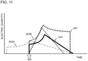
- FIG. 11 is a diagram illustrating an effect of the driver assistance system according to the third embodiment.
- the speed at the start of deceleration entering the deceleration pattern differs as illustrated in FIG. 10 according to the predicted power running start time 801. Therefore, the speed at the start of deceleration can be suppressed, whereby the deceleration can be controlled to be weaker.
- regenerative power 1101 has a waveform in which the deceleration is gentle (deceleration is suppressed) as compared with the regenerative power 402B (thin solid line) in the case of the first embodiment, and the regenerative power interchange amount can be increased as compared with the regenerative power 402A (alternate long and short dash line) in the case where there is no control by the driver assistance system.
- the driver assistance system As described above, according to the driver assistance system according to the third embodiment, it is possible to effectively use the regenerative power as the driving power of the train departing from the station while avoiding early arrival of the deceleration-side train.
- the plurality of deceleration-side trains decelerate so as to be synchronized with the power-running-side train at the same time, so that it is assumed that the regenerative power generation amount exceeds the power running power consumption amount.
- the fourth embodiment is characterized in that a plurality of deceleration-side trains are compared and a deceleration-side train to be controlled is selected with respect to three conditions of the distance between the power-running-side and deceleration-side trains, the deceleration of the deceleration-side train, and the delay time of the deceleration-side train.
- the fourth embodiment is different from the third embodiment in this point.
- FIG. 12 is a diagram illustrating a configuration of a driver assistance system according to the fourth embodiment of the present invention and a train to be a driver assistance target.
- the system according to the fourth embodiment is different from the system according to the third embodiment in the following points.
- a third train 101C is added as a deceleration-side train.
- the third train 101C exists on the same feeder system as the first train 101A and the second train 101B, and transmits its own position information 109C and speed information 110C from a third on-board device 104C to a ground-side device 103 via a transmission line 102, similarly to the second train 101B which is a deceleration-side train.
- a calculation unit 107 of the ground-side device 103 generates a target deceleration pattern 112B of the second train (deceleration-side train) 101B and a target deceleration pattern 112C of the third train (deceleration-side train) 101C based on received train position information 109A, 109B, and 109C, speed information 110B and 110C, and a schedule database 108.
- FIG. 13 is a diagram illustrating a flow (flowchart) of processing executed by the calculation unit 107 and a power running time prediction unit 802 included in the ground-side device 103 of the driver assistance system in the case of the fourth embodiment.
- the fourth embodiment is different from the third embodiment in the following points.
- processing steps different from those of the third embodiment will be described, and the other steps are the same as those of the third embodiment and will be omitted.
- FIG. 13 for the sake of convenience of the size of the paper surface, the process 91A ( FIG. 9 ) of predicting the power running start time following the start 21A in the third embodiment is included in the process 92A.
- the power running start time prediction process 91A is similarly executed following the start 21A.
- a conditional branch 1301A is added, and it is determined whether or not the target deceleration patterns have been generated in all the deceleration-side trains. As a result of the determination, in a case where all have been generated (YES), the processing proceeds to a process 1302A, and in a case where all have not been generated (NO), the processing proceeds to a process 1303B.
- an objective function having the distance between the power-running-side and deceleration-side trains, the deceleration of the deceleration-side-train, and the delay time of the deceleration-side-train as variables is set for the target deceleration pattern of each deceleration-side-train (in the fourth embodiment, the second train 101B and the third train 101C), and the target deceleration pattern 112 is transmitted only to the deceleration-side-train having the smallest value of the objective function.
- a deceleration pattern according to the schedule is transmitted to the other deceleration-side trains. Thereafter, the processing ends.
- the deceleration-side train for which the target deceleration pattern 112 is to be generated is switched. Thereafter, the processing proceeds to a process 92A.
- the objective function is defined as a function including variables x, a, and t, and as a specific example, a function having a linear correspondence with each variable is adopted.
- variables x and a are multiplied by the following gains k.
- this objective function is applied to all the deceleration-side trains on the same feeder line, and the target deceleration pattern 112 is transmitted only to the train having the smallest value of this objective function.
- FIG. 14 is a diagram illustrating a case where only deceleration is used as a variable of an objective function for the effect of the driver assistance system according to the fourth embodiment.
- the upper diagram of FIG. 14 illustrates the characteristics of the power amount, and the lower diagram of FIG. 14 illustrates the characteristics of the speed.
- regenerative power 1401B (alternate long and short dash line) and 1401C (broken line) respectively indicate the regenerative power generation amounts of the second train (deceleration-side train) 101B and the third train (deceleration-side train) 101C when the control by the driver assistance system is not performed, that is, when the deceleration start time is not adjusted.
- regenerative power 1402B thin solid line
- 1402C thin two-dot chain line
- regenerative power 1402B and 1402C respectively indicate the regenerative power generation amounts of the second train (deceleration-side train) 101B and the third train (deceleration-side train) 101C when the deceleration start time is adjusted under the control of the driver assistance system.
- speeds 1403B and 1403C respectively indicate speeds of the second train (deceleration-side train) 101B and the third train (deceleration-side train) 101C when the deceleration start time is adjusted.
- the calculation unit 107 transmits the target deceleration pattern 112C to the third train (deceleration-side train) 101C and adjusts the deceleration start time.
- the train to be controlled is selected from the plurality of deceleration-side trains by the objective function having the deceleration as a variable, whereby the regenerative power interchange can be performed while suppressing the deterioration of the ride comfort.
- a train to be controlled is selected by comprehensive determination of the plurality of variables.
- the fourth embodiment is an example in which the regenerative power is supplied to one power-running-side train from among the regenerative power of the plurality of deceleration-side trains, but the fifth embodiment is an example corresponding to a case where there are also a plurality of power-running-side trains.
- the fifth embodiment is different from the fourth embodiment in that the deceleration start time is changed so as to interchange the regenerative power to the plurality of power-running-side trains.
- the fifth embodiment can also be applied to the third embodiment in which the deceleration side and the power running side are one train.
- FIG. 15 is a diagram illustrating a configuration of a driver assistance system according to the fifth embodiment of the present invention and a train to be a driver assistance target.
- the system according to the fifth embodiment is different from the system according to the fourth embodiment in the following points.
- a fourth train 101D is added as a power-running-side train on the same feeder system. Similarly to the first train 101A, the fourth train 101D sends, from a fourth on-board device 104D, position information 109D and a boarding rate 803D of the fourth train 101D and a congestion rate 804D on the platform of a station 113D to a ground-side device 103 via a transmission line 102.
- a power running time prediction unit 802 of the ground-side device 103 calculates a power running start time 801D of the fourth train 101D with reference to a congestion rate database 805 with respect to the boarding rate 803D of the fourth train 101D and the congestion rate 804D on the platform of the station 113D.
- a method of acquiring the congestion rate 804D for example, a method of measuring from a captured image of a camera 806D installed on the platform of the station 113D is adopted.
- FIG. 16 is a diagram illustrating a flow (flowchart) of processing executed by a calculation unit 107 and a power running time prediction unit 802 included in the ground-side device 103 of the driver assistance system in the case of the fifth embodiment.
- the calculation unit 107 calculates the time series of the power running power consumption amount in the entire feeder system from the predicted power running start time (in FIG. 15 , 801A or 801D) and the traveling speed on the schedule for all the power-running-side trains on the same feeder system. Thereafter, the processing proceeds to a process 1602A.
- the calculation unit 107 calculates, for all the deceleration-side trains on the same feeder system, a deceleration pattern necessary for stopping at the next station at the next station stop time on the schedule at the deceleration on the schedule, and a regenerative power generation amount in the entire feeder system at that time. Thereafter, the process proceeds to a conditional branch 1606A.
- the calculation unit 107 determines whether the regenerative power generation amount is always smaller than the power running power consumption amount. As a result of the determination, in a case where the regenerative power generation amount is always small (YES), the processing proceeds to a process 1604A, and otherwise (NO), the processing proceeds to a process 1603A.
- the calculation unit 107 transmits the deceleration pattern generated in the process 1602A as the target deceleration pattern 112 to the plurality of deceleration-side trains. Thereafter, the processing ends.
- the calculation unit 107 generates a deceleration pattern that maximizes the regenerative power interchange amount by changing the deceleration while keeping to stop at the next station at the next station stop time on the schedule for all the deceleration-side trains on the same feeder system.
- the deceleration from the deceleration on the schedule to the normal maximum deceleration is divided for each predetermined resolution.
- a regenerative power waveform from the current time to the stop time is calculated for each of the deceleration-side trains that perform regeneration for each divided deceleration.
- One regenerative power waveform is selected for each deceleration-side train, and a total value of all deceleration-side trains is generated as an overall regenerative power waveform.
- the regenerative power waveform is selected in a brute-force manner.
- the overall regenerative power waveform is compared with the overall power running power consumption waveform, and when the overall regenerative power waveform constantly falls below the overall power running power consumption waveform, a deceleration pattern of each regenerative train for generating the overall regenerative power waveform is generated. Thereafter, the process proceeds to a conditional branch 1607A.
- the calculation unit 107 determines whether there are a plurality of deceleration patterns that maximize the regenerative power interchange amount. As a result of the determination, if there are a plurality of deceleration patterns (YES), the processing proceeds to a process 1605A, and if there are no plurality of deceleration patterns (NO), the processing proceeds to a process 1606A.
- the calculation unit 107 transmits a deceleration pattern having the lowest deceleration among a plurality of deceleration patterns as the target deceleration pattern 112 to the corresponding deceleration-side train. Thereafter, the processing ends.
- the calculation unit 107 transmits the deceleration pattern for maximization as the target deceleration pattern 112 to the deceleration-side train in which the deceleration pattern for maximization exists. Thereafter, the processing ends.
- FIG. 17 is a diagram illustrating an effect of the driver assistance system according to the fifth embodiment.
- the overall power running power consumption waveform of the first train 101A and the fourth train 101D which are the power-running-side trains is 1701 (dotted line).
- the regenerative power generation amount in the deceleration pattern when the deceleration start time of the second train (deceleration-side train) 101B is adjusted is set to 1702B (thin one-dot chain line), and the regenerative power generation amount in the deceleration pattern when the deceleration start time of the third train (deceleration-side train) 101C is adjusted is set to 1702C (thin broken line).
- the overall regenerative power waveform (that is, the overall regenerative power waveform when the deceleration start time of the second train (deceleration-side train) 101B and the third train (deceleration-side train) 101C is adjusted to the power running start time 801A of the first train (power-running-side train) 101A) that is the sum of the two regenerative power generation amounts 1702B and 1702C is 1703 (thin solid line).
- the regenerative power amount in the case of the deceleration pattern that maximizes the regenerative power interchange amount in the second train (deceleration-side train) 101B obtained in the process 1603A is set to 1704B (thick one-dot chain line)
- the regenerative power amount in the case of the deceleration pattern that maximizes the regenerative power interchange amount in the third train (deceleration-side train) 101C is set to 1704C (thick broken line).
- the overall regenerative power waveform in the deceleration pattern that maximizes the regenerative power interchange amount is 1705 (thick solid line) as the sum of the two regenerative power generation amounts 1704B and 1704C.
Landscapes
- Engineering & Computer Science (AREA)
- Mechanical Engineering (AREA)
- Power Engineering (AREA)
- Transportation (AREA)
- Train Traffic Observation, Control, And Security (AREA)
- Electric Propulsion And Braking For Vehicles (AREA)
Abstract
Description
- The present invention relates to a driver assistance system and a driver assistance method for an electric railway.
- In recent years, from the viewpoint of environmental load reduction and cost reduction, improvement of energy efficiency is also desired in a railway. In an electric railway, effective use of a regenerative brake has attracted attention as a means for improving energy efficiency.
- The regenerative brake is a deceleration means for securing a braking force by an electromotive force of a motor mounted on a train, and can be reused by converting kinetic energy of the train consumed as heat in the conventional friction brake into power.
- The power (regenerative power) generated by the regenerative brake is supplied as driving power for another train via an overhead line. However, when there is no train consuming regenerative power, the regenerative power cannot be used. For this reason, in order to effectively use the regenerative power, a technique for controlling the operation of the train so as to drive another train according to the generation of the regenerative power is required.
- As a technique for coping with such a problem, an operation management device disclosed in PTL 1 is known. PTL 1 discloses a technique in which a regenerative braking operation start time of a traveling train is predicted, and a departure time of a train stopping at a station is made to wait until the predicted regenerative braking operation start time, so that a train departing from the station can use regenerative power.
- PTL 1:
JP 2017-109576 A - In the technique described in PTL 1, the station departure time of the train whose operation is controlled according to the regenerative train is delayed with respect to the operation schedule. As a result, the train after departure from the station needs to be driven at a higher speed than usual in order to eliminate the delay, and there is a problem that energy consumption is larger than that in normal driving.
- Therefore, in order to cope with this problem, an object of the present invention is to provide a system and a method for assisting operation of a train in order to effectively use regenerative power generated by a traveling deceleration-side train as power for driving a power-running-side train without causing a delay in the power-running-side train departing from a station.
- In order to solve the above problems, one of the representative driver assistance systems of the present invention includes: a first on-board device mounted on at least one stopping train; a second on-board device mounted on at least one traveling train; and a ground-side device that communicates information with the first on-board device and the second on-board device via a transmission line, in which the ground-side device generates a deceleration pattern of the traveling train based on power running start information of the stopping train obtained from at least reception information from the first on-board device, and transmits the deceleration pattern to the second on-board device.
- According to the present invention, by providing the train driver assistance device capable of predicting the power running start time of the power-running-side train and reflecting the predicted power running start time in the adjustment of the regenerative brake start time of the regenerative-side train even when the travel of the train is delayed from a predetermined operation schedule, it is possible to efficiently use the regenerative power by the regenerative brake of the train and reduce the energy consumption related to the train operation.
- Problems, configurations, and effects other than those described above will become apparent from the following description of embodiments for carrying out the invention.
-
- [
FIG. 1] FIG. 1 is a diagram illustrating a configuration of a driver assistance system according to a first embodiment of the present invention and a train to be a driver assistance target. - [
FIG. 2] FIG. 2 is a diagram illustrating a flow (flowchart) of processing executed by a calculation unit included in a ground-side device of the driver assistance system in the case of the first embodiment. - [
FIG. 3] FIG. 3 is a diagram illustrating a driving curve of a second train (deceleration-side train) according to the flowchart illustrated inFIG. 2 . - [
FIG. 4] FIG. 4 is a diagram illustrating an effect of the driver assistance system according to the first embodiment. - [
FIG. 5] FIG. 5 is a diagram illustrating a flow (flowchart) of processing executed by a calculation unit included in a ground-side device of a driver assistance system in the case of a second embodiment. - [
FIG. 6] FIG. 6 is a diagram illustrating a driving curve of a second train (deceleration-side train) according to the flowchart illustrated inFIG. 5 . - [
FIG. 7] FIG. 7 is a diagram illustrating an effect of the driver assistance system according to the second embodiment. - [
FIG. 8] FIG. 8 is a diagram illustrating a configuration of a driver assistance system according to a third embodiment of the present invention and a train to be a driver assistance target. - [
FIG. 9] FIG. 9 is a diagram illustrating a flow (flowchart) of processing executed by a calculation unit and a power running time prediction unit included in a ground-side device of the driver assistance system in the case of the third embodiment. - [
FIG. 10] FIG. 10 is a diagram illustrating a driving curve of a second train (deceleration-side train) according to the flowchart illustrated inFIG. 9 . - [
FIG. 11] FIG. 11 is a diagram illustrating an effect of the driver assistance system according to the third embodiment. - [
FIG. 12] FIG. 12 is a diagram illustrating a configuration of a driver assistance system according to a fourth embodiment of the present invention and a train to be a driver assistance target. - [
FIG. 13] FIG. 13 is a diagram illustrating a flow (flowchart) of processing executed by a calculation unit and a power running time prediction unit included in a ground-side device of the driver assistance system in the case of the fourth embodiment. - [
FIG. 14] FIG. 14 is a diagram illustrating a case where only deceleration is used as a variable of an objective function for an effect of the driver assistance system according to the fourth embodiment. - [
FIG. 15] FIG. 15 is a diagram illustrating a configuration of a driver assistance system according to a fifth embodiment of the present invention and a train to be a driver assistance target. - [
FIG. 16] FIG. 16 is a diagram illustrating a flow (flowchart) of processing executed by a calculation unit and a power running time prediction unit included in a ground-side device of the driver assistance system in the case of the fifth embodiment. - [
FIG. 17] FIG. 17 is a diagram illustrating an effect of the driver assistance system according to the fifth embodiment. - Hereinafter, as a mode for carrying out the present invention, first to fifth embodiments will be described with reference to the drawings. Note that the present invention is not limited by these embodiments. In addition, at least the meanings of the reference signs and the like mentioned in the description of the first embodiment are also incorporated in the description of other embodiments as synonyms.
- In the first embodiment, in a cab of a power-running-side train, a determined power running start time is obtained using information (hereinafter, referred to as "power running notch input information") to which a power running notch is input, a traveling pattern in which deceleration starts from the power running start time is generated, and train operation control is performed according to the generated traveling pattern.
-
FIG. 1 is a diagram illustrating a configuration of a driver assistance system according to the first embodiment of the present invention and a train to be a driver assistance target. The configuration of the driver assistance system is the same as that of a second embodiment described later. - Here, the driver assistance system according to the first embodiment of the present invention includes an on-
board device 104A mounted on afirst train 101A, an on-board device 104B and adriving control device 106B mounted on asecond train 101B, a ground-side device 103, and atransmission line 102 for mutually communicating information related to these devices. Here, in all the embodiments of the present invention, an on-board device mounted on the train may be configured to include the same mounted driving control device. - The ground-
side device 103 includes at least acalculation unit 107 and aschedule database 108 that stores each station departure time for each train. - The
first train 101A is stopped at astation 113, and transmits power runningnotch input information 111 from the on-board device 104A to the ground-side device 103 via thetransmission line 102. - The
second train 101B is traveling, and transmitsposition information 109B andspeed information 110B from the on-board device 104B to the ground-side device 103 via thetransmission line 102. - In the ground-
side device 103, thecalculation unit 107 uses the power runningnotch input information 111 received from the on-board device 104A of thefirst train 101A as a trigger for starting the power running of thetrain 101A, generates atarget deceleration pattern 112 of thesecond train 101B using theschedule database 108 based on theposition information 109B and thespeed information 110B received from thesecond train 101B, and transmits thetarget deceleration pattern 112 to thesecond train 101B via thetransmission line 102. - In the
second train 101B, thedriving control device 106B controls the speed of the train so as to follow thetarget deceleration pattern 112 received from the ground-side device 103. - Here, the
transmission line 102 includes a known wireless line such as a public wireless line such as a mobile phone, or a dedicated wireless line for a railway such as a train radio or a train signal device. - In addition, a driving control device 106 (the
driving control device 106B in thesecond train 101B) mounted on the train side includes an automatic train driving device that automatically follows a given target driving pattern or a train driver assistance system that can follow an driving pattern instructed to an operator by manual operation. -
FIG. 2 is a diagram illustrating a flow (flowchart) of processing executed by thecalculation unit 107 included in the ground-side device 103 of the driver assistance system in the case of the first embodiment. Hereinafter, the notation of thecalculation unit 107 that is the execution subject of each process is omitted. - In a
process 202, adeceleration start position 302C (hereinafter, referred to as "on-scheduledeceleration start position 302C") necessary for the second train (deceleration-side train) 101B to stop at the next station with the minimum deceleration (hereinafter, referred to as "deceleration on schedule") necessary for stopping at the stop position of the next station at the next station arrival time on the schedule from thecurrent speed 110B is calculated. Thereafter, the processing proceeds to aprocess 203. - In the
process 203, a normal maximumdeceleration start position 302A necessary for the second train (deceleration-side train) 101B to stop at the next station at the normal maximum deceleration at the next station arrival time on the schedule from thecurrent speed 110B is calculated. Thereafter, the process proceeds to aconditional branch 204. - In the
conditional branch 204, thecurrent position 109B of the second train (deceleration-side train) 101B is compared with the normal maximumdeceleration start position 302A, and it is determined whether or not thecurrent position 109B is closer to a nextstation stop position 301 than the normal maximumdeceleration start position 302A. - If the
current position 109B is closer to the nextstation stop position 301 than the normal maximumdeceleration start position 302A (YES), the processing proceeds to aprocess 207A, and if not (NO), the processing proceeds to aconditional branch 205. - In the
conditional branch 205, it is determined whether the power runningnotch input information 111 has been input. - If the input of the power running
notch input information 111 is confirmed (YES), the processing proceeds to theconditional branch 206, and if not confirmed (NO), the process returns to theprocess 202. - In the
conditional branch 206, theposition 302B (hereinafter, referred to as "power runningnotch reception position 302B") at which the power runningnotch input information 111 has been received is compared with the on-scheduledeceleration start position 302C, and it is determined whether or not the power runningnotch reception position 302B is closer to the nextstation stop position 301 than the on-scheduledeceleration start position 302C. As a result of the determination, if it is close (YES), the processing proceeds to aprocess 207B, and otherwise (NO), the processing proceeds to aprocess 207C. - In the
process 207A, adeceleration pattern 303A in which the second train (deceleration-side train) 101B stops at the next station at the normal maximum deceleration is generated and set as thetarget deceleration pattern 112. - In the
process 207B, adeceleration pattern 303B in which the second train (deceleration-side train) 101B starts deceleration from the power runningnotch reception position 302B and stops at the next station at a constant deceleration β is generated and set as thetarget deceleration pattern 112. - As the deceleration β, a value that satisfies simultaneous equations of the following equations (1.1) to (1.4) is given. As a result, the
deceleration pattern 303B for stopping the train at the nextstation stop position 301 at the constant deceleration β from the power runningnotch reception position 302B can be generated.
[Equation 1]


- Here, time: t, speed: v, position: x are variables,
speed 110B: v0, distance from the power runningnotch reception position 302B to the next station stop position 301: Δx, remaining time until the next station stop time on the schedule: Δt - In the
process 207C, adeceleration pattern 303C in which the second train (deceleration-side train) 101B stops at the next station at the deceleration on the schedule is generated and set as thetarget deceleration pattern 112. -
FIG. 3 is a diagram illustrating a driving curve of the second train (deceleration-side train) 101B according to the flowchart illustrated inFIG. 2 . - (A) When the power running
notch input information 111 is not received until the normal maximumdeceleration start position 302A, thecalculation unit 107 generates thedeceleration pattern 303A in which the second train (deceleration-side train) 101B starts deceleration from the normal maximumdeceleration start position 302A and the speed becomes 0 at the nextstation stop position 301. - The driving
control device 106B controls the speed of the second train (deceleration-side train) 101B to follow the target deceleration pattern 112 (deceleration pattern 303A) received from thecalculation unit 107, so that the second train (deceleration-side train) 101B travels like atravel history 304A. - (B) When the train is closer to the next station than the on-schedule
deceleration start position 302C and the power runningnotch input information 111 is received, thecalculation unit 107 generates thedeceleration pattern 303B in which the second train (deceleration-side train) 101B starts to decelerate from the power runningnotch reception position 302B and the speed becomes 0 at the nextstation stop position 301. - The driving
control device 106B controls the speed of the second train (deceleration-side train) 101B to follow the target deceleration pattern 112 (deceleration pattern 303B) received from thecalculation unit 107, so that the second train (deceleration-side train) 101B travels like atravel history 304B. - (C) When the power running
notch input information 111 is received before the on-scheduledeceleration start position 302C, thecalculation unit 107 generates thedeceleration pattern 303C in which the second train (deceleration-side train) 101B starts deceleration from the on-scheduledeceleration start position 302C and the speed becomes 0 at the nextstation stop position 301. - The driving
control device 106B controls the speed of the second train (deceleration-side train) 101B to follow the target deceleration pattern 112 (deceleration pattern 303C) received from thecalculation unit 107, so that the second train (deceleration-side train) 101B travels like atravel history 304C. - In addition, when the power running of the first train (power-running-side train) 101A ends while the second train (deceleration-side train) 101B is decelerating, the deceleration may be continued at the deceleration as it is, or a more energy-saving pattern may be recalculated according to the on-track position and speed.
- In this manner, the second train (deceleration-side train) 101B can start deceleration in accordance with the
target deceleration pattern 112 corresponding to the input time of the power running notch and stop at the nextstation stop position 301. -
FIG. 4 is a diagram illustrating an effect of the driver assistance system according to the first embodiment. - In the drawing, a waveform (dotted line) of
power running power 401 by the first train (power-running-side train) 101A and waveforms (402A and 402B) of regenerative power 402 by the second train (deceleration-side train) 101B are illustrated, and the overlapped portion is the regenerative power that can be used by the first train (power-running-side train) 101A. Theregenerative power 402A (alternate long and short dash line) is a case where there is no control by the driver assistance system, and theregenerative power 402B (solid line) is a case where control by the driver assistance system works. - Since the
regenerative power 402A (alternate long and short dash line) rises faster than thepower running power 401, a large portion does not overlap thepower running power 401. On the other hand, theregenerative power 402B (solid line) rises at the same time as thepower running power 401 by the reception of the power runningnotch input information 111, so that the portion overlapping thepower running power 401 increases. - As described above, according to the driver assistance system according to the first embodiment, the deceleration of the traveling train is started in accordance with the departure of the train stopping at the station, so that the regenerative power can be effectively used as the driving power of the train departing from the station.
- A deceleration pattern generated by a driver assistance system according to the second embodiment is different from the deceleration pattern generated by the driver assistance system according to the first embodiment in that an effect of avoiding early arrival of the deceleration-side train can be obtained. Here, the configuration of the driver assistance system according to the second embodiment is the same as the configuration of the driver assistance system according to the first embodiment.
-
FIG. 5 is a diagram illustrating a flow (flowchart) of processing executed by acalculation unit 107 included in a ground-side device 103 of the driver assistance system in the case of the second embodiment. - The second embodiment is different from the first embodiment in that a
process 501, aprocess 502, and aprocess 503 are executed instead of theprocess 207B in the flowchart of the first embodiment. Although the execution subject of these processes is also thecalculation unit 107, the description thereof will be omitted below. - In the
process 501, afirst deceleration pattern 602A for decelerating at a first deceleration β1 from aspeed 110B is generated at acurrent position 109B of a second train (deceleration-side train) 101B. - In the
process 502, asecond deceleration pattern 602B in which the second train (deceleration-side train) 101B stops at a nextstation stop position 301 at a next station stop time on a schedule at a second deceleration β2 (β1 > β2) different from the first deceleration β1 is generated. - In the
process 503, a position 601 (hereinafter, referred to as "deceleration change point 601") at which thefirst deceleration pattern 602A and thesecond deceleration pattern 602B intersect is derived. That is, adeceleration pattern 603 in which thefirst deceleration pattern 602A is switched to thesecond deceleration pattern 602B at thedeceleration change point 601, thefirst deceleration pattern 602A is set before thedeceleration change point 601, and thesecond deceleration pattern 602B is set on the nextstation stop position 301 side from thedeceleration change point 601 is generated as atarget deceleration pattern 112. - As the first deceleration β1 and the second deceleration β2, values satisfying the simultaneous equations of the equations (2.1) to (2.4) are respectively given. As a result, the second train (deceleration-side train) 101B can decelerate from the power running
notch reception position 302B and stop at the nextstation stop position 301 at the next station arrival time on the schedule.
[Equation 5]


- Here, time: t, speed: v, position: x are variables,
speed 110B: v0, remaining time until the next station stop time on the schedule: Δt, distance from thedeceleration change point 601 to the next station stop position 301: Δx, and time until switching from the first deceleration β1 to the second deceleration β2: t1. -
FIG. 6 is a diagram illustrating a driving curve of the second train (deceleration-side train) 101B according to the flowchart illustrated inFIG. 5 . However, the traveling characteristics of the second train (deceleration-side train) 101B when power runningnotch input information 111 is not received or when the power runningnotch input information 111 is received before an on-scheduledeceleration start position 302C (position far from the next station stop position 301) are the same as those in the first embodiment, and thus are omitted. - When the power running
notch input information 111 is received at a position farther from the on-scheduledeceleration start position 302C (position closer to the next station stop position 301), thecalculation unit 107 generates, as thetarget deceleration pattern 112, thedeceleration pattern 603 that matches adeceleration pattern 602A of the deceleration β1 on the near side (position farther from the next station stop position 301) and adeceleration pattern 602B that decelerates at the deceleration β2 on the far side (position closer to the next station stop position 301) with thedeceleration change point 601 as a boundary. - A driving
control device 106B controls the speed to follow thedeceleration pattern 603 as thetarget deceleration pattern 112, so that the second train (deceleration-side train) 101B travels as in atravel history 604. - As a result, the second train (deceleration-side train) 101B stops at the next
station stop position 301 at the stop time on the schedule, so that it is possible to avoid early arrival. That is, as compared with the arrival time at the next station stop position 301 (the diagram of the lower time characteristics inFIG. 3 ) according to atravel history 304B in the case of adeceleration pattern 303B in the first embodiment, the arrival time at the next station stop position 301 (the diagram of the lower time characteristics inFIG. 6 ) according to thetravel history 604 in the case of thedeceleration pattern 603 in the second embodiment indicates that the train arrives at the same time as the arrival time (stop time on the schedule) according to adeceleration pattern 303C from the on-scheduledeceleration start position 302C without arriving early. -
FIG. 7 is a diagram illustrating an effect of the driver assistance system according to the second embodiment. - Regenerative power 701 (thick solid line) according to the second embodiment when the power running
notch input information 111 is received farther from the on-scheduledeceleration start position 302C (position closer to the next station stop position 301) increases the time during which the regenerative power is generated as compared with theregenerative power 402B (thin solid line) according to the first embodiment in the same case. Therefore, the driver assistance system according to the second embodiment can effectively use the regenerative power as compared with the driver assistance system according to the first embodiment. - The characteristics of a driver assistance system according to a third embodiment are different from those of the first and second embodiments in that a deceleration pattern for more effectively using regenerative power while avoiding early arrival of a deceleration-side train is generated by adjusting the speed of the deceleration-side train.
-
FIG. 8 is a diagram illustrating a configuration of a driver assistance system according to the third embodiment of the present invention and a train to be a driver assistance target. - The driver assistance system according to the third embodiment is different from the driver assistance systems according to the first and second embodiments in the following points.
- A ground-
side device 103 newly includes a power runningtime prediction unit 802. The power runningtime prediction unit 802 uses aboarding rate 803 of a first train (power-running-side train) 101A and acongestion rate 804 of astation 113 as inputs, and calculates a power runningstart time 801 with reference to acongestion rate database 805 in response to these inputs. When thecongestion rate 804 on the platform of thestation 113 is high, or when theboarding rate 803 of the first train (power-running-side train) 101A is high, the power runningstart time 801 is delayed from the power running start time on the schedule because a dwell time of passengers is longer than usual. - Here, as a method of measuring the
congestion rate 804, for example, a method of measuring from a captured image of acamera 806 installed on the platform of thestation 113 is adopted. - As a method of measuring the
boarding rate 803, for example, a method of measuring from the vehicle load of the first train (power-running-side train) 101A is adopted. - In addition, a method is used in which the dwell time of passengers corresponding to the congestion rate of the station and the boarding rate of the train is accumulated in the
congestion rate database 805, and the dwell time of the corresponding train is estimated from the measuredcongestion rate 804 andboarding rate 803. - In addition to the same inputs as in the first and second embodiments, a
calculation unit 107 receives the power runningstart time 801 calculated by the power runningtime prediction unit 802. -
FIG. 9 is a diagram illustrating a flow (flowchart) of processing executed by thecalculation unit 107 and the power runningtime prediction unit 802 included in the ground-side device 103 of the driver assistance system in the case of the third embodiment. - In a
process 91A, the power runningtime prediction unit 802 predicts the power runningstart time 801 with respect to the schedule time of the first train (power-running-side train) 101A from thecongestion rate 804 on the platform of thestation 113 and theboarding rate 803 of thetrain 101A. Thereafter, the processing proceeds to aprocess 92A. - In the
process 92A, thecalculation unit 107 calculates, for the second train (deceleration-side train) 101B, a deceleration start position (on-scheduledeceleration start position 302C) necessary for stopping at the next station at the next station stop time on the schedule at the deceleration on the schedule and the time at the deceleration start (on-schedule deceleration start time 1002C), and the processing proceeds to aprocess 92B. - In the
process 92B, thecalculation unit 107 calculates a normal maximumdeceleration start time 1002A and a normal maximumdeceleration start position 1001A when the train stops at the next station at the arrival time on the schedule using the normal maximum deceleration for the second train (deceleration-side train) 101B, and the processing proceeds to aconditional branch 93A. - In the
conditional branch 93A, thecalculation unit 107 compares the power runningstart time 801 with the normal maximumdeceleration start time 1002A, and if the power runningstart time 801 is later than the normal maximumdeceleration start time 1002A (YES), the processing proceeds to aprocess 95A, and otherwise (NO), the processing proceeds to abranch 94B. - In the
conditional branch 94B, thecalculation unit 107 compares the power runningstart time 801 with the on-schedule deceleration start time 1002C, and if the power runningstart time 801 is later than the on-schedule deceleration start time 1002C (YES), the processing proceeds to aprocess 95B, and otherwise (NO), the processing proceeds to aprocess 95C. - In the
process 95A, thecalculation unit 107 generates, for the second train (deceleration-side train) 101B, adeceleration pattern 1003A for stopping at the nextstation stop position 301 at the normal maximum deceleration, and sets thedeceleration pattern 1003A as thetarget deceleration pattern 112. - In the
process 95B, thecalculation unit 107 generates, for the second train (deceleration-side train) 101B, adeceleration pattern 1003B that starts deceleration from the power runningstart time 801 and stops at the next station at a constant deceleration β, and sets thedeceleration pattern 1003B as thetarget deceleration pattern 112. - In the
process 95C, thecalculation unit 107 generates adeceleration pattern 303C for the second train (deceleration-side train) 101B to stop at the next station at the deceleration on the schedule, and sets thedeceleration pattern 303C as thetarget deceleration pattern 112. - As the deceleration β and a speed v0, values satisfying the simultaneous equations of the equations (3.1) to (3.4) are respectively given. Accordingly, the arrival time on the schedule can be satisfied.
- Here, time: t, speed: v, position: x are variables, remaining time: Δt, remaining distance: Δx, and time until the power running start: t1.
[Equation 9]


-
FIG. 10 is a diagram illustrating a driving curve of the second train (deceleration-side train) 101B according to the flowchart illustrated inFIG. 9 . - (A) When the power running
start time 801 is earlier than the on-schedule deceleration start time (the time at which the train reaches the on-scheduledeceleration start position 302C), thecalculation unit 107 generates thedeceleration pattern 303C in which deceleration is started from the on-scheduledeceleration start position 302C and the speed becomes 0 at the nextstation stop position 301. - A driving
control device 106B controls the speed of the second train (deceleration-side train) 101B to follow the target deceleration pattern 112 (deceleration pattern 303C) received from thecalculation unit 107, so that the second train (deceleration-side train) 101B travels like atravel history 304C. - (B) When the power running
start time 801 is later than the on-schedule deceleration start time 1002C and earlier than the normal maximumdeceleration start time 1002A, thecalculation unit 107 generates thedeceleration pattern 1003B in which deceleration is started at the power runningstart time 801 and the speed becomes 0 at the nextstation stop position 301. - The driving
control device 106B controls the speed of the second train (deceleration-side train) 101B to follow the target deceleration pattern 112 (deceleration pattern 1003B) received from thecalculation unit 107, so that the second train (deceleration-side train) 101B travels like atravel history 1004B. - (C) When the power running
start time 801 is later than the normal maximumdeceleration start time 1002A, thecalculation unit 107 generates thedeceleration pattern 1003A in which deceleration is started at the normal maximumdeceleration start time 1002A and the speed becomes 0 at the nextstation stop position 301. - The driving
control device 106B controls the speed of the second train (deceleration-side train) 101B to follow the target deceleration pattern 112 (deceleration pattern 1003A) received from thecalculation unit 107, so that the second train (deceleration-side train) 101B travels like atravel history 1004A. -
FIG. 11 is a diagram illustrating an effect of the driver assistance system according to the third embodiment. - In the driver assistance system according to the third embodiment, the speed at the start of deceleration entering the deceleration pattern (303C, 1003B, 1003A) differs as illustrated in
FIG. 10 according to the predicted power runningstart time 801. Therefore, the speed at the start of deceleration can be suppressed, whereby the deceleration can be controlled to be weaker. Therefore, regenerative power 1101 (thick solid line) has a waveform in which the deceleration is gentle (deceleration is suppressed) as compared with theregenerative power 402B (thin solid line) in the case of the first embodiment, and the regenerative power interchange amount can be increased as compared with theregenerative power 402A (alternate long and short dash line) in the case where there is no control by the driver assistance system. - As described above, according to the driver assistance system according to the third embodiment, it is possible to effectively use the regenerative power as the driving power of the train departing from the station while avoiding early arrival of the deceleration-side train.
- In the first to third embodiments, it is assumed that there is one deceleration-side train, but there is a possibility that there are a plurality of deceleration-side trains capable of generating regenerative power on the same feeder system. When there are a plurality of deceleration-side trains, for example, if the third embodiment is applied, the plurality of deceleration-side trains decelerate so as to be synchronized with the power-running-side train at the same time, so that it is assumed that the regenerative power generation amount exceeds the power running power consumption amount. At this time, there is a problem that the energy saving effect of the obtained regenerative power interchange is limited as compared with a disadvantage that the deceleration of the deceleration-side train is increased and the ride comfort is impaired. For this reason, it is necessary to select a deceleration-side train that actually performs the regenerative power interchange from the plurality of deceleration-side trains that can be regenerated.
- The fourth embodiment is characterized in that a plurality of deceleration-side trains are compared and a deceleration-side train to be controlled is selected with respect to three conditions of the distance between the power-running-side and deceleration-side trains, the deceleration of the deceleration-side train, and the delay time of the deceleration-side train. The fourth embodiment is different from the third embodiment in this point.
-
FIG. 12 is a diagram illustrating a configuration of a driver assistance system according to the fourth embodiment of the present invention and a train to be a driver assistance target. The system according to the fourth embodiment is different from the system according to the third embodiment in the following points. - In the fourth embodiment, in addition to a
first train 101A and asecond train 101B, athird train 101C is added as a deceleration-side train. Thethird train 101C exists on the same feeder system as thefirst train 101A and thesecond train 101B, and transmits its own position information 109C andspeed information 110C from a third on-board device 104C to a ground-side device 103 via atransmission line 102, similarly to thesecond train 101B which is a deceleration-side train. - A
calculation unit 107 of the ground-side device 103 generates atarget deceleration pattern 112B of the second train (deceleration-side train) 101B and atarget deceleration pattern 112C of the third train (deceleration-side train) 101C based on receivedtrain position information speed information schedule database 108. -
FIG. 13 is a diagram illustrating a flow (flowchart) of processing executed by thecalculation unit 107 and a power runningtime prediction unit 802 included in the ground-side device 103 of the driver assistance system in the case of the fourth embodiment. - The fourth embodiment is different from the third embodiment in the following points. Hereinafter, processing steps different from those of the third embodiment will be described, and the other steps are the same as those of the third embodiment and will be omitted. In
FIG. 13 , for the sake of convenience of the size of the paper surface, theprocess 91A (FIG. 9 ) of predicting the power running start time following thestart 21A in the third embodiment is included in theprocess 92A. Although omitted, in the fourth embodiment, the power running starttime prediction process 91A is similarly executed following thestart 21A. - As a step after creating the target deceleration pattern, a
conditional branch 1301A is added, and it is determined whether or not the target deceleration patterns have been generated in all the deceleration-side trains. As a result of the determination, in a case where all have been generated (YES), the processing proceeds to aprocess 1302A, and in a case where all have not been generated (NO), the processing proceeds to aprocess 1303B. - In the
process 1302A, an objective function having the distance between the power-running-side and deceleration-side trains, the deceleration of the deceleration-side-train, and the delay time of the deceleration-side-train as variables is set for the target deceleration pattern of each deceleration-side-train (in the fourth embodiment, thesecond train 101B and thethird train 101C), and thetarget deceleration pattern 112 is transmitted only to the deceleration-side-train having the smallest value of the objective function. A deceleration pattern according to the schedule is transmitted to the other deceleration-side trains. Thereafter, the processing ends. - In the
process 1303B, the deceleration-side train for which thetarget deceleration pattern 112 is to be generated is switched. Thereafter, the processing proceeds to aprocess 92A. - Next, the content of the objective function set in the
process 1302A will be described. The following three variables are set as the variables of the objective function. - x: Distance between power-running-side and deceleration-side trains
- a: Deceleration in deceleration pattern of deceleration-side train
- t: Delay time from operation schedule of deceleration-side train
- At this time, the objective function is defined as a function including variables x, a, and t, and as a specific example, a function having a linear correspondence with each variable is adopted.
- In addition, the variables x and a are multiplied by the following gains k.
- kx: Gain for distance between power-running-side and deceleration-side trains
- ka: Gain for deceleration in deceleration pattern of deceleration-side train
- kt: Gain with respect to delay time from schedule of deceleration-side train.
- At this time, the objective function has a definition shown in the following equation (4.1). [Equation 13]

- In the fourth embodiment, this objective function is applied to all the deceleration-side trains on the same feeder line, and the
target deceleration pattern 112 is transmitted only to the train having the smallest value of this objective function. -
FIG. 14 is a diagram illustrating a case where only deceleration is used as a variable of an objective function for the effect of the driver assistance system according to the fourth embodiment. The upper diagram ofFIG. 14 illustrates the characteristics of the power amount, and the lower diagram ofFIG. 14 illustrates the characteristics of the speed. - In the above diagram,
regenerative power 1401B (alternate long and short dash line) and 1401C (broken line) respectively indicate the regenerative power generation amounts of the second train (deceleration-side train) 101B and the third train (deceleration-side train) 101C when the control by the driver assistance system is not performed, that is, when the deceleration start time is not adjusted. - On the other hand,
regenerative power 1402B (thick solid line) and 1402C (thick two-dot chain line) respectively indicate the regenerative power generation amounts of the second train (deceleration-side train) 101B and the third train (deceleration-side train) 101C when the deceleration start time is adjusted under the control of the driver assistance system. - In the lower diagram, speeds 1403B (solid line) and 1403C (two-dot chain line) respectively indicate speeds of the second train (deceleration-side train) 101B and the third train (deceleration-side train) 101C when the deceleration start time is adjusted.
- When the objective function represented in Equation (4.1) is applied to the second train (deceleration-side train) 101B and the third train (deceleration-side train) 101C, the
deceleration 1403C of the third train (deceleration-side train) 101C is smaller than thedeceleration 1403B of the second train (deceleration-side train) 101B. Therefore, thecalculation unit 107 transmits thetarget deceleration pattern 112C to the third train (deceleration-side train) 101C and adjusts the deceleration start time. - As described above, the train to be controlled is selected from the plurality of deceleration-side trains by the objective function having the deceleration as a variable, whereby the regenerative power interchange can be performed while suppressing the deterioration of the ride comfort.
- Further, when an objective function using a plurality of variables is applied, a train to be controlled is selected by comprehensive determination of the plurality of variables.
- The fourth embodiment is an example in which the regenerative power is supplied to one power-running-side train from among the regenerative power of the plurality of deceleration-side trains, but the fifth embodiment is an example corresponding to a case where there are also a plurality of power-running-side trains.
- When power is intermittently consumed from the power-running-side train, the deceleration of the deceleration-side train becomes excessive, and the ride comfort deteriorates. The fifth embodiment is different from the fourth embodiment in that the deceleration start time is changed so as to interchange the regenerative power to the plurality of power-running-side trains. In addition, it is a matter of course that the fifth embodiment can also be applied to the third embodiment in which the deceleration side and the power running side are one train.
-
FIG. 15 is a diagram illustrating a configuration of a driver assistance system according to the fifth embodiment of the present invention and a train to be a driver assistance target. The system according to the fifth embodiment is different from the system according to the fourth embodiment in the following points. - In the fifth embodiment, in addition to the fourth embodiment, a
fourth train 101D is added as a power-running-side train on the same feeder system. Similarly to thefirst train 101A, thefourth train 101D sends, from a fourth on-board device 104D,position information 109D and aboarding rate 803D of thefourth train 101D and acongestion rate 804D on the platform of astation 113D to a ground-side device 103 via atransmission line 102. - A power running
time prediction unit 802 of the ground-side device 103 calculates a power running start time 801D of thefourth train 101D with reference to acongestion rate database 805 with respect to theboarding rate 803D of thefourth train 101D and thecongestion rate 804D on the platform of thestation 113D. As a method of acquiring thecongestion rate 804D, for example, a method of measuring from a captured image of acamera 806D installed on the platform of thestation 113D is adopted. -
FIG. 16 is a diagram illustrating a flow (flowchart) of processing executed by acalculation unit 107 and a power runningtime prediction unit 802 included in the ground-side device 103 of the driver assistance system in the case of the fifth embodiment. - In a
process 1601A, thecalculation unit 107 calculates the time series of the power running power consumption amount in the entire feeder system from the predicted power running start time (inFIG. 15 , 801A or 801D) and the traveling speed on the schedule for all the power-running-side trains on the same feeder system. Thereafter, the processing proceeds to aprocess 1602A. - In the
process 1602A, thecalculation unit 107 calculates, for all the deceleration-side trains on the same feeder system, a deceleration pattern necessary for stopping at the next station at the next station stop time on the schedule at the deceleration on the schedule, and a regenerative power generation amount in the entire feeder system at that time. Thereafter, the process proceeds to aconditional branch 1606A. - In the
conditional branch 1606A, thecalculation unit 107 determines whether the regenerative power generation amount is always smaller than the power running power consumption amount. As a result of the determination, in a case where the regenerative power generation amount is always small (YES), the processing proceeds to aprocess 1604A, and otherwise (NO), the processing proceeds to aprocess 1603A. - In the
process 1604A, thecalculation unit 107 transmits the deceleration pattern generated in theprocess 1602A as thetarget deceleration pattern 112 to the plurality of deceleration-side trains. Thereafter, the processing ends. - In the
process 1603A, thecalculation unit 107 generates a deceleration pattern that maximizes the regenerative power interchange amount by changing the deceleration while keeping to stop at the next station at the next station stop time on the schedule for all the deceleration-side trains on the same feeder system. - An example of a specific generation method will be described below. The deceleration from the deceleration on the schedule to the normal maximum deceleration is divided for each predetermined resolution. A regenerative power waveform from the current time to the stop time is calculated for each of the deceleration-side trains that perform regeneration for each divided deceleration. One regenerative power waveform is selected for each deceleration-side train, and a total value of all deceleration-side trains is generated as an overall regenerative power waveform. Here, the regenerative power waveform is selected in a brute-force manner. The overall regenerative power waveform is compared with the overall power running power consumption waveform, and when the overall regenerative power waveform constantly falls below the overall power running power consumption waveform, a deceleration pattern of each regenerative train for generating the overall regenerative power waveform is generated. Thereafter, the process proceeds to a
conditional branch 1607A. - In the
conditional branch 1607A, thecalculation unit 107 determines whether there are a plurality of deceleration patterns that maximize the regenerative power interchange amount. As a result of the determination, if there are a plurality of deceleration patterns (YES), the processing proceeds to aprocess 1605A, and if there are no plurality of deceleration patterns (NO), the processing proceeds to aprocess 1606A. - In the
process 1605A, thecalculation unit 107 transmits a deceleration pattern having the lowest deceleration among a plurality of deceleration patterns as thetarget deceleration pattern 112 to the corresponding deceleration-side train. Thereafter, the processing ends. - In the
process 1606A, thecalculation unit 107 transmits the deceleration pattern for maximization as thetarget deceleration pattern 112 to the deceleration-side train in which the deceleration pattern for maximization exists. Thereafter, the processing ends. -
FIG. 17 is a diagram illustrating an effect of the driver assistance system according to the fifth embodiment. - The overall power running power consumption waveform of the
first train 101A and thefourth train 101D which are the power-running-side trains is 1701 (dotted line). - At the power running
start time 801A of the first train (power-running-side train) 101A, the regenerative power generation amount in the deceleration pattern when the deceleration start time of the second train (deceleration-side train) 101B is adjusted is set to 1702B (thin one-dot chain line), and the regenerative power generation amount in the deceleration pattern when the deceleration start time of the third train (deceleration-side train) 101C is adjusted is set to 1702C (thin broken line). - Then, the overall regenerative power waveform (that is, the overall regenerative power waveform when the deceleration start time of the second train (deceleration-side train) 101B and the third train (deceleration-side train) 101C is adjusted to the power running
start time 801A of the first train (power-running-side train) 101A) that is the sum of the two regenerative power generation amounts 1702B and 1702C is 1703 (thin solid line). - On the other hand, the regenerative power amount in the case of the deceleration pattern that maximizes the regenerative power interchange amount in the second train (deceleration-side train) 101B obtained in the
process 1603A is set to 1704B (thick one-dot chain line), and the regenerative power amount in the case of the deceleration pattern that maximizes the regenerative power interchange amount in the third train (deceleration-side train) 101C is set to 1704C (thick broken line). - Then, the overall regenerative power waveform in the deceleration pattern that maximizes the regenerative power interchange amount is 1705 (thick solid line) as the sum of the two regenerative power generation amounts 1704B and 1704C.
- In the overall regenerative power waveform 1703 (thin solid line) when the deceleration start time is adjusted, since the regenerative power interchange destination is concentrated on one power-running-side train, a period exceeding the overall power running power consumption waveform 1701 (dotted line) occurs, and the regenerative power is lost.
- On the other hand, since the overall regenerative power waveform 1705 (thick solid line) in the case of the deceleration pattern in which the regenerative power interchange amount is maximized does not exceed the overall power running power consumption waveform 1701 (dotted line), efficient regenerative power interchange can be performed, and regenerative power interchange at a lower deceleration can be performed.
- In this manner, by changing the deceleration of the plurality of deceleration-side trains, obtaining the power consumption of the power-running-side train and the regenerative power amount of the deceleration-side train, and obtaining the deceleration pattern that maximizes the regenerative power interchange, it is possible to perform the regenerative power interchange while suppressing the increase in the deceleration and suppressing the deterioration of the ride comfort.
- Although the embodiments of the present invention have been described above, the present invention is not limited to the above-described embodiments, and various modifications can be made without departing from the gist of the present invention.
-
- 101A first train
- 101B second train
- 101C third train
- 101D fourth train
- 102 transmission line
- 103 ground-side device
- 104A first on-board device
- 104B second on-board device
- 104C third on-board device
- 104D fourth on-board device
- 106B (second) driving control device
- 106C (third) driving control device
- 107 calculation unit
- 108 schedule database
- 109 (109A, 109B, 109C, 109D) position information
- 110 (110B, 110C) speed information
- 111 power running notch input information
- 112 (112B, 112C) target deceleration pattern
- 113 (113A, 113D) station (first station, second station)
- 301 next station stop position
- 302A, 1001A normal maximum deceleration start position
- 302B power running notch reception position
- 302C on-schedule deceleration start position
- 303A, 303B, 303C, 603, 1003A, 1003B deceleration pattern
- 304A, 304B, 304C, 604, 1004A, 1004B travel history
- 401 power running power
- 402A conventional regenerative power
- 402B regenerative power according to first embodiment
- 601 deceleration change point (switching position between
- first deceleration and second deceleration)
- 602A first deceleration pattern
- 602B second deceleration pattern
- 701 regenerative power according to second embodiment
- 801 power running start time
- 802 power running time prediction unit
- 803 (803A, 803D) boarding rate
- 804 (804A, 804D) congestion rate
- 805 congestion rate database
- 806 camera
- 1002A normal maximum deceleration start time
- 1002C on-schedule deceleration start time
- 1101 regenerative power according to third embodiment
- 1401B, 1401C regenerative power generation amount when deceleration start time is not adjusted
- 1402B, 1402C regenerative power generation amount when deceleration start time is adjusted
- 1701 overall power running power consumption waveform of power-running-side train
- 1702B, 1702C regenerative power generation amount when deceleration start time is adjusted
- 1703 overall regenerative power waveform when deceleration start time is adjusted
- 1704B, 1704C regenerative power amount in case of deceleration pattern in which regenerative power interchange amount is maximized
- 1705 overall regenerative power waveform in deceleration pattern in which regenerative power interchange amount is maximized
Claims (14)
- A driver assistance system comprising:a first on-board device mounted on at least one stopping train;a second on-board device mounted on at least one traveling train; anda ground-side device that communicates information with the first on-board device and the second on-board device via a transmission line,wherein the ground-side device generates a deceleration pattern of the traveling train based on power running start information of the stopping train obtained from at least reception information from the first on-board device, and transmits the deceleration pattern to the second on-board device.
- The driver assistance system according to claim 1, wherein the stopping train consumes regenerative power generated by traveling of the traveling train according to the deceleration pattern as power running power after power running start of the stopping train.
- The driver assistance system according to claim 1 or 2,wherein the reception information is information about inputting a power running notch output from a cab of the stopping train, andthe ground-side device generates the deceleration pattern using the power running start information as a trigger based on position information and speed information of the traveling train received from the second on-board device, and transmits the deceleration pattern to the second on-board device.
- The driver assistance system according to any one of claims 1 to 3, wherein the ground-side device generates the deceleration pattern using two different decelerations switched during deceleration of the traveling train, and transmits the deceleration pattern to the second on-board device.
- The driver assistance system according to claim 1 or 2,wherein the reception information is information of a boarding rate of the stopping train, andthe ground-side device receives, via the transmission line, information of a congestion rate of a station where the stopping train is stopped from the station, predicts a power running start time of the stopping train from the boarding rate and the congestion rate to obtain the power running start information, generates the deceleration pattern using the power running start information as a trigger based on position information and speed information of the traveling train received from the second on-board device, and transmits the deceleration pattern to the second on-board device.
- The driver assistance system according to claim 5, wherein, when there are a plurality of the traveling trains, the ground-side device generates the deceleration pattern for all the plurality of the traveling trains, selects a deceleration pattern having a smallest value of an objective function based on a relationship between the stopping train and a traveling state of each of the plurality of the traveling trains from all the generated deceleration patterns, and transmits the deceleration pattern to the second on-board device.
- The driver assistance system according to claim 6, wherein the objective function has at least one of a distance between the stopping train and the traveling train, a deceleration of the traveling train, and a delay time from an operation schedule of the traveling train as a variable.
- The driver assistance system according to claim 1 or 2,wherein, when there are a plurality of the traveling trains and a plurality of the stopping trains, reception information from the first on-board device is information of a boarding rate of each of the plurality of the stopping trains, andthe ground-side device receives information of a congestion rate of each of stations where the plurality of the stopping trains are stopped from each of the stations via the transmission line, predicts a power running start time of each of the plurality of the stopping trains from the boarding rate and the congestion rate to obtain the power running start information, calculates a power running power consumption waveform of all the plurality of the stopping trains from the power running start information, generates a deceleration pattern of the plurality of the traveling trains satisfying that a regenerative power waveform generated in all the plurality of the traveling trains does not exceed the power running power consumption waveform, and transmits the deceleration pattern to the second on-board device.
- The driver assistance system according to claim 8, wherein, when the ground-side device generates a plurality of deceleration patterns of the plurality of the traveling trains satisfying that a regenerative power waveform generated by all the plurality of the traveling trains does not exceed the power running power consumption waveform, the ground-side device selects a deceleration pattern having a lowest deceleration and transmits the deceleration pattern to the second on-board device.
- A driver assistance method, comprising, by a ground-side device, obtaining power running start information of at least one stopping train from information received from the stopping train, generating a deceleration pattern of at least one traveling train based on the power running start information, and transmitting the deceleration pattern to the traveling train.
- The driver assistance method according to claim 10,wherein the received information is information about inputting a power running notch output from a cab of the stopping train, andthe ground-side device generates the deceleration pattern using the power running start information as a trigger based on position information and speed information of the traveling train, and transmits the deceleration pattern to the traveling train.
- The driver assistance method according to claim 10,wherein the received information is information of a boarding rate of the stopping train, andthe ground-side device further receives the position information and speed information of the traveling train from the traveling train, receives information of a congestion rate of a station where the stopping train is stopped from the station, predicts a power running start time of the stopping train from the boarding rate and the congestion rate to obtain the power running start information, and generates the deceleration pattern using the power running start information as a trigger based on the position information and the speed information.
- The driver assistance method according to claim 12, wherein, when there are a plurality of the traveling trains, the ground-side device generates the deceleration pattern for all the plurality of the traveling trains, sets an objective function based on a relationship between the stopping train and a traveling state of each of the plurality of the traveling trains for all the generated deceleration patterns, selects a deceleration pattern having a smallest value of the objective function, and transmits the selected deceleration pattern to the traveling train corresponding to the deceleration pattern.
- The driver assistance method according to claim 10,wherein, when there are a plurality of the traveling trains and a plurality of the stopping trains, the received information is information of a boarding rate of each of the plurality of the stopping trains, andthe ground-side devicefurther receives information of a congestion rate of each of stations where the plurality of the stopping trains are stopped from each of the stations,predicts a power running start time of each of the plurality of the stopping trains from the boarding rate and the congestion rate to obtain the power running start information,calculates a power running power consumption waveform of all the plurality of the stopping trains from the power running start information,generates a deceleration pattern of the plurality of the traveling trains satisfying that a regenerative power waveform generated in all the plurality of the traveling trains does not exceed the power running power consumption waveform, andtransmits the generated deceleration pattern to the plurality of the traveling trains.
Applications Claiming Priority (2)
| Application Number | Priority Date | Filing Date | Title |
|---|---|---|---|
| JP2021082372A JP7716884B2 (en) | 2021-05-14 | 2021-05-14 | Driving assistance system and driving assistance method |
| PCT/JP2022/019267 WO2022239669A1 (en) | 2021-05-14 | 2022-04-28 | Operation assistance system and operation assistance method |
Publications (2)
| Publication Number | Publication Date |
|---|---|
| EP4339070A1 true EP4339070A1 (en) | 2024-03-20 |
| EP4339070A4 EP4339070A4 (en) | 2025-05-21 |
Family
ID=84028273
Family Applications (1)
| Application Number | Title | Priority Date | Filing Date |
|---|---|---|---|
| EP22807371.4A Pending EP4339070A4 (en) | 2021-05-14 | 2022-04-28 | OPERATION ASSISTANCE SYSTEM AND OPERATION ASSISTANCE METHOD |
Country Status (3)
| Country | Link |
|---|---|
| EP (1) | EP4339070A4 (en) |
| JP (1) | JP7716884B2 (en) |
| WO (1) | WO2022239669A1 (en) |
Family Cites Families (9)
| Publication number | Priority date | Publication date | Assignee | Title |
|---|---|---|---|---|
| JPH09104347A (en) * | 1995-10-13 | 1997-04-22 | Hitachi Ltd | Train control system |
| JP4027521B2 (en) * | 1998-12-28 | 2007-12-26 | 日本信号株式会社 | Train operation control device |
| JP2000198443A (en) * | 1998-12-28 | 2000-07-18 | Nippon Signal Co Ltd:The | Train operation control device |
| JP5044341B2 (en) * | 2007-09-12 | 2012-10-10 | 株式会社東芝 | Power storage device |
| JP2010136561A (en) * | 2008-12-05 | 2010-06-17 | Railway Technical Res Inst | Method and device for controlling train operation |
| JP5562885B2 (en) * | 2011-03-17 | 2014-07-30 | 公益財団法人鉄道総合技術研究所 | Method and system for calculating and displaying delay time when trains are disturbed |
| CN105980199B (en) * | 2014-02-07 | 2017-11-14 | 三菱电机株式会社 | Train energy control system, overground installation, bus equipment |
| JP2017144907A (en) * | 2016-02-18 | 2017-08-24 | 株式会社日立製作所 | Operation management device |
| JP7273531B2 (en) * | 2019-02-18 | 2023-05-15 | 株式会社東芝 | Train control system and method |
-
2021
- 2021-05-14 JP JP2021082372A patent/JP7716884B2/en active Active
-
2022
- 2022-04-28 WO PCT/JP2022/019267 patent/WO2022239669A1/en not_active Ceased
- 2022-04-28 EP EP22807371.4A patent/EP4339070A4/en active Pending
Also Published As
| Publication number | Publication date |
|---|---|
| JP7716884B2 (en) | 2025-08-01 |
| EP4339070A4 (en) | 2025-05-21 |
| WO2022239669A1 (en) | 2022-11-17 |
| JP2022175718A (en) | 2022-11-25 |
Similar Documents
| Publication | Publication Date | Title |
|---|---|---|
| KR100309661B1 (en) | Vehicle traffic control system | |
| US8996196B2 (en) | Information provision device and information provision method | |
| EP2294565B1 (en) | Method and system for merge control in an automated vehicle system | |
| EP2650186B1 (en) | Drive system and control method of train | |
| JP4716340B2 (en) | Vehicle travel control method | |
| EP0554983A1 (en) | Regulating a railway vehicle | |
| EP2335990B1 (en) | Driving support device, method, and storage medium | |
| EP3686082B1 (en) | Method and device capable of achieving intelligent constant speed and energy-saving driving | |
| JP2002325313A (en) | Train operation control system | |
| JP5991220B2 (en) | Driving assistance device | |
| JP2010093947A (en) | Vehicle running control method | |
| CN114080339A (en) | Vehicle control device, vehicle control method, and vehicle follow-up running system | |
| CN1819942A (en) | Train operation control system | |
| JP2009274610A (en) | Hybrid vehicle control unit | |
| CN112750318A (en) | Ramp confluence control method and system based on edge cloud | |
| JP3865337B2 (en) | Vehicle speed control device | |
| US20240227759A1 (en) | Method and Control Arrangement for Controlling a Speed of a Vehicle When Approaching and/or Travelling a Downhill Road Section | |
| JP2005231447A (en) | Train operation support device | |
| CN116691680B (en) | Lane changing method and device based on multi-vehicle motion model | |
| EP4339070A1 (en) | Operation assistance system and operation assistance method | |
| JP2010143551A (en) | Driving assistance system | |
| JP2017127074A (en) | Electric vehicle control device and electric vehicle control method | |
| EP2735491B1 (en) | Method and device for minimizing the energy consumption of vehicles | |
| Alturiman et al. | Impact of two-way communication of traffic light signal-to-vehicle on the electric vehicle state of charge | |
| KR102881942B1 (en) | Device for variable control of regenerative energy of electric bus |
Legal Events
| Date | Code | Title | Description |
|---|---|---|---|
| STAA | Information on the status of an ep patent application or granted ep patent |
Free format text: STATUS: THE INTERNATIONAL PUBLICATION HAS BEEN MADE |
|
| PUAI | Public reference made under article 153(3) epc to a published international application that has entered the european phase |
Free format text: ORIGINAL CODE: 0009012 |
|
| STAA | Information on the status of an ep patent application or granted ep patent |
Free format text: STATUS: REQUEST FOR EXAMINATION WAS MADE |
|
| 17P | Request for examination filed |
Effective date: 20231124 |
|
| AK | Designated contracting states |
Kind code of ref document: A1 Designated state(s): AL AT BE BG CH CY CZ DE DK EE ES FI FR GB GR HR HU IE IS IT LI LT LU LV MC MK MT NL NO PL PT RO RS SE SI SK SM TR |
|
| DAV | Request for validation of the european patent (deleted) | ||
| DAX | Request for extension of the european patent (deleted) | ||
| A4 | Supplementary search report drawn up and despatched |
Effective date: 20250425 |
|
| RIC1 | Information provided on ipc code assigned before grant |
Ipc: B61L 27/40 20220101ALI20250417BHEP Ipc: B61L 27/20 20220101ALI20250417BHEP Ipc: B61L 27/16 20220101ALI20250417BHEP Ipc: B60M 3/06 20060101ALI20250417BHEP Ipc: B60L 15/20 20060101ALI20250417BHEP Ipc: B60L 7/10 20060101ALI20250417BHEP Ipc: B60L 15/40 20060101ALI20250417BHEP Ipc: B61L 27/00 20220101AFI20250417BHEP |