EP4339032A1 - Hidden top laser radar integrated box and vehicle having same - Google Patents
Hidden top laser radar integrated box and vehicle having same Download PDFInfo
- Publication number
- EP4339032A1 EP4339032A1 EP22806313.7A EP22806313A EP4339032A1 EP 4339032 A1 EP4339032 A1 EP 4339032A1 EP 22806313 A EP22806313 A EP 22806313A EP 4339032 A1 EP4339032 A1 EP 4339032A1
- Authority
- EP
- European Patent Office
- Prior art keywords
- lifting
- lowering
- laser radar
- rod
- integrated box
- Prior art date
- Legal status (The legal status is an assumption and is not a legal conclusion. Google has not performed a legal analysis and makes no representation as to the accuracy of the status listed.)
- Pending
Links
Images


Classifications
-
- B—PERFORMING OPERATIONS; TRANSPORTING
- B08—CLEANING
- B08B—CLEANING IN GENERAL; PREVENTION OF FOULING IN GENERAL
- B08B3/00—Cleaning by methods involving the use or presence of liquid or steam
- B08B3/02—Cleaning by the force of jets or sprays
-
- B—PERFORMING OPERATIONS; TRANSPORTING
- B60—VEHICLES IN GENERAL
- B60R—VEHICLES, VEHICLE FITTINGS, OR VEHICLE PARTS, NOT OTHERWISE PROVIDED FOR
- B60R11/00—Arrangements for holding or mounting articles, not otherwise provided for
-
- G—PHYSICS
- G01—MEASURING; TESTING
- G01S—RADIO DIRECTION-FINDING; RADIO NAVIGATION; DETERMINING DISTANCE OR VELOCITY BY USE OF RADIO WAVES; LOCATING OR PRESENCE-DETECTING BY USE OF THE REFLECTION OR RERADIATION OF RADIO WAVES; ANALOGOUS ARRANGEMENTS USING OTHER WAVES
- G01S17/00—Systems using the reflection or reradiation of electromagnetic waves other than radio waves, e.g. lidar systems
- G01S17/88—Lidar systems specially adapted for specific applications
- G01S17/93—Lidar systems specially adapted for specific applications for anti-collision purposes
- G01S17/931—Lidar systems specially adapted for specific applications for anti-collision purposes of land vehicles
-
- G—PHYSICS
- G01—MEASURING; TESTING
- G01S—RADIO DIRECTION-FINDING; RADIO NAVIGATION; DETERMINING DISTANCE OR VELOCITY BY USE OF RADIO WAVES; LOCATING OR PRESENCE-DETECTING BY USE OF THE REFLECTION OR RERADIATION OF RADIO WAVES; ANALOGOUS ARRANGEMENTS USING OTHER WAVES
- G01S7/00—Details of systems according to groups G01S13/00, G01S15/00, G01S17/00
- G01S7/48—Details of systems according to groups G01S13/00, G01S15/00, G01S17/00 of systems according to group G01S17/00
- G01S7/481—Constructional features, e.g. arrangements of optical elements
- G01S7/4811—Constructional features, e.g. arrangements of optical elements common to transmitter and receiver
- G01S7/4813—Housing arrangements
-
- B—PERFORMING OPERATIONS; TRANSPORTING
- B60—VEHICLES IN GENERAL
- B60R—VEHICLES, VEHICLE FITTINGS, OR VEHICLE PARTS, NOT OTHERWISE PROVIDED FOR
- B60R11/00—Arrangements for holding or mounting articles, not otherwise provided for
- B60R2011/0001—Arrangements for holding or mounting articles, not otherwise provided for characterised by position
- B60R2011/004—Arrangements for holding or mounting articles, not otherwise provided for characterised by position outside the vehicle
-
- B—PERFORMING OPERATIONS; TRANSPORTING
- B60—VEHICLES IN GENERAL
- B60R—VEHICLES, VEHICLE FITTINGS, OR VEHICLE PARTS, NOT OTHERWISE PROVIDED FOR
- B60R11/00—Arrangements for holding or mounting articles, not otherwise provided for
- B60R2011/0042—Arrangements for holding or mounting articles, not otherwise provided for characterised by mounting means
- B60R2011/008—Adjustable or movable supports
- B60R2011/0084—Adjustable or movable supports with adjustment by linear movement in their operational position
-
- B—PERFORMING OPERATIONS; TRANSPORTING
- B60—VEHICLES IN GENERAL
- B60R—VEHICLES, VEHICLE FITTINGS, OR VEHICLE PARTS, NOT OTHERWISE PROVIDED FOR
- B60R11/00—Arrangements for holding or mounting articles, not otherwise provided for
- B60R2011/0042—Arrangements for holding or mounting articles, not otherwise provided for characterised by mounting means
- B60R2011/008—Adjustable or movable supports
- B60R2011/0092—Adjustable or movable supports with motorization
-
- B—PERFORMING OPERATIONS; TRANSPORTING
- B60—VEHICLES IN GENERAL
- B60S—SERVICING, CLEANING, REPAIRING, SUPPORTING, LIFTING, OR MANOEUVRING OF VEHICLES, NOT OTHERWISE PROVIDED FOR
- B60S1/00—Cleaning of vehicles
- B60S1/02—Cleaning windscreens, windows or optical devices
- B60S1/46—Cleaning windscreens, windows or optical devices using liquid; Windscreen washers
- B60S1/48—Liquid supply therefor
- B60S1/52—Arrangement of nozzles; Liquid spreading means
- B60S1/522—Arrangement of nozzles; Liquid spreading means moving liquid spreading means, e.g. arranged in wiper arms
- B60S1/528—Arrangement of nozzles; Liquid spreading means moving liquid spreading means, e.g. arranged in wiper arms the spreading means being moved between a rest position and a working position
-
- B—PERFORMING OPERATIONS; TRANSPORTING
- B60—VEHICLES IN GENERAL
- B60S—SERVICING, CLEANING, REPAIRING, SUPPORTING, LIFTING, OR MANOEUVRING OF VEHICLES, NOT OTHERWISE PROVIDED FOR
- B60S1/00—Cleaning of vehicles
- B60S1/02—Cleaning windscreens, windows or optical devices
- B60S1/56—Cleaning windscreens, windows or optical devices specially adapted for cleaning other parts or devices than front windows or windscreens
Definitions
- the present document relates to a field of laser radar technology, in particular to a hidden top laser radar integrated box and a vehicle having the same.
- Laser radar is an important sensor for achieving high-level intelligent driving and autonomous driving.
- the use of laser radar can make up the shortcomings of cameras and millimeter wave radar. Compared to cameras, it can build a more realistic 3D environment without relying on ambient light. Compared to millimeter wave radar, it has higher resolution and more accurate object recognition abilities.
- the overall size of laser radar is larger than that of cameras and millimeter wave radars. Therefore, it is difficult to arrange on the vehicle and is easily limited by layout and configuration of the vehicle.
- the present document provides a hidden top laser radar integrated box and a vehicle having the same, which solves the problem of limited view field of a single laser radar and inability to sense the rear environment of the vehicle, simultaneously meets the requirements for beautiful roof configuration and enhances the technology sense of the vehicle, and integrates a hidden cleaning system to improve user experience.
- the present document provides a hidden top laser radar integrated box, which includes at least an outer housing, a lifting/lowering device, a laser radar, a controller, and a lower cover plate.
- the lifting/lowering device, the laser radar, and the controller are located between the outer housing and the lower cover plate, and the laser radar is located above the lifting/lowering device.
- the lifting/lowering device is capable of being extended or shortened under a control of the controller, driving the laser radar to extend outside or retract into the vehicle.
- the lifting/lowering device includes at least a driving device and a lifting/lowering platform connected to the driving device.
- the driving device includes a motor
- the lifting/lowering platform includes a screw rod, a first lifting/lowering rod, a second lifting/lowering rod, and a supporting rod.
- the first lifting/lowering rod and the second lifting/lowering rod are crossed and pivotally connected with each other.
- the screw rod is connected to lower parts of the first lifting/lowering rod and the second lifting/lowering rod
- the supporting rod is connected to upper parts of the first lifting/lowering rod and the second lifting/lowering rod
- the screw rod is connected to an output shaft of the motor through transmission, so that a distance between opposite ends of the first lifting/lowering rod and the second lifting/lowering rod could increase or decrease under the driving of the motor, thereby extending or shortening the lifting/lowering platform.
- the driving device further includes a gear and a rotating shaft.
- One end of the rotating shaft is connected to the output shaft of the motor, and the other end the rotating shaft is provided with a plurality of teeth.
- the gear is located at one end of the screw rod, and the teeth at the other end of the rotating shaft engage with the gears on the screw rod, driving the screw rod to rotate under the drive of the motor.
- the lifting/lowering platform further includes an upper guide block and a lower guide block.
- Upper ends of the first and the second lifting/lowering rods are both pivotally connected with the upper guide block, and lower ends of the first and the second lifting/lowering rods are both pivotally connected with the lower guide block.
- the upper guide block and the lower guide block are both provided with small holes, and two opposite ends of the supporting rod pass through the small holes of the upper guide block, and one end of the supporting rod is slidably connected to the upper guide block. Two opposite ends of the screw rod pass through the small holes of the lower guide block, and one end of the screw rod is threaded with the lower guide block.
- the hidden top laser radar integrated box further includes a cleaning device located on opposite sides of the laser radar. Two opposite ends of the supporting rod is provided with brackets, which are connected to the cleaning device and the laser radar.
- the cleaning device includes at least a fixing frame, an electromagnetic valve, a nozzle, a connecting portion, and a water inlet.
- the fixing frame is connected to the laser radar, and the electromagnetic valve, the nozzle, the connecting portion, and the water inlet are arranged on the fixing frame.
- One end of the electromagnetic valve is connected to the connecting portion, and the other end of the electromagnetic valve is connected to the water inlet.
- a pipeline connected to the water inlet is connected to a vehicle water circuit.
- the nozzle is connected to the connecting portion, and is provided with a telescopic function.
- one side of the laser radar is provided with a mirror surface, and the other side of the laser radar is connected with a second cable, which is connected to an autonomous driving domain controller or an advanced auxiliary driving domain controller.
- a sealing ring is further provided around a top portion of the outer housing.
- the hidden top laser radar integrated box further includes a water tray.
- the lower cover plate is located within the water tray, and a drainage outlet is further provided on the water tray.
- a water pipe connected to the drainage outlet is connected to a vehicle water circuit.
- the present document further provides a vehicle, which includes the hidden top laser radar integrated box as described above.
- the present document provides a hidden top laser radar integrated box being designed at a vehicle roof, a position of which is relatively high and makes the laser radar not easily obstructed or destroyed and have a wide field of view, and further can expand the view field of the laser radar to a maximum extent, thereby improving environmental perception effect of the laser radar, and solving the heat dissipation problem caused by radar operation through natural wind cooling.
- the hidden top laser radar integrated box has a hidden function.
- the laser radar When the laser radar is in standby mode, the laser radar, the lifting/lowering device, and the cleaning device are all hidden inside a roof cover of the vehicle, which enhances the overall feel and aesthetics of the vehicle, and a mirror surface of the laser radar is not easy to come into contact with soil and other dirt, thereby implementing an active cleaning function of the laser radar, and improving the user experience.
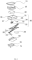
- the hidden top laser radar integrated box includes at least an outer housing 10, a lifting/lowering device 20, a cleaning device 30, a laser radar 40, a controller 50, a lower cover plate 60, and a water tray 70.
- the laser radar 40, the lifting/lowering device 20, the cleaning device 30, and the controller 50 are all located between the outer housing 10 and the lower cover plate 60.
- the laser radar 40 is located above the lifting/lowering device 20, and the lifting/lowering device 20 can be extended or shortened under a control of the controller 50, driving the laser radar 40 to extend outside or retract into the vehicle.
- the cleaning device 30 is located on two opposite sides of the laser radar 40, the lower cover plate 60 is located in the water tray 70, and the controller 50 is connected to an autonomous driving domain controller or an advanced auxiliary driving domain controller through a first cable.
- the lifting/lowering device 20 includes at least a driving device 21 and a lifting/lowering platform 22 connected to the driving device 21.
- the driving device 21 includes a motor 211, a gear 212, and a rotating shaft 213.
- the lifting/lowering platform 22 includes a screw rod 221, a first lifting/lowering rod 222, a second lifting/lowering rod 223, a supporting rod 224, an upper guide block 225, two lower guide blocks 226, and two bracket 227.
- one end of the rotating shaft 213 is connected to an output shaft of the motor 211, and the other end of the rotating shaft 213 is equipped with a plurality of teeth.
- the gear 212 is located at one end of the screw rod 221, and the teeth at the other end of the rotating shaft 213 engage with the gear 212 on the screw rod 221. Under the drive of the motor 211, the screw rod 221 is driven to rotate.
- first lifting/lowering rod 222 and the second lifting/lowering rod 223 are crossed and pivotally connected with each other.
- An upper end of the first lifting/lowering rod 222 is pivotally connected with one bracket 227
- an upper end of the second lifting/lowering rod 223 is pivotally connected with the upper guide block 225.
- Lower ends of the first lifting/lowering rod 222 and the second lifting/lowering rod 223 are both pivotally connected with the lower guide blocks 226.
- the upper guide block 225 is provided with a small hole, and one end of the supporting rod 224 passes through the small hole of the upper guide block 225, and is slidably connected to the upper guide block 225.
- the lower guide block 226 is also provided with a small hole.
- the two opposite ends of the screw rod 221 pass through the small holes of the lower guide blocks 226, and the end of the screw rod 221 near the motor 211 is threaded with a corresponding lower guide block 226.
- the motor 211 drives the screw rod 221 to rotate
- the lower guide block 226, which is threaded to the screw rod 221 undergoes a relative motion with the screw rod 221, driving a bottom end of the first lifting/lowering rod 222 to move along the screw rod 221, thereby changing a vertical height of the first lifting/lowering rod 222 and achieving a lifting/lowering function.
- Both ends of the supporting rod 224 are fixed with the brackets 227, which are connected to the cleaning device 30 and the laser radar 40. Therefore, the lifting/lowering platform 22 can drive the cleaning device 30 and the laser radar 40 to go up and down.
- the lifting/lowering device 20 is not limited to the lifting/lowering device 20 described in this embodiment. Any device with lifting/lowering function can replace the lifting/lowering device 20 of this embodiment.
- the specific structure of the lifting/lowering device in the existing technology will not be described in the present document.
- the device that extends the laser radar 40 outside or hides the laser radar 40 inside of the vehicle roof in the present document is not limited to the lifting/lowering device 20 described in this embodiment, but can also be a flipping or rotating device.
- the flipping or rotating device can flip or rotate around an axis on one side of a vehicle roof opening and be fixed with the laser radar 40. During the rotation process, the laser radar 40 can be rotated outside or inside of the vehicle roof.
- the specific structure of the flipping or rotating device in the prior art will not be further described in the present document.
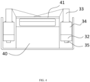
- the cleaning device 30 includes at least a fixing frame 31, an electromagnetic valve 32, a nozzle 33, a connecting portion 34, and a water inlet 35.
- the laser radar 20 is arranged on the fixing frame 31, and both sides of the fixing frame 31 is provided with a combination structure 311 of the electromagnetic valve 32, the nozzle 33, the connecting portion 34, and the water inlet 35.
- one end of the electromagnetic valve 32 is connected to the connecting portion 34, and the other end of the electromagnetic valve 32 is connected to the water inlet 35 to control the opening and closing of the water inlet 35.
- a pipeline connected to the water inlet 35 is connected to a vehicle water circuit.
- the nozzle 33 is connected to the connecting portion 34, and the nozzle 33 has a telescopic function. When the nozzle 33 is not in use, it retracts back into the interior of the connecting portion 34. When the nozzle 33 is in use, it extends out of the connecting portion 34 through the action of water pressure.
- the nozzle 33 can be a telescopic structure that can be expanded or retracted relative to the connecting portion 34 or be a fixed structure directly fixed to the connecting portion 34.
- the nozzle 33 is a telescopic structure.
- one side of the laser radar 40 is fixed with a mirror 41, and the other side of the laser radar 40 is connected with a second cable.
- the second cable is connected to the autonomous driving domain controller or the advanced auxiliary driving domain controller.
- the second cable may transmit a signal to the autonomous driving domain controller or the advanced auxiliary driving domain controller.
- the autonomous driving domain controller or the advanced auxiliary driving domain controller sends a cleaning signal to the electromagnetic valve 32.
- the electromagnetic valve 32 opens, and the nozzle 33 extends out to spray water on the mirror 41 for cleaning work.
- the figure shows an extension state of the nozzle 33, and the dashed line shows a spraying range, it can be seen that the water sprayed by the nozzles 33 on both sides can cover the entire mirror 41.
- the outer housing 10 is equipped with multiple windows, including a mirror window, a nozzle window, a second cable window of the laser radar, a first cable window of the controller, and a water pipe window of the water inlet, which are not shown in Figure 2 .
- the water tray 70 is further equipped with a drainage outlet 71, which is connected to a water pipe connected to the vehicle water circuit. After the cleaning device 30 completes cleaning, sewage will accumulate in the water tray 70 and be discharged into a vehicle drainage channel through the drainage outlet 71.
- the water tray 70 is fixed inside of a roof cover 80 (see Figure 1 ).
- a sealing ring 11 is disposed around a top portion of the outer housing 10.
- the upper surface of the outer housing 10 is coplanar with a top surface around an opening of the roof cover 80.
- the sealing ring 11 contacts with the surrounding area of the opening to prevent rainwater from entering the hidden top laser radar integrated box to protect the laser radar 40.
- the hidden top laser radar integrated box provided by the present document can be installed on the front and the rear sides of the roof cover 80, and the quantity of the hidden top laser radar integrated box can be increased or decreased as needed, allowing for simultaneous sensing the environment on the front and the rear sides of the vehicle.
- the working principle of the hidden top laser radar integrated box is as follows: when the user has driving requirements, the automatic driving domain controller or the advanced auxiliary driving domain controller sends a signal to open the top laser radar integrated box, the controller 50 inside the integrated box drives the motor 211 to rotate forward, the lifting/lowering device 20 starts to work, and the motor 211 drives the screw rod 221 to rotate through the gear 212, the first lifting/lowering rod 222 and the second lifting/lowering rod 223 drive the laser radar 40 and the cleaning device 30 to rise.
- the laser radar 40 and the cleaning device 30 rise to the outer side of the roof cover 80, the laser radar 40 begins to work.
- a dirt signal will be sent to the autonomous driving domain controller or the advanced auxiliary driving domain controller.
- the autonomous driving domain controller or the advanced auxiliary driving domain controller will send a cleaning signal to the controller 50 inside the integrated box, and the autonomous driving domain controller or the advanced auxiliary driving domain controller will drive the cleaning water pump to pressurize the water in the vehicle water circuit.
- the controller 50 inside the integrated box drives the cleaning device 30 to start working, the electromagnetic valve 32 opens, and the nozzle 33 sprays water to clean the mirror 41 of the laser radar 40. After the cleaning is completed, the electromagnetic valve 32 closes, and the drainage port 71 discharges the accumulated sewage to the water tray 70.
- the autonomous driving domain controller or the advanced auxiliary driving domain controller sends a signal to close the top laser radar integrated box.
- the controller 50 inside the integrated box drives the motor 211 to rotate in a reverse direction, and the top laser radar integrated box descends and closes.
- the hidden top laser radar integrated box provided by the present document has the following advantages: it is designed at a vehicle roof, a position of which is relatively high and makes the laser radar not easily obstructed or destroyed and have a wide field of view, and further can expand the view field of the laser radar to a maximum extent, thereby improving environmental perception effect of the laser radar, and solving the heat dissipation problem caused by radar operation through natural wind cooling.
- the hidden top laser radar integrated box has a hidden function.
- the laser radar When the laser radar is in standby mode, the laser radar, the lifting/lowering device, and the cleaning device are all hidden inside the roof cover of the vehicle, which enhances the overall feel and aesthetics of the vehicle, and a mirror surface of the laser radar is not easy to come into contact with soil and other dirt, thereby implementing an active cleaning function of the laser radar, improving the user experience.
- the present document further provides a vehicle, which includes the hidden top laser radar integrated box as described above.
- Other technical features of the vehicle have been disclosed in the existing technology and will not be repeated here.
Landscapes
- Engineering & Computer Science (AREA)
- Physics & Mathematics (AREA)
- Computer Networks & Wireless Communication (AREA)
- General Physics & Mathematics (AREA)
- Radar, Positioning & Navigation (AREA)
- Remote Sensing (AREA)
- Electromagnetism (AREA)
- Mechanical Engineering (AREA)
- Optical Radar Systems And Details Thereof (AREA)
Abstract
Description
- The present document relates to a field of laser radar technology, in particular to a hidden top laser radar integrated box and a vehicle having the same.
- Laser radar is an important sensor for achieving high-level intelligent driving and autonomous driving. The use of laser radar can make up the shortcomings of cameras and millimeter wave radar. Compared to cameras, it can build a more realistic 3D environment without relying on ambient light. Compared to millimeter wave radar, it has higher resolution and more accurate object recognition abilities.
- At present, limited by the size of the laser device and the area of the laser emitting (receiving) mirror, the overall size of laser radar is larger than that of cameras and millimeter wave radars. Therefore, it is difficult to arrange on the vehicle and is easily limited by layout and configuration of the vehicle.
- There are some shortcomings in the existing technologies:
- 1. The applied fixing device for the laser radar protrudes out from a roof surface of the vehicle, which affects the overall appearance of the vehicle and brings heat dissipation issues of the laser radar.
- 2. The protrusion radar structure increases the windward area and the wind resistance of the vehicle, and is not benefit for the vehicle endurance.
- 3. There is no active cleaning mechanism. If dirt such as soil and insect bodies covers the surface of the laser radar during the autonomous driving process, it will affect the normal operation of the radar and lead to the degradation of the autonomous driving function.
- 4. The single laser radar on the vehicle roof can only sense the forward field of the view environment.
- 5. The applied fixing device for the laser radar exposes the laser radar lens outside, while the laser radar lens is mostly made of PC or glass material, with a hardness less than sand and gravel, which brings a higher risk of being scratched during use.
- In view of the above problems, the present document provides a hidden top laser radar integrated box and a vehicle having the same, which solves the problem of limited view field of a single laser radar and inability to sense the rear environment of the vehicle, simultaneously meets the requirements for beautiful roof configuration and enhances the technology sense of the vehicle, and integrates a hidden cleaning system to improve user experience.
- The present document provides a hidden top laser radar integrated box, which includes at least an outer housing, a lifting/lowering device, a laser radar, a controller, and a lower cover plate. The lifting/lowering device, the laser radar, and the controller are located between the outer housing and the lower cover plate, and the laser radar is located above the lifting/lowering device. The lifting/lowering device is capable of being extended or shortened under a control of the controller, driving the laser radar to extend outside or retract into the vehicle.
- Furthermore, the lifting/lowering device includes at least a driving device and a lifting/lowering platform connected to the driving device. The driving device includes a motor, while the lifting/lowering platform includes a screw rod, a first lifting/lowering rod, a second lifting/lowering rod, and a supporting rod. The first lifting/lowering rod and the second lifting/lowering rod are crossed and pivotally connected with each other. The screw rod is connected to lower parts of the first lifting/lowering rod and the second lifting/lowering rod, The supporting rod is connected to upper parts of the first lifting/lowering rod and the second lifting/lowering rod, and the screw rod is connected to an output shaft of the motor through transmission, so that a distance between opposite ends of the first lifting/lowering rod and the second lifting/lowering rod could increase or decrease under the driving of the motor, thereby extending or shortening the lifting/lowering platform.
- Furthermore, the driving device further includes a gear and a rotating shaft. One end of the rotating shaft is connected to the output shaft of the motor, and the other end the rotating shaft is provided with a plurality of teeth. The gear is located at one end of the screw rod, and the teeth at the other end of the rotating shaft engage with the gears on the screw rod, driving the screw rod to rotate under the drive of the motor.
- Furthermore, the lifting/lowering platform further includes an upper guide block and a lower guide block. Upper ends of the first and the second lifting/lowering rods are both pivotally connected with the upper guide block, and lower ends of the first and the second lifting/lowering rods are both pivotally connected with the lower guide block. The upper guide block and the lower guide block are both provided with small holes, and two opposite ends of the supporting rod pass through the small holes of the upper guide block, and one end of the supporting rod is slidably connected to the upper guide block. Two opposite ends of the screw rod pass through the small holes of the lower guide block, and one end of the screw rod is threaded with the lower guide block.
- Furthermore, the hidden top laser radar integrated box further includes a cleaning device located on opposite sides of the laser radar. Two opposite ends of the supporting rod is provided with brackets, which are connected to the cleaning device and the laser radar.
- Furthermore, the cleaning device includes at least a fixing frame, an electromagnetic valve, a nozzle, a connecting portion, and a water inlet. The fixing frame is connected to the laser radar, and the electromagnetic valve, the nozzle, the connecting portion, and the water inlet are arranged on the fixing frame. One end of the electromagnetic valve is connected to the connecting portion, and the other end of the electromagnetic valve is connected to the water inlet. A pipeline connected to the water inlet is connected to a vehicle water circuit. The nozzle is connected to the connecting portion, and is provided with a telescopic function.
- Furthermore, one side of the laser radar is provided with a mirror surface, and the other side of the laser radar is connected with a second cable, which is connected to an autonomous driving domain controller or an advanced auxiliary driving domain controller.
- Furthermore, a sealing ring is further provided around a top portion of the outer housing.
- Furthermore, the hidden top laser radar integrated box further includes a water tray. The lower cover plate is located within the water tray, and a drainage outlet is further provided on the water tray. A water pipe connected to the drainage outlet is connected to a vehicle water circuit.
- The present document further provides a vehicle, which includes the hidden top laser radar integrated box as described above.
- The present document provides a hidden top laser radar integrated box being designed at a vehicle roof, a position of which is relatively high and makes the laser radar not easily obstructed or destroyed and have a wide field of view, and further can expand the view field of the laser radar to a maximum extent, thereby improving environmental perception effect of the laser radar, and solving the heat dissipation problem caused by radar operation through natural wind cooling. The hidden top laser radar integrated box has a hidden function. When the laser radar is in standby mode, the laser radar, the lifting/lowering device, and the cleaning device are all hidden inside a roof cover of the vehicle, which enhances the overall feel and aesthetics of the vehicle, and a mirror surface of the laser radar is not easy to come into contact with soil and other dirt, thereby implementing an active cleaning function of the laser radar, and improving the user experience.
-
-
Figure 1 is a schematic view showing an installation position of the hidden top laser radar integrated box on a vehicle roof according to an embodiment of the present document. -
Figure 2 is an exploded view of the hidden top laser radar integrated box according to an embodiment the present document. -
Figure 3 is a schematic structural view of a lifting/lowering device in an embodiment of the present document. -
Figure 4 is a schematic top view of a cleaning device and a laser radar in an embodiment of the present document. - The specific embodiments of the present document will be further described in detail below with reference to the accompanying drawings and examples. The following examples are used to illustrate the present document, but are not used to limit the scope of the present document.
- In the description of the present document, it should be noted that, the orientation or positional relationship indicated in this description is based on the orientation or positional relationship shown in the drawings, and is only for the convenience of describing the present document and simplifying the description, rather than indicating or implying that the device or element must have a specific orientation, be constructed and operate in a specific orientation, and therefore should not be construed as a limitation of the present document.
- Please refer to
Figure 2 , the hidden top laser radar integrated box provided by the present document includes at least anouter housing 10, a lifting/lowering device 20, acleaning device 30, alaser radar 40, acontroller 50, alower cover plate 60, and awater tray 70. Thelaser radar 40, the lifting/loweringdevice 20, thecleaning device 30, and thecontroller 50 are all located between theouter housing 10 and thelower cover plate 60. Thelaser radar 40 is located above the lifting/loweringdevice 20, and the lifting/loweringdevice 20 can be extended or shortened under a control of thecontroller 50, driving thelaser radar 40 to extend outside or retract into the vehicle. Thecleaning device 30 is located on two opposite sides of thelaser radar 40, thelower cover plate 60 is located in thewater tray 70, and thecontroller 50 is connected to an autonomous driving domain controller or an advanced auxiliary driving domain controller through a first cable. - Specifically, please refer to
Figure 3 together, the lifting/loweringdevice 20 includes at least a drivingdevice 21 and a lifting/loweringplatform 22 connected to the drivingdevice 21. The drivingdevice 21 includes amotor 211, agear 212, and arotating shaft 213. The lifting/loweringplatform 22 includes ascrew rod 221, a first lifting/loweringrod 222, a second lifting/loweringrod 223, a supportingrod 224, anupper guide block 225, two lower guide blocks 226, and twobracket 227. - Furthermore, one end of the
rotating shaft 213 is connected to an output shaft of themotor 211, and the other end of therotating shaft 213 is equipped with a plurality of teeth. Thegear 212 is located at one end of thescrew rod 221, and the teeth at the other end of therotating shaft 213 engage with thegear 212 on thescrew rod 221. Under the drive of themotor 211, thescrew rod 221 is driven to rotate. - Furthermore, the first lifting/lowering
rod 222 and the second lifting/loweringrod 223 are crossed and pivotally connected with each other. An upper end of the first lifting/loweringrod 222 is pivotally connected with onebracket 227, an upper end of the second lifting/loweringrod 223 is pivotally connected with theupper guide block 225. Lower ends of the first lifting/loweringrod 222 and the second lifting/loweringrod 223 are both pivotally connected with the lower guide blocks 226. Theupper guide block 225 is provided with a small hole, and one end of the supportingrod 224 passes through the small hole of theupper guide block 225, and is slidably connected to theupper guide block 225. Thelower guide block 226 is also provided with a small hole. The two opposite ends of thescrew rod 221 pass through the small holes of the lower guide blocks 226, and the end of thescrew rod 221 near themotor 211 is threaded with a correspondinglower guide block 226. When themotor 211 drives thescrew rod 221 to rotate, thelower guide block 226, which is threaded to thescrew rod 221, undergoes a relative motion with thescrew rod 221, driving a bottom end of the first lifting/loweringrod 222 to move along thescrew rod 221, thereby changing a vertical height of the first lifting/loweringrod 222 and achieving a lifting/lowering function. Both ends of the supportingrod 224 are fixed with thebrackets 227, which are connected to thecleaning device 30 and thelaser radar 40. Therefore, the lifting/loweringplatform 22 can drive thecleaning device 30 and thelaser radar 40 to go up and down. - It should be noted that the lifting/lowering
device 20 is not limited to the lifting/loweringdevice 20 described in this embodiment. Any device with lifting/lowering function can replace the lifting/loweringdevice 20 of this embodiment. The specific structure of the lifting/lowering device in the existing technology will not be described in the present document. - It should be further noted that the device that extends the
laser radar 40 outside or hides thelaser radar 40 inside of the vehicle roof in the present document is not limited to the lifting/loweringdevice 20 described in this embodiment, but can also be a flipping or rotating device. The flipping or rotating device can flip or rotate around an axis on one side of a vehicle roof opening and be fixed with thelaser radar 40. During the rotation process, thelaser radar 40 can be rotated outside or inside of the vehicle roof. The specific structure of the flipping or rotating device in the prior art will not be further described in the present document. - Furthermore, please refer to
Figure 4 , thecleaning device 30 includes at least a fixingframe 31, anelectromagnetic valve 32, anozzle 33, a connectingportion 34, and awater inlet 35. Thelaser radar 20 is arranged on the fixingframe 31, and both sides of the fixingframe 31 is provided with a combination structure 311 of theelectromagnetic valve 32, thenozzle 33, the connectingportion 34, and thewater inlet 35. Specifically, one end of theelectromagnetic valve 32 is connected to the connectingportion 34, and the other end of theelectromagnetic valve 32 is connected to thewater inlet 35 to control the opening and closing of thewater inlet 35. A pipeline connected to thewater inlet 35 is connected to a vehicle water circuit. Thenozzle 33 is connected to the connectingportion 34, and thenozzle 33 has a telescopic function. When thenozzle 33 is not in use, it retracts back into the interior of the connectingportion 34. When thenozzle 33 is in use, it extends out of the connectingportion 34 through the action of water pressure. - It should be noted that the
nozzle 33 can be a telescopic structure that can be expanded or retracted relative to the connectingportion 34 or be a fixed structure directly fixed to the connectingportion 34. In this embodiment, thenozzle 33 is a telescopic structure. - Please refer to
Figure 4 , one side of thelaser radar 40 is fixed with a mirror 41, and the other side of thelaser radar 40 is connected with a second cable. The second cable is connected to the autonomous driving domain controller or the advanced auxiliary driving domain controller. When thelaser radar 40 detects that the mirror 41 is dirtied, the second cable may transmit a signal to the autonomous driving domain controller or the advanced auxiliary driving domain controller. The autonomous driving domain controller or the advanced auxiliary driving domain controller sends a cleaning signal to theelectromagnetic valve 32. Theelectromagnetic valve 32 opens, and thenozzle 33 extends out to spray water on the mirror 41 for cleaning work. The figure shows an extension state of thenozzle 33, and the dashed line shows a spraying range, it can be seen that the water sprayed by thenozzles 33 on both sides can cover the entire mirror 41. - It should be noted that as shown in
Figure 2 , theouter housing 10 is equipped with multiple windows, including a mirror window, a nozzle window, a second cable window of the laser radar, a first cable window of the controller, and a water pipe window of the water inlet, which are not shown inFigure 2 . - Furthermore, the
water tray 70 is further equipped with adrainage outlet 71, which is connected to a water pipe connected to the vehicle water circuit. After thecleaning device 30 completes cleaning, sewage will accumulate in thewater tray 70 and be discharged into a vehicle drainage channel through thedrainage outlet 71. Thewater tray 70 is fixed inside of a roof cover 80 (seeFigure 1 ). - Furthermore, please refer to
Figure 2 , a sealingring 11 is disposed around a top portion of theouter housing 10. When theouter housing 10 is retracted, the upper surface of theouter housing 10 is coplanar with a top surface around an opening of theroof cover 80. The sealingring 11 contacts with the surrounding area of the opening to prevent rainwater from entering the hidden top laser radar integrated box to protect thelaser radar 40. - It should be noted that as shown in
Figure 1 , the hidden top laser radar integrated box provided by the present document can be installed on the front and the rear sides of theroof cover 80, and the quantity of the hidden top laser radar integrated box can be increased or decreased as needed, allowing for simultaneous sensing the environment on the front and the rear sides of the vehicle. - The working principle of the hidden top laser radar integrated box provided by the present document is as follows: when the user has driving requirements, the automatic driving domain controller or the advanced auxiliary driving domain controller sends a signal to open the top laser radar integrated box, the
controller 50 inside the integrated box drives themotor 211 to rotate forward, the lifting/loweringdevice 20 starts to work, and themotor 211 drives thescrew rod 221 to rotate through thegear 212, the first lifting/loweringrod 222 and the second lifting/loweringrod 223 drive thelaser radar 40 and thecleaning device 30 to rise. When thelaser radar 40 and thecleaning device 30 rise to the outer side of theroof cover 80, thelaser radar 40 begins to work. When thelaser radar 40 detects that the mirror 41 is dirtied, a dirt signal will be sent to the autonomous driving domain controller or the advanced auxiliary driving domain controller. The autonomous driving domain controller or the advanced auxiliary driving domain controller will send a cleaning signal to thecontroller 50 inside the integrated box, and the autonomous driving domain controller or the advanced auxiliary driving domain controller will drive the cleaning water pump to pressurize the water in the vehicle water circuit. After a delay of a period of time, thecontroller 50 inside the integrated box drives thecleaning device 30 to start working, theelectromagnetic valve 32 opens, and thenozzle 33 sprays water to clean the mirror 41 of thelaser radar 40. After the cleaning is completed, theelectromagnetic valve 32 closes, and thedrainage port 71 discharges the accumulated sewage to thewater tray 70. When the driving function is exited, the autonomous driving domain controller or the advanced auxiliary driving domain controller sends a signal to close the top laser radar integrated box. Thecontroller 50 inside the integrated box drives themotor 211 to rotate in a reverse direction, and the top laser radar integrated box descends and closes. - From the above description, it can be seen that the hidden top laser radar integrated box provided by the present document has the following advantages: it is designed at a vehicle roof, a position of which is relatively high and makes the laser radar not easily obstructed or destroyed and have a wide field of view, and further can expand the view field of the laser radar to a maximum extent, thereby improving environmental perception effect of the laser radar, and solving the heat dissipation problem caused by radar operation through natural wind cooling. The hidden top laser radar integrated box has a hidden function. When the laser radar is in standby mode, the laser radar, the lifting/lowering device, and the cleaning device are all hidden inside the roof cover of the vehicle, which enhances the overall feel and aesthetics of the vehicle, and a mirror surface of the laser radar is not easy to come into contact with soil and other dirt, thereby implementing an active cleaning function of the laser radar, improving the user experience.
- The present document further provides a vehicle, which includes the hidden top laser radar integrated box as described above. Other technical features of the vehicle have been disclosed in the existing technology and will not be repeated here.
- The above is only the specific implementation method of the present document, but the protection scope of the present document is not limited to this. Other variations or replacement that can be easily obtained by those having ordinary skill in the art on the basis of the disclosure of the present document should be covered within the protection scope of the present document. Accordingly, the protection scope of the present document should be based on the protection scope of the claims.
Claims (10)
- A hidden top laser radar integrated box, characterized in that comprising at least an outer housing (10), a lifting/lowering device (20), a laser radar (40), a controller (50), and a lower cover plate (60), the lifting/lowering device (20), the laser radar (40), and the controller (50) being located between the outer housing (10) and the lower cover plate (60), and the laser radar (40) being located above the lifting/lowering device (20), the lifting/lowering device (20) being scalable under a control of the controller (50), driving the laser radar (40) to extend outside or retract into a vehicle.
- The hidden top laser radar integrated box according to claim 1, wherein the lifting/lowering device (20) comprises at least a driving device (21) and a lifting/lowering platform (22) connected to the driving device (21), the driving device (21) comprises a motor (211), and the lifting/lowering platform (22) comprises a screw rod (221), a first lifting/lowering rod (222), a second lifting/lowering rod (223), and a supporting rod (224), the first lifting/lowering rod (222) and the second lifting/lowering rod (223) are crossed and pivotally connected with each other, the screw rod (221) is connected to lower parts of the first lifting/lowering rod (222) and the second lifting/lowering rod (223), the supporting rod (224) is connected to upper parts of the first lifting/lowering rod (222) and the second lifting/lowering rod (223), and the screw rod (221) is connected to an output shaft of the motor (211) through transmission, a distance between opposite ends of the first lifting/lowering rod (222) and the second lifting/lowering rod (223) is increased or decreased under a drive of the motor (211), thereby extending or shortening the lifting/lowering platform (22).
- The hidden top laser radar integrated box according to claim 2, wherein the driving device (21) further comprises a gear (212) and a rotating shaft (213), one end of the rotating shaft (213) is connected to the output shaft of the motor (211), and the other end of the rotating shaft (213) is provided with a plurality of teeth, the gear (212) is located at one end of the screw rod (221), the teeth at the other end of the rotating shaft (213) engage with the gear (212) on the screw rod (221), and are driven by the motor (211) to drive the screw rod (221) to rotate.
- The hidden top laser radar integrated box according to claim 2, wherein the lifting/lowering platform (22) further comprises an upper guide block (225) and a lower guide block (226), upper ends of the first lifting/lowering rods (222) and the second lifting/lowering rods (223) are both pivotally connected with the upper guide block (225), and lower ends of the first lifting/lowering rods (222) and the second lifting/lowering rods (223) are both pivotally connected with the lower guide block (226), the upper guide block (225) and the lower guide block (226) are both provided with small holes, two opposite ends of the supporting rod (224) pass through the small holes of the upper guide block (225), and one end of the supporting rod (224) is slidably connected to the upper guide block (225), two opposite ends of the screw rod (221) pass through the small holes of the lower guide block (226), and one end of the screw rod (221) is threaded with the lower guide block (226).
- The hidden top laser radar integrated box according to claim 2, wherein the hidden top laser radar integrated box further comprises a cleaning device (30), which is located on opposite sides of the laser radar (40), and two opposite ends of the supporting rod (224) are provided with brackets (227), which are connected to the cleaning device (30) and the laser radar (40).
- The hidden top laser radar integrated box according to claim 5, wherein the cleaning device (30) comprises at least a fixing frame (31), an electromagnetic valve (32), a nozzle (33), a connecting portion (34), and a water inlet (35), the fixing frame (31) is connected to the laser radar (40), and the electromagnetic valve (32), the nozzle (33), the connecting portion (34), and the water inlet (35) are arranged on the fixing frame (31), one end of the electromagnetic valve (32) is connected to the connecting portion (34), and the other end of the electromagnetic valve (32) is connected to the water inlet (35), a pipeline connected to the water inlet (35) is connected to a vehicle water circuit, and the nozzle (33) is connected to the connecting portion (34), and the nozzle (33) has a telescopic function.
- The hidden top laser radar integrated box according to claim 1, wherein one side of the laser radar (40) is provided with a mirror (41), and the other side of the laser radar (40) is connected with a second cable, which is connected to an autonomous driving domain controller or an advanced auxiliary driving domain controller.
- The hidden top laser radar integrated box according to claim 1, wherein a sealing ring (11) is provided around a top portion of the outer housing (10).
- The hidden top laser radar integrated box according to claim 1, wherein the hidden top laser radar integrated box further comprises a water tray (70), the lower cover plate (60) is located within the water tray (70), and a drainage outlet (71) is provided on the water tray (70), a water pipe connected to the drainage outlet (71) is connected to a vehicle water circuit.
- A vehicle, characterized in that comprising a hidden top laser radar integrated box according to any one of claims 1-9.
Applications Claiming Priority (2)
| Application Number | Priority Date | Filing Date | Title |
|---|---|---|---|
| CN202121015524.XU CN215474853U (en) | 2021-05-12 | 2021-05-12 | Hidden top laser radar integrated box and have its vehicle |
| PCT/CN2022/082891 WO2022237343A1 (en) | 2021-05-12 | 2022-03-24 | Hidden top laser radar integrated box and vehicle having same |
Publications (2)
| Publication Number | Publication Date |
|---|---|
| EP4339032A1 true EP4339032A1 (en) | 2024-03-20 |
| EP4339032A4 EP4339032A4 (en) | 2025-05-14 |
Family
ID=79777950
Family Applications (1)
| Application Number | Title | Priority Date | Filing Date |
|---|---|---|---|
| EP22806313.7A Pending EP4339032A4 (en) | 2021-05-12 | 2022-03-24 | INTEGRATED LASER RADAR BOX WITH HIDDEN TOP AND VEHICLE WITH IT |
Country Status (3)
| Country | Link |
|---|---|
| EP (1) | EP4339032A4 (en) |
| CN (1) | CN215474853U (en) |
| WO (1) | WO2022237343A1 (en) |
Families Citing this family (9)
| Publication number | Priority date | Publication date | Assignee | Title |
|---|---|---|---|---|
| CN215474853U (en) * | 2021-05-12 | 2022-01-11 | 武汉路特斯汽车有限公司 | Hidden top laser radar integrated box and have its vehicle |
| CN114407790B (en) * | 2022-01-25 | 2024-07-23 | 浙江吉利控股集团有限公司 | Automobile and environment sensing device thereof |
| CN114407789B (en) * | 2022-01-25 | 2024-05-31 | 浙江吉利控股集团有限公司 | Automobile and environment sensing device thereof |
| CN114509739A (en) * | 2022-02-23 | 2022-05-17 | 宁波信泰机械有限公司 | Telescopic cleaning assembly and laser radar |
| CN114721009A (en) * | 2022-03-31 | 2022-07-08 | 岚图汽车科技有限公司 | Concealed laser radar |
| CN115489440A (en) * | 2022-08-09 | 2022-12-20 | 岚图汽车科技有限公司 | A laser radar installation device |
| CN115973431A (en) * | 2022-12-19 | 2023-04-18 | 广东汇天航空航天科技有限公司 | Radar protection mechanism, radar system and aircraft of aircraft |
| CN117784027B (en) * | 2024-02-27 | 2024-05-14 | 泰兴市依科攀船舶设备股份有限公司 | Electric lifting rotary radar seat platform |
| CN119828107B (en) * | 2025-01-20 | 2025-07-18 | 苏州冠普电子有限公司 | Height-limiting detection radar for movable lifting platform |
Family Cites Families (8)
| Publication number | Priority date | Publication date | Assignee | Title |
|---|---|---|---|---|
| CN206217814U (en) * | 2016-12-08 | 2017-06-06 | 鄂尔多斯市普渡科技有限公司 | A kind of pilotless automobile laser radar rain insensitive device |
| CN209242667U (en) * | 2018-07-30 | 2019-08-13 | 连云港和昌机械有限公司 | A kind of full automatic car entrucking oil filling riser |
| CN109532629B (en) * | 2018-12-24 | 2025-01-14 | 河南森源鸿马电动汽车有限公司 | Mobile drone defense vehicle |
| CN110244280A (en) * | 2019-06-28 | 2019-09-17 | 戴姆勒股份公司 | The automatic safety device of laser radar for automobile |
| CN110428209B (en) * | 2019-08-16 | 2020-10-27 | 灵动科技(北京)有限公司 | Checking equipment, checking management system and checking method |
| CN112744162A (en) * | 2020-12-28 | 2021-05-04 | 广东科学技术职业学院 | Unmanned vehicle with liftable laser radar |
| CN112606774B (en) * | 2020-12-28 | 2023-01-31 | 广东科学技术职业学院 | But self-cleaning laser radar's unmanned vehicle |
| CN215474853U (en) * | 2021-05-12 | 2022-01-11 | 武汉路特斯汽车有限公司 | Hidden top laser radar integrated box and have its vehicle |
-
2021
- 2021-05-12 CN CN202121015524.XU patent/CN215474853U/en active Active
-
2022
- 2022-03-24 WO PCT/CN2022/082891 patent/WO2022237343A1/en not_active Ceased
- 2022-03-24 EP EP22806313.7A patent/EP4339032A4/en active Pending
Also Published As
| Publication number | Publication date |
|---|---|
| WO2022237343A1 (en) | 2022-11-17 |
| EP4339032A4 (en) | 2025-05-14 |
| CN215474853U (en) | 2022-01-11 |
Similar Documents
| Publication | Publication Date | Title |
|---|---|---|
| EP4339032A1 (en) | Hidden top laser radar integrated box and vehicle having same | |
| WO2022237848A1 (en) | Laser radar integrated box, cleaning device, and vehicle | |
| WO2022237342A1 (en) | Concealed integrated device of corner laser radars, and vehicle having same | |
| CN109898876A (en) | A kind of intelligence facade scavenging machine | |
| CN115320505A (en) | Hidden electronic exterior rearview mirror, vehicle and control method thereof | |
| CN118303205A (en) | Robot and cleaning control method thereof | |
| US20240077575A1 (en) | Laser radar integrated device and vehicle provided with same | |
| CN213186262U (en) | Dust removal type traffic surveillance camera head | |
| CN114833099A (en) | Intelligent system of digital multifunctional camera of high-speed toll gate | |
| CN114954361B (en) | Hidden windshield wiper and vehicle | |
| JP7356410B2 (en) | Sensor system with cleaner for vehicles | |
| WO2023093712A1 (en) | Vehicle laser radar supporting device and vehicle | |
| CN221961899U (en) | A monitoring device for environmental monitoring | |
| CN116351749B (en) | Automatic loading vehicle contour detection device capable of automatically removing dust | |
| CN218124796U (en) | Nozzle structure for camera and camera module | |
| CN115845529B (en) | A spray inspection robot based on a multi-purpose dock | |
| CN110901595A (en) | Waterproof and dustproof all-liquid-crystal instrument panel for automobile | |
| US20250383432A1 (en) | Sensor protection apparatus | |
| CN213725510U (en) | Fog gun machine convenient to control turned angle | |
| CN214040507U (en) | A water spray test device for water tightness detection of doors and windows | |
| CN112122184B (en) | Base detection device for building construction | |
| CN114407789A (en) | Automobile and environment sensing device thereof | |
| CN223877993U (en) | Rearview mirror cleaning device, traditional rearview mirror and electronic rearview mirror | |
| CN219406397U (en) | Cleaning mechanism of vehicle detection equipment and vehicle | |
| CN223660733U (en) | Environment-friendly municipal engineering watering device |
Legal Events
| Date | Code | Title | Description |
|---|---|---|---|
| STAA | Information on the status of an ep patent application or granted ep patent |
Free format text: STATUS: THE INTERNATIONAL PUBLICATION HAS BEEN MADE |
|
| PUAI | Public reference made under article 153(3) epc to a published international application that has entered the european phase |
Free format text: ORIGINAL CODE: 0009012 |
|
| STAA | Information on the status of an ep patent application or granted ep patent |
Free format text: STATUS: REQUEST FOR EXAMINATION WAS MADE |
|
| 17P | Request for examination filed |
Effective date: 20231109 |
|
| AK | Designated contracting states |
Kind code of ref document: A1 Designated state(s): AL AT BE BG CH CY CZ DE DK EE ES FI FR GB GR HR HU IE IS IT LI LT LU LV MC MK MT NL NO PL PT RO RS SE SI SK SM TR |
|
| DAV | Request for validation of the european patent (deleted) | ||
| DAX | Request for extension of the european patent (deleted) | ||
| A4 | Supplementary search report drawn up and despatched |
Effective date: 20250414 |
|
| RIC1 | Information provided on ipc code assigned before grant |
Ipc: G01S 17/931 20200101ALI20250408BHEP Ipc: G01S 7/481 20060101ALI20250408BHEP Ipc: B60S 1/56 20060101ALI20250408BHEP Ipc: B60S 1/52 20060101ALI20250408BHEP Ipc: H05K 7/20 20060101ALI20250408BHEP Ipc: B08B 3/02 20060101ALI20250408BHEP Ipc: B60R 11/00 20060101AFI20250408BHEP |