EP4338962A1 - Active energy irradiation device and inkjet printer - Google Patents
Active energy irradiation device and inkjet printer Download PDFInfo
- Publication number
- EP4338962A1 EP4338962A1 EP22860875.8A EP22860875A EP4338962A1 EP 4338962 A1 EP4338962 A1 EP 4338962A1 EP 22860875 A EP22860875 A EP 22860875A EP 4338962 A1 EP4338962 A1 EP 4338962A1
- Authority
- EP
- European Patent Office
- Prior art keywords
- filter
- active energy
- irradiation device
- energy irradiation
- housing
- Prior art date
- Legal status (The legal status is an assumption and is not a legal conclusion. Google has not performed a legal analysis and makes no representation as to the accuracy of the status listed.)
- Pending
Links
Images







Classifications
-
- B—PERFORMING OPERATIONS; TRANSPORTING
- B41—PRINTING; LINING MACHINES; TYPEWRITERS; STAMPS
- B41J—TYPEWRITERS; SELECTIVE PRINTING MECHANISMS, i.e. MECHANISMS PRINTING OTHERWISE THAN FROM A FORME; CORRECTION OF TYPOGRAPHICAL ERRORS
- B41J29/00—Details of, or accessories for, typewriters or selective printing mechanisms not otherwise provided for
- B41J29/377—Cooling or ventilating arrangements
-
- B—PERFORMING OPERATIONS; TRANSPORTING
- B41—PRINTING; LINING MACHINES; TYPEWRITERS; STAMPS
- B41J—TYPEWRITERS; SELECTIVE PRINTING MECHANISMS, i.e. MECHANISMS PRINTING OTHERWISE THAN FROM A FORME; CORRECTION OF TYPOGRAPHICAL ERRORS
- B41J11/00—Devices or arrangements of selective printing mechanisms, e.g. ink-jet printers or thermal printers, for supporting or handling copy material in sheet or web form
- B41J11/0015—Devices or arrangements of selective printing mechanisms, e.g. ink-jet printers or thermal printers, for supporting or handling copy material in sheet or web form for treating before, during or after printing or for uniform coating or laminating the copy material before or after printing
- B41J11/002—Curing or drying the ink on the copy materials, e.g. by heating or irradiating
- B41J11/0021—Curing or drying the ink on the copy materials, e.g. by heating or irradiating using irradiation
- B41J11/00214—Curing or drying the ink on the copy materials, e.g. by heating or irradiating using irradiation using UV radiation
-
- B—PERFORMING OPERATIONS; TRANSPORTING
- B41—PRINTING; LINING MACHINES; TYPEWRITERS; STAMPS
- B41J—TYPEWRITERS; SELECTIVE PRINTING MECHANISMS, i.e. MECHANISMS PRINTING OTHERWISE THAN FROM A FORME; CORRECTION OF TYPOGRAPHICAL ERRORS
- B41J11/00—Devices or arrangements of selective printing mechanisms, e.g. ink-jet printers or thermal printers, for supporting or handling copy material in sheet or web form
- B41J11/0015—Devices or arrangements of selective printing mechanisms, e.g. ink-jet printers or thermal printers, for supporting or handling copy material in sheet or web form for treating before, during or after printing or for uniform coating or laminating the copy material before or after printing
- B41J11/002—Curing or drying the ink on the copy materials, e.g. by heating or irradiating
- B41J11/0021—Curing or drying the ink on the copy materials, e.g. by heating or irradiating using irradiation
- B41J11/00218—Constructional details of the irradiation means, e.g. radiation source attached to reciprocating print head assembly or shutter means provided on the radiation source
-
- B—PERFORMING OPERATIONS; TRANSPORTING
- B41—PRINTING; LINING MACHINES; TYPEWRITERS; STAMPS
- B41J—TYPEWRITERS; SELECTIVE PRINTING MECHANISMS, i.e. MECHANISMS PRINTING OTHERWISE THAN FROM A FORME; CORRECTION OF TYPOGRAPHICAL ERRORS
- B41J2/00—Typewriters or selective printing mechanisms characterised by the printing or marking process for which they are designed
- B41J2/005—Typewriters or selective printing mechanisms characterised by the printing or marking process for which they are designed characterised by bringing liquid or particles selectively into contact with a printing material
- B41J2/01—Ink jet
-
- F—MECHANICAL ENGINEERING; LIGHTING; HEATING; WEAPONS; BLASTING
- F26—DRYING
- F26B—DRYING SOLID MATERIALS OR OBJECTS BY REMOVING LIQUID THEREFROM
- F26B13/00—Machines and apparatus for drying fabrics, fibres, yarns, or other materials in long lengths, with progressive movement
-
- F—MECHANICAL ENGINEERING; LIGHTING; HEATING; WEAPONS; BLASTING
- F26—DRYING
- F26B—DRYING SOLID MATERIALS OR OBJECTS BY REMOVING LIQUID THEREFROM
- F26B3/00—Drying solid materials or objects by processes involving the application of heat
- F26B3/28—Drying solid materials or objects by processes involving the application of heat by radiation, e.g. from the sun
-
- F—MECHANICAL ENGINEERING; LIGHTING; HEATING; WEAPONS; BLASTING
- F26—DRYING
- F26B—DRYING SOLID MATERIALS OR OBJECTS BY REMOVING LIQUID THEREFROM
- F26B3/00—Drying solid materials or objects by processes involving the application of heat
- F26B3/28—Drying solid materials or objects by processes involving the application of heat by radiation, e.g. from the sun
- F26B3/283—Drying solid materials or objects by processes involving the application of heat by radiation, e.g. from the sun in combination with convection
-
- B—PERFORMING OPERATIONS; TRANSPORTING
- B41—PRINTING; LINING MACHINES; TYPEWRITERS; STAMPS
- B41F—PRINTING MACHINES OR PRESSES
- B41F23/00—Devices for treating the surfaces of sheets, webs, or other articles in connection with printing
- B41F23/04—Devices for treating the surfaces of sheets, webs, or other articles in connection with printing by heat drying, by cooling, by applying powders
- B41F23/0403—Drying webs
- B41F23/0406—Drying webs by radiation
- B41F23/0409—Ultraviolet dryers
-
- B—PERFORMING OPERATIONS; TRANSPORTING
- B41—PRINTING; LINING MACHINES; TYPEWRITERS; STAMPS
- B41F—PRINTING MACHINES OR PRESSES
- B41F23/00—Devices for treating the surfaces of sheets, webs, or other articles in connection with printing
- B41F23/04—Devices for treating the surfaces of sheets, webs, or other articles in connection with printing by heat drying, by cooling, by applying powders
- B41F23/044—Drying sheets, e.g. between two printing stations
- B41F23/045—Drying sheets, e.g. between two printing stations by radiation
- B41F23/0453—Drying sheets, e.g. between two printing stations by radiation by ultraviolet dryers
Definitions
- the present disclosure relates to an active energy irradiation device and an inkjet printer.
- Patent Literature 1 describes a light irradiation device including a housing and a light source (irradiation unit) disposed in the housing.
- a light source irradiation unit
- an intake port through which air is sucked from an outside is provided in the housing, and the light source is cooled by the air flowing into the housing via a suction port.
- Patent Literature 1 Japanese Unexamined Patent Publication No. 2005-103845
- Foreign substances such as ink mist are floating in a device such as an injector printer in which the above-described active energy irradiation device is disposed.
- a filter that collects foreign substances contained in the air flowing into the housing may be attached.
- clogging of the filter progresses as a use time of the device increases, a flow rate of the air flowing into the housing decreases.
- a temperature of the irradiation unit rises (cooling is insufficient).
- An object of the present disclosure is to provide an active energy irradiation device and an inkjet printer capable of suppressing an increase in a temperature of an irradiation unit accompanying an increase in a use time.
- An active energy irradiation device includes a housing, an irradiation unit that is disposed in the housing, and is configured to irradiate active energy rays, a heat conduction member that is disposed in the housing, and is thermally connected to the irradiation unit, a first opening that is provided at the housing, and an air introduction unit that deflects air flowing into the housing along a first direction via the first opening to a second direction intersecting the first direction to introduce the air to the heat conduction member.
- the air introduction unit includes a partition that is provided to face the first opening in the housing, and a filter that is provided between the first opening and the partition, and collects foreign substances contained in the air, and the filter includes a first filter portion that is provided on the heat conduction member side to come into contact with the partition without being exposed from the first opening as viewed from the first direction.
- the air is introduced into the heat conduction member by the air introduction unit, the heat conduction member is cooled by the air, and the irradiation unit is cooled.
- the foreign substances contained in the air are collected and removed by the filter including the first filter portion.
- the air introduction unit the air flowing into the housing along the first direction via the first opening is deflected in the second direction intersecting the first direction and is introduced into the heat conduction member.
- a portion through which air easily passes on the deflected second direction side can be formed in a region (hereinafter, also referred to as a "filter exposure region") exposed from the first opening of the filter.
- the air flowing into the housing via the first opening does not uniformly pass through the entire filter exposure region, but mainly passes through a part thereof.
- a region through which air mainly passes transitions to another part of the filter exposure region, and this transition is repeated with the increase in the use time of the device.
- an entire region of the filter on the partition side comes into contact with the partition.
- the filter can be effectively supported by the partition.
- the filter may include a second filter portion that is provided on at least a side opposite to the heat conduction member side, and has a thickness in the first direction thinner than the first filter portion.
- a passage path thereof becomes long, and a resistance loss is likely to increase.
- the filter in a case where the air passes through the side opposite to the heat conduction member side of the filter, since the filter includes the second filter portion, the passage path of the filter can be shortened, and the resistance loss of the air can be reduced.
- the second filter portion may be configured such that the thickness in the first direction becomes thinner toward the side opposite to the heat conduction member side.
- the second filter portion may have a constant thickness thinner than the first filter portion.
- the active energy irradiation device may include a skirt portion that is disposed on the irradiation unit side from the first opening on an outer surface of the housing, and is provided to protrude in the first direction.
- the air containing the foreign substances such as ink mist present around the device can be efficiently guided to the first opening by the skirt portion.
- the filter may include a plurality of layers.
- a density of each of the plurality of layers in the filter is changed, and thus, collection performance of the foreign substances, the resistance loss of the air, and the like in the filter can be adjusted.
- the active energy irradiation device may include a second opening that is provided in the housing, and causes the air having passed through the heat conduction member to flow out of the housing.
- the air having cooled the heat conduction member can flow out of the housing via the second opening.
- the heat conduction member may be a heat sink.
- the irradiation unit can be cooled by using the heat sink as the heat conduction member.
- the irradiation unit may include a plurality of ultraviolet LEDs.
- ultraviolet rays can be irradiated as active energy.
- the filter may come into contact with the heat conduction member.
- the filter can be effectively supported by the heat conduction member.
- the first filter portion may be provided to cover a flow path of the air in the air introduction unit. In this case, the foreign substances contained in the air can be more reliably collected by the first filter portion.
- a mark indicating that a clogging ratio of the filter is a predetermined ratio may be provided to at least any one of the filter and the housing. In this case, it is possible to easily confirm whether or not clogging has transitioned to a predetermined ratio in the filter by referring to the mark.
- the active energy irradiation device may irradiate a printed matter to which ink adheres, as an object to be irradiated, and the filter is a filter of a color different from a color of the ink.
- the filter is a filter of a color different from a color of the ink.
- An inkjet printer includes the active energy irradiation device.
- the above effect that is, the effect of suppressing the increase in the temperature of the irradiation unit with the increase in the use time can also be obtained by the active energy irradiation device.
- the active energy irradiation device and the inkjet printer capable of suppressing the increase in the temperature of the irradiation unit accompanying the increase in the use time.
- An active energy irradiation device 1 illustrated in FIG. 1 is, for example, an LED light source (light irradiation device) for printing.
- the active energy irradiation device 1 irradiates an object to be irradiated with ultraviolet rays (active energy rays) to perform ink drying and the like of the object to be irradiated.
- ultraviolet rays active energy rays
- Examples of the object to be irradiated include a printed matter to which a photocurable ink adheres. As illustrated in FIGS.
- the active energy irradiation device 1 includes a housing 2, an irradiation unit 3, a heat sink (heat conduction member) 4, a first opening 5, an air introduction unit 6, a driver board 7, a second opening 8, and fans 9.
- a direction in which the active energy irradiation device 1 emits ultraviolet rays is referred to as "downward", and an opposite side is referred to as "upward”.
- a direction orthogonal to the "up-down direction” is referred to as a “left-right direction”
- a direction orthogonal to the "up-down direction” and the "left-right direction” is referred to as a "front-rear direction”.
- the housing 2 has a rectangular box shape.
- the housing 2 is made of metal.
- the housing 2 accommodates the irradiation unit 3, the heat sink 4, the air introduction unit 6, and the driver board 7 therein.
- a light irradiation window 21 made of a glass plate is provided in a lower wall 2a of the housing 2.
- the irradiation unit 3 is disposed in the housing 2.
- the irradiation unit 3 irradiates ultraviolet rays as active energy rays.
- the irradiation unit 3 includes a rectangular plate-shaped substrate 31 constituting a predetermined circuit, and ultraviolet light emitting diodes (LEDs) 32 which are light emitting elements arranged side by side at a predetermined pitch in the front-rear direction and the left-right direction on the substrate 31.
- the irradiation unit 3 is disposed at a lower end inside the housing 2 such that a thickness direction of the substrate 31 is the up-down direction.
- the object to be irradiated is irradiated with the ultraviolet rays emitted from the ultraviolet LED 32 of the irradiation unit 3 via the light irradiation window 21 of the housing 2.
- the heat sink 4 is disposed in the housing 2.
- the heat sink 4 is thermally connected to the irradiation unit 3.
- the heat sink 4 is an air-cooling type heat dissipation member that dissipates heat by heat exchange with air.
- the air constitutes a heating medium (refrigerant or cooling air) for cooling the irradiation unit 3.
- the heat sink 4 includes a base plate 41 and a plurality of heat dissipation fins 42.
- the base plate 41 has a rectangular plate shape whose thickness direction is the up-down direction. Lower surfaces of the base plate 41 come into contact with the substrate 31 of the irradiation unit 3.
- the heat dissipation fin 42 has a flat plate shape whose thickness direction is the front-rear direction.
- the heat dissipation fins 42 are erected on an upper surface of the base plate 41.
- the heat dissipation fins 42 are arranged to be stacked with a gap in the front-rear direction.
- the heat sink 4 is fixed to the housing 2 by, for example, a screw or the like.
- the first opening 5 is an opening provided in a side wall 2b of the housing 2.
- the first opening 5 has a rectangular shape, and is formed in a central portion of the side wall 2b in the up-down direction.
- the first opening 5 constitutes an intake port for taking in air outside the housing 2 into the housing 2.
- the first opening 5 is opened in the left-right direction in the side wall 2b and communicates the inside and outside of the housing 2.
- the first opening 5 includes small openings 51 formed at one end and the other end of the side wall 2b in the front-rear direction, and a large opening 52 formed between the small openings 51.
- the air introduction unit 6 is disposed in the housing 2.
- the air introduction unit 6 deflects air flowing into the housing 2 along the left-right direction (first direction) via the first opening 5 downward toward the heat sink 4 (second direction intersecting the first direction), and introduces the air into the heat sink 4.
- the air introduction unit 6 connects the first opening 5 and the heat sink 4.
- the air introduction unit 6 is disposed on the first opening 5 side in the housing 2.
- the driver board 7 is disposed in the housing 2.
- the driver board 7 is a driving electric circuit substrate for driving the active energy irradiation device 1.
- the driver board 7 is disposed on a side opposite to the first opening 5 side in the housing 2 with the left-right direction as the thickness direction.
- the driver board 7 is fixed to the housing 2 with a screw or the like via, for example, a spacer (not illustrated) or the like.
- a lower portion of the driver board 7 is electrically connected to the substrate 31 of the irradiation unit 3.
- a power supply and signal input and output connector 71 is electrically connected to an upper portion of the driver board 7.
- the connector 71 is provided to protrude upward from a front end of an upper wall 2c of the housing 2.
- the second opening 8 is an opening provided in the upper wall 2c of the housing 2.
- the second opening 8 constitutes an exhaust port for exhausting air in the housing 2 to the outside of the housing 2.
- the second opening 8 is opened in the upper wall 2c in the up-down direction and communicates the inside and the outside of the housing 2.
- the fans 9 are fixed on the second opening 8 in the upper wall 2c of the housing 2.
- the fans 9 pressure-feed air sucked from below (inside the housing 2) to above (outside the housing 2).
- a pair of fans 9 is provided to be arranged in the front-rear direction.
- an axial fan is used as the fan 9. Only one fan 9 may be provided, or three or more fans may be provided side by side.
- the air introduction unit 6 includes a filter separator 61 and a filter 62.
- the filter separator 61 defines (partitions) a space R positioned on the first opening 5 side and communicating with the outside via the first opening 5 in the housing 2.
- the filter separator 61 is fixed in the housing 2.
- the filter separator 61 includes a side plate (partition) 61a and an upper plate 61b.
- the side plate 61a has a rectangular flat plate shape whose thickness direction is the left-right direction.
- the side plate 61a is provided to face the first opening 5 in the housing 2.
- the side plate 61a is disposed away from the side wall 2b of the housing 2 by a predetermined distance. An upper end of the side plate 61a is positioned above the first opening 5.
- a lower end of the side plate 61a is positioned below the first opening 5 and is close to upper surfaces of the heat dissipation fins 42 of the heat sink 4.
- a front end of the side plate 61a comes into contact with a front wall 2d of the housing 2 without a gap.
- a rear end of the side plate 61a comes into contact with a rear wall 2e of the housing 2 without a gap.
- the side plate 61a is fixed to and supported by the driver board 7 via, for example, a stay 63.
- the upper plate 61b has a rectangular flat plate shape whose thickness direction is the up-down direction. One end side of the upper plate 61b in the left-right direction is provided to be continuous with the upper end of the side plate 61a.
- the other end side of the upper plate 61b in the left-right direction comes into contact with the side wall 2b of the housing 2 without a gap.
- the upper plate 61b is fixed to the side wall 2b of the housing 2 via a flange 64 with a screw or the like.
- the filter 62 collects foreign substances contained in the air flowing into the housing 2. Examples of the foreign substances include ink mist, dirt, and dust.
- the filter 62 has, for example, a rectangular plate shape with a thickness of 10 mm (see FIG. 4 ).
- the filter 62 is made of, for example, urethane.
- the filter 62 is provided between the first opening 5 and the side plate 61a of the filter separator 61.
- the filter 62 is disposed in the space R.
- the filter 62 is exposed to the outside via the first opening 5.
- the entire region of the filter 62 on the side plate 61a side comes into contact with the side plate 61a without a gap.
- the first opening 5 side (the other end side in the left-right direction) of the filter 62 comes into contact with the side wall 2b without a gap except for a region exposed from the first opening 5 (hereinafter, also referred to as a "filter exposure region Z0").
- the entire upper region of the filter 62 comes into contact with the upper plate 61b of the filter separator 61 without a gap.
- the entire lower region of the filter 62 comes into contact with the upper surfaces of the heat dissipation fins 42 of the heat sink 4 without a gap.
- the filter 62 is supported or held by the filter separator 61, the heat sink 4, and the housing 2.
- the filter 62 is not bonded to the filter separator 61, the heat sink 4, and the housing 2 with an adhesive or the like.
- the filter 62 is pushed into the space R and comes into contact with the filter separator 61, the heat sink 4, and the housing 2.
- Such a filter 62 can be easily replaced by entering the space R via the first opening 5 and exiting the space R.
- the filter 62 includes a first filter portion F1.
- the first filter portion F1 has a function or a role as a portion (that is, filter performance buffer region) that compensates for foreign substance collecting performance of the filter 62.
- the first filter portion F1 is provided on a lower side (in other words, a downstream side of the air) of the filter 62 on the heat sink 4 side.
- the first filter portion F1 is a portion that is not exposed from the first opening 5 and is covered with the side wall 2b of the housing 2 as viewed from the left-right direction.
- the first filter portion F1 is a portion having a volume of a predetermined amount or more.
- the first filter portion F1 is a portion coming into contact with the side plate 61a of the filter separator 61.
- the first filter portion F1 has a thickness enough to come into contact with the side plate 61a.
- the first filter portion F1 is provided to close a flow path of air in the air introduction unit 6, and comes into contact with an inner surface of the housing 2 and the side plate 61a without a gap.
- the air flowing into the housing 2 from the first opening 5 is introduced to the other end side in the left-right direction between the heat dissipation fins 42 of the heat sink 4 by the air introduction unit 6.
- the foreign substances such as ink mist contained in the air are collected and removed by the filter 62.
- the first filter portion F1 of the filter 62 reliably collects the foreign substances of the air.
- the air flows between the heat dissipation fins 42 toward one end side in the left-right direction, and thus, the heat sink 4 is cooled and the irradiation unit 3 is cooled. Thereafter, the air flows upward from between one end in the left-right direction between the heat dissipation fins 42 and the driver board 7, and is exhausted to the outside of the housing 2 from the second opening 8 by the fans 9.
- the air flowing into the housing 2 along the left-right direction via the first opening 5 is deflected in a lower direction (a flow is bent by 90 degrees) and is introduced into the heat sink 4.
- a portion through which air easily passes can be formed on a lower side where the air is deflected.
- a portion through which air easily passes can be formed on a lower side of the filter exposure region Z0, and a portion through which air hardly passes can be formed on an upper side of the filter exposure region Z0.
- the filter 62 can be formed such that air easily passes as the air moves to the lower side of the filter exposure region Z0.
- a space (gap) between the filter 62 and the filter separator 61 can be suppressed by the presence of the first filter portion F1
- a difference in a resistance loss of the air in the filter 62 can be easily formed, and a portion through which air easily passes can be reliably formed in the filter exposure region Z0.
- a difference in the resistance loss in the filter 62 is likely to be reduced, and it is difficult to form a portion through which air easily passes in the filter exposure region Z0.
- the air flowing into the housing 2 via the first opening 5 does not uniformly pass through the entire filter exposure region Z0, but mainly passes through a lower portion (part) of the filter exposure region Z0.
- a region through which the air mainly passes transitions to the upper portion (other part) of the filter exposure region Z0. Such a transition is repeated as the use time of the device increases until the entire filter exposure region Z0 is clogged.
- the active energy irradiation device 1 even when the use time of the apparatus increases, as compared with a case where the entire filter 62 is uniformly clogged, it is easy to secure a region where the clogging M has not yet progressed in the filter exposure region Z0 of the filter 62, and it is easy to secure a distribution amount of the air introduction unit 6 similar to the distribution amount at the beginning of use. As a result, it is possible to suppress a decrease in a flow rate of air accompanying an increase in the use time, and it is possible to suppress an increase in a temperature of the irradiation unit 3 accompanying the increase in the use time.
- the use time increases, for example, it is possible to suppress the decrease in the flow rate of air and the increase in the temperature of the irradiation unit 3 until the filter exposure region Z0 is completely clogged as a whole.
- the output of the active energy irradiation device 1 can be stabilized for a long time. It is possible to lengthen a time during which performance can be maintained before the replacement of the filter 62.
- the entire region of the filter 62 on the side plate 61a side of the filter separator 61 comes into contact with the side plate 61a.
- the filter 62 can be effectively supported by the side plate 61a.
- the active energy irradiation device 1 includes the second opening 8 that is provided in the housing 2 and allows the air having passed through the heat sink 4 to flow out of the housing 2. In this case, the air having cooled the heat sink 4 can flow out of the housing 2 via the second opening 8.
- the active energy irradiation device 1 includes the heat sink 4 as the heat conduction member.
- the irradiation unit 3 can be cooled by using the heat sink 4 as the heat conduction member.
- the irradiation unit 3 includes the plurality of ultraviolet LEDs 32. In this case, the irradiation unit 3 can irradiate the ultraviolet rays as the active energy.
- the filter 62 comes into contact with the heat dissipation fins 42 of the heat sink 4. In this case, the filter 62 can be effectively supported by the heat dissipation fins 42 of the heat sink 4.
- the first filter portion F1 of the filter 62 is provided to close the flow path of the air in the air introduction unit 6.
- the foreign substance collecting performance of the filter 62 can be reliably compensated by the first filter portion F1, and the foreign substances contained in the air can be more reliably collected.
- the first opening 5 has a rectangular shape with a large aperture ratio.
- the filter exposure region Z0 can be increased, and the convenience of replacement of the filter 62 can be enhanced. In addition, manufacturing cost can be suppressed.
- FIGS. 7(a) to 7(d) are diagrams illustrating a part of the filter 62 in the active energy irradiation device 1.
- FIG. 7(e) is a graph showing a relationship between the clogging of the filter 62 and the temperature of the irradiation unit 3 in the active energy irradiation device 1.
- the use time of the device increases in this order. That is, in the present embodiment, as the use time increases, the filter exposure region Z0 of the filter 62 transitions to states illustrated in FIGS. 7(a) to 7(d) in this order.
- the up-down direction in each drawing corresponds to the up-down direction in FIG. 5 .
- FIG. 5 In FIG.
- the vertical axis represents the temperature (°C) of the irradiation unit 3
- the horizontal axis represents the ratio of clogging of the filter 62.
- a ratio of clogging corresponds to a degree of progress of clogging and corresponds to the use time of the device. The ratio of clogging indicates that clogging progresses as a value thereof increases, and does not depend on a location where clogging has occurred.
- a ratio of clogging of 50% means that the filter 62 is half clogged, and a ratio of clogging of 100% means that the filter 62 is completely clogged.
- the region through which the air mainly passes transitions to the upper portion, and the clogging M also transitions to the upper portion.
- FIG. 7(e) for example, until the ratio of clogging of the filter 62 reaches 70% to 80% with the increase in the use time, it is possible to suppress the increase in the temperature of the irradiation unit 3, and it is possible to maintain the temperature of the irradiation unit 3 at 70°C or lower.
- a mark RL (see FIG. 7(a) and the like) indicating that the ratio of the clogging M of the filter 62 is a predetermined ratio may be provided to at least one of the filter 62 and the housing 2. In this case, it is possible to easily confirm whether or not the clogging M has transitioned to a predetermined ratio in the filter 62 by referring to the mark RL. In addition, for example, since the clogging M transitions to the upper portion, an instruction about a position corresponding to a filter replacement time (such as a position where the ratio of the clogging M becomes 70% to 80% (predetermined ratio)) is given with the mark RL.
- the mark RL is not particularly limited, and may be a line, a dot, or other marks.
- the position where the mark RL is provided is not particularly limited, and may be the filter 62, or alternatively or additionally, may be a periphery of the first opening 5 where the filter 62 is exposed in the side wall 2b of the housing 2.
- the predetermined ratio is not particularly limited, and may be various ratios.
- the filter 62 may be a filter of a color (for example, a white or yellow ink is used for black ink, and a black ink is used for white ink) different from a printing color (color of the ink of the object to be irradiated as the printed matter).
- a state of transition of the clogging M to the upper portion becomes clear, and it is possible to easily confirm a degree of the clogging M.
- FIGS. 8(a) to 8(d) are diagrams illustrating a part of a filter 62 in an active energy irradiation device according to a comparative example.
- FIG. 8(e) is a graph showing a relationship between the clogging of the filter 62 and the temperature of the irradiation unit 3 in the active energy irradiation device according to the comparative example.
- the active energy irradiation device according to the comparative example is different from the active energy irradiation device 1 in that the entire filter 62 is uniformly clogged as the use time of the device increases.
- the use time of the device increases in this order.
- FIGS. 8(a) to 8(d) transitions to states illustrated in FIGS. 8(a) to 8(d) in this order.
- the up-down direction in each drawing corresponds to the up-down direction in FIG. 5 .
- a vertical axis represents the temperature (°C) of the irradiation unit 3
- a horizontal axis represents the clogging ratio of the filter 62.
- FIG. 9 is a schematic configuration diagram illustrating an inkjet printer 100 including the active energy irradiation device 1.
- the active energy irradiation device 1 can be mounted on the inkjet printer 100.
- the inkjet printer 100 further includes a carriage 10.
- the carriage 10 includes a plurality of recording heads.
- the plurality of recording heads eject a photocurable ink toward a printed matter P conveyed in the left-right direction below the carriage 10.
- the carriage 10 and the active energy irradiation device 1 are connected in the left-right direction.
- the carriage 10 and the active energy irradiation device 1 are scanned (moved) along the left-right direction at the time of printing.
- the inkjet printer 100 may include a plurality of active energy irradiation devices 1.
- the above effect that is, the effect of suppressing the increase in the temperature of the irradiation unit with the increase in the use time can be obtained by the active energy irradiation device 1.
- FIG. 10 is a perspective view illustrating an active energy irradiation device 101 according to a first modification.
- FIG. 11 is a front view illustrating the active energy irradiation device 101 according to the first modification.
- the active energy irradiation device 101 according to the first modification is different from the active energy irradiation device 1 (see FIG. 1 ) in that a skirt portion 110 is provided.
- the skirt portion 110 is disposed below the first opening 5 (on the irradiation unit 3 side) on an outer surface of the side wall 2b of the housing 2.
- the skirt portion 110 is provided to protrude outward in the left-right direction from the outer surface of the side wall 2b.
- the skirt portion 110 is disposed on the outer surface of the side wall 2b in a range from a position away downward from the first opening 5 by a predetermined length to a lower edge, and is fixed to the side wall 2b with a screw or the like.
- the skirt portion 110 has a guide surface 110a as a curved surface smoothly continuing to the outer surface of the side wall 2b.
- the guide surface 110a has an arc shape as viewed from the front-rear direction. An upper end of the guide surface 110a is continuous with the outer surface of the side wall 2b, and a lower end of the guide surface 110a is away outward in the left-right direction from the outer surface of the side wall 2b. A lower surface of the skirt portion 110 is flush with an outer surface of the lower wall 2a of the housing 2. A front surface of the skirt portion 110 is flush with an outer surface of the front wall 2d of the housing 2. A rear surface of the skirt portion 110 is flush with an outer surface of the rear wall 2e of the housing 2. Such a skirt portion 110 may be a machined part, a sheet metal part, or a resin molded part.
- the guide surface 110a of the skirt portion 110 may include a flat surface that is linear as viewed from the front-rear direction.
- the guide surface 110a may include an inclined surface that is away from the side wall 2b toward a lower side.
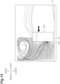
- FIG. 12 is a simulation result illustrating a flow of air around the active energy irradiation device 101.
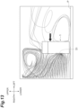
- FIG. 13 is a simulation result illustrating a flow of air around the active energy irradiation device 1.
- the printed matter P is conveyed in the left-right direction, and the active energy irradiation device 1 and 101 move in a left direction in the drawings above the printed matter P. Lines in the drawings represent the flow of the surrounding air.
- air containing foreign substances such as ink mist present around the device can be efficiently guided to the first opening 5 by the skirt portion 110.
- the ink mist can be guided to the first opening 5 by the skirt portion 110 to increase a collection rate of the ink mist. A possibility that the ink mist adheres to the printed matter P can be reduced, and the ink mist can be efficiently collected.
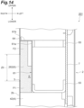
- FIG. 14 is an enlarged cross-sectional view illustrating a part of an active energy irradiation device 201 according to a second modification.
- the active energy irradiation device 201 according to the second modification is different from the active energy irradiation device 1 (see FIG. 3 ) in that the air introduction unit 6 includes a filter 262.
- the filter 262 includes a second filter portion F2.
- the second filter portion F2 is provided on an upper side (at least a side opposite to the heat sink 4 side) of the filter 262.
- the second filter portion F2 is thinner than the first filter portion F1.
- the second filter portion F2 is provided at a portion of the filter 262 from an upper end to a position from a center to an upper center in the up-down direction of the filter exposure region Z0.
- the second filter portion F2 has a constant thickness thinner than the thickness of the first filter portion F1.
- a side plate 61a side of the second filter portion F2 is not in contact with the side plate 61a, and a gap is formed between the second filter portion F2 and the side plate 61a. That is, a step is formed on the side plate 61a side of the filter 262.
- the filter 262 includes the second filter portion F2.
- the second filter portion F2 is thin, a passage path of the air in the filter 262 can be shortened, and thus, the resistance loss of the air can be reduced. It is possible to further suppress a decrease in a flow rate of air accompanying the increase in the use time, and it is possible to further suppress an increase in the temperature of the irradiation unit 3 accompanying the increase in the use time. It is possible to specifically realize the reduction of the resistance loss of the air in a case where the air passes through the upper side of the filter 262.
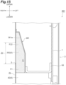
- FIG. 15 is an enlarged cross-sectional view illustrating a part of an active energy irradiation device 301 according to a third modification.
- the active energy irradiation device 301 according to the third modification is different from the active energy irradiation device 1 (see FIG. 3 ) in that the air introduction unit 6 includes a filter separator 361 and a filter 362.
- the filter separator 361 has a side plate 361a.
- the side plate 361a is inclined such that an upper portion approaches the side wall 2b toward an upper side from a center or a position closer to an upper center in the up-down direction.
- the filter 362 includes a second filter portion F22.
- the second filter portion F22 is provided on an upper side of the filter 362.
- the second filter portion F22 is thinner than the first filter portion F1.
- a thickness of the second filter portion F22 thinner than the first filter portion F1 may be an average thickness or a minimum thickness of the second filter portion F22.
- the second filter portion F22 is provided at a portion of the filter 362 from an upper end to a position from a center to an upper center in the up-down direction of the filter exposure region Z0.
- the second filter portion F22 is configured such that a thickness in the left-right direction becomes thinner toward an upper side. Similarly to the side plate 361a, the side plate 361a side of the second filter portion F22 is inclined to approach the side wall 2b toward an upper side. The side plate 361a side of the second filter portion F22 comes into contact with the side plate 361a without a gap.
- the active energy irradiation device 301 when the air mainly passes through the second filter portion F22 (when the clogging of the filter exposure region Z0 transitions upward due to an increase in a use time of the device), since the second filter portion F22 is thin, the passage path of the air in the filter 362 can be shortened, and thus, the resistance loss of the air can be reduced. It is possible to further suppress a decrease in a flow rate of air accompanying the increase in the use time, and it is possible to further suppress an increase in the temperature of the irradiation unit 3 accompanying the increase in the use time. It is possible to specifically realize the reduction of the resistance loss of the air in a case where the air passes through the upper side of the filter 362.
- FIG. 16 is an enlarged cross-sectional view illustrating a part of an active energy irradiation device 401 according to a fourth modification.
- the active energy irradiation device 401 according to the fourth modification is different from the active energy irradiation device 1 (see FIG. 3 ) in that the air introduction unit 6 includes a filter 462.
- the filter 462 includes a plurality of layers.
- the filter 462 includes a first filter layer 462x and a second filter layer 462y.
- the first filter layer 462x has a density higher (grain finer) than the second filter layer 462y.
- the second filter layer 462y has a density lower (grain coarser) than the first filter layer 462x.
- the active energy irradiation device 401 in the air introduction unit 6, the foreign substances can be actively collected (caught) by the first filter layer 462x having a high density, and the resistance loss can be suppressed by the second filter layer 462y having a low density. As a result, a distribution amount of the air introduction unit 6 can be increased.
- the density of each of the first filter layer 462x and the second filter layer 462y in the filter 462 is changed, and thus, the foreign substance collection performance and the resistance loss of the air in the filter 462 can be adjusted.
- the filter 462 is not limited to a structure of two layers, and may have a structure of three or more layers.
- the density (roughness) of each of the plurality of layers of the filter 462 is not particularly limited, and may be appropriately set in accordance with, for example, required performance.
- FIG. 17 is a perspective view illustrating an active energy irradiation device 501 according to a fifth modification. As illustrated in FIG. 16 , the active energy irradiation device 501 according to the fifth modification is different from the active energy irradiation device 1 (see FIG. 3 ) in that a filter cover 510 is provided.
- the filter cover 510 has a rectangular flat plate shape whose thickness direction is the left-right direction.
- the filter cover 510 comes into contact with the side wall 2b of the housing 2 without a gap to cover the first opening 5.
- the filter cover 510 is fixed to the side wall 2b with, for example, a screw.
- a plurality of long holes 510h that are long in the up-down direction and penetrate in the left-right direction are formed to be arranged at a predetermined interval in the front-rear direction.
- a width of each of the long holes 510h in the front-rear direction is smaller than a width of the small opening 51 of the first opening 5 in the front-rear direction.
- the filter cover 510 exposes the filter exposure region Z0 from the plurality of long holes 510h while covering the filter exposure region Z0 of the filter 62.
- a plurality of round holes, hexagonal holes, square holes, and meshes may be formed in the filter cover 510.
- the filter 62 can be protected by the filter cover 510.
- the filter cover 510 can prevent the filter 62 from easily escaping from the housing 2 via the first opening 5.
- the side plate (partition) 61a of the filter separator 61 is fixed and supported via the stay 63 (see FIG. 2 ), an aspect of fixing and supporting the filter separator 61 is not particularly limited.
- the side plate 61a of the filter separator 61 may be fixed to and supported by the driver board 7 via a columnar spacer 163.
- the active energy ray is not particularly limited, and may be an electron beam.
- the active energy irradiation device can be used as a device that irradiates the electron beam.
Landscapes
- Engineering & Computer Science (AREA)
- Health & Medical Sciences (AREA)
- Toxicology (AREA)
- General Health & Medical Sciences (AREA)
- General Engineering & Computer Science (AREA)
- Mechanical Engineering (AREA)
- Microbiology (AREA)
- Life Sciences & Earth Sciences (AREA)
- Textile Engineering (AREA)
- Cooling Or The Like Of Electrical Apparatus (AREA)
- Accessory Devices And Overall Control Thereof (AREA)
- Ink Jet (AREA)
- Physical Or Chemical Processes And Apparatus (AREA)
Abstract
Description
- The present disclosure relates to an active energy irradiation device and an inkjet printer.
- As a technique related to an active energy irradiation device, for example,
Patent Literature 1 describes a light irradiation device including a housing and a light source (irradiation unit) disposed in the housing. In the light irradiation device described inPatent Literature 1, an intake port through which air is sucked from an outside is provided in the housing, and the light source is cooled by the air flowing into the housing via a suction port. - Patent Literature 1:
Japanese Unexamined Patent Publication No. 2005-103845 - Foreign substances such as ink mist are floating in a device such as an injector printer in which the above-described active energy irradiation device is disposed. Thus, in the above-described active energy irradiation device, in order to suppress the entry of the foreign substances into the housing, a filter that collects foreign substances contained in the air flowing into the housing may be attached. However, in this case, clogging of the filter progresses as a use time of the device increases, a flow rate of the air flowing into the housing decreases. Thus, there is a possibility that a temperature of the irradiation unit rises (cooling is insufficient).
- An object of the present disclosure is to provide an active energy irradiation device and an inkjet printer capable of suppressing an increase in a temperature of an irradiation unit accompanying an increase in a use time.
- An active energy irradiation device according to one aspect of the present disclosure includes a housing, an irradiation unit that is disposed in the housing, and is configured to irradiate active energy rays, a heat conduction member that is disposed in the housing, and is thermally connected to the irradiation unit, a first opening that is provided at the housing, and an air introduction unit that deflects air flowing into the housing along a first direction via the first opening to a second direction intersecting the first direction to introduce the air to the heat conduction member. The air introduction unit includes a partition that is provided to face the first opening in the housing, and a filter that is provided between the first opening and the partition, and collects foreign substances contained in the air, and the filter includes a first filter portion that is provided on the heat conduction member side to come into contact with the partition without being exposed from the first opening as viewed from the first direction.
- In the active energy irradiation device, the air is introduced into the heat conduction member by the air introduction unit, the heat conduction member is cooled by the air, and the irradiation unit is cooled. In the air introduction unit, the foreign substances contained in the air are collected and removed by the filter including the first filter portion. Here, in the air introduction unit, the air flowing into the housing along the first direction via the first opening is deflected in the second direction intersecting the first direction and is introduced into the heat conduction member. As a result, a portion through which air easily passes on the deflected second direction side can be formed in a region (hereinafter, also referred to as a "filter exposure region") exposed from the first opening of the filter. In addition, since formation of a space between the filter and the partition can be suppressed by the presence of the first filter portion, a difference in a resistance loss of the air can be easily formed, and a portion through which air easily passes can be reliably formed in the filter exposure region. Accordingly, at the beginning of use of the device, the air flowing into the housing via the first opening does not uniformly pass through the entire filter exposure region, but mainly passes through a part thereof. When the clogging of the part of the filter progresses, a region through which air mainly passes transitions to another part of the filter exposure region, and this transition is repeated with the increase in the use time of the device. Consequently, even when the use time of the device increases, it is easy to secure a region where clogging has not progressed yet in the filter in the filter exposure region, and it is easy to secure a distribution amount of the air introduction unit similar to a distribution amount at the beginning of use. As a result, it is possible to suppress the increase in the temperature of the irradiation unit due to the increase in the use time.
- In the active energy irradiation device according to one aspect of the present disclosure, an entire region of the filter on the partition side comes into contact with the partition. In this case, the filter can be effectively supported by the partition.
- In the active energy irradiation device according to one aspect of the present disclosure, the filter may include a second filter portion that is provided on at least a side opposite to the heat conduction member side, and has a thickness in the first direction thinner than the first filter portion. In a case where the air is introduced into the heat conduction member through the side opposite to the heat conduction member in the filter, a passage path thereof becomes long, and a resistance loss is likely to increase. In this regard, according to one aspect of the present disclosure, in a case where the air passes through the side opposite to the heat conduction member side of the filter, since the filter includes the second filter portion, the passage path of the filter can be shortened, and the resistance loss of the air can be reduced.
- In the active energy irradiation device according to one aspect of the present disclosure, the second filter portion may be configured such that the thickness in the first direction becomes thinner toward the side opposite to the heat conduction member side. With such a configuration, it is possible to specifically realize the reduction of the resistance loss of the air in a case where the air passes through the opposite side of the heat conduction member side of the filter.
- In the active energy irradiation device according to one aspect of the present disclosure, the second filter portion may have a constant thickness thinner than the first filter portion. With such a configuration, it is possible to specifically realize the reduction of the resistance loss of the air in a case where the air passes through the opposite side of the heat conduction member side of the filter.
- The active energy irradiation device according to one aspect of the present disclosure may include a skirt portion that is disposed on the irradiation unit side from the first opening on an outer surface of the housing, and is provided to protrude in the first direction. In this case, the air containing the foreign substances such as ink mist present around the device can be efficiently guided to the first opening by the skirt portion.
- In the active energy irradiation device according to one aspect of the present disclosure, the filter may include a plurality of layers. In this case, for example, a density of each of the plurality of layers in the filter is changed, and thus, collection performance of the foreign substances, the resistance loss of the air, and the like in the filter can be adjusted.
- The active energy irradiation device according to one aspect of the present disclosure may include a second opening that is provided in the housing, and causes the air having passed through the heat conduction member to flow out of the housing. In this case, the air having cooled the heat conduction member can flow out of the housing via the second opening.
- In the active energy irradiation device according to one aspect of the present disclosure, the heat conduction member may be a heat sink. In this case, the irradiation unit can be cooled by using the heat sink as the heat conduction member.
- In the active energy irradiation device according to one aspect of the present disclosure, the irradiation unit may include a plurality of ultraviolet LEDs. In this case, ultraviolet rays can be irradiated as active energy.
- In the active energy irradiation device according to one aspect of the present disclosure, the filter may come into contact with the heat conduction member. In this case, the filter can be effectively supported by the heat conduction member.
- In the active energy irradiation device according to one aspect of the present disclosure, the first filter portion may be provided to cover a flow path of the air in the air introduction unit. In this case, the foreign substances contained in the air can be more reliably collected by the first filter portion.
- In the active energy irradiation device according to one aspect of the present disclosure, a mark indicating that a clogging ratio of the filter is a predetermined ratio may be provided to at least any one of the filter and the housing. In this case, it is possible to easily confirm whether or not clogging has transitioned to a predetermined ratio in the filter by referring to the mark.
- In the active energy irradiation device according to one aspect of the present disclosure, the active energy irradiation device may irradiate a printed matter to which ink adheres, as an object to be irradiated, and the filter is a filter of a color different from a color of the ink. In this case, a state of transition of clogging in the filter becomes clear, and it is possible to easily confirm a degree of clogging.
- An inkjet printer according to another aspect of the present disclosure includes the active energy irradiation device. In this inkjet printer, the above effect, that is, the effect of suppressing the increase in the temperature of the irradiation unit with the increase in the use time can also be obtained by the active energy irradiation device.
- According to the present disclosure, it is possible to provide the active energy irradiation device and the inkjet printer capable of suppressing the increase in the temperature of the irradiation unit accompanying the increase in the use time.
-
-
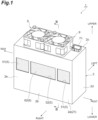
FIG. 1 is a perspective view illustrating an active energy irradiation device according to an embodiment. -
FIG. 2 is a perspective view illustrating an inside of a housing of the active energy irradiation device according to the embodiment. -
FIG. 3 is a cross-sectional view taken along line III-III ofFIG. 1 . -
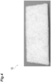
FIG. 4 is a photograph illustrating a filter according to the embodiment. -
FIG. 5 is a cross-sectional view illustrating a flow of air in the housing at the beginning of use in the active energy irradiation device according to the embodiment. -
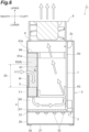
FIG. 6 is a cross-sectional view illustrating a flow of the air in the housing when a use time in the active energy irradiation device according to the embodiment increases. -
FIGS. 7(a) to 7(d) are diagrams illustrating a part of the filter in the active energy irradiation device according to the embodiment.FIG. 7(e) is a graph showing a relationship between clogging of the filter and the temperature of the irradiation unit in the active energy irradiation device according to the embodiment. -
FIGS. 8(a) to 8(d) are diagrams illustrating a part of a filter in an active energy irradiation device according to a comparative example.FIG. 8(e) is a graph showing a relationship between clogging of the filter and a temperature of an irradiation unit in the active energy irradiation device according to the comparative example. -
FIG. 9 is a schematic configuration diagram illustrating an inkjet printer including the active energy irradiation device according to the embodiment. -
FIG. 10 is a perspective view illustrating an active energy irradiation device according to a first modification. -
FIG. 11 is a front view illustrating the active energy irradiation device according to the first modification. -
FIG. 12 is a simulation result showing a flow of air around the active energy irradiation device according to the first modification. -
FIG. 13 is a simulation result showing a flow of air around the active energy irradiation device according to the embodiment. -
FIG. 14 is an enlarged cross-sectional view illustrating a part of an active energy irradiation device according to a second modification. -
FIG. 15 is an enlarged cross-sectional view illustrating a part of an active energy irradiation device according to a third modification. -
FIG. 16 is an enlarged cross-sectional view illustrating a part of an active energy irradiation device according to a fourth modification. -
FIG. 17 is a perspective view illustrating an active energy irradiation device according to a fifth modification. -
FIG. 18 is a perspective view illustrating an active energy irradiation device according to a sixth modification. - Hereinafter, an embodiment will be described in detail with reference to the drawings. The same or corresponding portions in the drawings are denoted with the same reference signs, and repetitive descriptions will be omitted.
- An active
energy irradiation device 1 illustrated inFIG. 1 is, for example, an LED light source (light irradiation device) for printing. The activeenergy irradiation device 1 irradiates an object to be irradiated with ultraviolet rays (active energy rays) to perform ink drying and the like of the object to be irradiated. Examples of the object to be irradiated include a printed matter to which a photocurable ink adheres. As illustrated inFIGS. 1 ,2 , and3 , the activeenergy irradiation device 1 includes ahousing 2, anirradiation unit 3, a heat sink (heat conduction member) 4, afirst opening 5, anair introduction unit 6, adriver board 7, asecond opening 8, andfans 9. - In the following description, for the sake of convenience in description, a direction in which the active
energy irradiation device 1 emits ultraviolet rays is referred to as "downward", and an opposite side is referred to as "upward". A direction orthogonal to the "up-down direction" is referred to as a "left-right direction", and a direction orthogonal to the "up-down direction" and the "left-right direction" is referred to as a "front-rear direction". - The
housing 2 has a rectangular box shape. Thehousing 2 is made of metal. Thehousing 2 accommodates theirradiation unit 3, theheat sink 4, theair introduction unit 6, and thedriver board 7 therein. Alight irradiation window 21 made of a glass plate is provided in alower wall 2a of thehousing 2. - The
irradiation unit 3 is disposed in thehousing 2. Theirradiation unit 3 irradiates ultraviolet rays as active energy rays. Theirradiation unit 3 includes a rectangular plate-shapedsubstrate 31 constituting a predetermined circuit, and ultraviolet light emitting diodes (LEDs) 32 which are light emitting elements arranged side by side at a predetermined pitch in the front-rear direction and the left-right direction on thesubstrate 31. Theirradiation unit 3 is disposed at a lower end inside thehousing 2 such that a thickness direction of thesubstrate 31 is the up-down direction. The object to be irradiated is irradiated with the ultraviolet rays emitted from theultraviolet LED 32 of theirradiation unit 3 via thelight irradiation window 21 of thehousing 2. - The
heat sink 4 is disposed in thehousing 2. Theheat sink 4 is thermally connected to theirradiation unit 3. Theheat sink 4 is an air-cooling type heat dissipation member that dissipates heat by heat exchange with air. The air constitutes a heating medium (refrigerant or cooling air) for cooling theirradiation unit 3. Theheat sink 4 includes abase plate 41 and a plurality ofheat dissipation fins 42. Thebase plate 41 has a rectangular plate shape whose thickness direction is the up-down direction. Lower surfaces of thebase plate 41 come into contact with thesubstrate 31 of theirradiation unit 3. Theheat dissipation fin 42 has a flat plate shape whose thickness direction is the front-rear direction. Theheat dissipation fins 42 are erected on an upper surface of thebase plate 41. Theheat dissipation fins 42 are arranged to be stacked with a gap in the front-rear direction. Theheat sink 4 is fixed to thehousing 2 by, for example, a screw or the like. - The
first opening 5 is an opening provided in aside wall 2b of thehousing 2. Here, thefirst opening 5 has a rectangular shape, and is formed in a central portion of theside wall 2b in the up-down direction. Thefirst opening 5 constitutes an intake port for taking in air outside thehousing 2 into thehousing 2. Thefirst opening 5 is opened in the left-right direction in theside wall 2b and communicates the inside and outside of thehousing 2. Thefirst opening 5 includessmall openings 51 formed at one end and the other end of theside wall 2b in the front-rear direction, and alarge opening 52 formed between thesmall openings 51. - The
air introduction unit 6 is disposed in thehousing 2. Theair introduction unit 6 deflects air flowing into thehousing 2 along the left-right direction (first direction) via thefirst opening 5 downward toward the heat sink 4 (second direction intersecting the first direction), and introduces the air into theheat sink 4. Theair introduction unit 6 connects thefirst opening 5 and theheat sink 4. Theair introduction unit 6 is disposed on thefirst opening 5 side in thehousing 2. - The
driver board 7 is disposed in thehousing 2. Thedriver board 7 is a driving electric circuit substrate for driving the activeenergy irradiation device 1. Thedriver board 7 is disposed on a side opposite to thefirst opening 5 side in thehousing 2 with the left-right direction as the thickness direction. Thedriver board 7 is fixed to thehousing 2 with a screw or the like via, for example, a spacer (not illustrated) or the like. A lower portion of thedriver board 7 is electrically connected to thesubstrate 31 of theirradiation unit 3. A power supply and signal input andoutput connector 71 is electrically connected to an upper portion of thedriver board 7. Theconnector 71 is provided to protrude upward from a front end of anupper wall 2c of thehousing 2. - The
second opening 8 is an opening provided in theupper wall 2c of thehousing 2. Thesecond opening 8 constitutes an exhaust port for exhausting air in thehousing 2 to the outside of thehousing 2. Thesecond opening 8 is opened in theupper wall 2c in the up-down direction and communicates the inside and the outside of thehousing 2. Thefans 9 are fixed on thesecond opening 8 in theupper wall 2c of thehousing 2. Thefans 9 pressure-feed air sucked from below (inside the housing 2) to above (outside the housing 2). Here, a pair offans 9 is provided to be arranged in the front-rear direction. For example, an axial fan is used as thefan 9. Only onefan 9 may be provided, or three or more fans may be provided side by side. - In the present embodiment, the
air introduction unit 6 includes afilter separator 61 and afilter 62. - The
filter separator 61 defines (partitions) a space R positioned on thefirst opening 5 side and communicating with the outside via thefirst opening 5 in thehousing 2. Thefilter separator 61 is fixed in thehousing 2. Thefilter separator 61 includes a side plate (partition) 61a and anupper plate 61b. Theside plate 61a has a rectangular flat plate shape whose thickness direction is the left-right direction. Theside plate 61a is provided to face thefirst opening 5 in thehousing 2. Theside plate 61a is disposed away from theside wall 2b of thehousing 2 by a predetermined distance. An upper end of theside plate 61a is positioned above thefirst opening 5. A lower end of theside plate 61a is positioned below thefirst opening 5 and is close to upper surfaces of theheat dissipation fins 42 of theheat sink 4. A front end of theside plate 61a comes into contact with afront wall 2d of thehousing 2 without a gap. A rear end of theside plate 61a comes into contact with arear wall 2e of thehousing 2 without a gap. Theside plate 61a is fixed to and supported by thedriver board 7 via, for example, astay 63. Theupper plate 61b has a rectangular flat plate shape whose thickness direction is the up-down direction. One end side of theupper plate 61b in the left-right direction is provided to be continuous with the upper end of theside plate 61a. The other end side of theupper plate 61b in the left-right direction comes into contact with theside wall 2b of thehousing 2 without a gap. Theupper plate 61b is fixed to theside wall 2b of thehousing 2 via aflange 64 with a screw or the like. - The
filter 62 collects foreign substances contained in the air flowing into thehousing 2. Examples of the foreign substances include ink mist, dirt, and dust. Thefilter 62 has, for example, a rectangular plate shape with a thickness of 10 mm (seeFIG. 4 ). Thefilter 62 is made of, for example, urethane. Thefilter 62 is provided between thefirst opening 5 and theside plate 61a of thefilter separator 61. Thefilter 62 is disposed in the space R. Thefilter 62 is exposed to the outside via thefirst opening 5. - The entire region of the
filter 62 on theside plate 61a side (one end side in the left-right direction) comes into contact with theside plate 61a without a gap. Thefirst opening 5 side (the other end side in the left-right direction) of thefilter 62 comes into contact with theside wall 2b without a gap except for a region exposed from the first opening 5 (hereinafter, also referred to as a "filter exposure region Z0"). The entire upper region of thefilter 62 comes into contact with theupper plate 61b of thefilter separator 61 without a gap. The entire lower region of thefilter 62 comes into contact with the upper surfaces of theheat dissipation fins 42 of theheat sink 4 without a gap. Thefilter 62 is supported or held by thefilter separator 61, theheat sink 4, and thehousing 2. Thefilter 62 is not bonded to thefilter separator 61, theheat sink 4, and thehousing 2 with an adhesive or the like. Thefilter 62 is pushed into the space R and comes into contact with thefilter separator 61, theheat sink 4, and thehousing 2. Such afilter 62 can be easily replaced by entering the space R via thefirst opening 5 and exiting the space R. - The
filter 62 includes a first filter portion F1. The first filter portion F1 has a function or a role as a portion (that is, filter performance buffer region) that compensates for foreign substance collecting performance of thefilter 62. The first filter portion F1 is provided on a lower side (in other words, a downstream side of the air) of thefilter 62 on theheat sink 4 side. The first filter portion F1 is a portion that is not exposed from thefirst opening 5 and is covered with theside wall 2b of thehousing 2 as viewed from the left-right direction. The first filter portion F1 is a portion having a volume of a predetermined amount or more. The first filter portion F1 is a portion coming into contact with theside plate 61a of thefilter separator 61. The first filter portion F1 has a thickness enough to come into contact with theside plate 61a. The first filter portion F1 is provided to close a flow path of air in theair introduction unit 6, and comes into contact with an inner surface of thehousing 2 and theside plate 61a without a gap. - In the active
energy irradiation device 1 having the above configuration, as illustrated inFIG. 5 , the air flowing into thehousing 2 from thefirst opening 5 is introduced to the other end side in the left-right direction between theheat dissipation fins 42 of theheat sink 4 by theair introduction unit 6. In theair introduction unit 6, the foreign substances such as ink mist contained in the air are collected and removed by thefilter 62. In particular, the first filter portion F1 of thefilter 62 reliably collects the foreign substances of the air. Then, the air flows between theheat dissipation fins 42 toward one end side in the left-right direction, and thus, theheat sink 4 is cooled and theirradiation unit 3 is cooled. Thereafter, the air flows upward from between one end in the left-right direction between theheat dissipation fins 42 and thedriver board 7, and is exhausted to the outside of thehousing 2 from thesecond opening 8 by thefans 9. - Here, in the
air introduction unit 6, the air flowing into thehousing 2 along the left-right direction via thefirst opening 5 is deflected in a lower direction (a flow is bent by 90 degrees) and is introduced into theheat sink 4. As a result, in the filter exposure region Z0 of thefilter 62, a portion through which air easily passes can be formed on a lower side where the air is deflected. Specifically, a portion through which air easily passes can be formed on a lower side of the filter exposure region Z0, and a portion through which air hardly passes can be formed on an upper side of the filter exposure region Z0. In other words, thefilter 62 can be formed such that air easily passes as the air moves to the lower side of the filter exposure region Z0. - In addition, since formation of a space (gap) between the
filter 62 and thefilter separator 61 can be suppressed by the presence of the first filter portion F1, a difference in a resistance loss of the air in thefilter 62 can be easily formed, and a portion through which air easily passes can be reliably formed in the filter exposure region Z0. When there is a space between thefilter 62 and thefilter separator 61, a difference in the resistance loss in thefilter 62 is likely to be reduced, and it is difficult to form a portion through which air easily passes in the filter exposure region Z0. - Accordingly, at the beginning of use of the device, the air flowing into the
housing 2 via thefirst opening 5 does not uniformly pass through the entire filter exposure region Z0, but mainly passes through a lower portion (part) of the filter exposure region Z0. Then, as illustrated inFIG. 6 , when the use time of the device increases and clogging M progresses in the lower portion of the filter exposure region Z0, a region through which the air mainly passes transitions to the upper portion (other part) of the filter exposure region Z0. Such a transition is repeated as the use time of the device increases until the entire filter exposure region Z0 is clogged. - Consequently, according to the active
energy irradiation device 1, even when the use time of the apparatus increases, as compared with a case where theentire filter 62 is uniformly clogged, it is easy to secure a region where the clogging M has not yet progressed in the filter exposure region Z0 of thefilter 62, and it is easy to secure a distribution amount of theair introduction unit 6 similar to the distribution amount at the beginning of use. As a result, it is possible to suppress a decrease in a flow rate of air accompanying an increase in the use time, and it is possible to suppress an increase in a temperature of theirradiation unit 3 accompanying the increase in the use time. Even though the use time increases, for example, it is possible to suppress the decrease in the flow rate of air and the increase in the temperature of theirradiation unit 3 until the filter exposure region Z0 is completely clogged as a whole. The output of the activeenergy irradiation device 1 can be stabilized for a long time. It is possible to lengthen a time during which performance can be maintained before the replacement of thefilter 62. - In the active
energy irradiation device 1, the entire region of thefilter 62 on theside plate 61a side of thefilter separator 61 comes into contact with theside plate 61a. In this case, thefilter 62 can be effectively supported by theside plate 61a. - The active
energy irradiation device 1 includes thesecond opening 8 that is provided in thehousing 2 and allows the air having passed through theheat sink 4 to flow out of thehousing 2. In this case, the air having cooled theheat sink 4 can flow out of thehousing 2 via thesecond opening 8. - The active
energy irradiation device 1 includes theheat sink 4 as the heat conduction member. In this case, theirradiation unit 3 can be cooled by using theheat sink 4 as the heat conduction member. - In the active
energy irradiation device 1, theirradiation unit 3 includes the plurality ofultraviolet LEDs 32. In this case, theirradiation unit 3 can irradiate the ultraviolet rays as the active energy. - In the active
energy irradiation device 1, thefilter 62 comes into contact with theheat dissipation fins 42 of theheat sink 4. In this case, thefilter 62 can be effectively supported by theheat dissipation fins 42 of theheat sink 4. - In the active
energy irradiation device 1, the first filter portion F1 of thefilter 62 is provided to close the flow path of the air in theair introduction unit 6. In this case, the foreign substance collecting performance of thefilter 62 can be reliably compensated by the first filter portion F1, and the foreign substances contained in the air can be more reliably collected. - In the active
energy irradiation device 1, thefirst opening 5 has a rectangular shape with a large aperture ratio. In this case, the filter exposure region Z0 can be increased, and the convenience of replacement of thefilter 62 can be enhanced. In addition, manufacturing cost can be suppressed. -
FIGS. 7(a) to 7(d) are diagrams illustrating a part of thefilter 62 in the activeenergy irradiation device 1.FIG. 7(e) is a graph showing a relationship between the clogging of thefilter 62 and the temperature of theirradiation unit 3 in the activeenergy irradiation device 1. InFIGS. 7(a) to 7(d) , the use time of the device increases in this order. That is, in the present embodiment, as the use time increases, the filter exposure region Z0 of thefilter 62 transitions to states illustrated inFIGS. 7(a) to 7(d) in this order. The up-down direction in each drawing corresponds to the up-down direction inFIG. 5 . InFIG. 7(e) , the vertical axis represents the temperature (°C) of theirradiation unit 3, and the horizontal axis represents the ratio of clogging of thefilter 62. A ratio of clogging corresponds to a degree of progress of clogging and corresponds to the use time of the device. The ratio of clogging indicates that clogging progresses as a value thereof increases, and does not depend on a location where clogging has occurred. A ratio of clogging of 50% means that thefilter 62 is half clogged, and a ratio of clogging of 100% means that thefilter 62 is completely clogged. - As illustrated in
FIGS. 7(a) to 7(d) , in the present embodiment, air mainly passes through the lower portion of the filter exposure region Z0 at the beginning of use, and the clogging M occurs therein. As the use time of the device increases, the region through which the air mainly passes transitions to the upper portion, and the clogging M also transitions to the upper portion. As a result, as illustrated inFIG. 7(e) , for example, until the ratio of clogging of thefilter 62reaches 70% to 80% with the increase in the use time, it is possible to suppress the increase in the temperature of theirradiation unit 3, and it is possible to maintain the temperature of theirradiation unit 3 at 70°C or lower. - A mark RL (see
FIG. 7(a) and the like) indicating that the ratio of the clogging M of thefilter 62 is a predetermined ratio may be provided to at least one of thefilter 62 and thehousing 2. In this case, it is possible to easily confirm whether or not the clogging M has transitioned to a predetermined ratio in thefilter 62 by referring to the mark RL. In addition, for example, since the clogging M transitions to the upper portion, an instruction about a position corresponding to a filter replacement time (such as a position where the ratio of the clogging M becomes 70% to 80% (predetermined ratio)) is given with the mark RL. Accordingly, it is possible to indicate that it is the filter replacement time when the clogging M transitions to the instructed position, and it is possible to encourage the replacement of thefilter 62. The mark RL is not particularly limited, and may be a line, a dot, or other marks. The position where the mark RL is provided is not particularly limited, and may be thefilter 62, or alternatively or additionally, may be a periphery of thefirst opening 5 where thefilter 62 is exposed in theside wall 2b of thehousing 2. The predetermined ratio is not particularly limited, and may be various ratios. - In addition, the
filter 62 may be a filter of a color (for example, a white or yellow ink is used for black ink, and a black ink is used for white ink) different from a printing color (color of the ink of the object to be irradiated as the printed matter). In this case, a state of transition of the clogging M to the upper portion becomes clear, and it is possible to easily confirm a degree of the clogging M. -
FIGS. 8(a) to 8(d) are diagrams illustrating a part of afilter 62 in an active energy irradiation device according to a comparative example.FIG. 8(e) is a graph showing a relationship between the clogging of thefilter 62 and the temperature of theirradiation unit 3 in the active energy irradiation device according to the comparative example. The active energy irradiation device according to the comparative example is different from the activeenergy irradiation device 1 in that theentire filter 62 is uniformly clogged as the use time of the device increases. InFIGS. 8(a) to 8(d) , the use time of the device increases in this order. That is, as the use time increases, thefilter 62 transitions to states illustrated inFIGS. 8(a) to 8(d) in this order. The up-down direction in each drawing corresponds to the up-down direction inFIG. 5 . InFIG. 8(e) , a vertical axis represents the temperature (°C) of theirradiation unit 3, and a horizontal axis represents the clogging ratio of thefilter 62. - As illustrated in
FIGS. 8(a) to 8(d) , in the active energy irradiation device according to the comparative example, air is uniformly clogged in theentire filter 62 as the use time of the device increases from the beginning of use. As a result, as illustrated inFIG. 8(e) , for example, it can be seen that the ratio of clogging of thefilter 62 gradually increases with the increase in the use time, and the temperature of theirradiation unit 3 reaches 70°C at a point in time when the ratio of clogging is 50%. -
FIG. 9 is a schematic configuration diagram illustrating aninkjet printer 100 including the activeenergy irradiation device 1. As illustrated inFIG. 9 , the activeenergy irradiation device 1 can be mounted on theinkjet printer 100. Theinkjet printer 100 further includes acarriage 10. Thecarriage 10 includes a plurality of recording heads. The plurality of recording heads eject a photocurable ink toward a printed matter P conveyed in the left-right direction below thecarriage 10. Thecarriage 10 and the activeenergy irradiation device 1 are connected in the left-right direction. In theinkjet printer 100, thecarriage 10 and the activeenergy irradiation device 1 are scanned (moved) along the left-right direction at the time of printing. Theinkjet printer 100 may include a plurality of activeenergy irradiation devices 1. - In such an
inkjet printer 100, the above effect, that is, the effect of suppressing the increase in the temperature of the irradiation unit with the increase in the use time can be obtained by the activeenergy irradiation device 1. - An aspect of the present disclosure is not limited to the above embodiment.
-
FIG. 10 is a perspective view illustrating an activeenergy irradiation device 101 according to a first modification.FIG. 11 is a front view illustrating the activeenergy irradiation device 101 according to the first modification. As illustrated inFIGS. 10 and11 , the activeenergy irradiation device 101 according to the first modification is different from the active energy irradiation device 1 (seeFIG. 1 ) in that askirt portion 110 is provided. - The
skirt portion 110 is disposed below the first opening 5 (on theirradiation unit 3 side) on an outer surface of theside wall 2b of thehousing 2. Theskirt portion 110 is provided to protrude outward in the left-right direction from the outer surface of theside wall 2b. Theskirt portion 110 is disposed on the outer surface of theside wall 2b in a range from a position away downward from thefirst opening 5 by a predetermined length to a lower edge, and is fixed to theside wall 2b with a screw or the like. Theskirt portion 110 has aguide surface 110a as a curved surface smoothly continuing to the outer surface of theside wall 2b. - The
guide surface 110a has an arc shape as viewed from the front-rear direction. An upper end of theguide surface 110a is continuous with the outer surface of theside wall 2b, and a lower end of theguide surface 110a is away outward in the left-right direction from the outer surface of theside wall 2b. A lower surface of theskirt portion 110 is flush with an outer surface of thelower wall 2a of thehousing 2. A front surface of theskirt portion 110 is flush with an outer surface of thefront wall 2d of thehousing 2. A rear surface of theskirt portion 110 is flush with an outer surface of therear wall 2e of thehousing 2. Such askirt portion 110 may be a machined part, a sheet metal part, or a resin molded part. Instead of or in addition to the curved surface, theguide surface 110a of theskirt portion 110 may include a flat surface that is linear as viewed from the front-rear direction. For example, theguide surface 110a may include an inclined surface that is away from theside wall 2b toward a lower side. -
FIG. 12 is a simulation result illustrating a flow of air around the activeenergy irradiation device 101.FIG. 13 is a simulation result illustrating a flow of air around the activeenergy irradiation device 1. In the illustrated examples, the printed matter P is conveyed in the left-right direction, and the activeenergy irradiation device - As illustrated in
FIGS. 12 and13 , in the activeenergy irradiation device 101, air containing foreign substances such as ink mist present around the device can be efficiently guided to thefirst opening 5 by theskirt portion 110. The ink mist can be guided to thefirst opening 5 by theskirt portion 110 to increase a collection rate of the ink mist. A possibility that the ink mist adheres to the printed matter P can be reduced, and the ink mist can be efficiently collected. -
FIG. 14 is an enlarged cross-sectional view illustrating a part of an activeenergy irradiation device 201 according to a second modification. As illustrated inFIG. 14 , the activeenergy irradiation device 201 according to the second modification is different from the active energy irradiation device 1 (seeFIG. 3 ) in that theair introduction unit 6 includes afilter 262. - The
filter 262 includes a second filter portion F2. The second filter portion F2 is provided on an upper side (at least a side opposite to theheat sink 4 side) of thefilter 262. The second filter portion F2 is thinner than the first filter portion F1. The second filter portion F2 is provided at a portion of thefilter 262 from an upper end to a position from a center to an upper center in the up-down direction of the filter exposure region Z0. The second filter portion F2 has a constant thickness thinner than the thickness of the first filter portion F1. Aside plate 61a side of the second filter portion F2 is not in contact with theside plate 61a, and a gap is formed between the second filter portion F2 and theside plate 61a. That is, a step is formed on theside plate 61a side of thefilter 262. - In a case where air is introduced into the
heat sink 4 through a center or an upper side of the filter 62 (seeFIG. 3 ), a passage path thereof becomes long and the resistance loss is likely to increase as compared with a case where air is introduced into theheat sink 4 through a lower side of the filter 62 (seeFIG. 3 ). By doing this, when the clogging of the filter exposure region Z0 transitions upward from a lower portion as a use time of the device increases and the air mainly passes through the center or the upper side of the filter 62 (seeFIG. 3 ), there is a possibility that the resistance loss is likely to increase. - In this regard, in the active
energy irradiation device 201, thefilter 262 includes the second filter portion F2. As a result, when the air mainly passes through the second filter portion F2 (when the clogging of the filter exposure region Z0 transitions upward due to an increase in the use time of the device), since the second filter portion F2 is thin, a passage path of the air in thefilter 262 can be shortened, and thus, the resistance loss of the air can be reduced. It is possible to further suppress a decrease in a flow rate of air accompanying the increase in the use time, and it is possible to further suppress an increase in the temperature of theirradiation unit 3 accompanying the increase in the use time. It is possible to specifically realize the reduction of the resistance loss of the air in a case where the air passes through the upper side of thefilter 262. -
FIG. 15 is an enlarged cross-sectional view illustrating a part of an activeenergy irradiation device 301 according to a third modification. As illustrated inFIG. 15 , the activeenergy irradiation device 301 according to the third modification is different from the active energy irradiation device 1 (seeFIG. 3 ) in that theair introduction unit 6 includes afilter separator 361 and afilter 362. - The
filter separator 361 has aside plate 361a. Theside plate 361a is inclined such that an upper portion approaches theside wall 2b toward an upper side from a center or a position closer to an upper center in the up-down direction. Thefilter 362 includes a second filter portion F22. The second filter portion F22 is provided on an upper side of thefilter 362. The second filter portion F22 is thinner than the first filter portion F1. A thickness of the second filter portion F22 thinner than the first filter portion F1 may be an average thickness or a minimum thickness of the second filter portion F22. The second filter portion F22 is provided at a portion of thefilter 362 from an upper end to a position from a center to an upper center in the up-down direction of the filter exposure region Z0. The second filter portion F22 is configured such that a thickness in the left-right direction becomes thinner toward an upper side. Similarly to theside plate 361a, theside plate 361a side of the second filter portion F22 is inclined to approach theside wall 2b toward an upper side. Theside plate 361a side of the second filter portion F22 comes into contact with theside plate 361a without a gap. - Similarly to the active
energy irradiation device 201 according to the second modification, in the activeenergy irradiation device 301, when the air mainly passes through the second filter portion F22 (when the clogging of the filter exposure region Z0 transitions upward due to an increase in a use time of the device), since the second filter portion F22 is thin, the passage path of the air in thefilter 362 can be shortened, and thus, the resistance loss of the air can be reduced. It is possible to further suppress a decrease in a flow rate of air accompanying the increase in the use time, and it is possible to further suppress an increase in the temperature of theirradiation unit 3 accompanying the increase in the use time. It is possible to specifically realize the reduction of the resistance loss of the air in a case where the air passes through the upper side of thefilter 362. -
FIG. 16 is an enlarged cross-sectional view illustrating a part of an activeenergy irradiation device 401 according to a fourth modification. As illustrated inFIG. 16 , the activeenergy irradiation device 401 according to the fourth modification is different from the active energy irradiation device 1 (seeFIG. 3 ) in that theair introduction unit 6 includes afilter 462. - The
filter 462 includes a plurality of layers. Here, thefilter 462 includes a first filter layer 462x and a second filter layer 462y. The first filter layer 462x has a density higher (grain finer) than the second filter layer 462y. In other words, the second filter layer 462y has a density lower (grain coarser) than the first filter layer 462x. In the activeenergy irradiation device 401, in theair introduction unit 6, the foreign substances can be actively collected (caught) by the first filter layer 462x having a high density, and the resistance loss can be suppressed by the second filter layer 462y having a low density. As a result, a distribution amount of theair introduction unit 6 can be increased. - According to the active
energy irradiation device 401, for example, the density of each of the first filter layer 462x and the second filter layer 462y in thefilter 462 is changed, and thus, the foreign substance collection performance and the resistance loss of the air in thefilter 462 can be adjusted. Thefilter 462 is not limited to a structure of two layers, and may have a structure of three or more layers. The density (roughness) of each of the plurality of layers of thefilter 462 is not particularly limited, and may be appropriately set in accordance with, for example, required performance. -
FIG. 17 is a perspective view illustrating an activeenergy irradiation device 501 according to a fifth modification. As illustrated inFIG. 16 , the activeenergy irradiation device 501 according to the fifth modification is different from the active energy irradiation device 1 (seeFIG. 3 ) in that afilter cover 510 is provided. - The
filter cover 510 has a rectangular flat plate shape whose thickness direction is the left-right direction. Thefilter cover 510 comes into contact with theside wall 2b of thehousing 2 without a gap to cover thefirst opening 5. Thefilter cover 510 is fixed to theside wall 2b with, for example, a screw. In thefilter cover 510, a plurality oflong holes 510h that are long in the up-down direction and penetrate in the left-right direction are formed to be arranged at a predetermined interval in the front-rear direction. A width of each of thelong holes 510h in the front-rear direction is smaller than a width of thesmall opening 51 of thefirst opening 5 in the front-rear direction. Thefilter cover 510 exposes the filter exposure region Z0 from the plurality oflong holes 510h while covering the filter exposure region Z0 of thefilter 62. Instead of or in addition to thelong holes 510h, a plurality of round holes, hexagonal holes, square holes, and meshes may be formed in thefilter cover 510. - According to the active
energy irradiation device 501, thefilter 62 can be protected by thefilter cover 510. In addition, thefilter cover 510 can prevent thefilter 62 from easily escaping from thehousing 2 via thefirst opening 5. - In the above embodiment, although the side plate (partition) 61a of the
filter separator 61 is fixed and supported via the stay 63 (seeFIG. 2 ), an aspect of fixing and supporting thefilter separator 61 is not particularly limited. For example, as illustrated inFIG. 18 , theside plate 61a of thefilter separator 61 may be fixed to and supported by thedriver board 7 via acolumnar spacer 163. - In the above-described embodiment and modifications, although the
irradiation unit 3 irradiates the irradiation of the ultraviolet rays as the active energy rays, the active energy ray is not particularly limited, and may be an electron beam. In this case, the active energy irradiation device can be used as a device that irradiates the electron beam. - Various materials and shapes can be applied to each configuration in the above-described embodiment and modifications without being limited to the above-described materials and shapes. In addition, each configuration in the above-described embodiment and modifications can be arbitrarily applied to each configuration in other embodiments or modifications.
-
- 1, 101, 201, 301, 401, 501
- active energy irradiation device
- 2
- housing
- 3
- irradiation unit
- 4
- heat sink (heat conduction member)
- 5
- first opening
- 6
- air introduction unit
- 8
- second opening
- 32
- ultraviolet LED
- 61a, 361a
- side plate (partition)
- 62, 262, 362, 462
- filter
- 100
- inkjet printer
- 110
- skirt portion
- F1
- first filter portion
- F2, F22
- second filter portion
Claims (15)
- An active energy irradiation device comprising:a housing;an irradiation unit that is disposed in the housing, and is configured to irradiate active energy rays;a heat conduction member that is disposed in the housing, and is thermally connected to the irradiation unit;a first opening that is provided at the housing; andan air introduction unit that deflects air flowing into the housing along a first direction via the first opening to a second direction intersecting the first direction to introduce the air to the heat conduction member, whereinthe air introduction unit includesa partition that is provided to face the first opening in the housing, anda filter that is provided between the first opening and the partition, and collects foreign substances contained in the air, andthe filter includesa first filter portion that is provided on the heat conduction member side to come into contact with the partition without being exposed from the first opening as viewed from the first direction.
- The active energy irradiation device according to claim 1, wherein an entire region of the filter on the partition side comes into contact with the partition.
- The active energy irradiation device according to claim 1 or 2, wherein the filter includes a second filter portion that is provided on at least a side opposite to the heat conduction member side, and has a thickness in the first direction thinner than the first filter portion.
- The active energy irradiation device according to claim 3, wherein the second filter portion is configured such that the thickness in the first direction becomes thinner toward the side opposite to the heat conduction member side.
- The active energy irradiation device according to claim 3, wherein the second filter portion has a constant thickness thinner than the first filter portion.
- The active energy irradiation device according to any one of claims 1 to 5, further comprising: a skirt portion that is disposed on the irradiation unit side from the first opening on an outer surface of the housing, and is provided to protrude in the first direction.
- The active energy irradiation device according to any one of claims 1 to 6, wherein the filter includes a plurality of layers.
- The active energy irradiation device according to any one of claims 1 to 7, further comprising: a second opening that is provided in the housing, and causes the air having passed through the heat conduction member to flow out of the housing.
- The active energy irradiation device according to any one of claims 1 to 8, wherein the heat conduction member is a heat sink.
- The active energy irradiation device according to any one of claims 1 to 9, wherein the irradiation unit has a plurality of ultraviolet LEDs.
- The active energy irradiation device according to any one of claims 1 to 10, wherein the filter comes into contact with the heat conduction member.
- The active energy irradiation device according to any one of claims 1 to 11, wherein the first filter portion is provided to cover a flow path of the air in the air introduction unit.
- The active energy irradiation device according to any one of claims 1 to 12, wherein a mark indicating that a clogging ratio of the filter is a predetermined ratio is provided to at least any one of the filter and the housing.
- The active energy irradiation device according to any one of claims 1 to 13, whereinthe active energy irradiation device irradiates a printed matter to which ink adheres, as an object to be irradiated, andthe filter is a filter of a color different from a color of the ink.
- An inkjet printer comprising the active energy irradiation device according to any one of claims 1 to 14.
Applications Claiming Priority (2)
| Application Number | Priority Date | Filing Date | Title |
|---|---|---|---|
| JP2021136099A JP7105978B1 (en) | 2021-08-24 | 2021-08-24 | Active energy irradiation device and inkjet printer |
| PCT/JP2022/017191 WO2023026577A1 (en) | 2021-08-24 | 2022-04-06 | Active energy irradiation device and inkjet printer |
Publications (2)
| Publication Number | Publication Date |
|---|---|
| EP4338962A1 true EP4338962A1 (en) | 2024-03-20 |
| EP4338962A4 EP4338962A4 (en) | 2025-06-25 |
Family
ID=82556756
Family Applications (1)
| Application Number | Title | Priority Date | Filing Date |
|---|---|---|---|
| EP22860875.8A Pending EP4338962A4 (en) | 2021-08-24 | 2022-04-06 | Active energy irradiation device and inkjet printer |
Country Status (6)
| Country | Link |
|---|---|
| US (1) | US12508827B2 (en) |
| EP (1) | EP4338962A4 (en) |
| JP (1) | JP7105978B1 (en) |
| CN (1) | CN117836142B (en) |
| IL (1) | IL309455A (en) |
| WO (1) | WO2023026577A1 (en) |
Families Citing this family (1)
| Publication number | Priority date | Publication date | Assignee | Title |
|---|---|---|---|---|
| JP2024077394A (en) | 2022-11-28 | 2024-06-07 | 株式会社リコー | Droplet ejection device |
Family Cites Families (18)
| Publication number | Priority date | Publication date | Assignee | Title |
|---|---|---|---|---|
| NL1020481C1 (en) * | 2002-04-26 | 2003-10-31 | Oxycell Holding Bv | Enthalpy exchanger, designed as a frame style. |
| JP2004130665A (en) | 2002-10-10 | 2004-04-30 | Canon Inc | Ink mist absorber exchange guide mechanism |
| JP2005103845A (en) | 2003-09-29 | 2005-04-21 | Konica Minolta Medical & Graphic Inc | Image recording apparatus |
| JP2011005726A (en) * | 2009-06-25 | 2011-01-13 | Ushio Inc | Light radiating device |
| JP6111785B2 (en) * | 2013-03-28 | 2017-04-12 | セイコーエプソン株式会社 | Liquid ejection device |
| CN204382834U (en) | 2014-12-17 | 2015-06-10 | 上海泰威技术发展股份有限公司 | A kind of infrared lamp solidification equipment and apply its digital-code printer |
| JP6126644B2 (en) | 2015-05-29 | 2017-05-10 | Hoya Candeo Optronics株式会社 | Light irradiation device |
| JP2017200740A (en) * | 2016-05-06 | 2017-11-09 | 株式会社リコー | Liquid discharge unit and liquid discharge device |
| JP2017226095A (en) | 2016-06-21 | 2017-12-28 | コニカミノルタ株式会社 | Ink mist collection device and inkjet recording device |
| WO2018105010A1 (en) * | 2016-12-05 | 2018-06-14 | 東芝三菱電機産業システム株式会社 | Forced air cooling device |
| JP6884593B2 (en) * | 2017-02-22 | 2021-06-09 | 京セラ株式会社 | Light irradiation device and printing device |
| JP2019040074A (en) | 2017-08-25 | 2019-03-14 | セイコーエプソン株式会社 | projector |
| JP6936969B2 (en) | 2017-10-10 | 2021-09-22 | ウシオ電機株式会社 | Light irradiation device |
| JP2019180927A (en) * | 2018-04-12 | 2019-10-24 | キヤノン電子管デバイス株式会社 | Cooling device |
| EP3831604B1 (en) | 2018-07-27 | 2023-01-11 | Kyocera Corporation | Light-irradiating device and printing device |
| US11618268B2 (en) * | 2019-01-30 | 2023-04-04 | Kyocera Corporation | Light irradiator and printing device |
| JP7319894B2 (en) * | 2019-11-18 | 2023-08-02 | 株式会社Screenホールディングス | Heat treatment equipment |
| JP7525434B2 (en) | 2021-03-31 | 2024-07-30 | Hoya株式会社 | Light irradiation device |
-
2021
- 2021-08-24 JP JP2021136099A patent/JP7105978B1/en active Active
-
2022
- 2022-04-06 WO PCT/JP2022/017191 patent/WO2023026577A1/en not_active Ceased
- 2022-04-06 US US18/293,493 patent/US12508827B2/en active Active
- 2022-04-06 IL IL309455A patent/IL309455A/en unknown
- 2022-04-06 EP EP22860875.8A patent/EP4338962A4/en active Pending
- 2022-04-06 CN CN202280056835.1A patent/CN117836142B/en active Active
Also Published As
| Publication number | Publication date |
|---|---|
| IL309455A (en) | 2024-02-01 |
| JP2023030780A (en) | 2023-03-08 |
| EP4338962A4 (en) | 2025-06-25 |
| CN117836142A (en) | 2024-04-05 |
| US12508827B2 (en) | 2025-12-30 |
| CN117836142B (en) | 2026-04-21 |
| US20250121618A1 (en) | 2025-04-17 |
| WO2023026577A1 (en) | 2023-03-02 |
| JP7105978B1 (en) | 2022-07-25 |
Similar Documents
| Publication | Publication Date | Title |
|---|---|---|
| CN105276552B (en) | light irradiation device | |
| US11618268B2 (en) | Light irradiator and printing device | |
| JP6666512B1 (en) | Light irradiation device and printing device | |
| US12508827B2 (en) | Active energy irradiation device and inkjet printer | |
| EP4056890B1 (en) | Light irradiation device | |
| KR200485060Y1 (en) | Lamp ventilation system | |
| JP5668843B2 (en) | Electronics | |
| JP7207853B2 (en) | Light irradiation device and printing device | |
| US12036786B2 (en) | Light irradiator and printer | |
| CN117136337A (en) | Light irradiation device | |
| JP2019153375A (en) | Light source device | |
| US11878510B2 (en) | Light irradiator and printing device | |
| WO2026094778A1 (en) | Light irradiation device and printing apparatus |
Legal Events
| Date | Code | Title | Description |
|---|---|---|---|
| STAA | Information on the status of an ep patent application or granted ep patent |
Free format text: STATUS: THE INTERNATIONAL PUBLICATION HAS BEEN MADE |
|
| PUAI | Public reference made under article 153(3) epc to a published international application that has entered the european phase |
Free format text: ORIGINAL CODE: 0009012 |
|
| STAA | Information on the status of an ep patent application or granted ep patent |
Free format text: STATUS: REQUEST FOR EXAMINATION WAS MADE |
|
| 17P | Request for examination filed |
Effective date: 20231213 |
|
| AK | Designated contracting states |
Kind code of ref document: A1 Designated state(s): AL AT BE BG CH CY CZ DE DK EE ES FI FR GB GR HR HU IE IS IT LI LT LU LV MC MK MT NL NO PL PT RO RS SE SI SK SM TR |
|
| DAV | Request for validation of the european patent (deleted) | ||
| DAX | Request for extension of the european patent (deleted) | ||
| A4 | Supplementary search report drawn up and despatched |
Effective date: 20250523 |
|
| RIC1 | Information provided on ipc code assigned before grant |
Ipc: F26B 3/00 20060101ALI20250519BHEP Ipc: B41F 23/04 20060101ALI20250519BHEP Ipc: B41J 11/00 20060101ALI20250519BHEP Ipc: B41J 29/377 20060101ALI20250519BHEP Ipc: B41J 2/01 20060101AFI20250519BHEP |