EP4338709A1 - Posterior stabilized knee prosthesis system - Google Patents
Posterior stabilized knee prosthesis system Download PDFInfo
- Publication number
- EP4338709A1 EP4338709A1 EP22196026.3A EP22196026A EP4338709A1 EP 4338709 A1 EP4338709 A1 EP 4338709A1 EP 22196026 A EP22196026 A EP 22196026A EP 4338709 A1 EP4338709 A1 EP 4338709A1
- Authority
- EP
- European Patent Office
- Prior art keywords
- radius
- curvature
- posterior
- femoral
- tibial
- Prior art date
- Legal status (The legal status is an assumption and is not a legal conclusion. Google has not performed a legal analysis and makes no representation as to the accuracy of the status listed.)
- Granted
Links
Images




Classifications
-
- A—HUMAN NECESSITIES
- A61—MEDICAL OR VETERINARY SCIENCE; HYGIENE
- A61F—FILTERS IMPLANTABLE INTO BLOOD VESSELS; PROSTHESES; DEVICES PROVIDING PATENCY TO, OR PREVENTING COLLAPSING OF, TUBULAR STRUCTURES OF THE BODY, e.g. STENTS; ORTHOPAEDIC, NURSING OR CONTRACEPTIVE DEVICES; FOMENTATION; TREATMENT OR PROTECTION OF EYES OR EARS; BANDAGES, DRESSINGS OR ABSORBENT PADS; FIRST-AID KITS
- A61F2/00—Filters implantable into blood vessels; Prostheses, i.e. artificial substitutes or replacements for parts of the body; Appliances for connecting them with the body; Devices providing patency to, or preventing collapsing of, tubular structures of the body, e.g. stents
- A61F2/02—Prostheses implantable into the body
- A61F2/30—Joints
- A61F2/38—Joints for elbows or knees
-
- A—HUMAN NECESSITIES
- A61—MEDICAL OR VETERINARY SCIENCE; HYGIENE
- A61F—FILTERS IMPLANTABLE INTO BLOOD VESSELS; PROSTHESES; DEVICES PROVIDING PATENCY TO, OR PREVENTING COLLAPSING OF, TUBULAR STRUCTURES OF THE BODY, e.g. STENTS; ORTHOPAEDIC, NURSING OR CONTRACEPTIVE DEVICES; FOMENTATION; TREATMENT OR PROTECTION OF EYES OR EARS; BANDAGES, DRESSINGS OR ABSORBENT PADS; FIRST-AID KITS
- A61F2/00—Filters implantable into blood vessels; Prostheses, i.e. artificial substitutes or replacements for parts of the body; Appliances for connecting them with the body; Devices providing patency to, or preventing collapsing of, tubular structures of the body, e.g. stents
- A61F2/02—Prostheses implantable into the body
- A61F2/30—Joints
- A61F2/38—Joints for elbows or knees
- A61F2/3859—Femoral components
-
- A—HUMAN NECESSITIES
- A61—MEDICAL OR VETERINARY SCIENCE; HYGIENE
- A61F—FILTERS IMPLANTABLE INTO BLOOD VESSELS; PROSTHESES; DEVICES PROVIDING PATENCY TO, OR PREVENTING COLLAPSING OF, TUBULAR STRUCTURES OF THE BODY, e.g. STENTS; ORTHOPAEDIC, NURSING OR CONTRACEPTIVE DEVICES; FOMENTATION; TREATMENT OR PROTECTION OF EYES OR EARS; BANDAGES, DRESSINGS OR ABSORBENT PADS; FIRST-AID KITS
- A61F2/00—Filters implantable into blood vessels; Prostheses, i.e. artificial substitutes or replacements for parts of the body; Appliances for connecting them with the body; Devices providing patency to, or preventing collapsing of, tubular structures of the body, e.g. stents
- A61F2/02—Prostheses implantable into the body
- A61F2/30—Joints
- A61F2/38—Joints for elbows or knees
- A61F2/3886—Joints for elbows or knees for stabilising knees against anterior or lateral dislocations
-
- A—HUMAN NECESSITIES
- A61—MEDICAL OR VETERINARY SCIENCE; HYGIENE
- A61F—FILTERS IMPLANTABLE INTO BLOOD VESSELS; PROSTHESES; DEVICES PROVIDING PATENCY TO, OR PREVENTING COLLAPSING OF, TUBULAR STRUCTURES OF THE BODY, e.g. STENTS; ORTHOPAEDIC, NURSING OR CONTRACEPTIVE DEVICES; FOMENTATION; TREATMENT OR PROTECTION OF EYES OR EARS; BANDAGES, DRESSINGS OR ABSORBENT PADS; FIRST-AID KITS
- A61F2/00—Filters implantable into blood vessels; Prostheses, i.e. artificial substitutes or replacements for parts of the body; Appliances for connecting them with the body; Devices providing patency to, or preventing collapsing of, tubular structures of the body, e.g. stents
- A61F2/02—Prostheses implantable into the body
- A61F2/30—Joints
- A61F2/38—Joints for elbows or knees
- A61F2/389—Tibial components
-
- A—HUMAN NECESSITIES
- A61—MEDICAL OR VETERINARY SCIENCE; HYGIENE
- A61F—FILTERS IMPLANTABLE INTO BLOOD VESSELS; PROSTHESES; DEVICES PROVIDING PATENCY TO, OR PREVENTING COLLAPSING OF, TUBULAR STRUCTURES OF THE BODY, e.g. STENTS; ORTHOPAEDIC, NURSING OR CONTRACEPTIVE DEVICES; FOMENTATION; TREATMENT OR PROTECTION OF EYES OR EARS; BANDAGES, DRESSINGS OR ABSORBENT PADS; FIRST-AID KITS
- A61F2/00—Filters implantable into blood vessels; Prostheses, i.e. artificial substitutes or replacements for parts of the body; Appliances for connecting them with the body; Devices providing patency to, or preventing collapsing of, tubular structures of the body, e.g. stents
- A61F2/02—Prostheses implantable into the body
- A61F2/30—Joints
- A61F2002/30001—Additional features of subject-matter classified in A61F2/28, A61F2/30 and subgroups thereof
- A61F2002/30108—Shapes
- A61F2002/3011—Cross-sections or two-dimensional shapes
- A61F2002/30112—Rounded shapes, e.g. with rounded corners
- A61F2002/30113—Rounded shapes, e.g. with rounded corners circular
- A61F2002/30116—Rounded shapes, e.g. with rounded corners circular partial circles, i.e. circular segments
-
- A—HUMAN NECESSITIES
- A61—MEDICAL OR VETERINARY SCIENCE; HYGIENE
- A61F—FILTERS IMPLANTABLE INTO BLOOD VESSELS; PROSTHESES; DEVICES PROVIDING PATENCY TO, OR PREVENTING COLLAPSING OF, TUBULAR STRUCTURES OF THE BODY, e.g. STENTS; ORTHOPAEDIC, NURSING OR CONTRACEPTIVE DEVICES; FOMENTATION; TREATMENT OR PROTECTION OF EYES OR EARS; BANDAGES, DRESSINGS OR ABSORBENT PADS; FIRST-AID KITS
- A61F2/00—Filters implantable into blood vessels; Prostheses, i.e. artificial substitutes or replacements for parts of the body; Appliances for connecting them with the body; Devices providing patency to, or preventing collapsing of, tubular structures of the body, e.g. stents
- A61F2/02—Prostheses implantable into the body
- A61F2/30—Joints
- A61F2002/30001—Additional features of subject-matter classified in A61F2/28, A61F2/30 and subgroups thereof
- A61F2002/30108—Shapes
- A61F2002/30199—Three-dimensional shapes
- A61F2002/30291—Three-dimensional shapes spirally-coiled, i.e. having a 2D spiral cross-section
-
- A—HUMAN NECESSITIES
- A61—MEDICAL OR VETERINARY SCIENCE; HYGIENE
- A61F—FILTERS IMPLANTABLE INTO BLOOD VESSELS; PROSTHESES; DEVICES PROVIDING PATENCY TO, OR PREVENTING COLLAPSING OF, TUBULAR STRUCTURES OF THE BODY, e.g. STENTS; ORTHOPAEDIC, NURSING OR CONTRACEPTIVE DEVICES; FOMENTATION; TREATMENT OR PROTECTION OF EYES OR EARS; BANDAGES, DRESSINGS OR ABSORBENT PADS; FIRST-AID KITS
- A61F2/00—Filters implantable into blood vessels; Prostheses, i.e. artificial substitutes or replacements for parts of the body; Appliances for connecting them with the body; Devices providing patency to, or preventing collapsing of, tubular structures of the body, e.g. stents
- A61F2/02—Prostheses implantable into the body
- A61F2/30—Joints
- A61F2002/30001—Additional features of subject-matter classified in A61F2/28, A61F2/30 and subgroups thereof
- A61F2002/30316—The prosthesis having different structural features at different locations within the same prosthesis; Connections between prosthetic parts; Special structural features of bone or joint prostheses not otherwise provided for
- A61F2002/30317—The prosthesis having different structural features at different locations within the same prosthesis
- A61F2002/30327—The prosthesis having different structural features at different locations within the same prosthesis differing in diameter
-
- A—HUMAN NECESSITIES
- A61—MEDICAL OR VETERINARY SCIENCE; HYGIENE
- A61F—FILTERS IMPLANTABLE INTO BLOOD VESSELS; PROSTHESES; DEVICES PROVIDING PATENCY TO, OR PREVENTING COLLAPSING OF, TUBULAR STRUCTURES OF THE BODY, e.g. STENTS; ORTHOPAEDIC, NURSING OR CONTRACEPTIVE DEVICES; FOMENTATION; TREATMENT OR PROTECTION OF EYES OR EARS; BANDAGES, DRESSINGS OR ABSORBENT PADS; FIRST-AID KITS
- A61F2/00—Filters implantable into blood vessels; Prostheses, i.e. artificial substitutes or replacements for parts of the body; Appliances for connecting them with the body; Devices providing patency to, or preventing collapsing of, tubular structures of the body, e.g. stents
- A61F2/02—Prostheses implantable into the body
- A61F2/30—Joints
- A61F2002/30001—Additional features of subject-matter classified in A61F2/28, A61F2/30 and subgroups thereof
- A61F2002/30316—The prosthesis having different structural features at different locations within the same prosthesis; Connections between prosthetic parts; Special structural features of bone or joint prostheses not otherwise provided for
- A61F2002/30535—Special structural features of bone or joint prostheses not otherwise provided for
- A61F2002/30604—Special structural features of bone or joint prostheses not otherwise provided for modular
- A61F2002/30616—Sets comprising a plurality of prosthetic parts of different sizes or orientations
Definitions
- the invention relates to a posterior stabilized knee prosthesis system, comprising: a set of femoral components of different sizes configured for attachment to distal femurs of different sizes, each femoral component having a pair of spaced apart condyles defining an intercondylar notch therebetween, and having a posterior cam positioned in the intercondylar notch, wherein at least one of the condyles has a condyle surface curved in the sagittal plane with multiple at least substantially tangential radii of curvature; and a set of tibial components of different sizes configured for attachment to proximal tibiae of different sizes, each tibial component having a bearing surface curved in the sagittal plane with multiple at least substantially tangential radii of curvature, and having a post extending upwardly from the bearing surface; wherein each size of femoral component is engageable to at least one size of tibial component to articulate by contact between the condyle
- Total knee arthroplasty is a well-known surgical procedure by which a patient's deceased and/or damaged natural knee joint is replaced by a knee prosthesis.
- Typical knee prostheses are designed to replicate the movement of the patient's natural joint over the full range of motion (ROM), throughout and between full flexion and extension and in all planes (coronalvarus/valgus, sagittal-flexion, transverse-rotation).
- Typical knee prostheses comprise a femoral component and a tibial component configured to be secured to a surgically-prepared distal end of a patient's femur and a surgically-prepared proximal end of the patient's tibia, respectively.
- the femoral component typically comprises a condyle surface with multiple tangential radii of curvature.
- the tibial component typically comprises a bearing surface with multiple tangential radii of curvature. As the knee is flexed and extended, the condyle surface and the bearing surface articulate and undergo combinations of relative anterior-posterior motion and relative internal-external rotation.
- the type of knee prosthesis used may also depend on whether a patient's posterior cruciate ligament (PCL) is retained or sacrificed, i.e., removed, during surgery. A removal of the PCL may be necessary in case of insufficiency due to disease and/or damage. If the PCL is removed, posterior stabilized knee prostheses are oftentimes used and intend to provide additional support and/or control of the knee movement by replicating the function of the natural PCL.
- Typical posterior stabilized knee prostheses comprise a posterior cam on the femoral component and a post on the tibial component. The cam and the post typically intend to engage at a degree of flexion that resembles the degree of flexion when the native PCL would start its action.
- differently sized femoral and tibial components are provided. Said differently sized components form a knee prosthesis system. During surgery the surgeon decides which component sizes fit best. Due to the patient's anatomy or other surgical reasons it may be necessary to combine different sizes of femoral and tibial components of the knee prosthesis system.
- EP 2 726 020 B1 discloses a posterior stabilized knee prosthesis system having the features specified in the preamble of claim 1, wherein the radii of curvature of the condyle surfaces decrease gradually between early-flexion and mid-flexion and increase during mid-flexion. Moreover, EP 2 726 020 B1 teaches that at least one radius of the radii of the condyle surfaces decreases over increasing femoral component size, while other radii increase.
- the radii of curvature of the condyle surface each increase monotonically across increasing size of the femoral components, and the radii of curvature of the bearing surface each increase monotonically across increasing size of the tibial components.
- the invention reduces size dependent effects on the prosthesis' kinematic behavior.
- the inventors have found that the monotonic increase of the radii of curvature of the condyle surface and the radii of curvature of the bearing surface of the differently sized femoral and tibial components leads to a more predictable, homogeneous kinematic behavior regarding different same-sized combinations of femoral and tibial components as well as off-sized component combinations.
- the invention allows for a similar, and therefore predictable roll-back behavior for same-sized and off-sized component combinations.
- the set of femoral components comprises at least three, preferably at least five, more preferably at least nine, different sizes. The same applies mutatis mutandis for the set of tibial components.
- size refers to a value within a sizing system and/or metric.
- a same-sized combination of components refers to a combination of a femoral component and a tibial component being assigned to the same value within said sizing system and/or metric.
- “Same-sized” does not mean that a given combination of femoral and tibial components has the same component dimensions.
- An "off-sized” combination of components refers to a given combination of a femoral component and a tibial component having different component sizes.
- the condyle surfaces of the differently sized femoral components are each having said multiple radii, for example at least a first radius, a second radius and a third radius.
- each radius increases monotonically over increasing femoral component size, for example a (small) first size, a (medium) second size and a (large) third size.
- “Monotonic” or “monotone” means that said radii are not decreasing over increasing femoral component size.
- the first radius of the third size femoral component is larger than or equal to the first radius of the second size femoral component.
- the first radius of the second size femoral component is larger than or equal to the first radius of the first size femoral component.
- the second radius of the third size femoral component is larger than or equal to the second radius of the second size femoral component.
- the second radius of the second size femoral component is larger than or equal to the second radius of the first size femoral component.
- the multiple radii are each uniform and/or discrete, i.e., each radius - for a given size of femoral component - has a fixed non-gradual value.
- the multiple radii of the condyle surface are tangential.
- the multiple radii of the condyle surface are positioned posterior to a dwell point of the condyle surface and/or posterior to an anterior radius.
- the multiple radii of the condyle surface can therefore be referred to as posterior radii.
- the bearing surface of the differently sized tibial components are each having said multiple radii of curvature, for example a first radius and a second radius.
- each radius of the bearing surface increases monotonically over increasing tibial component size, for example for a (small) first size, a (medium) second size and a (large) third size.
- the first radius of the third size tibial component is larger than or equal to the first radius of the second size tibial component.
- the first radius of the second size tibial component is larger than or equal to the first radius of the first size tibial component.
- the second radius of the third size tibial component is larger than or equal to the second radius of the second size tibial component.
- the second radius of the second size tibial component is larger than or equal to the second radius of the first size tibial component.
- none of the radii of the bearing surfaces decreases with increasing size of the tibial components.
- the multiple radii of the bearing surfaces are each uniform and/or discrete, i.e., each radius - for a given size of tibial component - has a fixed non-gradual value.
- the multiple radii of the bearing surfaces are tangential.
- the bearing surfaces each have a first radius and a second radius, wherein the first radius is an anterior radius positioned anterior to a dwell point of the respective bearing surface and the second radius is a posterior radius positioned posterior to said dwell point.
- the increase of the radii of curvature of the condyle surface across increasing size of the femoral components is strictly monotonic and/or the increase of the radii of curvature of the bearing surface across increasing size of the tibial components is strictly monotonic.
- the respective radii are strictly increasing with increasing size of the femoral components or the tibial components, respectively.
- a radius on a larger size femoral component is always larger than the respective radius on a smaller size femoral component. The same applies mutatis mutandis with respect to larger and smaller size tibial components and their respective radii.
- the strictly monotonic increase regarding the radii of the condyle surfaces is at least substantially proportional, i.e., linear, progressive, in particular exponential, and/or degressive with increasing femoral component size. The same applies mutatis mutandis with respect to the strictly monotonic increase of the radii of the bearing surfaces.
- the radii of curvature of the condyle surface each increase at least substantially linearly across increasing size of the femoral components and/or the radii of curvature of the bearing surface each increase at least substantially linearly across increasing size of the tibial components.
- the inventors have found that said at least substantially linear increase leads to particularly advantageous kinematic behavior for same-sized as well as off-sized component combinations.
- the condyle surface of each femoral component has a femoral dwell point, wherein an anterior-posterior distance between the femoral dwell point and an anterior edge of the condyle surface increases, preferably strictly, monotonically across increasing size of the femoral components.
- the femoral dwell point is the most distal point of the respective condyle surface. The inventors have found that the, in particular strictly, monotonic increase of the anterior-posterior distance between the femoral dwell point and the anterior edge of the respective condyle surface (for each femoral component size) allows for further improvements in the prosthetic kinematic behavior.
- the kinematic behavior is less size dependent in comparison to designs featuring a fixed anterior-posterior distance for all sizes.
- the strictly monotonic increase is at least substantially proportional, i.e., linear, progressive, in particular exponential, and/or degressive with increasing tibial component size.
- the anterior-posterior distance between the femoral dwell point and the anterior edge of the condyle surface increases at least substantially linearly across increasing size of the femoral components.
- the at least substantially linearly increase of the anterior-posterior distance corresponds to a fixed percentage of said total anterior-posterior dimension.
- the increase of the anterior-posterior distance is linear across increasing size of the femoral components.
- the anterior-posterior distance is between 55% and 65%, preferably 60%, of a total anterior-posterior dimension of the respective femoral component.
- the inventors have found that 60% is an at least nearly optimal value regarding the resulting kinematic behavior.
- the bearing surface of each tibial component has a tibial dwell point, wherein an anterior-posterior distance between the tibial dwell point and an anterior edge of the bearing surface increases, preferably strictly, monotonically across increasing size of the tibial components.
- the tibial dwell point is the most distal point of the bearing surface of the respective tibial component.
- The, preferably strictly, monotonic increase of the anterior-posterior distance between the tibial dwell point and the anterior edge of the respective bearing surface leads to further improvements in the kinematic behavior.
- the strictly monotonic increase is at least substantially proportional, i.e., linear, progressive, in particular exponential, and/or degressive with increasing tibial component size.
- the anterior-posterior distance between the tibial dwell point and an anterior edge of the bearing surface increases at least substantially linearly across increasing size of the tibial components.
- a total anterior-posterior dimension of the tibial components increases at least substantially linearly across increasing size of the tibial components. This corresponds to an at least substantially fixed percentage of the anterior-posterior distance with respect to the total anterior-posterior dimension of the respective tibial component.
- the anterior-posterior distance is between 60% and 70%, preferably 65%, of a total anterior-posterior dimension of the respective tibial component.
- 65% is an at least nearly optimal value regarding the resulting kinematic behavior.
- an anterior-posterior position of the post in relation to the tibial dwell point has a fixed value over increasing size of the tibial components.
- the position of the post evolves smoothly over increasing size of the tibial components.
- a percentage of the position of the post decreases linearly over increasing size of the tibial components.
- size dependencies for both same-sized and off-sized component combinations can be further reduced.
- the multiple at least substantially tangential radii of curvature of the condyle surface of each femoral component decrease, preferably strictly, monotonically in posterior direction along the condyle surface.
- this embodiment may lead to a further improved kinematic behavior, in particular during a movement between extension and full flexion.
- the condyle surface of each femoral component has a first curved surface section with a first radius of curvature contacting the bearing surface during flexion between extension and a first degree of flexion, and a second curved surface section with a second radius of curvature contacting the bearing surface during flexion between the first degree of flexion and a larger second degree of flexion.
- first curved surface section is positioned posterior from the femoral dwell point.
- the second curved surface section is positioned posterior from the first curved surface section.
- the first radius and/or the second radius is unitary and/or discrete, i.e., does not change its value along the respective surface section.
- a ratio of the first radius of curvature to the second radius of curvature decreases, preferably strictly, monotonically across increasing size of the femoral components. In comparison to prior art designs featuring a substantially constant or slightly increasing ratio, this embodiment may lead to further improvements regarding the kinematic behavior.
- the ratio of the first radius of curvature to the second radius of curvature decreases in the range of 1.380 to 1.240.
- the ratio is 1.380 for the smallest size femoral component and 1.240 for the largest size femoral component of the set of femoral components.
- the condyle surface of each femoral component has a third curved surface section with a third radius of curvature contacting the bearing surface during flexion between the second degree of flexion and a larger third degree of flexion, wherein a ratio of the second radius of curvature to the third radius of curvature decreases, preferably strictly, monotonically across increasing size of the femoral components.
- the third curved surface section is positioned posterior in relation to the second curved surface section. In comparison to prior art designs featuring an increasing or nearly linear ratio of the second to the third radius of curvature, this embodiment may lead to a further improved kinematic behavior.
- the ratio of the second radius of curvature to the third radius of curvature decreases in the range of 1.031 to 1.019.
- the ratio of the second to the third radius of curvature decreases moderately over increasing femoral component size.
- the "gap" between the second radius and the third radius is less abrupt than in some prior art designs, which allows for a more linear/smooth kinematic behavior during flexion between the second and the third degree of flexion.
- the ratio for the smallest femoral component is 1.031 and 1.019 for the largest femoral component of the set of femoral components.
- the condyle surface of each femoral component has a fourth curved surface section with a fourth radius of curvature contacting the bearing surface during flexion between the third degree of flexion and a larger fourth degree of flexion, wherein a ratio of the third radius of curvature to the fourth radius of curvature decreases, preferably strictly, monotonically across increasing size of the femoral components.
- the fourth curved surface section is posterior in relation to the third curved surface section. In comparison to prior art designs featuring a nearly constant or increasing ratio of the third radius to the fourth radius, this embodiment may result in further improvements of the kinematic behavior.
- the ratio of the third radius of curvature to the fourth radius of curvature decreases in the range of 1.059 to 1.036.
- the ratio is 1.059 for the smallest size and 1.036 for the largest size femoral component of the set of femoral components.
- the "gap" between the third and the fourth radius is relatively small and/or less abrupt than in some prior art designs.
- the condyle surface of each femoral component has a fifth curved surface section with a fifth radius of curvature contacting the bearing surface during flexion between the fourth degree of flexion and a larger fifth degree of flexion, wherein a ratio of the fourth radius of curvature to the fifth radius of curvature decreases, preferably strictly, monotonically across the size of the femoral components.
- the fifth curved surface section is posterior in relation to the fourth curved surface section.
- the ratio of the fourth radius of curvature to the fifth radius of curvature decreases in the range of 1.020 to 1.012.
- the transition from the fourth to the fifth radius is smaller than in some prior art designs. This may lead to a more linear/smooth kinematic behavior during an articulation of the fourth and fifth curved surface section with the bearing surface.
- the ratio is 1.020 for the smallest size and 1.012 for the largest size femoral component of the set of femoral components.
- a ratio of the first radius of curvature to the fifth radius of curvature decreases, preferably strictly, monotonically in the range of 1.537 to 1.326.
- the fifth radius of curvature is the most posterior and/or the last radius on the respective condyle surface.
- the difference or "gap" between the first radius and the fifth, in particular last, radius is less than in some prior art designs.
- the condyle surfaces each have a rounder, less oval shape. This may lead to further improved kinematic properties.
- the ratio of the first to the fifth radius is 1.537 for the smallest and 1.326 for the largest component of the set of femoral components.
- the cam initially engages the post at a degree of flexion between 35° and 60°, preferably between 45° and 60°.
- initial cam-post engagement takes place at a degree of flexion that corresponds to a degree of flexion when a native PCL starts to act in a native knee.
- the engagement degree of flexion is smaller than the first degree of flexion.
- the engagement degree of flexion is larger than the first degree of flexion and smaller than the second degree of flexion.
- the engagement degree of flexion is larger than the second degree of flexion and smaller than the third degree of flexion.
- the engagement degree of flexion is larger than the third degree of flexion and smaller than the fourth degree of flexion.
- the engagement degree of flexion is larger than the second degree of flexion and smaller than the third degree of flexion.
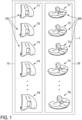
- a posterior stabilized knee prosthesis system 1 comprises a set 10 of femoral components 100 of different sizes F1 to F9 and a set 20 of tibial components 200 of different sizes T1 to T9.
- the differently sized femoral components 100 are configured for attachment to distal femurs of different sizes.
- the differently sized tibial components 200 are configured for attachment to proximal tibiae of different sizes.
- the differently sized femoral and tibial components 100, 200 are configured for same-size and off-size combination to form a knee prosthesis for the replacement of the patient's natural knee joint.
- each size F1 to F9 of femoral component 100 is engageable to at least one size T1 to T9 of tibial component 200 and vice versa.
- the femoral components 100 of the set 10 have an identical design. The same applies mutatis mutandis to the tibial components 200 of the set 20.
- femoral components 100 and the tibial components 200 will be described with reference to figs. 2 to 6 and regarding a single femoral component 100 and a single tibial component 200 of the set 10 and the set 20, respectively, well knowing that the remaining components of said sets 10, 20 have identical features apart from their different sizes.
- the femoral component 100 has a pair of spaced apart condyles 111, 112.
- the condyles 111, 112 are spaced apart in medial-lateral direction and define an intercondylar notch 103.
- a posterior cam 104 is positioned in the intercondylar notch 103.
- the condyles 111, 112 can be referred to as medial condyle 111 and lateral condyle 112 or vice versa, depending on whether the femoral component 100 is used on the patient's left or right distal femur.
- Both condyles 111, 112 comprise a condyle surface 101, 102, referred to as medial condyle surface 101 and lateral condyle surface 102. Both condyle surfaces 101, 102 are curved in the sagittal plane E (see fig. 5 ). In the embodiment shown, the condyle surfaces 101, 102 are at least substantially symmetrical with respect to a sagittal symmetry plane, while other embodiments comprise non-symmetrical condyle surfaces. Further features of the condyle surfaces 101, 102 will be described with reference to the lateral condyle surface 102 and fig. 5 . Due to the symmetrical design of the condyle surfaces 101, 102 the further features described with respect to the lateral condyle surface 102 apply mutatis mutandis to the medial condyle surface 101.
- the (lateral) condyle surface 102 is curved in the sagittal plane E with multiple at least substantially tangential radii R0, R1 to R5 of curvature.
- the radius R0 is located anterior to a femoral dwell point FDP of the condyle surface 102.
- the radii R1 to R5 are located posterior to the dwell point FDP.
- the femoral dwell point FDP denotes the most distal point of the condyle surface 102 and/or the condyle 112.
- the radius R0 can therefore also be denoted as anterior radius R0.
- the radii R1 to R5 can also be denoted as posterior radii of the femoral component 100.
- the tibial component 200 comprises bearing surfaces 201, 202 that can also be denoted as medial bearing surface 201 and lateral bearing surface 202 or vice versa, depending on whether the tibial component 200 is used on the patient's left or right proximal tibia.
- the bearing surfaces 201, 202 are spaced apart in medial-lateral direction.
- the tibial component 200 further comprises a post 203 extending upwardly, i.e., in proximal direction, from the bearing surfaces 201, 202.
- the femoral component 100 and the tibial component 200 are configured to articulate by contact between the condyle surfaces 101, 102 and the bearing surfaces 201, 202 (see fig. 4 ).
- the components 100, 200 are also configured to articulate by contact between the cam 104 and the post 203, the cam 104 and the post 203 not being engaged throughout the full range of motion of the knee prosthesis.
- the bearing surfaces 201, 202 are symmetrical with respect to a sagittal symmetry plane, while other embodiments have non-symmetrical bearing surfaces. Further features of the bearing surfaces 201, 202 will be described with reference to fig. 6 . Features described regarding the medial bearing surface 201 apply mutatis mutandis to the lateral bearing surface 201 and vice versa.
- the (medial) bearing surface 201 is curved in the sagittal plane E (see fig. 5 ) with multiple at least substantially tangential radii AR, PR of curvature.
- the bearing surface 201 comprises a tibial dwell point TDP denoting the most distal point on the bearing surface 201.
- the radius AR is positioned anterior to the tibial dwell point TDP and can therefore be denoted as anterior radius (of the tibial component 200).
- the radius PR is positioned posterior to the tibial dwell point TDP and can therefore be denoted as posterior radius PR (of the tibial component 200).
- the contact between the femoral component 100 and the tibial component 200 is established between the femoral dwell point FDP and the tibial dwell point TDP, more precisely: between the respective dwell points on the medial and lateral surfaces, respectively.
- the "point" of contact moves along the posterior radii R1 to R5 of the femoral component 100 and the posterior radius PR of the tibial component 200.
- the cam 104 initially engages the post 203 at a degree of flexion between 35° and 60°, more precisely between 45° and 60°.
- the range of 45° to 60° corresponds to the degree of flexion when a native posterior cruciate ligament starts to action in a native knee.
- the radii R0, R1 to R5 of the condyle surfaces 101, 102 each increase monotonically across increasing size F1 to F9 of the femoral components 100.
- the radii AR, PR of curvature of the bearing surfaces 201, 202 each increase monotonically across increasing size T1 to T9 of the tibial components (see table 502 shown in fig. 10 ).
- F1 is the smallest and F9 is the largest size of the femoral components 100.
- T1 is the smallest and T9 is the largest size of the tibial components 200.
- the total number of sizes, in this case nine femoral and nine tibial sizes, is purely exemplary. In other embodiments, the set 10 has less or more than nine femoral sizes, for example two, three, four, five, six, seven, eight, ten, eleven, twelve or even more sizes. The same applies mutatis mutandis with respect to the number of tibial sizes.
- the radii R1 to R5 can be denoted as first radius R1, second radius R2, third radius R3, fourth radius R4 and fifth radius R5 of curvature of the condyle surface 101, 102.
- the condyle surfaces 101, 102 comprise less or more than five (posterior) radii, for example two, three, four, six, seven, eight or even more radii.
- the respective radius increases or stays the same with increasing size F1 to F9 of the femoral component 100 and increasing size T1 to T9 of the tibial component 200, respectively.
- the radii R0, R1 to R5 of the femoral components 100 increase strictly monotonically (see table 500).
- a strictly monotonic or monotone increase means that each of the radii R0, R1 to R5 increases starting from the smallest size F1 to every further size F2 to F8 until the largest size F9.
- the posterior radius PR increases from the smallest size T1 to every further size T2 to T8 until the largest size T9 of the tibial components 200.
- the anterior radius AR does not increase strictly monotonically over the full range of sizes T1 to T9. With reference to table 502, it is evident that the anterior radius AR has equal values for the sizes T7, T8, T9. In other embodiments, also the anterior radius AR increases strictly monotonically.
- the radii R1 to R5 of the condyle surfaces 101, 102 each increase linearly across increasing size F1 to F9 of the femoral components 100. Said linear increase is shown in graph 600 of fig. 9 .
- the graph 601 shows that the posterior radius PR of the bearing surfaces 201, 202 increases linearly across increasing size T1 to T9 of the tibial components 200.
- the anterior radius AR does not increase linearly across the full range of sizes T1 to T9. Instead, the increase is linear in-between the sizes T1 and T7, while there is no increase from size T7 to size T8 and from size T8 to size T9.
- the afore-mentioned strictly monotonic increases are not linear, but instead progressive, in particular exponential, and/or degressive with increasing component size.
- the femoral component 100 has a total anterior-posterior dimension APF extending between an anterior edge AEF and a posterior edge (without reference sign).
- the total anterior-posterior dimension APF increases linearly over increasing femoral component size F1 to F9 (see column 2 of table 500 in fig. 7 ). Due to the proportional dependence between femoral component size F1 to F9 and total anterior-posterior dimension APF, the linear increase of the radii R1 to R5 shown in graph 600 of fig. 7 is also linear over increasing total anterior-posterior dimension APF.
- the tibial component 200 has a total anterior-posterior dimension APT extending between an anterior edge AET and a posterior edge (without reference sign).
- the total anterior-posterior dimension APT of the tibial component 200 increases linearly over increasing tibial component size T1 to T9.
- the linear increase of the posterior radius PR illustrated in graph 601 of fig. 11 is linear over increasing total anterior-posterior dimension APT of the tibial components 200 as well.
- the femoral dwell point FDP is positioned at an anterior-posterior distance DDF from the anterior edge AEF.
- the anterior-posterior distance DDF between the femoral dwell point FDP and the anterior edge AEF increases monotonically across increasing femoral component size F1 to F9. More precisely, in the embodiment shown, said increase is linear.
- a ratio between the total anterior-posterior dimension APF and the anterior-posterior distance DDF is constant for all femoral component sizes F1 to F9 (see graph 602 of fig. 12 ).
- said ratio i.e., a relative anterior-posterior position of the femoral dwell point DDF, is 0.60.
- the anterior-posterior distance DDF is 60% of the total anterior-posterior dimension APF for all femoral component sizes F1 to F9. In other embodiments, said ratio is between 0.55 and 0.65.
- the tibial dwell point TDP is positioned in an anterior-posterior distance DDT from the anterior edge AET of the tibial component 200.
- Said distance DDT increases monotonically across increasing tibial component size T1 to T9. More precisely, in the embodiment shown, said increase is linear.
- the total anterior-posterior dimension APT is proportional to the tibial component size
- a ratio between the anterior-posterior distance DDT and the total anterior-posterior dimension APT stays constant for all tibial component sizes T1 to T9.
- Said ratio i.e., a relative anterior-posterior position of the tibial dwell point TDP, is shown in graph 603 of fig. 13 .
- said ratio is 0.65.
- the anterior-posterior distance DDT is 65% of the total anterior-posterior dimension APT for all tibial component sizes T1 to T9.
- the relative value is between 60% and 70%.
- the radii R0, R1 to R5 of the condyle surfaces 101, 102 - for each size F1 to F9 - decrease in posterior direction along the condyle surface 101, 102.
- the anterior radius R0 is larger than the first radius R1
- the first radius R1 is larger than the second radius R2
- the second radius R2 is larger than the third radius R3
- the third radius R3 is larger than the fourth radius R4
- the fourth radius R4 is larger than the fifth radius R5.
- the contact "point" between the femoral component 100 and the tibial component 200 moves along different curved surface sections C1 to C5 of the (lateral) condyle surface 102 (see fig. 5 ) and analogously the (medial) condyle surface 101.
- a first curved surface section C1 has the first radius R1
- a second curved surface section C2 has the second radius R2
- a third curved surface section C3 has the third radius R3
- a fourth curved surface section C4 has the fourth radius R4
- a fifth curved surface section C5 has the fifth radius R5.
- the first curved surface section C1 contacts the respective bearing surface 201, 202 during flexion between (full) extension and a first degree of flexion ⁇ 1 (see column 3 of table 501 in fig. 8 ).
- the second curved surface section C2 is in contact between the first degree of flexion ⁇ 1 and a larger second degree of flexion ⁇ 2 (see column 4 of table 501).
- the third curved surface section C3 is in contact between the second degree of flexion ⁇ 2 and a larger third degree of flexion ⁇ 3 (see column 5 of table 501).
- the fourth curved surface section C4 is in contact between the third degree of flexion ⁇ 3 and a larger fourth degree of flexion ⁇ 4 (see column 6 of table 501).
- the fifth curved surface section C5 is in contact between the fourth degree of flexion ⁇ 4 and a larger fifth degree of flexion ⁇ 5 (see last column of table 501).
- Table 503 of fig. 15 contains values for different ratios between the radii R1 to R5 for the set of femoral component sizes F1 to F9.
- a first ratio R1/R2 denotes the ratio between the first radius R1 and the second radius R2.
- a second ratio R2/R3 denotes the ratio between the second radius R2 and the third radius R3.
- a third ratio R3/R4 denotes the ratio between the third radius R3 and the fourth radius R4.
- a fourth ratio R4/R5 denotes the ratio between the fourth radius R4 and the fifth radius R5.
- a fifth ratio R1/R5 denotes the ratio between the first radius R1 and the fifth radius R5.
- the values in table 503 show that each ratio decreases - at least slightly - over increasing femoral component size F1 to F9. In the embodiment shown, said decrease is strictly monotonic for each of the ratios R1/R2, R2/R3, R3/R4, R4/R5 and R1/R5.
- Table 503 further shows that the difference between the first (posterior) radius R1 and the last radius, in the present embodiment the fifth radius R5, is relatively small. The difference is smaller than in some prior art designs and leads to a less oval, rounder shape of the condyle surface in the sagittal plane (see fig. 5 ). Further, table 503 shows that the difference between one radius to the next radius - and therefore the ratios R1/R2, R2/R3, R3/R4, R4/R5 - is relatively small. Hence, said ratios range at approximately 1.
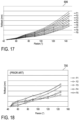
- Fig. 17 shows a graph 606 illustrating the rollback movement during flexion for different femoral component sizes F1 to F9.
- the evolution of the rollback is monotonic over increasing degrees of flexion and regarding the femoral component sizes F1 to F9.
- rollback is largest for the largest size F9 and smallest for the smallest size F1.
- the rollback increases monotonically over increasing degree of flexion.
- graph 700 of fig. 18 illustrates the rollback behavior of a prior art design.
- Graph 700 shows that a monotonic increase of rollback over increasing femoral component size is not guaranteed for all degrees of flexion.
- the kinematic behavior of the prior art design illustrated in graph 700 is less predictable than the kinematic behavior illustrated by means of graph 606.
Landscapes
- Health & Medical Sciences (AREA)
- Orthopedic Medicine & Surgery (AREA)
- Physical Education & Sports Medicine (AREA)
- Cardiology (AREA)
- Oral & Maxillofacial Surgery (AREA)
- Transplantation (AREA)
- Engineering & Computer Science (AREA)
- Biomedical Technology (AREA)
- Heart & Thoracic Surgery (AREA)
- Vascular Medicine (AREA)
- Life Sciences & Earth Sciences (AREA)
- Animal Behavior & Ethology (AREA)
- General Health & Medical Sciences (AREA)
- Public Health (AREA)
- Veterinary Medicine (AREA)
- Prostheses (AREA)
Abstract
Description
- The invention relates to a posterior stabilized knee prosthesis system, comprising: a set of femoral components of different sizes configured for attachment to distal femurs of different sizes, each femoral component having a pair of spaced apart condyles defining an intercondylar notch therebetween, and having a posterior cam positioned in the intercondylar notch, wherein at least one of the condyles has a condyle surface curved in the sagittal plane with multiple at least substantially tangential radii of curvature; and a set of tibial components of different sizes configured for attachment to proximal tibiae of different sizes, each tibial component having a bearing surface curved in the sagittal plane with multiple at least substantially tangential radii of curvature, and having a post extending upwardly from the bearing surface; wherein each size of femoral component is engageable to at least one size of tibial component to articulate by contact between the condyle surface and the bearing surface and/or by contact between the cam and the post.
- Total knee arthroplasty (TKA) is a well-known surgical procedure by which a patient's deceased and/or damaged natural knee joint is replaced by a knee prosthesis. Typical knee prostheses are designed to replicate the movement of the patient's natural joint over the full range of motion (ROM), throughout and between full flexion and extension and in all planes (coronalvarus/valgus, sagittal-flexion, transverse-rotation).
- Typical knee prostheses comprise a femoral component and a tibial component configured to be secured to a surgically-prepared distal end of a patient's femur and a surgically-prepared proximal end of the patient's tibia, respectively. The femoral component typically comprises a condyle surface with multiple tangential radii of curvature. The tibial component typically comprises a bearing surface with multiple tangential radii of curvature. As the knee is flexed and extended, the condyle surface and the bearing surface articulate and undergo combinations of relative anterior-posterior motion and relative internal-external rotation.
- The type of knee prosthesis used may also depend on whether a patient's posterior cruciate ligament (PCL) is retained or sacrificed, i.e., removed, during surgery. A removal of the PCL may be necessary in case of insufficiency due to disease and/or damage. If the PCL is removed, posterior stabilized knee prostheses are oftentimes used and intend to provide additional support and/or control of the knee movement by replicating the function of the natural PCL. Typical posterior stabilized knee prostheses comprise a posterior cam on the femoral component and a post on the tibial component. The cam and the post typically intend to engage at a degree of flexion that resembles the degree of flexion when the native PCL would start its action.
- To accommodate for different patients' anatomies, in particular for different femoral and tibial bone sizes, differently sized femoral and tibial components are provided. Said differently sized components form a knee prosthesis system. During surgery the surgeon decides which component sizes fit best. Due to the patient's anatomy or other surgical reasons it may be necessary to combine different sizes of femoral and tibial components of the knee prosthesis system.
-
EP 2 726 020 B1 discloses a posterior stabilized knee prosthesis system having the features specified in the preamble ofclaim 1, wherein the radii of curvature of the condyle surfaces decrease gradually between early-flexion and mid-flexion and increase during mid-flexion. Moreover,EP 2 726 020 B1 teaches that at least one radius of the radii of the condyle surfaces decreases over increasing femoral component size, while other radii increase. - It is an object of the invention to provide a posterior stabilized knee prosthesis system of the type mentioned at the beginning, which allows for an improved prosthetic kinematic behavior.
- This object is solved by providing a posterior stabilized knee prosthesis system with the features of
claim 1. Preferred embodiments are defined in the dependent claims. - According to the invention, the radii of curvature of the condyle surface each increase monotonically across increasing size of the femoral components, and the radii of curvature of the bearing surface each increase monotonically across increasing size of the tibial components.
- The invention reduces size dependent effects on the prosthesis' kinematic behavior. The inventors have found that the monotonic increase of the radii of curvature of the condyle surface and the radii of curvature of the bearing surface of the differently sized femoral and tibial components leads to a more predictable, homogeneous kinematic behavior regarding different same-sized combinations of femoral and tibial components as well as off-sized component combinations. In particular, the invention allows for a similar, and therefore predictable roll-back behavior for same-sized and off-sized component combinations.
- The set of femoral components comprises at least three, preferably at least five, more preferably at least nine, different sizes. The same applies mutatis mutandis for the set of tibial components. The term "size" refers to a value within a sizing system and/or metric. A same-sized combination of components refers to a combination of a femoral component and a tibial component being assigned to the same value within said sizing system and/or metric. "Same-sized" does not mean that a given combination of femoral and tibial components has the same component dimensions. An "off-sized" combination of components refers to a given combination of a femoral component and a tibial component having different component sizes.
- The condyle surfaces of the differently sized femoral components are each having said multiple radii, for example at least a first radius, a second radius and a third radius. According to the invention each radius increases monotonically over increasing femoral component size, for example a (small) first size, a (medium) second size and a (large) third size. "Monotonic" or "monotone" means that said radii are not decreasing over increasing femoral component size. Hence, because of the monotonic increase, the first radius of the third size femoral component is larger than or equal to the first radius of the second size femoral component. In turn, the first radius of the second size femoral component is larger than or equal to the first radius of the first size femoral component. Moreover, the second radius of the third size femoral component is larger than or equal to the second radius of the second size femoral component. In turn, the second radius of the second size femoral component is larger than or equal to the second radius of the first size femoral component. The same applies mutatis mutandis regarding the third radii. Put in other words: From one size to a larger femoral component size none of the radii decreases. The multiple radii are each uniform and/or discrete, i.e., each radius - for a given size of femoral component - has a fixed non-gradual value. In embodiments, the multiple radii of the condyle surface are tangential. Preferably, the multiple radii of the condyle surface are positioned posterior to a dwell point of the condyle surface and/or posterior to an anterior radius. The multiple radii of the condyle surface can therefore be referred to as posterior radii.
- The bearing surface of the differently sized tibial components are each having said multiple radii of curvature, for example a first radius and a second radius. According to the invention, each radius of the bearing surface increases monotonically over increasing tibial component size, for example for a (small) first size, a (medium) second size and a (large) third size. As a result of the monotonic increase, the first radius of the third size tibial component is larger than or equal to the first radius of the second size tibial component. In turn, the first radius of the second size tibial component is larger than or equal to the first radius of the first size tibial component. Moreover, the second radius of the third size tibial component is larger than or equal to the second radius of the second size tibial component. Moreover, the second radius of the second size tibial component is larger than or equal to the second radius of the first size tibial component. Put in other words, none of the radii of the bearing surfaces decreases with increasing size of the tibial components. The multiple radii of the bearing surfaces are each uniform and/or discrete, i.e., each radius - for a given size of tibial component - has a fixed non-gradual value. In embodiments, the multiple radii of the bearing surfaces are tangential. Preferably, the bearing surfaces each have a first radius and a second radius, wherein the first radius is an anterior radius positioned anterior to a dwell point of the respective bearing surface and the second radius is a posterior radius positioned posterior to said dwell point.
- In one embodiment, the increase of the radii of curvature of the condyle surface across increasing size of the femoral components is strictly monotonic and/or the increase of the radii of curvature of the bearing surface across increasing size of the tibial components is strictly monotonic. Hence, the respective radii are strictly increasing with increasing size of the femoral components or the tibial components, respectively. In this embodiment therefore a radius on a larger size femoral component is always larger than the respective radius on a smaller size femoral component. The same applies mutatis mutandis with respect to larger and smaller size tibial components and their respective radii. In embodiments, the strictly monotonic increase regarding the radii of the condyle surfaces is at least substantially proportional, i.e., linear, progressive, in particular exponential, and/or degressive with increasing femoral component size. The same applies mutatis mutandis with respect to the strictly monotonic increase of the radii of the bearing surfaces.
- In one embodiment, the radii of curvature of the condyle surface each increase at least substantially linearly across increasing size of the femoral components and/or the radii of curvature of the bearing surface each increase at least substantially linearly across increasing size of the tibial components. The inventors have found that said at least substantially linear increase leads to particularly advantageous kinematic behavior for same-sized as well as off-sized component combinations.
- In one embodiment, the condyle surface of each femoral component has a femoral dwell point, wherein an anterior-posterior distance between the femoral dwell point and an anterior edge of the condyle surface increases, preferably strictly, monotonically across increasing size of the femoral components. The femoral dwell point is the most distal point of the respective condyle surface. The inventors have found that the, in particular strictly, monotonic increase of the anterior-posterior distance between the femoral dwell point and the anterior edge of the respective condyle surface (for each femoral component size) allows for further improvements in the prosthetic kinematic behavior. In particular, the kinematic behavior is less size dependent in comparison to designs featuring a fixed anterior-posterior distance for all sizes. In embodiments, the strictly monotonic increase is at least substantially proportional, i.e., linear, progressive, in particular exponential, and/or degressive with increasing tibial component size.
- In one embodiment, the anterior-posterior distance between the femoral dwell point and the anterior edge of the condyle surface increases at least substantially linearly across increasing size of the femoral components. Given that a total anterior-posterior dimension of the femoral components increases at least substantially linearly across increasing component size, the at least substantially linearly increase of the anterior-posterior distance corresponds to a fixed percentage of said total anterior-posterior dimension. In embodiments, the increase of the anterior-posterior distance is linear across increasing size of the femoral components.
- In one embodiment, the anterior-posterior distance is between 55% and 65%, preferably 60%, of a total anterior-posterior dimension of the respective femoral component. The inventors have found that 60% is an at least nearly optimal value regarding the resulting kinematic behavior.
- In one embodiment, the bearing surface of each tibial component has a tibial dwell point, wherein an anterior-posterior distance between the tibial dwell point and an anterior edge of the bearing surface increases, preferably strictly, monotonically across increasing size of the tibial components. The tibial dwell point is the most distal point of the bearing surface of the respective tibial component. The, preferably strictly, monotonic increase of the anterior-posterior distance between the tibial dwell point and the anterior edge of the respective bearing surface leads to further improvements in the kinematic behavior. In embodiments, the strictly monotonic increase is at least substantially proportional, i.e., linear, progressive, in particular exponential, and/or degressive with increasing tibial component size.
- In one embodiment, the anterior-posterior distance between the tibial dwell point and an anterior edge of the bearing surface increases at least substantially linearly across increasing size of the tibial components. Given that a total anterior-posterior dimension of the tibial components increases at least substantially linearly across increasing size of the tibial components. This corresponds to an at least substantially fixed percentage of the anterior-posterior distance with respect to the total anterior-posterior dimension of the respective tibial component.
- In one embodiment, the anterior-posterior distance is between 60% and 70%, preferably 65%, of a total anterior-posterior dimension of the respective tibial component. The inventors have found that 65% is an at least nearly optimal value regarding the resulting kinematic behavior. In embodiments, an anterior-posterior position of the post in relation to the tibial dwell point has a fixed value over increasing size of the tibial components. Hence, the position of the post evolves smoothly over increasing size of the tibial components. In particular, a percentage of the position of the post decreases linearly over increasing size of the tibial components. The inventors have found that this may lead to a further improvement of the kinematic behavior. In particular, size dependencies for both same-sized and off-sized component combinations can be further reduced.
- In one embodiment, the multiple at least substantially tangential radii of curvature of the condyle surface of each femoral component decrease, preferably strictly, monotonically in posterior direction along the condyle surface. In contrast to prior art designs featuring at least one increasing radius in posterior direction along the condyle surface, this embodiment may lead to a further improved kinematic behavior, in particular during a movement between extension and full flexion.
- In one embodiment, the condyle surface of each femoral component has a first curved surface section with a first radius of curvature contacting the bearing surface during flexion between extension and a first degree of flexion, and a second curved surface section with a second radius of curvature contacting the bearing surface during flexion between the first degree of flexion and a larger second degree of flexion. Preferably, in extension the femoral dwell point and the tibial dwell point of the respective components of a given component combination contact each other. The first curved surface section is positioned posterior from the femoral dwell point. The second curved surface section is positioned posterior from the first curved surface section. Preferably the first radius and/or the second radius is unitary and/or discrete, i.e., does not change its value along the respective surface section.
- In one embodiment, a ratio of the first radius of curvature to the second radius of curvature decreases, preferably strictly, monotonically across increasing size of the femoral components. In comparison to prior art designs featuring a substantially constant or slightly increasing ratio, this embodiment may lead to further improvements regarding the kinematic behavior.
- In one embodiment, the ratio of the first radius of curvature to the second radius of curvature decreases in the range of 1.380 to 1.240. Hence, the ratio is 1.380 for the smallest size femoral component and 1.240 for the largest size femoral component of the set of femoral components.
- In one embodiment, the condyle surface of each femoral component has a third curved surface section with a third radius of curvature contacting the bearing surface during flexion between the second degree of flexion and a larger third degree of flexion, wherein a ratio of the second radius of curvature to the third radius of curvature decreases, preferably strictly, monotonically across increasing size of the femoral components. The third curved surface section is positioned posterior in relation to the second curved surface section. In comparison to prior art designs featuring an increasing or nearly linear ratio of the second to the third radius of curvature, this embodiment may lead to a further improved kinematic behavior.
- In one embodiment, the ratio of the second radius of curvature to the third radius of curvature decreases in the range of 1.031 to 1.019. Hence, the ratio of the second to the third radius of curvature decreases moderately over increasing femoral component size. Moreover, there is only a slight decrease from the second to the third radius on a given femoral component. Put in other words, the "gap" between the second radius and the third radius is less abrupt than in some prior art designs, which allows for a more linear/smooth kinematic behavior during flexion between the second and the third degree of flexion. In embodiments, the ratio for the smallest femoral component is 1.031 and 1.019 for the largest femoral component of the set of femoral components.
- In one embodiment, the condyle surface of each femoral component has a fourth curved surface section with a fourth radius of curvature contacting the bearing surface during flexion between the third degree of flexion and a larger fourth degree of flexion, wherein a ratio of the third radius of curvature to the fourth radius of curvature decreases, preferably strictly, monotonically across increasing size of the femoral components. The fourth curved surface section is posterior in relation to the third curved surface section. In comparison to prior art designs featuring a nearly constant or increasing ratio of the third radius to the fourth radius, this embodiment may result in further improvements of the kinematic behavior.
- In one embodiment, the ratio of the third radius of curvature to the fourth radius of curvature decreases in the range of 1.059 to 1.036. The ratio is 1.059 for the smallest size and 1.036 for the largest size femoral component of the set of femoral components. Hence, for both components, the smallest and the largest as well as for those components in-between, the "gap" between the third and the fourth radius is relatively small and/or less abrupt than in some prior art designs.
- In one embodiment, the condyle surface of each femoral component has a fifth curved surface section with a fifth radius of curvature contacting the bearing surface during flexion between the fourth degree of flexion and a larger fifth degree of flexion, wherein a ratio of the fourth radius of curvature to the fifth radius of curvature decreases, preferably strictly, monotonically across the size of the femoral components. In comparison to prior art designs featuring a nearly constant or increasing ratio of the fourth to the fifth radius of curvature, this embodiment may lead to further improvements regarding the kinematic behavior. The fifth curved surface section is posterior in relation to the fourth curved surface section.
- In one embodiment, the ratio of the fourth radius of curvature to the fifth radius of curvature decreases in the range of 1.020 to 1.012. As a result, there is only a very small "gap" between the fourth and fifth radius for all femoral component sizes. Put in other words, the transition from the fourth to the fifth radius is smaller than in some prior art designs. This may lead to a more linear/smooth kinematic behavior during an articulation of the fourth and fifth curved surface section with the bearing surface. In embodiments, the ratio is 1.020 for the smallest size and 1.012 for the largest size femoral component of the set of femoral components.
- In one embodiment, a ratio of the first radius of curvature to the fifth radius of curvature decreases, preferably strictly, monotonically in the range of 1.537 to 1.326. Preferably, the fifth radius of curvature is the most posterior and/or the last radius on the respective condyle surface. Hence, the difference or "gap" between the first radius and the fifth, in particular last, radius is less than in some prior art designs. As a result, the condyle surfaces each have a rounder, less oval shape. This may lead to further improved kinematic properties. In embodiments, the ratio of the first to the fifth radius is 1.537 for the smallest and 1.326 for the largest component of the set of femoral components.
- In one embodiment, the cam initially engages the post at a degree of flexion between 35° and 60°, preferably between 45° and 60°. As a result, initial cam-post engagement takes place at a degree of flexion that corresponds to a degree of flexion when a native PCL starts to act in a native knee. In embodiments, the engagement degree of flexion is smaller than the first degree of flexion. In other embodiments, the engagement degree of flexion is larger than the first degree of flexion and smaller than the second degree of flexion. In yet other embodiments, the engagement degree of flexion is larger than the second degree of flexion and smaller than the third degree of flexion. In still other embodiments, the engagement degree of flexion is larger than the third degree of flexion and smaller than the fourth degree of flexion. Preferably, the engagement degree of flexion is larger than the second degree of flexion and smaller than the third degree of flexion.
- In the following, a preferred embodiment of the invention is described in detail with reference to the drawings. Throughout the drawings, same elements are denoted with same reference numerals/signs. The drawings schematically show:
- fig. 1
- a perspective view of an embodiment of a posterior stabilized knee prosthesis system according to the invention, the knee prosthesis system having a set of differently sized femoral components and a set of differently sized tibial components;
- fig. 2
- a perspective view of a femoral component of the knee prosthesis system according to
fig. 1 ; - fig. 3
- a perspective view of a tibial component of the knee prosthesis system according to
fig. 1 ; - fig. 4
- a perspective view of a knee prosthesis comprising the femoral and tibial components according to
figs. 2 and 3 ; - fig. 5
- a side view of the femoral component according to
fig. 2 ; - fig. 6
- another perspective view of the tibial component according to
fig. 3 ; - fig. 7
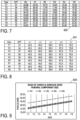
- a table containing a set of total anterior-posterior dimension values and a set of radii of curvature values for the set of differently sized femoral components;
- fig. 8
- a table containing the set of total anterior-posterior dimensions and a set of degree of flexion values for the set of differently sized femoral components;
- fig. 9
- a graph showing the increase of the radii contained in the table of
fig. 7 over the size of the femoral components; - fig. 10
- a table containing a set of total anterior-posterior dimension values and a set of radii of curvature values for the set of differently sized tibial components;
- fig. 11 a
- graph showing the radii of curvature values contained in the table of
fig. 10 over increasing tibial component size; - fig. 12
- a graph of a relative anterior-posterior position of a femoral dwell point over the total anterior-posterior dimension values of the differently sized femoral components as contained in the table of
figs. 7 ; - fig. 13
- a graph of a relative anterior-posterior position of a tibial dwell point over the total anterior-posterior dimension values of the tibial components as contained in the table of
fig. 10 ; - fig. 14
- a graph of the radii of curvature values contained in the table of
fig. 7 ; - fig. 15
- a table containing the set of total anterior-posterior dimension values and a set of ratios of the radii of curvature values contained in the table of
fig. 7 ; - fig. 16
- a graph of the ratios of radii contained in the table of
fig. 15 over increasing femoral component size; - fig. 17
- a graph of a roll-back movement over a degree of flexion for the differently sized femoral components and
- fig. 18
- a graph of a roll-back movement over the degree of flexion for differently sized femoral components according to a prior art design.
- According to
fig. 1 , a posterior stabilizedknee prosthesis system 1 comprises aset 10 offemoral components 100 of different sizes F1 to F9 and aset 20 oftibial components 200 of different sizes T1 to T9. The differently sizedfemoral components 100 are configured for attachment to distal femurs of different sizes. The differently sizedtibial components 200 are configured for attachment to proximal tibiae of different sizes. Depending on a patient's anatomy, in particular the femoral and tibial bone sizes, the differently sized femoral andtibial components femoral component 100 is engageable to at least one size T1 to T9 oftibial component 200 and vice versa. - Apart from their different sizes F1 to F9, the
femoral components 100 of theset 10 have an identical design. The same applies mutatis mutandis to thetibial components 200 of theset 20. - Further features of the
femoral components 100 and thetibial components 200 will be described with reference tofigs. 2 to 6 and regarding a singlefemoral component 100 and asingle tibial component 200 of theset 10 and theset 20, respectively, well knowing that the remaining components of said sets 10, 20 have identical features apart from their different sizes. - Referring to
fig. 2 , thefemoral component 100 has a pair of spaced apartcondyles condyles intercondylar notch 103. Aposterior cam 104 is positioned in theintercondylar notch 103. Thecondyles medial condyle 111 andlateral condyle 112 or vice versa, depending on whether thefemoral component 100 is used on the patient's left or right distal femur. Bothcondyles condyle surface medial condyle surface 101 andlateral condyle surface 102. Both condyle surfaces 101, 102 are curved in the sagittal plane E (seefig. 5 ). In the embodiment shown, the condyle surfaces 101, 102 are at least substantially symmetrical with respect to a sagittal symmetry plane, while other embodiments comprise non-symmetrical condyle surfaces. Further features of the condyle surfaces 101, 102 will be described with reference to thelateral condyle surface 102 andfig. 5 . Due to the symmetrical design of the condyle surfaces 101, 102 the further features described with respect to thelateral condyle surface 102 apply mutatis mutandis to themedial condyle surface 101. - Referring to
fig. 5 , the (lateral)condyle surface 102 is curved in the sagittal plane E with multiple at least substantially tangential radii R0, R1 to R5 of curvature. The radius R0 is located anterior to a femoral dwell point FDP of thecondyle surface 102. The radii R1 to R5 are located posterior to the dwell point FDP. The femoral dwell point FDP denotes the most distal point of thecondyle surface 102 and/or thecondyle 112. The radius R0 can therefore also be denoted as anterior radius R0. The radii R1 to R5 can also be denoted as posterior radii of thefemoral component 100. - Referring to
fig. 3 , thetibial component 200 comprises bearingsurfaces medial bearing surface 201 andlateral bearing surface 202 or vice versa, depending on whether thetibial component 200 is used on the patient's left or right proximal tibia. The bearing surfaces 201, 202 are spaced apart in medial-lateral direction. Thetibial component 200 further comprises apost 203 extending upwardly, i.e., in proximal direction, from the bearing surfaces 201, 202. - The
femoral component 100 and thetibial component 200 are configured to articulate by contact between the condyle surfaces 101, 102 and the bearing surfaces 201, 202 (seefig. 4 ). Thecomponents cam 104 and thepost 203, thecam 104 and thepost 203 not being engaged throughout the full range of motion of the knee prosthesis. - In the embodiment shown, the bearing surfaces 201, 202 are symmetrical with respect to a sagittal symmetry plane, while other embodiments have non-symmetrical bearing surfaces. Further features of the bearing surfaces 201, 202 will be described with reference to
fig. 6 . Features described regarding themedial bearing surface 201 apply mutatis mutandis to thelateral bearing surface 201 and vice versa. - The (medial) bearing
surface 201 is curved in the sagittal plane E (seefig. 5 ) with multiple at least substantially tangential radii AR, PR of curvature. The bearingsurface 201 comprises a tibial dwell point TDP denoting the most distal point on thebearing surface 201. The radius AR is positioned anterior to the tibial dwell point TDP and can therefore be denoted as anterior radius (of the tibial component 200). The radius PR is positioned posterior to the tibial dwell point TDP and can therefore be denoted as posterior radius PR (of the tibial component 200). - In full extension of the knee prosthesis depicted in
fig. 4 the contact between thefemoral component 100 and thetibial component 200 is established between the femoral dwell point FDP and the tibial dwell point TDP, more precisely: between the respective dwell points on the medial and lateral surfaces, respectively. When the knee prosthesis is flexed, the "point" of contact moves along the posterior radii R1 to R5 of thefemoral component 100 and the posterior radius PR of thetibial component 200. - In the embodiment shown, the
cam 104 initially engages thepost 203 at a degree of flexion between 35° and 60°, more precisely between 45° and 60°. The range of 45° to 60° corresponds to the degree of flexion when a native posterior cruciate ligament starts to action in a native knee. - As can be seen from table 500 shown in
fig. 7 , the radii R0, R1 to R5 of the condyle surfaces 101, 102 each increase monotonically across increasing size F1 to F9 of thefemoral components 100. Moreover, the radii AR, PR of curvature of the bearing surfaces 201, 202 each increase monotonically across increasing size T1 to T9 of the tibial components (see table 502 shown infig. 10 ). - In the embodiment shown, F1 is the smallest and F9 is the largest size of the
femoral components 100. Correspondingly, T1 is the smallest and T9 is the largest size of thetibial components 200. The total number of sizes, in this case nine femoral and nine tibial sizes, is purely exemplary. In other embodiments, theset 10 has less or more than nine femoral sizes, for example two, three, four, five, six, seven, eight, ten, eleven, twelve or even more sizes. The same applies mutatis mutandis with respect to the number of tibial sizes. - Referring to
figs. 5 and7 , the radii R1 to R5 can be denoted as first radius R1, second radius R2, third radius R3, fourth radius R4 and fifth radius R5 of curvature of thecondyle surface figs. 6 and10 , the same applies mutatis mutandis with respect to the radii AR, PR of the bearing surfaces 201, 202. - Because of the monotonic increase of the radii R0, R1 to R5 as well as AR and PR, the respective radius increases or stays the same with increasing size F1 to F9 of the
femoral component 100 and increasing size T1 to T9 of thetibial component 200, respectively. - In the embodiment shown, the radii R0, R1 to R5 of the
femoral components 100 increase strictly monotonically (see table 500). A strictly monotonic or monotone increase means that each of the radii R0, R1 to R5 increases starting from the smallest size F1 to every further size F2 to F8 until the largest size F9. In the embodiment shown, the same applies mutatis mutandis to the increase of the posterior radius PR of the bearing surfaces 201, 202 (see table 502 offig. 10 ). Hence, the posterior radius PR increases from the smallest size T1 to every further size T2 to T8 until the largest size T9 of thetibial components 200. The anterior radius AR, however, does not increase strictly monotonically over the full range of sizes T1 to T9. With reference to table 502, it is evident that the anterior radius AR has equal values for the sizes T7, T8, T9. In other embodiments, also the anterior radius AR increases strictly monotonically. - In the embodiment shown, the radii R1 to R5 of the condyle surfaces 101, 102 each increase linearly across increasing size F1 to F9 of the
femoral components 100. Said linear increase is shown ingraph 600 offig. 9 . Referring to graph 601 offig. 11 , the same applies mutatis mutandis regarding the posterior radius PR. Thegraph 601 shows that the posterior radius PR of the bearing surfaces 201, 202 increases linearly across increasing size T1 to T9 of thetibial components 200. The anterior radius AR, however, does not increase linearly across the full range of sizes T1 to T9. Instead, the increase is linear in-between the sizes T1 and T7, while there is no increase from size T7 to size T8 and from size T8 to size T9. - In other embodiments, the afore-mentioned strictly monotonic increases are not linear, but instead progressive, in particular exponential, and/or degressive with increasing component size.
- Further with reference to
fig. 5 , thefemoral component 100 has a total anterior-posterior dimension APF extending between an anterior edge AEF and a posterior edge (without reference sign). The total anterior-posterior dimension APF increases linearly over increasing femoral component size F1 to F9 (see column 2 of table 500 infig. 7 ). Due to the proportional dependence between femoral component size F1 to F9 and total anterior-posterior dimension APF, the linear increase of the radii R1 to R5 shown ingraph 600 offig. 7 is also linear over increasing total anterior-posterior dimension APF. - Referring to
fig. 6 , thetibial component 200 has a total anterior-posterior dimension APT extending between an anterior edge AET and a posterior edge (without reference sign). As can be seen from the values in column 2 of table 502 offig. 10 , the total anterior-posterior dimension APT of thetibial component 200 increases linearly over increasing tibial component size T1 to T9. As a result, the linear increase of the posterior radius PR illustrated ingraph 601 offig. 11 is linear over increasing total anterior-posterior dimension APT of thetibial components 200 as well. - Further referring to
fig. 5 , the femoral dwell point FDP is positioned at an anterior-posterior distance DDF from the anterior edge AEF. The anterior-posterior distance DDF between the femoral dwell point FDP and the anterior edge AEF increases monotonically across increasing femoral component size F1 to F9. More precisely, in the embodiment shown, said increase is linear. As a result, a ratio between the total anterior-posterior dimension APF and the anterior-posterior distance DDF is constant for all femoral component sizes F1 to F9 (seegraph 602 offig. 12 ). In the embodiment shown, said ratio, i.e., a relative anterior-posterior position of the femoral dwell point DDF, is 0.60. Put in other words, the anterior-posterior distance DDF is 60% of the total anterior-posterior dimension APF for all femoral component sizes F1 to F9. In other embodiments, said ratio is between 0.55 and 0.65. - Referring to
fig. 6 , the tibial dwell point TDP is positioned in an anterior-posterior distance DDT from the anterior edge AET of thetibial component 200. Said distance DDT increases monotonically across increasing tibial component size T1 to T9. More precisely, in the embodiment shown, said increase is linear. Since the total anterior-posterior dimension APT is proportional to the tibial component size, a ratio between the anterior-posterior distance DDT and the total anterior-posterior dimension APT stays constant for all tibial component sizes T1 to T9. Said ratio, i.e., a relative anterior-posterior position of the tibial dwell point TDP, is shown ingraph 603 offig. 13 . In the embodiment shown, said ratio is 0.65. Put in other words, the anterior-posterior distance DDT is 65% of the total anterior-posterior dimension APT for all tibial component sizes T1 to T9. In other embodiments the relative value is between 60% and 70%. - Again, with reference to
fig. 5 and table 500 offig. 7 , it is evident that the radii R0, R1 to R5 of the condyle surfaces 101, 102 - for each size F1 to F9 - decrease in posterior direction along thecondyle surface - Starting from full extension, i.e., a contact between the femoral dwell point FDP and the tibial dwell point TDP, the contact "point" between the
femoral component 100 and thetibial component 200 moves along different curved surface sections C1 to C5 of the (lateral) condyle surface 102 (seefig. 5 ) and analogously the (medial)condyle surface 101. - In the embodiment shown, a first curved surface section C1 has the first radius R1, a second curved surface section C2 has the second radius R2, a third curved surface section C3 has the third radius R3, a fourth curved surface section C4 has the fourth radius R4 and a fifth curved surface section C5 has the fifth radius R5.
- The first curved surface section C1 contacts the
respective bearing surface fig. 8 ). The second curved surface section C2 is in contact between the first degree of flexion α1 and a larger second degree of flexion α2 (see column 4 of table 501). The third curved surface section C3 is in contact between the second degree of flexion α2 and a larger third degree of flexion α3 (see column 5 of table 501). The fourth curved surface section C4 is in contact between the third degree of flexion α3 and a larger fourth degree of flexion α4 (see column 6 of table 501). The fifth curved surface section C5 is in contact between the fourth degree of flexion α4 and a larger fifth degree of flexion α5 (see last column of table 501). - Table 503 of
fig. 15 contains values for different ratios between the radii R1 to R5 for the set of femoral component sizes F1 to F9. A first ratio R1/R2 denotes the ratio between the first radius R1 and the second radius R2. A second ratio R2/R3 denotes the ratio between the second radius R2 and the third radius R3. A third ratio R3/R4 denotes the ratio between the third radius R3 and the fourth radius R4. A fourth ratio R4/R5 denotes the ratio between the fourth radius R4 and the fifth radius R5. A fifth ratio R1/R5 denotes the ratio between the first radius R1 and the fifth radius R5. The values in table 503 show that each ratio decreases - at least slightly - over increasing femoral component size F1 to F9. In the embodiment shown, said decrease is strictly monotonic for each of the ratios R1/R2, R2/R3, R3/R4, R4/R5 and R1/R5. - Table 503 further shows that the difference between the first (posterior) radius R1 and the last radius, in the present embodiment the fifth radius R5, is relatively small. The difference is smaller than in some prior art designs and leads to a less oval, rounder shape of the condyle surface in the sagittal plane (see
fig. 5 ). Further, table 503 shows that the difference between one radius to the next radius - and therefore the ratios R1/R2, R2/R3, R3/R4, R4/R5 - is relatively small. Hence, said ratios range at approximately 1. -
Fig. 17 shows agraph 606 illustrating the rollback movement during flexion for different femoral component sizes F1 to F9. As a result of the, in particular strictly, monotonic evolution of the design parameters, such as the radii R1 to R5 and their ratios, the evolution of the rollback is monotonic over increasing degrees of flexion and regarding the femoral component sizes F1 to F9. Put in other words, for a given degree of flexion, rollback is largest for the largest size F9 and smallest for the smallest size F1. For each size, the rollback increases monotonically over increasing degree of flexion. - In contrast to the rollback behavior illustrated in
graph 606,graph 700 offig. 18 illustrates the rollback behavior of a prior art design.Graph 700 shows that a monotonic increase of rollback over increasing femoral component size is not guaranteed for all degrees of flexion. Hence, the kinematic behavior of the prior art design illustrated ingraph 700 is less predictable than the kinematic behavior illustrated by means ofgraph 606.
Claims (21)
- A posterior stabilized knee prosthesis system (1), comprising:a set (10) of femoral components (100) of different sizes (F1 to F9) configured for attachment to distal femurs of different sizes, each femoral component (100) having a pair of spaced apart condyles (111, 112) defining an intercondylar notch (103) therebetween, and having a posterior cam (104) positioned in the intercondylar notch (103), wherein at least one of the condyles (111, 112) has a condyle surface (101, 102) curved in the sagittal plane (E) with multiple at least substantially tangential radii (R0, R1 to R5) of curvature;and a set (20) of tibial components (200) of different sizes (T1 to T9) configured for attachment to proximal tibiae of different sizes (T1 to T9), each tibial component (200) having a bearing surface (201, 202) curved in the sagittal plane (E) with multiple at least substantially tangential radii (AR, PR) of curvature, and having a post (203) extending upwardly from the bearing surface (201, 202);wherein each size (F1 to F9) of femoral component is engageable to at least one size (T1 to T9) of tibial component to articulate by contact between the condyle surface (101, 102) and the bearing surface (201, 202) and/or by contact between the cam (104) and the post (203);characterized in that the radii (R0, R1 to R5) of curvature of the condyle surface (101, 102) each increase monotonically across increasing size (F1 to F9) of the femoral components (100), and in that the radii (AR, PR) of curvature of the bearing surface (201, 202) each increase monotonically across increasing size (T1 to T9) of the tibial components (200).
- The posterior stabilized knee prosthesis system (1) according to claim 1, characterized in that the increase of the radii (R0, R1 to R5) of curvature of the condyle surface (101, 102) across increasing size (F1 to F9) of the femoral components (100) is strictly monotonic and/or in that the increase of the radii (AR, PR) of curvature of the bearing surface (201, 202) across increasing size (T1 to T9) of the tibial components (200) is strictly monotonic.
- The posterior stabilized knee prosthesis system (1) according to claim 1 or 2, characterized in that the radii (R0, R1 to R5) of curvature of the condyle surface (101, 102) each increase at least substantially linearly across increasing size (F1 to F9) of the femoral components (100) and/or in that the radii (AR, PR) of curvature of the bearing surface (201, 202) each increase at least substantially linearly across increasing size (T1 to T9) of the tibial components (200).
- The posterior stabilized knee prosthesis system (1) according to any of the preceding claims, characterized in that the condyle surface (101, 102) of each femoral component (100) has a femoral dwell point (FDP), wherein an anterior-posterior distance (DDF) between the femoral dwell point (FDP) and an anterior edge (AEF) of the condyle surface (101, 102) increases, preferably strictly, monotonically across increasing size (F1 to F9) of the femoral components (100).
- The posterior stabilized knee prosthesis system (1) according to claim 4, characterized in that the anterior-posterior distance (DDF) between the femoral dwell point (FDP) and the anterior edge (AEF) of the condyle surface (101, 102) increases at least substantially linearly across increasing size (F1 to F9) of the femoral components (100).
- The posterior stabilized knee prosthesis system (1) according to claim 4 or 5, characterized in that the anterior-posterior distance (DDF) is between 55% and 65%, preferably 60%, of a total anterior-posterior dimension (APF) of the respective femoral component (100).
- The posterior stabilized knee prosthesis system (1) according to any of the preceding claims, characterized in that the bearing surface (201, 202) of each tibial component (200) has a tibial dwell point (TDP), wherein an anterior-posterior distance (DDT) between the tibial dwell point (TDP) and an anterior edge (AET) of the bearing surface (201, 202) increases, preferably strictly, monotonically across increasing size (T1 to T9) of the tibial components.
- The posterior stabilized knee prosthesis system (1) according to claim 7, characterized in that the anterior-posterior distance (DDT) between the tibial dwell point (TDP) and the anterior edge (AET) of the bearing surface (201, 202) increases at least substantially linearly across increasing size (T1 to T9) of the tibial components (200).
- The posterior stabilized knee prosthesis system (1) according to claim 7 or 8, characterized in that the anterior-posterior distance (DDT) is between 60% and 70%, preferably 65%, of a total anterior-posterior dimension (APT) of the respective tibial component (200).
- The posterior stabilized knee prosthesis system (1) according to any of the preceding claims, characterized in that the multiple at least substantially tangential radii (R0, R1 to R5) of curvature of the condyle surface (101, 102) of each femoral component (100) decrease, preferably strictly, monotonically in posterior direction along the condyle surface (101, 102).
- The posterior stabilized knee prosthesis system (1) according to any of the preceding claims, characterized in that the condyle surface (101, 102) of each femoral component (100) hasa first curved surface section (C1) with a first radius (R1) of curvature contacting the bearing surface (201, 202) during flexion between extension and a first degree (α1), of flexion, anda second curved surface section (C2) with a second radius (R2) of curvature contacting the bearing surface (201, 202) during flexion between the first degree (α1) of flexion and a larger second degree (α2) of flexion.
- The posterior stabilized knee prosthesis system (1) according to claim 11, wherein a ratio (R1/R2) of the first radius (R1) of curvature to the second radius (R2) of curvature decreases, preferably strictly, monotonically across increasing size (F1 to F9) of the femoral components (100).
- The posterior stabilized knee prosthesis system (1) according to claim 12, characterized in that the ratio (R1/R2) of the first radius (R1) of curvature to the second radius (R2) of curvature decreases in the range of 1.380 to 1.240.
- The posterior stabilized knee prosthesis system (1) according to any of the claims 11 to 13, characterized in that the condyle surface (101, 102) of each femoral component (100) hasa third curved surface section (C3) with a third radius (R3) of curvature contacting the bearing surface (201, 202) during flexion between the second degree (α2) of flexion and a larger third degree (α3) of flexion,wherein a ratio (R2/R3) of the second radius (R2) of curvature to the third radius (R3) of curvature decreases, preferably strictly, monotonically across increasing size (F1 to F9) of the femoral components (100).
- The posterior stabilized knee prosthesis system (1) according to claim 14, characterized in that the ratio (R2/R3) of the second radius (R2) of curvature to the third radius (R3) of curvature decreases in the range of 1.031 to 1.019.
- The posterior stabilized knee prosthesis system (1) according to claim 14 or 15, characterized in that the condyle surface (101, 102) of each femoral component (100) hasa fourth curved surface section (C4) with a fourth radius (R4) of curvature contacting the bearing surface (201, 202) during flexion between the third degree (α3) of flexion and a larger fourth degree (α4) of flexion,wherein a ratio (R3/R4) of the third radius (R3) of curvature to the fourth radius (R4) of curvature decreases, preferably strictly, monotonically across increasing size (F1 to F9) of the femoral components (100).
- The posterior stabilized knee prosthesis system (1) according to claim 16, characterized in that the ratio (R3/R4) of the third radius (R3) of curvature to the fourth radius (R4) of curvature decreases in the range of 1.059 to 1.036.
- The posterior stabilized knee prosthesis system (1) according to claim 16 or 17, characterized in that the condyle surface (101, 102) of each femoral component (100) hasa fifth curved surface section (C5) with a fifth radius (R5) of curvature contacting the bearing surface (201, 202) during flexion between the fourth degree (α4) of flexion and a larger fifth degree (α5) of flexion,wherein a ratio (R4/R5) of the fourth radius (R4) of curvature to the fifth radius (R5) of curvature decreases, preferably strictly, monotonically across increasing size (F1 to F9) of the femoral components (100).
- The posterior stabilized knee prosthesis system (1) according to claim 18, characterized in that the ratio (R4/R5) of the fourth radius (R4) of curvature to the fifth radius (R5) of curvature decreases in the range of 1.020 to 1.012.
- The posterior stabilized knee prosthesis system (1) according to claim 18 or 19, characterized in that a ratio (R1/R5) of the first radius (R1) of curvature to the fifth radius (R5) of curvature decreases, preferably strictly, monotonically in the range of 1.537 to 1.326.
- The posterior stabilized knee prosthesis system (1) according to any of claims 11 to 20, wherein the cam (104) initially engages the post (203) at a degree of flexion between 35° and 60°, preferably between 45° and 60°.
Priority Applications (3)
| Application Number | Priority Date | Filing Date | Title |
|---|---|---|---|
| EP22196026.3A EP4338709B1 (en) | 2022-09-16 | 2022-09-16 | Posterior stabilized knee prosthesis system |
| JP2023143170A JP2024043498A (en) | 2022-09-16 | 2023-09-04 | Posterior stabilization prosthetic knee system |
| US18/460,853 US20240091018A1 (en) | 2022-09-16 | 2023-09-05 | Posterior stabilized knee prosthesis system |
Applications Claiming Priority (1)
| Application Number | Priority Date | Filing Date | Title |
|---|---|---|---|
| EP22196026.3A EP4338709B1 (en) | 2022-09-16 | 2022-09-16 | Posterior stabilized knee prosthesis system |
Publications (2)
| Publication Number | Publication Date |
|---|---|
| EP4338709A1 true EP4338709A1 (en) | 2024-03-20 |
| EP4338709B1 EP4338709B1 (en) | 2026-01-07 |
Family
ID=83360994
Family Applications (1)
| Application Number | Title | Priority Date | Filing Date |
|---|---|---|---|
| EP22196026.3A Active EP4338709B1 (en) | 2022-09-16 | 2022-09-16 | Posterior stabilized knee prosthesis system |
Country Status (3)
| Country | Link |
|---|---|
| US (1) | US20240091018A1 (en) |
| EP (1) | EP4338709B1 (en) |
| JP (1) | JP2024043498A (en) |
Citations (5)
| Publication number | Priority date | Publication date | Assignee | Title |
|---|---|---|---|---|
| US6699291B1 (en) * | 1999-04-01 | 2004-03-02 | Merck Biomaterial France | Antero-postero-stabilized knee prosthesis |
| US20100161067A1 (en) * | 2008-12-23 | 2010-06-24 | Aesculap Ag | Knee prosthesis |
| US20140142713A1 (en) * | 2012-11-21 | 2014-05-22 | Abraham P. Wright | Knee prosthesis assembly having proportional trochlear groove geometry |
| EP2726020B1 (en) | 2011-06-30 | 2015-11-04 | Depuy (Ireland) | Posterior stabilized orthopaedic knee prosthesis having controlled condylar curvature |
| US20220008208A1 (en) * | 2020-07-10 | 2022-01-13 | Mark A. Heldreth | Medial stabilized orthopaedic knee prosthesis |
Family Cites Families (4)
| Publication number | Priority date | Publication date | Assignee | Title |
|---|---|---|---|---|
| BR112013001669B1 (en) * | 2010-07-24 | 2021-02-09 | Zimmer, Inc | ASYMMETRIC TIBIAL COMPONENTS FOR KNEE PROSTHESIS |
| JP5571863B1 (en) * | 2011-06-16 | 2014-08-13 | ジンマー,インコーポレイティド | Femoral component for knee joint prostheses with improved joint properties |
| FR3074033A1 (en) * | 2017-11-29 | 2019-05-31 | Amplitude | RANGE OF FEMALE IMPLANTS AND TOTAL KNEE PROSTHESIS COMPRISING A FEMORAL IMPLANT SELECTED IN SUCH A RANGE OF FEMALE IMPLANTS |
| US10835380B2 (en) * | 2018-04-30 | 2020-11-17 | Zimmer, Inc. | Posterior stabilized prosthesis system |
-
2022
- 2022-09-16 EP EP22196026.3A patent/EP4338709B1/en active Active
-
2023
- 2023-09-04 JP JP2023143170A patent/JP2024043498A/en active Pending
- 2023-09-05 US US18/460,853 patent/US20240091018A1/en active Pending
Patent Citations (5)
| Publication number | Priority date | Publication date | Assignee | Title |
|---|---|---|---|---|
| US6699291B1 (en) * | 1999-04-01 | 2004-03-02 | Merck Biomaterial France | Antero-postero-stabilized knee prosthesis |
| US20100161067A1 (en) * | 2008-12-23 | 2010-06-24 | Aesculap Ag | Knee prosthesis |
| EP2726020B1 (en) | 2011-06-30 | 2015-11-04 | Depuy (Ireland) | Posterior stabilized orthopaedic knee prosthesis having controlled condylar curvature |
| US20140142713A1 (en) * | 2012-11-21 | 2014-05-22 | Abraham P. Wright | Knee prosthesis assembly having proportional trochlear groove geometry |
| US20220008208A1 (en) * | 2020-07-10 | 2022-01-13 | Mark A. Heldreth | Medial stabilized orthopaedic knee prosthesis |
Also Published As
| Publication number | Publication date |
|---|---|
| US20240091018A1 (en) | 2024-03-21 |
| EP4338709B1 (en) | 2026-01-07 |
| JP2024043498A (en) | 2024-03-29 |
Similar Documents
| Publication | Publication Date | Title |
|---|---|---|
| EP1109514B1 (en) | Modular knee implant system | |
| US5683468A (en) | Mobile bearing total joint replacement | |
| EP1955676B1 (en) | Femoral trochlea prostheses | |
| US4834758A (en) | Bone prosthesis for the leg and thigh | |
| EP2967883B1 (en) | Prosthetic knee implant | |
| US20090164022A1 (en) | Multiple-cam, posterior-stabilized knee prosthesis | |
| US20140316528A1 (en) | Femoral implant for preserving cruciate ligaments | |
| CN110402123A (en) | Tibial prosthesis with shin bone bearing part securing feature | |
| AU2001250909A1 (en) | Patellar bearing implant | |
| AU2001250909A2 (en) | Patellar bearing implant | |
| WO2001070143A1 (en) | Patellar bearing implant | |
| WO2017155995A1 (en) | Knee prosthesis with modular tibial inserts | |
| US20190380837A1 (en) | Femoral implant systems with a plurality of modular trochlea components | |
| EP3685806B1 (en) | Knee prosthesis | |
| EP4338709B1 (en) | Posterior stabilized knee prosthesis system | |
| US20250241760A1 (en) | Constrained prosthetic knee | |
| AU2023285872B2 (en) | Constrained prosthetic knee | |
| JP7493022B2 (en) | Bicompartmental knee prosthesis | |
| US11331194B2 (en) | Femoral component | |
| HK1038493B (en) | Modular knee implant system |
Legal Events
| Date | Code | Title | Description |
|---|---|---|---|
| PUAI | Public reference made under article 153(3) epc to a published international application that has entered the european phase |
Free format text: ORIGINAL CODE: 0009012 |
|
| STAA | Information on the status of an ep patent application or granted ep patent |
Free format text: STATUS: THE APPLICATION HAS BEEN PUBLISHED |
|
| AK | Designated contracting states |
Kind code of ref document: A1 Designated state(s): AL AT BE BG CH CY CZ DE DK EE ES FI FR GB GR HR HU IE IS IT LI LT LU LV MC MK MT NL NO PL PT RO RS SE SI SK SM TR |
|
| STAA | Information on the status of an ep patent application or granted ep patent |
Free format text: STATUS: REQUEST FOR EXAMINATION WAS MADE |
|
| 17P | Request for examination filed |
Effective date: 20240911 |
|
| RBV | Designated contracting states (corrected) |
Designated state(s): AL AT BE BG CH CY CZ DE DK EE ES FI FR GB GR HR HU IE IS IT LI LT LU LV MC MK MT NL NO PL PT RO RS SE SI SK SM TR |
|
| GRAP | Despatch of communication of intention to grant a patent |
Free format text: ORIGINAL CODE: EPIDOSNIGR1 |
|
| STAA | Information on the status of an ep patent application or granted ep patent |
Free format text: STATUS: GRANT OF PATENT IS INTENDED |
|
| RIC1 | Information provided on ipc code assigned before grant |
Ipc: A61F 2/38 20060101AFI20250808BHEP Ipc: A61F 2/30 20060101ALN20250808BHEP |
|
| INTG | Intention to grant announced |
Effective date: 20250911 |
|
| GRAS | Grant fee paid |
Free format text: ORIGINAL CODE: EPIDOSNIGR3 |
|
| GRAA | (expected) grant |
Free format text: ORIGINAL CODE: 0009210 |
|
| STAA | Information on the status of an ep patent application or granted ep patent |
Free format text: STATUS: THE PATENT HAS BEEN GRANTED |
|
| AK | Designated contracting states |
Kind code of ref document: B1 Designated state(s): AL AT BE BG CH CY CZ DE DK EE ES FI FR GB GR HR HU IE IS IT LI LT LU LV MC MK MT NL NO PL PT RO RS SE SI SK SM TR |
|
| REG | Reference to a national code |
Ref country code: CH Ref legal event code: F10 Free format text: ST27 STATUS EVENT CODE: U-0-0-F10-F00 (AS PROVIDED BY THE NATIONAL OFFICE) Effective date: 20260107 Ref country code: GB Ref legal event code: FG4D |
|
| REG | Reference to a national code |
Ref country code: DE Ref legal event code: R096 Ref document number: 602022028299 Country of ref document: DE |
|
| REG | Reference to a national code |
Ref country code: IE Ref legal event code: FG4D |
|
| REG | Reference to a national code |
Ref country code: NL Ref legal event code: MP Effective date: 20260107 |
|
| PG25 | Lapsed in a contracting state [announced via postgrant information from national office to epo] |
Ref country code: NL Free format text: LAPSE BECAUSE OF FAILURE TO SUBMIT A TRANSLATION OF THE DESCRIPTION OR TO PAY THE FEE WITHIN THE PRESCRIBED TIME-LIMIT Effective date: 20260107 |
|
| REG | Reference to a national code |
Ref country code: AT Ref legal event code: MK05 Ref document number: 1875170 Country of ref document: AT Kind code of ref document: T Effective date: 20260107 |
|
| PG25 | Lapsed in a contracting state [announced via postgrant information from national office to epo] |
Ref country code: RS Free format text: LAPSE BECAUSE OF FAILURE TO SUBMIT A TRANSLATION OF THE DESCRIPTION OR TO PAY THE FEE WITHIN THE PRESCRIBED TIME-LIMIT Effective date: 20260407 |
|
| PG25 | Lapsed in a contracting state [announced via postgrant information from national office to epo] |
Ref country code: ES Free format text: LAPSE BECAUSE OF FAILURE TO SUBMIT A TRANSLATION OF THE DESCRIPTION OR TO PAY THE FEE WITHIN THE PRESCRIBED TIME-LIMIT Effective date: 20260107 |
|
| PG25 | Lapsed in a contracting state [announced via postgrant information from national office to epo] |
Ref country code: PL Free format text: LAPSE BECAUSE OF FAILURE TO SUBMIT A TRANSLATION OF THE DESCRIPTION OR TO PAY THE FEE WITHIN THE PRESCRIBED TIME-LIMIT Effective date: 20260107 |
|
| PG25 | Lapsed in a contracting state [announced via postgrant information from national office to epo] |
Ref country code: GR Free format text: LAPSE BECAUSE OF FAILURE TO SUBMIT A TRANSLATION OF THE DESCRIPTION OR TO PAY THE FEE WITHIN THE PRESCRIBED TIME-LIMIT Effective date: 20260408 |
|
| REG | Reference to a national code |
Ref country code: LT Ref legal event code: MG9D |
|
| PG25 | Lapsed in a contracting state [announced via postgrant information from national office to epo] |
Ref country code: LT Free format text: LAPSE BECAUSE OF FAILURE TO SUBMIT A TRANSLATION OF THE DESCRIPTION OR TO PAY THE FEE WITHIN THE PRESCRIBED TIME-LIMIT Effective date: 20260107 |
|
| PG25 | Lapsed in a contracting state [announced via postgrant information from national office to epo] |
Ref country code: NO Free format text: LAPSE BECAUSE OF FAILURE TO SUBMIT A TRANSLATION OF THE DESCRIPTION OR TO PAY THE FEE WITHIN THE PRESCRIBED TIME-LIMIT Effective date: 20260407 |
|
| PG25 | Lapsed in a contracting state [announced via postgrant information from national office to epo] |
Ref country code: SE Free format text: LAPSE BECAUSE OF FAILURE TO SUBMIT A TRANSLATION OF THE DESCRIPTION OR TO PAY THE FEE WITHIN THE PRESCRIBED TIME-LIMIT Effective date: 20260107 Ref country code: AT Free format text: LAPSE BECAUSE OF FAILURE TO SUBMIT A TRANSLATION OF THE DESCRIPTION OR TO PAY THE FEE WITHIN THE PRESCRIBED TIME-LIMIT Effective date: 20260107 Ref country code: FI Free format text: LAPSE BECAUSE OF FAILURE TO SUBMIT A TRANSLATION OF THE DESCRIPTION OR TO PAY THE FEE WITHIN THE PRESCRIBED TIME-LIMIT Effective date: 20260107 |
|
| PG25 | Lapsed in a contracting state [announced via postgrant information from national office to epo] |
Ref country code: HR Free format text: LAPSE BECAUSE OF FAILURE TO SUBMIT A TRANSLATION OF THE DESCRIPTION OR TO PAY THE FEE WITHIN THE PRESCRIBED TIME-LIMIT Effective date: 20260107 |
|
| PG25 | Lapsed in a contracting state [announced via postgrant information from national office to epo] |
Ref country code: PT Free format text: LAPSE BECAUSE OF FAILURE TO SUBMIT A TRANSLATION OF THE DESCRIPTION OR TO PAY THE FEE WITHIN THE PRESCRIBED TIME-LIMIT Effective date: 20260507 Ref country code: IS Free format text: LAPSE BECAUSE OF FAILURE TO SUBMIT A TRANSLATION OF THE DESCRIPTION OR TO PAY THE FEE WITHIN THE PRESCRIBED TIME-LIMIT Effective date: 20260507 |
|
| PG25 | Lapsed in a contracting state [announced via postgrant information from national office to epo] |
Ref country code: LV Free format text: LAPSE BECAUSE OF FAILURE TO SUBMIT A TRANSLATION OF THE DESCRIPTION OR TO PAY THE FEE WITHIN THE PRESCRIBED TIME-LIMIT Effective date: 20260107 |
|
| PG25 | Lapsed in a contracting state [announced via postgrant information from national office to epo] |
Ref country code: BG Free format text: LAPSE BECAUSE OF FAILURE TO SUBMIT A TRANSLATION OF THE DESCRIPTION OR TO PAY THE FEE WITHIN THE PRESCRIBED TIME-LIMIT Effective date: 20260107 |