EP4338187B1 - Mechatronic control device - Google Patents
Mechatronic control device Download PDFInfo
- Publication number
- EP4338187B1 EP4338187B1 EP22727436.2A EP22727436A EP4338187B1 EP 4338187 B1 EP4338187 B1 EP 4338187B1 EP 22727436 A EP22727436 A EP 22727436A EP 4338187 B1 EP4338187 B1 EP 4338187B1
- Authority
- EP
- European Patent Office
- Prior art keywords
- electrical
- electrical conductor
- control device
- electronic
- conductor
- Prior art date
- Legal status (The legal status is an assumption and is not a legal conclusion. Google has not performed a legal analysis and makes no representation as to the accuracy of the status listed.)
- Active
Links
Images





Classifications
-
- H—ELECTRICITY
- H01—ELECTRIC ELEMENTS
- H01H—ELECTRIC SWITCHES; RELAYS; SELECTORS; EMERGENCY PROTECTIVE DEVICES
- H01H47/00—Circuit arrangements not adapted to a particular application of the relay and designed to obtain desired operating characteristics or to provide energising current
- H01H47/001—Functional circuits, e.g. logic, sequencing, interlocking circuits
-
- H—ELECTRICITY
- H01—ELECTRIC ELEMENTS
- H01H—ELECTRIC SWITCHES; RELAYS; SELECTORS; EMERGENCY PROTECTIVE DEVICES
- H01H9/00—Details of switching devices, not covered by groups H01H1/00 - H01H7/00
- H01H9/0066—Auxiliary contact devices
-
- H—ELECTRICITY
- H01—ELECTRIC ELEMENTS
- H01H—ELECTRIC SWITCHES; RELAYS; SELECTORS; EMERGENCY PROTECTIVE DEVICES
- H01H2300/00—Orthogonal indexing scheme relating to electric switches, relays, selectors or emergency protective devices covered by H01H
- H01H2300/03—Application domotique, e.g. for house automation, bus connected switches, sensors, loads or intelligent wiring
-
- H—ELECTRICITY
- H01—ELECTRIC ELEMENTS
- H01H—ELECTRIC SWITCHES; RELAYS; SELECTORS; EMERGENCY PROTECTIVE DEVICES
- H01H2300/00—Orthogonal indexing scheme relating to electric switches, relays, selectors or emergency protective devices covered by H01H
- H01H2300/038—Preselection, i.e. the output of a switch depends on a particular preselection, e.g. a particular position of another switch
-
- H—ELECTRICITY
- H01—ELECTRIC ELEMENTS
- H01H—ELECTRIC SWITCHES; RELAYS; SELECTORS; EMERGENCY PROTECTIVE DEVICES
- H01H9/00—Details of switching devices, not covered by groups H01H1/00 - H01H7/00
- H01H9/02—Bases, casings, or covers
- H01H9/0214—Hand-held casings
- H01H9/0228—Line cord switches
Definitions
- the present invention relates to the field of electronic electrical control devices, for example with the function of switch or diverter.
- the invention relates to the sector of smart electronic electrical devices, i.e., operated by means of digital electronic means adapted to communicate with a remote electronic control system.
- the control switches currently on the market may be classified into three distinct families:
- the prior art does not include the possibility of mechanically acting on the device without forcing the electronic part. There are no devices that combine the two modes (mechanical and electronic) in an undifferentiated manner.
- Currently known devices provided with a manual control act as a forcing with respect to the digital electronic control, or smart control.
- Known smart controls in the event of a failure or lack of connectivity, are inhibited and therefore the user has difficulty or is unable to control the electrical load.
- the present invention achieves at least one of such objects and other objects that will become apparent in light of the present description, by means of an electronic electrical device comprising
- the electronic electrical device may be controlled, or operated, both by means of the first actuation means and by means of the second actuation means.
- the electronic electrical device in the event of failure of the first actuation means, for example, in the event of failure of the digital electronic controller, or in case of lack of connection with the communication network, or in the absence of the communication system, the electronic electrical device may be controlled by means of the second actuation means.
- the second actuation means comprise only mechanical and/or electromechanical components, and in particular they are not controlled by any electronic component.
- the first actuation means and the second actuation means may be operated indifferently, without one excluding the other.
- the electronic electrical device offers the possibility of being controlled exclusively by means of the first actuation means or exclusively by means of the second actuation means.
- the second actuation means are redundant with respect to the first actuation means.
- the electronic electrical device may be of the unipolar type or of the multipolar type.
- the electronic electrical device may function as: a compact cable control switch (for example, as a switch for a table lamp); a socket control switch to be placed in conventional and standardized sockets; a DIN rail control switch, to be placed on electrical switchboards; a control switch integrated into a smart socket which may be controlled with a manual control switch.
- a compact cable control switch for example, as a switch for a table lamp
- a socket control switch to be placed in conventional and standardized sockets
- a DIN rail control switch to be placed on electrical switchboards
- a control switch integrated into a smart socket which may be controlled with a manual control switch.
- the electronic part of the electronic electrical device may be electrically powered by: 230 V mains voltage, in particular in the case where a phase-neutral bipolar connection is provided; or the voltage of a control BUS, in particular when a connection to a wired BUS system is provided; or by means of an internal battery.
- the electronic electrical device is particularly suitable both for applications in the home automation sector as well as in the industrial sector.
- the electronic electrical device may be used both in a newly built system as well as in the upgrading of systems, while maintaining the existing wiring so as to digitize the controls while maintaining the existing control points.
- the fifth electrical conductor 35 is electrically connected to the fourth electrical conductor 34 and electrically disconnected from the third electrical conductor 33 ( Figure 2 , Figure 3 , Figure 6 , Figure 7 ).
- the second electrical control device 2 comprises a sixth electrical conductor 36 electrically connected to the second electrical conductor 32.
- the sixth electrical conductor 36 is electrically connected to the third electrical conductor 33 and electrically disconnected from the fourth electrical conductor 34 ( Figure 1 , Figure 2 ); and in a second position of the second electrical control device 2 the sixth electrical conductor 36 is electrically connected to the fourth electrical conductor 34 and electrically disconnected from the third electrical conductor 33 ( Figure 3 , Figure 4 ).
- the fifth electrical conductor 35 may be moved by the first actuation means 10 to be alternatively connected to the electrical conductor 33 or to the electrical conductor 34, independently of the second actuation means 20.
- the sixth electrical conductor 36 may be moved by the second actuation means 20 to be alternatively connected to the electrical conductor 33 or to the electrical conductor 34, independently of the first actuation means 10.
- the second electrical control device 2' comprises a sixth electrical conductor 36' electrically connected to the third electrical conductor 33.
- the second electrical control device 2' comprises a seventh electrical conductor 37' electrically connected to the fourth electrical conductor 34.
- the sixth electrical conductor 36' is electrically connected to the second electrical conductor 32 and electrically disconnected from said further electrical conductor 39
- the seventh electrical conductor 37' is electrically connected to said further electrical conductor 39 and electrically disconnected from said second electrical conductor 32.
- the sixth electrical conductor 36' is electrically connected to said further electrical conductor 39 and electrically disconnected from said second electrical conductor 32
- the seventh electrical conductor 37' is electrically connected to said second electrical conductor 32 and electrically disconnected from said further electrical conductor 39.
- the sixth electrical conductor 36' and the seventh electrical conductor 37' always move together.
- An electrical conductor 38' and an electrical conductor 38" are also preferably provided.
- the electrical conductor 38' is electrically connected to the electrical conductor 32, in particular it branches off from the electrical conductor 32.
- the electrical conductor 38" is electrically connected to the electrical conductor 39, in particular it branches off from the electrical conductor 39.
- the electrical conductor 37' may be connected, alternatively, to a terminal of the electrical conductor 39 or to a terminal of the electrical conductor 38'.
- said first actuation means 10 comprise one or more mechanical and/or electromagnetic components 13, controlled by said digital electronic controller 11, connected to said first electrical control device 1, in particular to the electrical conductor 35, to vary the position thereof; or said digital electronic controller 11 is configured to function as a digital electric diverter.
- the electronic electrical device 100, 100' comprises a communication module 12 connected to said digital electronic controller 11.
- the digital electronic controller 11 may communicate with said remote electronic control system by means of one or more of the following standards: the wired Konnex standard, the wired DALI standard, the Zig-Bee Wi-Fi standard, the Z-Wave Wi-Fi standard; a proprietary communication protocol.
- the button or lever is connected, in particular mechanically, to the second electrical control device 2, 2', in particular to the electrical conductor 36 ( Figure 1-4 ) and to the electrical conductors 36', 37' ( Figure 5-8 ).
- a pressure of the button, or a movement of the lever causes the movement of the electrical conductor 36.
- a pressing of the button, or a movement of the lever, causes the movement of both electrical conductors 36', 37'.
- an electromagnet When an electromagnet is provided, the latter is adapted to move a moving part, and the electromagnet may be operated by means of an auxiliary electrical circuit external to the electronic electrical device 100, 100'.
- the electronic electrical device 100, 100' may, for example, be configured to connect two portions of the electric power supply circuit to each other, in particular, to function as an electrical control switch.
- the electronic electrical device 100, 100' may be configured to be arranged in a socket box or in a DIN rail.
- the invention also relates to an electrical socket comprising an electronic electrical device 100, 100'.
Landscapes
- Physics & Mathematics (AREA)
- Electromagnetism (AREA)
- Relay Circuits (AREA)
- Regulating Braking Force (AREA)
- Power Steering Mechanism (AREA)
- Materials For Medical Uses (AREA)
- Control Of Direct Current Motors (AREA)
Description
- The present invention relates to the field of electronic electrical control devices, for example with the function of switch or diverter.
- More specifically, the invention relates to the sector of smart electronic electrical devices, i.e., operated by means of digital electronic means adapted to communicate with a remote electronic control system.
- The control switches currently on the market may be classified into three distinct families:
- conventional type, only manual switches with a mechanical element that acts on the electrical contact for exclusive use in conventional systems with direct control on the power circuit;
- electromechanical type only, operated by means of an auxiliary control circuit by means of a magnetic coil for use in control systems with electromechanical relays/contactors;
- digital electronic type, operated by means of a digital communication system, in particular adapted to communicate with a remote electronic control system.
- If a switch of the digital electronic type is adopted, the issue of the reliability of the electronic part and the communication part arises. Furthermore, there is a second issue of impossibility of acting on the control itself in a mechanical manner, except by means of control systems that block the possibility of subsequently sending the command back by means of the electronics. Such issue occurs, in particular, when upgrading existing systems with the adoption of digital electronic solutions.
- The prior art does not include the possibility of mechanically acting on the device without forcing the electronic part. There are no devices that combine the two modes (mechanical and electronic) in an undifferentiated manner. Currently known devices provided with a manual control act as a forcing with respect to the digital electronic control, or smart control. Known smart controls, in the event of a failure or lack of connectivity, are inhibited and therefore the user has difficulty or is unable to control the electrical load.
- Therefore, the need is felt to overcome the limits of the prior art.
- In particular, the need is felt for a device offering a greater versatility of use.
- Documents
WO2020/261201A1 andWO2017/203410A1 represent background art which is useful to understand the invention described herein. - It is an object of the present invention to produce an electronic electrical control device that is more versatile with respect to the prior art.
- In particular, it is an object of the present invention to provide an electronic electrical control device that may be operated even when the electronic part may not be controlled.
- The present invention achieves at least one of such objects and other objects that will become apparent in light of the present description, by means of an electronic electrical device comprising
- a first electrical conductor for the input of electric current;
- a second electrical conductor for the output of electric current;
- a first electrical control device adapted to have two positions to electrically connect and disconnect the first electrical conductor and the second electrical conductor to/from each other;
- a second electrical control device adapted to have two positions to electrically connect and disconnect the first electrical conductor and the second electrical conductor to/from each other;
- first actuation means comprising a digital electronic controller;
- second actuation means comprising only mechanical and/or electromechanical components;
- wherein the first actuation means are adapted to vary the position of said first electrical control device independently of said second actuation means;
- and wherein the second actuation means are adapted to vary the position of said second electrical control device independently of said first actuation means. The invention also relates to an electrical socket, in particular a controlled electrical socket, according to claim 14.
- Advantageously, the electronic electrical device may be controlled, or operated, both by means of the first actuation means and by means of the second actuation means.
- Advantageously, therefore, in the event of failure of the first actuation means, for example, in the event of failure of the digital electronic controller, or in case of lack of connection with the communication network, or in the absence of the communication system, the electronic electrical device may be controlled by means of the second actuation means.
- In fact, advantageously, the second actuation means comprise only mechanical and/or electromechanical components, and in particular they are not controlled by any electronic component.
- Advantageously, the first actuation means and the second actuation means may be operated indifferently, without one excluding the other.
- Furthermore, the electronic electrical device offers the possibility of being controlled exclusively by means of the first actuation means or exclusively by means of the second actuation means.
- Advantageously, the second actuation means are redundant with respect to the first actuation means.
- The electronic electrical device may be of the unipolar type or of the multipolar type. By way of example and not by way of limitation, the electronic electrical device may function as: a compact cable control switch (for example, as a switch for a table lamp); a socket control switch to be placed in conventional and standardized sockets; a DIN rail control switch, to be placed on electrical switchboards; a control switch integrated into a smart socket which may be controlled with a manual control switch.
- Exclusively by way of example, the electronic part of the electronic electrical device may be electrically powered by: 230 V mains voltage, in particular in the case where a phase-neutral bipolar connection is provided; or the voltage of a control BUS, in particular when a connection to a wired BUS system is provided; or by means of an internal battery.
- The electronic electrical device is particularly suitable both for applications in the home automation sector as well as in the industrial sector.
- The electronic electrical device may be used both in a newly built system as well as in the upgrading of systems, while maintaining the existing wiring so as to digitize the controls while maintaining the existing control points.
- Further features and advantages of the invention will become more apparent in the light of the detailed description of exemplary but not exclusive embodiments.
- The dependent claims describe particular embodiments of the invention.
- In the description of the invention, reference is made to the accompanying drawings, which are provided by way of non-limiting example, in which:
-
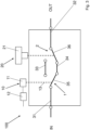
Figure 1 diagrammatically shows an example of the device according to the invention, in a first configuration; -
Figure 2 diagrammatically shows the device ofFigure 1 , in a second configuration; -
Figure 3 diagrammatically shows the device ofFigure 1 , in a third configuration; -
Figure 4 diagrammatically shows the device ofFigure 1 in a fourth configuration; -
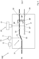
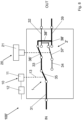
Figure 5 diagrammatically shows another example of the device according to the invention, in a first configuration; -
Figure 6 diagrammatically shows the device ofFigure 5 , in a second configuration; -
Figure 7 diagrammatically shows the device ofFigure 5 , in a third configuration; -
Figure 8 diagrammatically shows the device ofFigure 5 , in a fourth configuration; - The same elements, or functionally equivalent elements, have the same reference numeral.
- With reference to the Figures, exemplary and non-limiting embodiments of an electronic
electrical device 100, 100', or control device or mechatronic control device, according to the invention, are described. - In all the embodiments, the electronic
electrical device 100, 100' comprises - a first
electrical conductor 31 for the input of electric current; - a second
electrical conductor 32 for the output of electric current; - a first electrical control device 1 adapted to have two positions to electrically connect and disconnect the first
electrical conductor 31 and the secondelectrical conductor 32 to/from each other; - a second
electrical control device 2, 2' adapted to have two positions to electrically connect and disconnect the firstelectrical conductor 31 and the secondelectrical conductor 32 to/from each other; - first actuation means 10 comprising a digital
electronic controller 11; - second actuation means 20 comprising only mechanical and/or electromechanical components;
- wherein the first actuation means 10 are adapted to vary the position of said first electrical control device 1 independently of said second actuation means 20;
- and wherein the second actuation means 20 are adapted to vary the position of said second
electrical control device 2, 2' independently of said first actuation means 10. In particular, the first actuation means 10 and the second actuation means 20 are distinct from each other. - The first actuation means 10 are, preferably, adapted to vary the position only of said first electrical control device 1.
- The second actuation means 20 are, preferably, adapted to vary the position only of said second
electrical control device 2, 2'. - In an example (
Figure 1-4 ), the secondelectrical control device 2 is an electric diverter; and the electronicelectrical device 100 is configured to function as an electrical switch. - In particular, advantageously, the electronic
electrical device 100, depending on the position of the first electrical control device 1 and of the secondelectrical control device 2, may have two distinct configurations in which the electronicelectrical device 100 functions as a closed switch, and two distinct configurations in which the electronicelectrical device 100 functions as an open switch. - In another example (
Figure 5-8 ), said second electrical control device 2' is an electric inverter; and the electronic electrical device 100' is configured to function as an electric diverter. - In particular, the electronic electrical device 100' comprises a further
electrical conductor 39 for the output of electric current;
and the electronic electrical device 100' is configured so that, depending on the position taken by the first electrical control device 1 and by the second electrical control device 2' (i.e., by the electric inverter), the firstelectrical conductor 31 is electrically connected to the secondelectrical conductor 32 and electrically disconnected from said further electrical conductor 39 (Figure 5 andFigure 7 ), or the firstelectrical conductor 31 is electrically connected to said furtherelectrical conductor 39 and electrically disconnected from said second electrical conductor 32 (Figure 6 andFigure 8 ). - In particular, advantageously, the electronic electrical device 100', depending on the position of the first electrical control device 1 and of the second electrical control device 2', may have two distinct configurations in which the first
electrical conductor 31 is electrically connected to the secondelectrical conductor 32 and electrically disconnected from said furtherelectrical conductor 39, and two distinct configurations in which the firstelectrical conductor 31 is electrically connected to said furtherelectrical conductor 39 and electrically disconnected from said secondelectrical conductor 32. - In all the embodiments, preferably, the electronic
electrical device 100, 100' comprises a thirdelectrical conductor 33 and a fourthelectrical conductor 34. - Furthermore, said first electrical control device 1 comprises a fifth
electrical conductor 35 electrically connected to the firstelectrical conductor 31. - In a first position of the first electrical control device 1 the fifth
electrical conductor 35 is electrically connected to the thirdelectrical conductor 33 and electrically disconnected from the fourth electrical conductor 34 (Figure 1 ,Figure 4 ,Figure 5 ,Figure 8 ); - and in a second position of the first electrical control device 1, the fifth
electrical conductor 35 is electrically connected to the fourthelectrical conductor 34 and electrically disconnected from the third electrical conductor 33 (Figure 2 ,Figure 3 ,Figure 6 ,Figure 7 ). - In the example shown in
Figures 1-4 , the secondelectrical control device 2 comprises a sixthelectrical conductor 36 electrically connected to the secondelectrical conductor 32. - Furthermore, in a first position of the second
electrical control device 2 the sixthelectrical conductor 36 is electrically connected to the thirdelectrical conductor 33 and electrically disconnected from the fourth electrical conductor 34 (Figure 1 ,Figure 2 );
and in a second position of the secondelectrical control device 2 the sixthelectrical conductor 36 is electrically connected to the fourthelectrical conductor 34 and electrically disconnected from the third electrical conductor 33 (Figure 3 ,Figure 4 ). - Therefore, when the first electrical control device 1 is in the first position and the second
electrical control device 2 is in the first position, the firstelectrical conductor 31 and the secondelectrical conductor 32 are electrically connected to each other (Figure 1 ). - When the first electrical control device 1 is in the second position and the second
electrical control device 2 is in the first position, the firstelectrical conductor 31 and the secondelectrical conductor 32 are electrically disconnected from each other (Figure 2 ). - When the first electrical control device 1 is in the second position and the second
electrical control device 2 is in the second position, the firstelectrical conductor 31 and the secondelectrical conductor 32 are electrically connected to each other (Figure 3 ). - When the first electrical control device 1 is in the first position and the second
electrical control device 2 is in the second position, the firstelectrical conductor 31 and the secondelectrical conductor 32 are electrically disconnected from each other (Figure 4 ). - Advantageously, the fifth
electrical conductor 35 may be moved by the first actuation means 10 to be alternatively connected to theelectrical conductor 33 or to theelectrical conductor 34, independently of the second actuation means 20. - Advantageously, furthermore, the sixth
electrical conductor 36 may be moved by the second actuation means 20 to be alternatively connected to theelectrical conductor 33 or to theelectrical conductor 34, independently of the first actuation means 10. - In the example shown in
Figures 5-8 , the second electrical control device 2' comprises a sixth electrical conductor 36' electrically connected to the thirdelectrical conductor 33. - Furthermore, the second electrical control device 2' comprises a seventh electrical conductor 37' electrically connected to the fourth
electrical conductor 34. - In a first position of the second electrical control device 2' (
Figure 5 andFigure 7 ), the sixth electrical conductor 36' is electrically connected to the secondelectrical conductor 32 and electrically disconnected from said furtherelectrical conductor 39, and the seventh electrical conductor 37' is electrically connected to said furtherelectrical conductor 39 and electrically disconnected from said secondelectrical conductor 32. - In a second position of the second electrical control device 2' (
Figure 6 andFigure 8 ), the sixth electrical conductor 36' is electrically connected to said furtherelectrical conductor 39 and electrically disconnected from said secondelectrical conductor 32, and the seventh electrical conductor 37' is electrically connected to said secondelectrical conductor 32 and electrically disconnected from said furtherelectrical conductor 39. - The sixth electrical conductor 36' and the seventh electrical conductor 37' always move together.
- An electrical conductor 38' and an
electrical conductor 38" are also preferably provided. - The electrical conductor 38' is electrically connected to the
electrical conductor 32, in particular it branches off from theelectrical conductor 32. - The
electrical conductor 38" is electrically connected to theelectrical conductor 39, in particular it branches off from theelectrical conductor 39. - The electrical conductor 36' may be connected, alternatively, to a terminal of the
electrical conductor 32 or to a terminal of theelectrical conductor 38". - The electrical conductor 37' may be connected, alternatively, to a terminal of the
electrical conductor 39 or to a terminal of the electrical conductor 38'. - Advantageously, the electrical conductors 36', 37' may be moved by the second actuation means 20 independently of the first actuation means 10.
- In all the embodiments, said first electrical control device 1 is preferably an electric diverter.
- In all the embodiments, preferably said first actuation means 10 comprise one or more mechanical and/or
electromagnetic components 13, controlled by said digitalelectronic controller 11, connected to said first electrical control device 1, in particular to theelectrical conductor 35, to vary the position thereof; or said digitalelectronic controller 11 is configured to function as a digital electric diverter. - In all embodiments, preferably the electronic
electrical device 100, 100' comprises acommunication module 12 connected to said digitalelectronic controller 11. - The
communication module 12 is configured to communicate with a remote electronic control system (not shown), in particular in a wired manner and/or is configured to communicate with said remote electronic control system by means of Wi-Fi. In particular, thecommunication module 12 is configured to communicate with said remote electronic control system to receive a digital signal for changing the position of said first electrical control device 1. The remote electronic control system may be, exclusively by way of explanation and not by way of limitation, a computer, such as a tablet or a smartphone. - The
communication module 12 may be, for example, a BUS coupling unit. - By way of example and not by way of limitation, the digital
electronic controller 11 may communicate with said remote electronic control system by means of one or more of the following standards: the wired Konnex standard, the wired DALI standard, the Zig-Bee Wi-Fi standard, the Z-Wave Wi-Fi standard; a proprietary communication protocol. - In all the embodiments, preferably, said second actuation means 20 comprise a
button 21 or a lever, which may be manually operated by a user, and/or an electromagnet. - The button or lever is connected, in particular mechanically, to the second
electrical control device 2, 2', in particular to the electrical conductor 36 (Figure 1-4 ) and to the electrical conductors 36', 37' (Figure 5-8 ). - In particular, a pressure of the button, or a movement of the lever, causes the movement of the
electrical conductor 36. - A pressing of the button, or a movement of the lever, causes the movement of both electrical conductors 36', 37'.
- When an electromagnet is provided, the latter is adapted to move a moving part, and the electromagnet may be operated by means of an auxiliary electrical circuit external to the electronic
electrical device 100, 100'. - The electronic
electrical device 100, 100' may, for example, be configured to connect two portions of the electric power supply circuit to each other, in particular, to function as an electrical control switch. - The electronic
electrical device 100, 100' may also be configured to function as an electric control diverter in circuits having multiple control points. - For example, the electronic
electrical device 100, 100' may be configured to be arranged in a socket box or in a DIN rail. - The invention also relates to an electrical socket comprising an electronic
electrical device 100, 100'.
Claims (14)
- An electronic electrical device (100, 100'), comprising- a first electrical conductor (31) for the input of electric current;- a second electrical conductor (32) for the output of electric current;- a first electrical control device (1) adapted to have two positions to electrically connect and disconnect the first electrical conductor (31) and the second electrical conductor (32) to/from each other;- a second electrical control device (2, 2') adapted to have two positions to electrically connect and disconnect the first electrical conductor (31) and the second electrical conductor (32) to/from each other;- first actuation means (10);- second actuation means (20);wherein the first actuation means (10) are adapted to vary the position of said first electrical control device (1) independently of said second actuation means (20);and wherein the second actuation means (20) are adapted to vary the position of said second electrical control device (2, 2') independently of said first actuation means (10);characterized in thatthe first actuation means (10) comprise a digital electronic controller (11);and in that the second actuation means (20) comprise only mechanical and/or electromechanical components.
- An electronic electrical device (100) according to claim 1, wherein said second electrical control device (2) is an electric diverter; and wherein the electronic electrical device (100) is configured to function as an electrical switch.
- An electronic electrical device (100') according to claim 1, wherein said second electrical control device (2') is an electric inverter; and wherein the electronic electrical device (100') is configured to function as an electric diverter.
- An electronic electrical device (100') according to claim 3, comprising a further electrical conductor (39) for the output of electric current;
wherein the electronic electrical device (100') is configured so that, depending on the position taken by the first electrical control device (1) and by the second electrical control device (2'), the first electrical conductor (31) is electrically connected to the second electrical conductor (32) and electrically disconnected from said further electrical conductor (39), or the first electrical conductor (31) is electrically connected to said further electrical conductor (39) and electrically disconnected from said second electrical conductor (32). - An electronic electrical device (100, 100 ') according to any one of the preceding claims, comprising- a third electrical conductor (33);- a fourth electrical conductor (34);wherein said first electrical control device (1) comprises a fifth electrical conductor (35) electrically connected to the first electrical conductor (31);wherein in a first position of the first electrical control device (1) the fifth electrical conductor (35) is electrically connected to the third electrical conductor (33) and electrically disconnected from the fourth electrical conductor (34);wherein in a second position of the first electrical control device (1) the fifth electrical conductor (35) is electrically connected to the fourth electrical conductor (34) and electrically disconnected from the third electrical conductor (33).
- An electronic electrical device (100) according to claim 5 when it depends on claim 2,wherein the second electrical control device (2) comprises a sixth electrical conductor (36) electrically connected to the second electrical conductor (32);wherein in a first position of the second electrical control device (2) the sixth electrical conductor (36) is electrically connected to the third electrical conductor (33) and electrically disconnected from the fourth electrical conductor (34);wherein in a second position of the second electrical control device (2) the sixth electrical conductor (36) is electrically connected to the fourth electrical conductor (34) and electrically disconnected from the third electrical conductor (33).
- An electronic electrical device (100') according to claim 5 when it depends on claim 4,wherein the second electrical control device (2') comprises a sixth electrical conductor (36') electrically connected to the third electrical conductor (33);wherein the second electrical control device (2') comprises a seventh electrical conductor (37') electrically connected to the fourth electrical conductor (34);wherein in a first position of the second electrical control device (2'), the sixth electrical conductor (36') is electrically connected to the second electrical conductor (32) and electrically disconnected from said further electrical conductor (39), and the seventh electrical conductor (37') is electrically connected to said further electrical conductor (39) and electrically disconnected from said second electrical conductor (32);wherein in a second position of the second electrical control device (2'), the sixth electrical conductor (36') is electrically connected to said further electrical conductor (39) and electrically disconnected from said second electrical conductor (32), and the seventh electrical conductor (37') is electrically connected to said second electrical conductor (32) and electrically disconnected from said further electrical conductor (39).
- An electronic electrical device (100, 100') according to any one of the preceding claims, wherein said first electrical control device (1) is an electric diverter.
- An electronic electrical device (100, 100') according to any one of the preceding claims, wherein said first actuation means (10) comprise one or more mechanical and/or electromagnetic components (13), controlled by said digital electronic controller (11), connected to said first electrical control device (1) to vary the position thereof; or wherein said digital electronic controller (11) is configured to function as a digital electric diverter.
- An electronic electrical device (100, 100') according to any one of the preceding claims, comprising a communication module (12) connected to said digital electronic controller (11),
wherein the communication module (12) is configured to communicate with a remote electronic control system in a wired manner and/or to communicate with said remote electronic control system by means of Wi-Fi, to receive a digital signal to change the position of said first electrical control device (1). - An electronic electrical device (100, 100') according to any one of the preceding claims, wherein said second actuation means (20) comprise a button (21) or a lever, manually operable by a user, and/or an electromagnet.
- An electronic electrical device (100, 100') according to any one of the preceding claims, configured to connect two portions of an electric power supply circuit to each other.
- An electronic electrical device (100, 100') according to any one of the preceding claims, configured to be arranged in a socket box or in a DIN rail.
- An electrical socket, in particular a controlled electrical socket, comprising an electronic electrical device (100, 100') according to any one of claims 1 to 11.
Applications Claiming Priority (2)
| Application Number | Priority Date | Filing Date | Title |
|---|---|---|---|
| IT102021000011870A IT202100011870A1 (en) | 2021-05-10 | 2021-05-10 | MECHATRONIC CONTROL DEVICE |
| PCT/IB2022/054264 WO2022238856A1 (en) | 2021-05-10 | 2022-05-09 | Mechatronic control device |
Publications (2)
| Publication Number | Publication Date |
|---|---|
| EP4338187A1 EP4338187A1 (en) | 2024-03-20 |
| EP4338187B1 true EP4338187B1 (en) | 2025-04-16 |
Family
ID=77022068
Family Applications (1)
| Application Number | Title | Priority Date | Filing Date |
|---|---|---|---|
| EP22727436.2A Active EP4338187B1 (en) | 2021-05-10 | 2022-05-09 | Mechatronic control device |
Country Status (5)
| Country | Link |
|---|---|
| US (1) | US12400808B2 (en) |
| EP (1) | EP4338187B1 (en) |
| ES (1) | ES3032240T3 (en) |
| IT (1) | IT202100011870A1 (en) |
| WO (1) | WO2022238856A1 (en) |
Families Citing this family (1)
| Publication number | Priority date | Publication date | Assignee | Title |
|---|---|---|---|---|
| IT202100011870A1 (en) * | 2021-05-10 | 2022-11-10 | Univ Degli Studi Roma La Sapienza | MECHATRONIC CONTROL DEVICE |
Family Cites Families (35)
| Publication number | Priority date | Publication date | Assignee | Title |
|---|---|---|---|---|
| US3867598A (en) * | 1973-10-09 | 1975-02-18 | Westinghouse Electric Corp | Control switch |
| CA1112698A (en) * | 1978-03-08 | 1981-11-17 | Friedrich J.A. Kourimsky | Pivotally actuated roller-type contact electrical switch |
| GB2125627B (en) * | 1982-08-18 | 1986-07-02 | Otehall Limited | Electric switches |
| DE3240547A1 (en) * | 1982-11-03 | 1984-06-14 | Diehl Gmbh & Co | CIRCUIT ARRANGEMENT FOR SWITCHING THE POWER SUPPLY TO ELECTRICAL CONSUMERS |
| FR2651915B1 (en) * | 1989-09-13 | 1991-11-08 | Merlin Gerin | ULTRA-FAST STATIC CIRCUIT BREAKER WITH GALVANIC ISOLATION. |
| US5180051A (en) * | 1991-06-28 | 1993-01-19 | Square D Company | Remote control circuit breaker |
| US5301083A (en) * | 1991-09-30 | 1994-04-05 | Eaton Corporation | Remote control residential circuit breaker |
| US5408208A (en) * | 1992-10-22 | 1995-04-18 | Siemens Energy & Automation, Inc. | Electrically tripped mechanism for knife blade switches |
| DE4304367C2 (en) * | 1993-02-13 | 2000-12-07 | Diehl Stiftung & Co | Mountable switch |
| FR2799572B1 (en) * | 1999-10-11 | 2001-12-21 | Schneider Electric Ind Sa | CONTACTOR-CIRCUIT-BREAKER |
| ITRM20010116A1 (en) * | 2001-03-05 | 2002-09-05 | Univ Roma | GONIOMETRIC-ASTRONOMIC INDICATOR, IN PARTICULAR SOLAR AND / OR MOON. |
| US6753493B2 (en) * | 2001-06-01 | 2004-06-22 | Hubbell Incorporated | Electrical circuit interrupting device |
| US6701236B2 (en) * | 2001-10-19 | 2004-03-02 | Yamaha Hatsudoki Kabushiki Kaisha | Intelligent mechatronic control suspension system based on soft computing |
| US20040024750A1 (en) * | 2002-07-31 | 2004-02-05 | Ulyanov Sergei V. | Intelligent mechatronic control suspension system based on quantum soft computing |
| WO2005041464A2 (en) * | 2003-10-24 | 2005-05-06 | Face Bradbury R | Self-powered, electronic keyed, multifunction switching system |
| NL1025523C2 (en) * | 2004-02-19 | 2005-08-22 | Iku Holding Montfoort Bv | Mechatronic control system. |
| US7280337B2 (en) * | 2004-08-05 | 2007-10-09 | Eaton Corporation | Circuit breaker including a non-mechanical, electronic status or control circuit |
| DE202004012469U1 (en) * | 2004-08-10 | 2006-01-19 | Ellenberger & Poensgen Gmbh | Breaker arrangement |
| DE102011003598B4 (en) * | 2011-02-03 | 2023-02-02 | Siemens Aktiengesellschaft | Electronic trip unit for an electric switch |
| DE102012005474A1 (en) * | 2012-03-17 | 2013-09-19 | Abb Ag | Input device of the electrical installation technology with rotary control |
| EP2682971B1 (en) * | 2012-07-03 | 2016-11-30 | ABB Schweiz AG | A device for indicating the state of a switching apparatus |
| CN102809680B (en) * | 2012-08-27 | 2015-01-21 | 北京四方继保自动化股份有限公司 | Anti-interference switching value transmission circuit |
| EP3102444B1 (en) * | 2014-01-28 | 2021-03-03 | Università degli Studi di Roma "La Sapienza" | Vehicle suspension with adjustment of vibration damping force |
| ES2690723T3 (en) * | 2014-05-16 | 2018-11-22 | Universita' Degli Studi Di Roma "La Sapienza" | Echo-scintigraphic probe for medical applications and related diagnostic method |
| JP6434851B2 (en) * | 2015-04-13 | 2018-12-05 | アルプス電気株式会社 | Input device |
| DE102015225243A1 (en) * | 2015-06-24 | 2016-12-29 | Siemens Aktiengesellschaft | Electric switch |
| ITUA20163673A1 (en) * | 2016-05-23 | 2017-11-23 | Hike S R L | Electrical control device, particularly for home automation systems. |
| EP3312861B1 (en) * | 2016-10-24 | 2021-02-24 | C&K Components SAS | Electrical pushbutton snap switch with means for identifying the position of the driving member and of the pushbutton |
| FR3074926B1 (en) * | 2017-12-07 | 2019-11-29 | Ixblue | METHOD OF OPTIMIZING THE PERFORMANCE OF A MECHATRONIC SYSTEM SERVICING, DEVICE ADAPTED |
| US11264191B2 (en) * | 2018-06-15 | 2022-03-01 | Mitsubishi Electric Corporation | Breaker |
| US11373831B2 (en) * | 2019-05-18 | 2022-06-28 | Amber Solutions, Inc. | Intelligent circuit breakers |
| US20220334541A1 (en) * | 2019-06-26 | 2022-10-20 | Hike S.R.L. | Electrical control apparatus, particularly for home automation systems |
| US20220305012A1 (en) * | 2019-06-26 | 2022-09-29 | Eisai R&D Management Co., Ltd. | Lemborexant for treating sleep issues |
| US11158473B2 (en) * | 2019-07-03 | 2021-10-26 | Eaton Intelligent Power Limited | Solid state circuit breaker button interlocking system |
| IT202100011870A1 (en) * | 2021-05-10 | 2022-11-10 | Univ Degli Studi Roma La Sapienza | MECHATRONIC CONTROL DEVICE |
-
2021
- 2021-05-10 IT IT102021000011870A patent/IT202100011870A1/en unknown
-
2022
- 2022-05-09 EP EP22727436.2A patent/EP4338187B1/en active Active
- 2022-05-09 WO PCT/IB2022/054264 patent/WO2022238856A1/en not_active Ceased
- 2022-05-09 US US18/289,549 patent/US12400808B2/en active Active
- 2022-05-09 ES ES22727436T patent/ES3032240T3/en active Active
Also Published As
| Publication number | Publication date |
|---|---|
| ES3032240T3 (en) | 2025-07-16 |
| EP4338187A1 (en) | 2024-03-20 |
| US12400808B2 (en) | 2025-08-26 |
| IT202100011870A1 (en) | 2022-11-10 |
| WO2022238856A1 (en) | 2022-11-17 |
| US20240249894A1 (en) | 2024-07-25 |
Similar Documents
| Publication | Publication Date | Title |
|---|---|---|
| US6545374B1 (en) | Power transfer device installable in a power meter receptacle | |
| US9069335B2 (en) | Emergency stop module arrangement | |
| CN114336292B (en) | Modularized low-voltage power distribution module | |
| US12400808B2 (en) | Mechatronic control device | |
| GB2452138A (en) | Power converter for vehicle | |
| CA2519454A1 (en) | Low-voltage module | |
| US9407071B2 (en) | Accessory device assembly for low and medium voltage switching devices | |
| CN111010212B (en) | Accessories for low and medium voltage switchgear, switchgear and distribution networks | |
| US8035256B2 (en) | Switching device and a system comprising the same | |
| US11784443B2 (en) | Multifunctional carrier and high voltage contactor for a battery system of an electric vehicle | |
| US11749485B2 (en) | Modular switch apparatus for controlling at least one electric drive | |
| CN218825290U (en) | Detection apparatus for circuit breaker controller | |
| CN209071157U (en) | A kind of switch | |
| CN202600387U (en) | Assembly for controlling effectors | |
| EP0112311B1 (en) | A method for accomplishing a time relay function, and a device for utilization of the method | |
| US20180261407A1 (en) | Three-way switch | |
| RU2806474C1 (en) | Charging station control unit | |
| CN220774934U (en) | Adapter plate | |
| EP4024433B1 (en) | Universal control module for a reversing contactor and method of using it | |
| CN210199533U (en) | Load control device and wireless load control system | |
| CN101785077A (en) | Devices for controlling motor-driven switching gears for switchgear | |
| CN115548797A (en) | A parallel double socket power supply connection device and double socket module | |
| CN122052306A (en) | Method and device for remotely controlling regional power failure of machine room | |
| JP2024002068A (en) | Auxiliary relay adapter | |
| CN103871788A (en) | Electric switching apparatus |
Legal Events
| Date | Code | Title | Description |
|---|---|---|---|
| STAA | Information on the status of an ep patent application or granted ep patent |
Free format text: STATUS: UNKNOWN |
|
| STAA | Information on the status of an ep patent application or granted ep patent |
Free format text: STATUS: THE INTERNATIONAL PUBLICATION HAS BEEN MADE |
|
| PUAI | Public reference made under article 153(3) epc to a published international application that has entered the european phase |
Free format text: ORIGINAL CODE: 0009012 |
|
| STAA | Information on the status of an ep patent application or granted ep patent |
Free format text: STATUS: REQUEST FOR EXAMINATION WAS MADE |
|
| 17P | Request for examination filed |
Effective date: 20231204 |
|
| AK | Designated contracting states |
Kind code of ref document: A1 Designated state(s): AL AT BE BG CH CY CZ DE DK EE ES FI FR GB GR HR HU IE IS IT LI LT LU LV MC MK MT NL NO PL PT RO RS SE SI SK SM TR |
|
| P01 | Opt-out of the competence of the unified patent court (upc) registered |
Effective date: 20240321 |
|
| DAV | Request for validation of the european patent (deleted) | ||
| DAX | Request for extension of the european patent (deleted) | ||
| GRAP | Despatch of communication of intention to grant a patent |
Free format text: ORIGINAL CODE: EPIDOSNIGR1 |
|
| STAA | Information on the status of an ep patent application or granted ep patent |
Free format text: STATUS: GRANT OF PATENT IS INTENDED |
|
| INTG | Intention to grant announced |
Effective date: 20241108 |
|
| GRAS | Grant fee paid |
Free format text: ORIGINAL CODE: EPIDOSNIGR3 |
|
| GRAA | (expected) grant |
Free format text: ORIGINAL CODE: 0009210 |
|
| STAA | Information on the status of an ep patent application or granted ep patent |
Free format text: STATUS: THE PATENT HAS BEEN GRANTED |
|
| AK | Designated contracting states |
Kind code of ref document: B1 Designated state(s): AL AT BE BG CH CY CZ DE DK EE ES FI FR GB GR HR HU IE IS IT LI LT LU LV MC MK MT NL NO PL PT RO RS SE SI SK SM TR |
|
| REG | Reference to a national code |
Ref country code: GB Ref legal event code: FG4D |
|
| REG | Reference to a national code |
Ref country code: CH Ref legal event code: EP Ref country code: DE Ref legal event code: R096 Ref document number: 602022013273 Country of ref document: DE |
|
| REG | Reference to a national code |
Ref country code: IE Ref legal event code: FG4D |
|
| PGFP | Annual fee paid to national office [announced via postgrant information from national office to epo] |
Ref country code: DE Payment date: 20250603 Year of fee payment: 4 |
|
| REG | Reference to a national code |
Ref country code: ES Ref legal event code: FG2A Ref document number: 3032240 Country of ref document: ES Kind code of ref document: T3 Effective date: 20250716 |
|
| PGFP | Annual fee paid to national office [announced via postgrant information from national office to epo] |
Ref country code: FR Payment date: 20250603 Year of fee payment: 4 |
|
| PGFP | Annual fee paid to national office [announced via postgrant information from national office to epo] |
Ref country code: AT Payment date: 20250721 Year of fee payment: 4 |
|
| REG | Reference to a national code |
Ref country code: NL Ref legal event code: MP Effective date: 20250416 |
|
| PG25 | Lapsed in a contracting state [announced via postgrant information from national office to epo] |
Ref country code: NL Free format text: LAPSE BECAUSE OF FAILURE TO SUBMIT A TRANSLATION OF THE DESCRIPTION OR TO PAY THE FEE WITHIN THE PRESCRIBED TIME-LIMIT Effective date: 20250416 |
|
| REG | Reference to a national code |
Ref country code: AT Ref legal event code: MK05 Ref document number: 1786377 Country of ref document: AT Kind code of ref document: T Effective date: 20250416 |
|
| PG25 | Lapsed in a contracting state [announced via postgrant information from national office to epo] |
Ref country code: FI Free format text: LAPSE BECAUSE OF FAILURE TO SUBMIT A TRANSLATION OF THE DESCRIPTION OR TO PAY THE FEE WITHIN THE PRESCRIBED TIME-LIMIT Effective date: 20250416 Ref country code: PT Free format text: LAPSE BECAUSE OF FAILURE TO SUBMIT A TRANSLATION OF THE DESCRIPTION OR TO PAY THE FEE WITHIN THE PRESCRIBED TIME-LIMIT Effective date: 20250818 |
|
| PGFP | Annual fee paid to national office [announced via postgrant information from national office to epo] |
Ref country code: ES Payment date: 20250812 Year of fee payment: 4 |
|
| REG | Reference to a national code |
Ref country code: LT Ref legal event code: MG9D |
|
| PG25 | Lapsed in a contracting state [announced via postgrant information from national office to epo] |
Ref country code: NO Free format text: LAPSE BECAUSE OF FAILURE TO SUBMIT A TRANSLATION OF THE DESCRIPTION OR TO PAY THE FEE WITHIN THE PRESCRIBED TIME-LIMIT Effective date: 20250716 Ref country code: GR Free format text: LAPSE BECAUSE OF FAILURE TO SUBMIT A TRANSLATION OF THE DESCRIPTION OR TO PAY THE FEE WITHIN THE PRESCRIBED TIME-LIMIT Effective date: 20250717 |
|
| PG25 | Lapsed in a contracting state [announced via postgrant information from national office to epo] |
Ref country code: PL Free format text: LAPSE BECAUSE OF FAILURE TO SUBMIT A TRANSLATION OF THE DESCRIPTION OR TO PAY THE FEE WITHIN THE PRESCRIBED TIME-LIMIT Effective date: 20250416 |
|
| PG25 | Lapsed in a contracting state [announced via postgrant information from national office to epo] |
Ref country code: BG Free format text: LAPSE BECAUSE OF FAILURE TO SUBMIT A TRANSLATION OF THE DESCRIPTION OR TO PAY THE FEE WITHIN THE PRESCRIBED TIME-LIMIT Effective date: 20250416 |
|
| PG25 | Lapsed in a contracting state [announced via postgrant information from national office to epo] |
Ref country code: HR Free format text: LAPSE BECAUSE OF FAILURE TO SUBMIT A TRANSLATION OF THE DESCRIPTION OR TO PAY THE FEE WITHIN THE PRESCRIBED TIME-LIMIT Effective date: 20250416 Ref country code: AT Free format text: LAPSE BECAUSE OF FAILURE TO SUBMIT A TRANSLATION OF THE DESCRIPTION OR TO PAY THE FEE WITHIN THE PRESCRIBED TIME-LIMIT Effective date: 20250416 |
|
| PG25 | Lapsed in a contracting state [announced via postgrant information from national office to epo] |
Ref country code: RS Free format text: LAPSE BECAUSE OF FAILURE TO SUBMIT A TRANSLATION OF THE DESCRIPTION OR TO PAY THE FEE WITHIN THE PRESCRIBED TIME-LIMIT Effective date: 20250716 |
|
| PGFP | Annual fee paid to national office [announced via postgrant information from national office to epo] |
Ref country code: RO Payment date: 20250711 Year of fee payment: 4 |
|
| PG25 | Lapsed in a contracting state [announced via postgrant information from national office to epo] |
Ref country code: IS Free format text: LAPSE BECAUSE OF FAILURE TO SUBMIT A TRANSLATION OF THE DESCRIPTION OR TO PAY THE FEE WITHIN THE PRESCRIBED TIME-LIMIT Effective date: 20250816 |
|
| PG25 | Lapsed in a contracting state [announced via postgrant information from national office to epo] |
Ref country code: LV Free format text: LAPSE BECAUSE OF FAILURE TO SUBMIT A TRANSLATION OF THE DESCRIPTION OR TO PAY THE FEE WITHIN THE PRESCRIBED TIME-LIMIT Effective date: 20250416 |
|
| REG | Reference to a national code |
Ref country code: CH Ref legal event code: H13 Free format text: ST27 STATUS EVENT CODE: U-0-0-H10-H13 (AS PROVIDED BY THE NATIONAL OFFICE) Effective date: 20251223 |
|
| PG25 | Lapsed in a contracting state [announced via postgrant information from national office to epo] |
Ref country code: DK Free format text: LAPSE BECAUSE OF FAILURE TO SUBMIT A TRANSLATION OF THE DESCRIPTION OR TO PAY THE FEE WITHIN THE PRESCRIBED TIME-LIMIT Effective date: 20250416 Ref country code: SM Free format text: LAPSE BECAUSE OF FAILURE TO SUBMIT A TRANSLATION OF THE DESCRIPTION OR TO PAY THE FEE WITHIN THE PRESCRIBED TIME-LIMIT Effective date: 20250416 |
|
| PG25 | Lapsed in a contracting state [announced via postgrant information from national office to epo] |
Ref country code: LU Free format text: LAPSE BECAUSE OF NON-PAYMENT OF DUE FEES Effective date: 20250509 |
|
| PG25 | Lapsed in a contracting state [announced via postgrant information from national office to epo] |
Ref country code: CH Free format text: LAPSE BECAUSE OF NON-PAYMENT OF DUE FEES Effective date: 20250531 |
|
| REG | Reference to a national code |
Ref country code: DE Ref legal event code: R097 Ref document number: 602022013273 Country of ref document: DE |
|
| PG25 | Lapsed in a contracting state [announced via postgrant information from national office to epo] |
Ref country code: CZ Free format text: LAPSE BECAUSE OF FAILURE TO SUBMIT A TRANSLATION OF THE DESCRIPTION OR TO PAY THE FEE WITHIN THE PRESCRIBED TIME-LIMIT Effective date: 20250416 |
|
| PG25 | Lapsed in a contracting state [announced via postgrant information from national office to epo] |
Ref country code: EE Free format text: LAPSE BECAUSE OF FAILURE TO SUBMIT A TRANSLATION OF THE DESCRIPTION OR TO PAY THE FEE WITHIN THE PRESCRIBED TIME-LIMIT Effective date: 20250416 |
|
| PG25 | Lapsed in a contracting state [announced via postgrant information from national office to epo] |
Ref country code: SK Free format text: LAPSE BECAUSE OF FAILURE TO SUBMIT A TRANSLATION OF THE DESCRIPTION OR TO PAY THE FEE WITHIN THE PRESCRIBED TIME-LIMIT Effective date: 20250416 |
|
| PG25 | Lapsed in a contracting state [announced via postgrant information from national office to epo] |
Ref country code: IT Free format text: LAPSE BECAUSE OF FAILURE TO SUBMIT A TRANSLATION OF THE DESCRIPTION OR TO PAY THE FEE WITHIN THE PRESCRIBED TIME-LIMIT Effective date: 20250416 |
|
| REG | Reference to a national code |
Ref country code: BE Ref legal event code: MM Effective date: 20250531 |
|
| PG25 | Lapsed in a contracting state [announced via postgrant information from national office to epo] |
Ref country code: MC Free format text: LAPSE BECAUSE OF FAILURE TO SUBMIT A TRANSLATION OF THE DESCRIPTION OR TO PAY THE FEE WITHIN THE PRESCRIBED TIME-LIMIT Effective date: 20250416 |
|
| PLBE | No opposition filed within time limit |
Free format text: ORIGINAL CODE: 0009261 |
|
| STAA | Information on the status of an ep patent application or granted ep patent |
Free format text: STATUS: NO OPPOSITION FILED WITHIN TIME LIMIT |
|
| REG | Reference to a national code |
Ref country code: CH Ref legal event code: L10 Free format text: ST27 STATUS EVENT CODE: U-0-0-L10-L00 (AS PROVIDED BY THE NATIONAL OFFICE) Effective date: 20260225 |
|
| 26N | No opposition filed |
Effective date: 20260119 |
|
| PG25 | Lapsed in a contracting state [announced via postgrant information from national office to epo] |
Ref country code: IE Free format text: LAPSE BECAUSE OF NON-PAYMENT OF DUE FEES Effective date: 20250509 |
|
| PG25 | Lapsed in a contracting state [announced via postgrant information from national office to epo] |
Ref country code: BE Free format text: LAPSE BECAUSE OF NON-PAYMENT OF DUE FEES Effective date: 20250531 |