EP4337424B1 - Power tool - Google Patents
Power tool Download PDFInfo
- Publication number
- EP4337424B1 EP4337424B1 EP22722162.9A EP22722162A EP4337424B1 EP 4337424 B1 EP4337424 B1 EP 4337424B1 EP 22722162 A EP22722162 A EP 22722162A EP 4337424 B1 EP4337424 B1 EP 4337424B1
- Authority
- EP
- European Patent Office
- Prior art keywords
- frame
- adapter
- unit
- power tool
- handle
- Prior art date
- Legal status (The legal status is an assumption and is not a legal conclusion. Google has not performed a legal analysis and makes no representation as to the accuracy of the status listed.)
- Active
Links
Images


Classifications
-
- B—PERFORMING OPERATIONS; TRANSPORTING
- B25—HAND TOOLS; PORTABLE POWER-DRIVEN TOOLS; MANIPULATORS
- B25F—COMBINATION OR MULTI-PURPOSE TOOLS NOT OTHERWISE PROVIDED FOR; DETAILS OR COMPONENTS OF PORTABLE POWER-DRIVEN TOOLS NOT PARTICULARLY RELATED TO THE OPERATIONS PERFORMED AND NOT OTHERWISE PROVIDED FOR
- B25F5/00—Details or components of portable power-driven tools not particularly related to the operations performed and not otherwise provided for
- B25F5/02—Construction of casings, bodies or handles
-
- B—PERFORMING OPERATIONS; TRANSPORTING
- B25—HAND TOOLS; PORTABLE POWER-DRIVEN TOOLS; MANIPULATORS
- B25B—TOOLS OR BENCH DEVICES NOT OTHERWISE PROVIDED FOR, FOR FASTENING, CONNECTING, DISENGAGING, OR HOLDING
- B25B21/00—Portable power-driven screw or nut setting or loosening tools; Attachments for drilling apparatus serving the same purpose
-
- B—PERFORMING OPERATIONS; TRANSPORTING
- B25—HAND TOOLS; PORTABLE POWER-DRIVEN TOOLS; MANIPULATORS
- B25F—COMBINATION OR MULTI-PURPOSE TOOLS NOT OTHERWISE PROVIDED FOR; DETAILS OR COMPONENTS OF PORTABLE POWER-DRIVEN TOOLS NOT PARTICULARLY RELATED TO THE OPERATIONS PERFORMED AND NOT OTHERWISE PROVIDED FOR
- B25F5/00—Details or components of portable power-driven tools not particularly related to the operations performed and not otherwise provided for
- B25F5/006—Vibration damping means
-
- B—PERFORMING OPERATIONS; TRANSPORTING
- B25—HAND TOOLS; PORTABLE POWER-DRIVEN TOOLS; MANIPULATORS
- B25G—HANDLES FOR HAND IMPLEMENTS
- B25G1/00—Handle constructions
- B25G1/10—Handle constructions characterised by material or shape
-
- B—PERFORMING OPERATIONS; TRANSPORTING
- B25—HAND TOOLS; PORTABLE POWER-DRIVEN TOOLS; MANIPULATORS
- B25G—HANDLES FOR HAND IMPLEMENTS
- B25G1/00—Handle constructions
- B25G1/10—Handle constructions characterised by material or shape
- B25G1/12—Handle constructions characterised by material or shape electrically insulating material
-
- H—ELECTRICITY
- H01—ELECTRIC ELEMENTS
- H01M—PROCESSES OR MEANS, e.g. BATTERIES, FOR THE DIRECT CONVERSION OF CHEMICAL ENERGY INTO ELECTRICAL ENERGY
- H01M50/00—Constructional details or processes of manufacture of the non-active parts of electrochemical cells other than fuel cells, e.g. hybrid cells
- H01M50/20—Mountings; Secondary casings or frames; Racks, modules or packs; Suspension devices; Shock absorbers; Transport or carrying devices; Holders
- H01M50/218—Mountings; Secondary casings or frames; Racks, modules or packs; Suspension devices; Shock absorbers; Transport or carrying devices; Holders characterised by the material
- H01M50/22—Mountings; Secondary casings or frames; Racks, modules or packs; Suspension devices; Shock absorbers; Transport or carrying devices; Holders characterised by the material of the casings or racks
-
- H—ELECTRICITY
- H05—ELECTRIC TECHNIQUES NOT OTHERWISE PROVIDED FOR
- H05K—PRINTED CIRCUITS; CASINGS OR CONSTRUCTIONAL DETAILS OF ELECTRIC APPARATUS; MANUFACTURE OF ASSEMBLAGES OF ELECTRICAL COMPONENTS
- H05K9/00—Screening of apparatus or components against electric or magnetic fields
- H05K9/0007—Casings
Definitions
- the invention relates to the field of power tools such as for example pistol tools or other handheld tools for assembly lines and industrial applications.
- the invention also relates to the field of power tools in general even for hobby and building related applications.
- EMC electromagnetic compatibility
- ESD electrostatic discharge
- power tools are today grounded via a cable if they are cable connected tools or they are grounded when connected to a controller that is close to the assembly area, which controller has ground level and therewith provides the same ground level to the tool.
- connection or interface between handle and battery adapter and battery, respectively is rather rigid and stiff.
- the power tool thus gets an impact, for example due to falling to the ground, it tends to break at the interface or intersection battery adapter and battery, respectively, and handle.
- An object of the present invention is therefore to provide an improved power tool.
- Another object of the present invention is to provide a power tool such as a pistol tool that is reliable, robust and easy to assemble.
- a power tool having a battery unit, a handle unit and a motor unit
- the handle unit comprises a frame that interconnects the battery unit with the motor unit.
- the frame is thereby made of an electrically conductive material that is strong and robust, such as for example aluminum or conductive fibre, such as metal fibre, reinforced plastic.
- the advantage of such as solution is that the PCBs, the controller, the cables, the antenna, the communication unit and other components can be assembled to the frame and not into a handle shell. This leads to a cleanly assembled power tool that has the same ground level over the entire tool.
- the adapter By providing an adapter between the frame and the battery unit, which adapter is capable of absorbing shocks and impacts, whereby the adapter is also made of an electrically conductive material such as aluminum, steel or metal fibre, reinforced plastic, it is further possible to make the power tool resistant to destruction at the handle - battery unit interface.
- the inventor has further realized that this resistance to destruction can further be increased when inner handle covers and outer handle covers with different amounts of glass fibres embedded in plastic are provided, whereby the inner handle covers are made less stiff than the outer handle covers.
- a power tool for example a pistol tool or any other hand held power tool comprising a motor unit comprising a motor and a drive axle connected to the motor, a battery unit configured to receive a battery and a handle unit interconnecting the motor unit and the battery unit, the handle unit comprising:
- the frame provides a basis for the mounting of all other components in the handle and at the same time the frame provides one and the same ground level across the entire tool from the motor unit to the battery unit and the battery when the battery is coupled.
- the frame serves as mounting platform for the other components in the handle unit.
- the frame provides the basis for mounting the components one of the outer handle cover can be removed and all the components stay cleanly and neatly in place, which facilitates maintenance and repair of the pistol tool.
- the frame may be made of a metal such as aluminium, steel or titan or of an electrically conductive fibre reinforced plastic.
- the handle unit comprises an adapter that is connected to the frame and the battery unit, whereby the adapter is electrically conductive and designed to have shock absorbing capabilities.
- the adapter may be integrally formed with the frame or the battery unit or both.
- the adapter helps to reduce the risk of a pistol tool breaking at the interface handle unit - battery unit in case of a fall for instance.
- the adapter may also be made of a metal such as aluminium, steel or titan or electrically conductive fibre reinforced plastic.
- the adapter may comprise a longitudinal web and at least one arch-shaped element connected to the longitudinal web and the adapter may comprise an electrically conductive adapter - battery unit fastening mechanism and an electrically conductive adapter - frame fastening mechanism.
- the above design of the adapter helps to improve the shock absorbing properties of the adapter and ensures a good and reliable connection to the handle unit and the battery unit, respectively.
- the adapter may comprise two arch-shaped elements and one web or two webs and two arch-shaped elements for improved stability and reliability.
- the frame may comprise a frame - motor unit fastening mechanism and a frame - adapter fastening mechanism, wherein the frame - motor unit fastening mechanism and the frame - adapter fastening mechanism are electrically conductive, said mechanisms being used for connecting the frame to the motor unit and the adapter and therewith the battery unit.
- fastening mechanisms provide a reliable and strong connection between handle unit and motor unit and handle unit and battery unit and adapter, respectively.
- the fastening mechanisms are electrically conductive for providing one and the same ground level across the entire pistol tool.
- the handle unit further may further comprise a pair of inner handle covers configured to be arranged around the frame and printed circuit board and configured to be arranged on an inner side of the pair of outer handle covers.
- the pair of inner handle covers may further improve the shock resistance of the pistol tool.
- the amount of glass fibres is chosen to be less in percentage by weight as in the pair of outer handle covers, then the distribution of the shock or load is improved in case of an impact, since the pair of inner handle covers are allowed to be deformed with less force or shock than the pair of outer handle covers which leads to an optimized load distribution and therewith a higher shock resistance.
- the frame may further comprise a bolt opening configured to receive a bolt for fastening the printed circuit board and the pair of inner handle covers, the bolt being made of electrically conductive material and configured to physically touch the printed circuit board.
- the bold may be advantageous for a clean and robust assembly at the same time it may provide grounding to the printed circuit board.
- This grounding may alternatively be provided via an electrically conductive sleeve that is arranged around the bolt.
- At least one of the pair of inner handle covers comprises a channel for receiving and embedding cables.
- the frame may comprise a receiving cavity for mounting the control button.
- Such a receiving cavity facilitates the replacement of the control button in case it breaks.
- the control button and its trigger may be fastened via a splint or the like in a trigger adapter, which is embedded via a spring in the receiving cavity. Removing the splint will allow to easily replace the control button.
- Other solutions may of course be used but the receiving cavity also facilitates assembly of the control button.
- the handle unit may further comprise an insulation and protection element that is connected to the frame in between the frame and the printed circuit board.
- This insulation and protection element may be made of an electrically insulating and rather soft material so that it can protect the printed circuit board and other sensitive electric components from electric discharges or shocks or the like.
- the outer handle cover may extend from the motor unit to the battery unit.
- This provides for a stable covering of the handle unit.
- electrically conductive and strong material generally means either some type of metal such as aluminium, steel, titan or an alloy thereof or fibre reinforced plastic, whereby the fibres may be electrically conductive carbon fibres or metal fibres.
- fastening mechanism refers generally to thread, bolt, hole and screw combinations for fastening components to one another.
- Other fastening mechanisms such as form fit or force fit connections and even adhesive induced connections or electrically conductive adhesive induced connections are covered by this term.
- FIG 1 illustrates a pistol tool 1 having a motor unit 2, handle unit 4 and a battery unit 6.
- the pistol tool 1 is shown without a battery, it is however clear that a battery can be coupled to the battery unit 6.
- the motor unit 2 comprises a motor housing 12 and a motor 10 (c.f. figure 2 ).
- the motor 10 is driving a drive axle 38 (c.f. figure 2 ) having a bit connector 40.
- the handle unit 4 comprises a reverse button 28 to change the rotational direction of the motor and therewith the axle 38 and the bit connector 40, respectively.
- handle unit 4 further comprises a control button 26 with a trigger 62 and a pair of outer handle covers 14 arranged to cover the handle unit 4.
- the pair of outer handle covers 14 extend from the motor unit 2 to the battery unit 6 and are fastened to the motor unit 2 and the battery unit 6 via an outer handle cover fastening mechanism 72, as shown in figure 2 .
- the outer handle cover fastening mechanism 72 comprises of a thread-hole, screw bolt and hole combination as illustrated in figures 1 and 2 .
- FIG 2 shows the same pistol tool 1 as figure 1 but with removed front cap and bit adapter and also with a removed, left, outer handle cover 14.
- the pair of outer handle covers 14 each comprise a reverse button recess 46 that extends through the outer handle covers 14.
- the reverse button recess 46 is also formed in a frame 18 of the handle unit 4, which frame 18 holds a printed circuit board ( figure 6 ) and other components as further explained herein.
- the frame 18 illustrated in figure 2 extends from the motor unit 2 down to the battery unit 6 and is made of an electrically conductive material to provide the same ground level across the entire pistol tool 1. Illustrated is also the control button 26 with its trigger 62 that sits in a trigger adapter 64.
- Figure 2 further illustrates a pair of inner handle covers 16 of the handle unit 4, at least one of the inner handle covers 16 of said pair of inner handle covers 16 comprising a cable channel 74 comprising cables 24 interconnecting the motor unit 2 with the handle unit 4 and its printed circuit board (c.f. figure 6 ) and the battery unit 6.
- the cables 24 further connect the antennas 54, arranged on both sides of the handle unit 4 with the printed circuit board and controller (not shown in figure 2 ).
- the battery unit 6 comprises battery receivers 34 for receiving a battery in a form-fit manner, for instance a slide and lock mechanism.
- the pair of outer handle covers 14 are made of 25% to 35% glass fibres, preferably 30%, glass fibres embedded in plastic whereby the percentage relates to weight-percentages and the pair of inner handle covers 16 are made of 20% to 30%, preferably 25%, glass fibre embedded plastic. This differing amount of glass fibre leads to an optimal distribution of load in case of shocks and impacts and/or deformations in the pistol tool 1.
- the frame 18 comprises a frame motor unit fastening mechanism 42 and a receiving cavity 44 for receiving the control button 26 with its trigger 62 and trigger adapter 64.
- the frame motor unit fastening mechanism 42 comprises of an electrically conductive bolt, thread hole and hole combination.
- the trigger 62 is locked in the trigger adapter 64 via a splint 66, which splint also makes it easier to replace the trigger 62 in case it is damaged.
- a spring (not visible in figure 3 , c.f. figure 9 ) is embedded that pushes the control button 26 away from the receiving cavity 44.
- the frame 18 has an upper part that is wider than the width at the actual handle of the handle unit 4.
- the frame 18 is further made of aluminum and is basically a spline or metal spline.
- Figure 3 further illustrates the inner handle cover 16, whereby at least the left inner handle cover 14 comprises a cable channel 74 for, illustrated without cables inside in figure 3 , for receiving the cables hold them tidy in place during assembly and afterwards.
- the pair of inner handle covers 16 are fastened to the battery unit 6 via an inner handle cover fastening mechanism 76, which again comprises a thread hole, bolt and hole combination.
- the thread holes of the outer handle cover fastening mechanism 72 is also visible in figure 3 as well as a bolt 60 for fastening the pair of inner handle covers 16 to the frame 18. This bolt 60 also helps to keep the printed circuit board in position and connected to the frame 18.
- Figure 4 illustrates the pair of inner handle covers 16 comprising a foot part 78 where the inner handle cover fastening mechanism 76 is located.
- Figures 5 illustrates the frame 18 of the handle unit 4 clearer since the pair of inner handle covers 16 are not shown.
- the circuit board 20 also comprises a computer processing unit (CPU) 55, it is mounted to the frame 18 via the bolt 60 and it is connected to the battery unit 6 via cables 36.
- the bolt 60 is also providing a grounding function since it electrically connects the frame 18 with the circuit board 20 via a sleeve 84, as shown in figure 9 .
- an insulation and protection element 21 (c.f. figure 9 ) is arranged.
- the protection and insulation element 21 is made of rubber or another suitable material that electrically insulates the circuit board 20 from the frame 18 and the insulation and protection element 21 also works as cushion to protect the circuit board 20 from shocks and other physical impacts.
- the frame 18 is connected to the battery unit 6 via an adapter 30, which is also illustrated in figure 6 .
- the adapter 30 is made of an electrically conductive material, such as metal like aluminum, titan or steel or plastic reinforced with electrically conductive fibers.
- the adapter 30 is designed as a shock absorbing element that can absorb shocks when the pistol tool 1 falls down or gets another impact via the battery unit 6 when the battery is connected.
- the frame 18 is connected to the adapter 30 via an adapter-frame fastening mechanism 50 and the adapter 30 is connected to the battery unit 6 via an adapter-battery unit fastening mechanism 82.
- the adapter 30 is connected to the battery unit 6 via a battery unit housing 70.
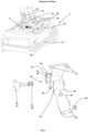
- FIG. 6 illustrates the adapter 30 in more detail.
- the adapter 30 comprises a longitudinal web 88 and two arch shaped elements 90.
- the arch shaped elements 90 are integrally connected to the web 88.
- FIG. 6 shows an exemplary embodiment of the adapter 30 it is however clear that other solutions and designs are possible.
- the holes and the arch shaped elements 90 may be arranged differently or the adapter 30 may comprise only one or several arch shaped elements 90.
- the adapter may comprise two longitudinal webs 88 instead of one.
- the arch shaped elements 90 are however beneficial since they provide a capability to absorb shocks or the like.
- Figure 7 illustrates a bigger perspective view of the battery unit 6 with the lower part of the handle unit 4 illustrated.
- the circuit board 20 mounted on the frame 18 is visible and also the adapter-frame fastening mechanism 50 that connects the frame 18 to the adapter 30.
- the cables 36 from the battery unit 6 are connected directly to the circuit board 20.
- the adapter 30 is fastened to the battery unit 6 via the adapter-battery unit fastening mechanism 82.
- the battery unit housing 70 comprises battery unit electronics 71, such as circuits and processors that are connected to the battery power ports and therewith the battery and the cables 3 that lead to the circuit board 20 of the handle unit 4. From figure 7 it becomes well visible how the interface handle unit 4 - battery unit 6 is designed and how the adapter 30 provides shock protection.
- the adapter 30 and the frame 18 in the figures are made of aluminum to provide good stability and a light weight. Other materials are possible as described herein. It is also possible to choose different materials for the frame 18 and the adapter 30.
- the screws and bolts used for the fastening mechanism can likewise be made of aluminum or steel.
- Figure 8 illustrates an explosion drawing of the frame 18 and the different components of the control button 26.
- the control button 26 comprises the trigger 62, the trigger adapter 64 that embeds and holds the trigger 62 via the splint 66 (c.f. figure 9 ) and a spring 68 that is embedded in the receiving cavity 44 for the control button in the frame 18.
- Figure 8 further illustrates the reverse button recess 46 and the frame- motor unit fastening mechanism 42.
- the frame-motor unit fastening mechanism 42 comprises a part at an upper end of the frame 18 that is built stronger and sturdier than the rest of the frame 18. Typically this part at the upper part of the frame 18 is about 20% to 70% thicker than the rest of the frame 18.
- a lower end of the frame 18, which lower end comprises of the adapter-frame fastening mechanism 50 is designed thicker and therewith sturdier than the rest of the frame 18 also with an increased thickness of about 20% to 70% thicker than the rest of the frame 18.
- the threaded holes for receiving bolts and/or screws are embedded in these parts of the upper end and the lower end of the frame 18.
- Figure 8 further illustrates the bolt opening 48 for receiving the bolt 60 and its sleeve 84.
- the bolt opening 48 is also designed and foreseen in the circuit board 20 and the insulation and protection element 21 so that this components can be attached to the frame 18 via the bolt 60 and the sleeve 84.
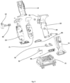
- Figure 9 illustrates an explosion illustration of the handle unit 4 and the battery unit 6 of the pistol tool without the pair of outer handle covers 16.
- Figure 9 however illustrates the inner handle covers 16, insulation and protection element 21, the frame 18, the circuit board 20, the battery housing 70, the trigger 62 of the control button 26 and a pair of antennas 86 used for communication with a factory network for example.
- the circuit board 20 may extend on both sides of the frame 18 as illustrated in figure 9 and it may also have a part that is embedded in the battery housing 70 when assembled. This part of the circuit board 20 that is embedded in the battery housing 70 when the pistol tool is assembled can for instance be positioned just below the adapter 30.
- Figure 9 further illustrates how the circuit board 20 and the insulation and protection element 21 extend around the receiving cavity 44 for the control button.
- the trigger 62 and the trigger adapter 64 including the spring 68 and the splint 66 that holds the trigger 62 in the trigger adapter 64 are also well visible in figure 9 . Pushing the trigger 62 will send a signal to the circuit board 20, for instance via a hall sensor, so that the circuit board 20 controls the motor unit 2 and the motor, respectively.
- the antennas 86 are configured to be attached to the battery housing 70 on either side of the adapter 30.
- the pair of antennas 86 can thereby be directly connected to circuit board 20 of the pistol tool 1 or via the cables 36.
- Figure 9 further illustrates the bolt 60 and the sleeve 84 for mounting the insulation and protection element 21, circuit board 30 and the inner handle covers 16 to the frame 18.
- the frame has been illustrated as a plate-like element it is however clear the it can have another design and structure such as a truss or framework design or it may contain multiple holes for optimizing weight.
Landscapes
- Engineering & Computer Science (AREA)
- Mechanical Engineering (AREA)
- Microelectronics & Electronic Packaging (AREA)
- Chemical & Material Sciences (AREA)
- Chemical Kinetics & Catalysis (AREA)
- Electrochemistry (AREA)
- General Chemical & Material Sciences (AREA)
- Battery Mounting, Suspending (AREA)
- Braking Systems And Boosters (AREA)
- Valve Device For Special Equipments (AREA)
- Cutting Tools, Boring Holders, And Turrets (AREA)
- Portable Nailing Machines And Staplers (AREA)
- Brushes (AREA)
- Forklifts And Lifting Vehicles (AREA)
Description
- In a first aspect the invention relates to the field of power tools such as for example pistol tools or other handheld tools for assembly lines and industrial applications. In a second aspect the invention also relates to the field of power tools in general even for hobby and building related applications.
- The manufacturing and application of power tools such as pistol tools has certain challenges especially in industrial environments such as for example assembly factories. Such factories typically have electromagnetic compatibility (EMC) and electrostatic discharge (ESD) standards that need to be followed and fulfilled. If they are not fulfilled problems with workers, for instance workers who have a pacemaker, or problems with sensitive equipment in general and sensitive assembly components can occur. In view of these EMC and ESD standards, power tools are today grounded via a cable if they are cable connected tools or they are grounded when connected to a controller that is close to the assembly area, which controller has ground level and therewith provides the same ground level to the tool. One issue that thereby occurs is that the tools or power tools do not have the same ground level across the entire tool due to the extensive use of plastic materials in the actual tool, which plastic electrically isolates several parts, such as for example the motor and the battery adapter, from one another leading to different ground levels in one and the same tool. Especially the handle part of the tool is widely made of plastic and therewith the motor unit and the battery adapter and the battery do not have the same ground level, which leads to problems with EMC and ESD standards since it is not entirely sure what kind of ground level the different parts of the tool have. One solution for this has been to introduce two metal plates into the shell of the handle on both inner sides of it, whereby the metal plates extend from the battery adapter to the motor unit. These metal plates are however cumbersome to install since they need to be bent at the edges and otherwise adapted and they are also difficult to assemble when the tool is produced and therewith make the tool expensive due the following:
Up to today the printed circuit boards (PCB), the controller, the buttons in particular the control button that controls the tool, the cables, the antennas and other components are pressed into one of two handle-shells and then the other handle shell is just pressed onto the first handle shell and screwed tight. The handle shells are typically left and right handle shells. One can imagine that this leads to quite some challenges and uncertainty as to where the actual components are placed once the handle is closed. These challenges are further increased when each handle shell needs to house a metal plate for providing the same ground level across the entire tool. In addition, it is cumbersome and expensive to provide metal plates that fit into the handle shells and do not destroy any other components such as cables or antennas. The assembly of the components within one shell of the handle makes it also very difficult to repair the power tool and replace components. Usually, the entire handle has to be disassembled, the component replaced and then the handle reassembled, which takes time and therewith leads to long down times of such power tools or pistol tools. - Another shortcoming with prior art power tools is that the connection or interface between handle and battery adapter and battery, respectively is rather rigid and stiff. When the power tool thus gets an impact, for example due to falling to the ground, it tends to break at the interface or intersection battery adapter and battery, respectively, and handle.
-
US2015/340921 , disclosing the preamble ofclaim 1,US2015/314434 ,WO2019/211048 ,CN110337735 andUS9931118 - An object of the present invention is therefore to provide an improved power tool.
- Another object of the present invention is to provide a power tool such as a pistol tool that is reliable, robust and easy to assemble.
- The inventor of the present invention has discovered that the above-described challenges and problems with prior art power tools such as pistol tools can be overcome by providing a power tool having a battery unit, a handle unit and a motor unit, whereby the handle unit comprises a frame that interconnects the battery unit with the motor unit. The frame is thereby made of an electrically conductive material that is strong and robust, such as for example aluminum or conductive fibre, such as metal fibre, reinforced plastic. The advantage of such as solution is that the PCBs, the controller, the cables, the antenna, the communication unit and other components can be assembled to the frame and not into a handle shell. This leads to a cleanly assembled power tool that has the same ground level over the entire tool. By providing an adapter between the frame and the battery unit, which adapter is capable of absorbing shocks and impacts, whereby the adapter is also made of an electrically conductive material such as aluminum, steel or metal fibre, reinforced plastic, it is further possible to make the power tool resistant to destruction at the handle - battery unit interface. The inventor has further realized that this resistance to destruction can further be increased when inner handle covers and outer handle covers with different amounts of glass fibres embedded in plastic are provided, whereby the inner handle covers are made less stiff than the outer handle covers.
- Disclosed herein is a power tool for example a pistol tool or any other hand held power tool comprising a motor unit comprising a motor and a drive axle connected to the motor, a battery unit configured to receive a battery and a handle unit interconnecting the motor unit and the battery unit, the handle unit comprising:
- a frame extending from the motor unit to the battery unit;
- a control button mounted to the frame for controlling the pistol tool;
- a circuit board mounted to the frame and connected to the control button;
- cables interconnecting the battery unit, the printed circuit board and the motor unit;
- an antenna connected to the printed circuit board for communication of the pistol tool with external devices;
- a pair of outer handle covers for covering the handle unit;
- In such an embodiment the frame provides a basis for the mounting of all other components in the handle and at the same time the frame provides one and the same ground level across the entire tool from the motor unit to the battery unit and the battery when the battery is coupled. Thus the frame serves as mounting platform for the other components in the handle unit.
- Since the frame provides the basis for mounting the components one of the outer handle cover can be removed and all the components stay cleanly and neatly in place, which facilitates maintenance and repair of the pistol tool.
- In an embodiment the frame may be made of a metal such as aluminium, steel or titan or of an electrically conductive fibre reinforced plastic.
- All of these materials are electrically conductive and therefore they enable the grounding of the entire power tool.
- According to the invention, the handle unit comprises an adapter that is connected to the frame and the battery unit, whereby the adapter is electrically conductive and designed to have shock absorbing capabilities.
- The adapter may be integrally formed with the frame or the battery unit or both. The adapter helps to reduce the risk of a pistol tool breaking at the interface handle unit - battery unit in case of a fall for instance.
- In an embodiment the adapter may also be made of a metal such as aluminium, steel or titan or electrically conductive fibre reinforced plastic.
- This helps that the conductivity is established from motor unit to the battery unit.
- In another embodiment the adapter may comprise a longitudinal web and at least one arch-shaped element connected to the longitudinal web and the adapter may comprise an electrically conductive adapter - battery unit fastening mechanism and an electrically conductive adapter - frame fastening mechanism.
- The above design of the adapter helps to improve the shock absorbing properties of the adapter and ensures a good and reliable connection to the handle unit and the battery unit, respectively.
- The adapter may comprise two arch-shaped elements and one web or two webs and two arch-shaped elements for improved stability and reliability.
- In an embodiment the frame may comprise a frame - motor unit fastening mechanism and a frame - adapter fastening mechanism, wherein the frame - motor unit fastening mechanism and the frame - adapter fastening mechanism are electrically conductive, said mechanisms being used for connecting the frame to the motor unit and the adapter and therewith the battery unit.
- These fastening mechanisms provide a reliable and strong connection between handle unit and motor unit and handle unit and battery unit and adapter, respectively. At the same time the fastening mechanisms are electrically conductive for providing one and the same ground level across the entire pistol tool.
- In an embodiment the handle unit further may further comprise a pair of inner handle covers configured to be arranged around the frame and printed circuit board and configured to be arranged on an inner side of the pair of outer handle covers.
- The pair of inner handle covers are made of glass fibre reinforced plastic comprising 20% to 30% by weight glass fibres and wherein the pair of outer handle covers are made of glass fibre reinforced plastic comprising 25% to 35% by weight glass fibres.
- The pair of inner handle covers may further improve the shock resistance of the pistol tool. In particular if the amount of glass fibres is chosen to be less in percentage by weight as in the pair of outer handle covers, then the distribution of the shock or load is improved in case of an impact, since the pair of inner handle covers are allowed to be deformed with less force or shock than the pair of outer handle covers which leads to an optimized load distribution and therewith a higher shock resistance.
- In an embodiment the frame may further comprise a bolt opening configured to receive a bolt for fastening the printed circuit board and the pair of inner handle covers, the bolt being made of electrically conductive material and configured to physically touch the printed circuit board.
- The bold may be advantageous for a clean and robust assembly at the same time it may provide grounding to the printed circuit board. This grounding may alternatively be provided via an electrically conductive sleeve that is arranged around the bolt.
- In an embodiment at least one of the pair of inner handle covers comprises a channel for receiving and embedding cables.
- This will lead to a better and safer arrangement of the cables and therewith to a more durable pistol tool.
- In an embodiment the frame may comprise a receiving cavity for mounting the control button.
- Such a receiving cavity facilitates the replacement of the control button in case it breaks. The control button and its trigger, respectively, may be fastened via a splint or the like in a trigger adapter, which is embedded via a spring in the receiving cavity. Removing the splint will allow to easily replace the control button. Other solutions may of course be used but the receiving cavity also facilitates assembly of the control button.
- In an embodiment the handle unit may further comprise an insulation and protection element that is connected to the frame in between the frame and the printed circuit board.
- This insulation and protection element may be made of an electrically insulating and rather soft material so that it can protect the printed circuit board and other sensitive electric components from electric discharges or shocks or the like.
- In an embodiment the outer handle cover may extend from the motor unit to the battery unit.
- This provides for a stable covering of the handle unit.
- Herein the term "electrically conductive and strong material" generally means either some type of metal such as aluminium, steel, titan or an alloy thereof or fibre reinforced plastic, whereby the fibres may be electrically conductive carbon fibres or metal fibres.
- Herein the term "fastening mechanism" refers generally to thread, bolt, hole and screw combinations for fastening components to one another. Other fastening mechanisms such as form fit or force fit connections and even adhesive induced connections or electrically conductive adhesive induced connections are covered by this term.
- The present invention will now be described, for exemplary purposes, in more detail by way of an embodiment(s) and with reference to the enclosed drawings, in which:
- Fig. 1
- schematically illustrates in a perspective view a power tool according to the invention;
- Fig. 2
- schematically illustrates in a perspective view the pistol tool of
figure 1 with certain parts removed for better illustration of features; - Fig. 3
- schematically illustrates in a perspective view the pistol tool according to
figure 2 with even more parts removed for still better illustration of features; - Fig. 4
- schematically illustrates in a perspective view a pair of inner handle covers of the pistol tool;
- Fig. 5
- schematically illustrates in a perspective view the pistol tool according to
figure 3 with removed inner handle covers; - Fig. 6
- schematically illustrates in a perspective view an adapter for connection of a handle unit to a battery unit;
- Fig. 7
- schematically illustrates in a perspective view the connection handle unit - battery unit;
- Fig. 8
- schematically illustrates in a perspective view a frame with a control button; and
- Fig. 9
- schematically illustrates in an explosion illustration the handle unit and the battery unit.
-
Figure 1 illustrates apistol tool 1 having amotor unit 2, handleunit 4 and abattery unit 6. Thepistol tool 1 is shown without a battery, it is however clear that a battery can be coupled to thebattery unit 6. Themotor unit 2 comprises amotor housing 12 and a motor 10 (c.f.figure 2 ). Themotor 10 is driving a drive axle 38 (c.f.figure 2 ) having abit connector 40. Thehandle unit 4 comprises areverse button 28 to change the rotational direction of the motor and therewith the axle 38 and thebit connector 40, respectively. Then handleunit 4 further comprises acontrol button 26 with atrigger 62 and a pair of outer handle covers 14 arranged to cover thehandle unit 4. The pair of outer handle covers 14 extend from themotor unit 2 to thebattery unit 6 and are fastened to themotor unit 2 and thebattery unit 6 via an outer handlecover fastening mechanism 72, as shown infigure 2 . The outer handlecover fastening mechanism 72 comprises of a thread-hole, screw bolt and hole combination as illustrated infigures 1 and 2 . - Turning now to
figure 2 , which shows thesame pistol tool 1 asfigure 1 but with removed front cap and bit adapter and also with a removed, left,outer handle cover 14. The pair of outer handle covers 14 each comprise areverse button recess 46 that extends through the outer handle covers 14. Thereverse button recess 46 is also formed in aframe 18 of thehandle unit 4, whichframe 18 holds a printed circuit board (figure 6 ) and other components as further explained herein. Theframe 18 illustrated infigure 2 extends from themotor unit 2 down to thebattery unit 6 and is made of an electrically conductive material to provide the same ground level across theentire pistol tool 1. Illustrated is also thecontrol button 26 with itstrigger 62 that sits in atrigger adapter 64.Figure 2 further illustrates a pair of inner handle covers 16 of thehandle unit 4, at least one of the inner handle covers 16 of said pair of inner handle covers 16 comprising acable channel 74 comprisingcables 24 interconnecting themotor unit 2 with thehandle unit 4 and its printed circuit board (c.f.figure 6 ) and thebattery unit 6. Thecables 24 further connect theantennas 54, arranged on both sides of thehandle unit 4 with the printed circuit board and controller (not shown infigure 2 ). Thebattery unit 6 comprisesbattery receivers 34 for receiving a battery in a form-fit manner, for instance a slide and lock mechanism. As mentioned in the introductory part, the pair of outer handle covers 14 are made of 25% to 35% glass fibres, preferably 30%, glass fibres embedded in plastic whereby the percentage relates to weight-percentages and the pair of inner handle covers 16 are made of 20% to 30%, preferably 25%, glass fibre embedded plastic. This differing amount of glass fibre leads to an optimal distribution of load in case of shocks and impacts and/or deformations in thepistol tool 1. - Turning now to
figure 3 , which illustrates, in more detail, some additional features of thepistol tool 1 according to the invention. Theframe 18 comprises a frame motorunit fastening mechanism 42 and a receivingcavity 44 for receiving thecontrol button 26 with itstrigger 62 andtrigger adapter 64. The frame motorunit fastening mechanism 42 comprises of an electrically conductive bolt, thread hole and hole combination. Thetrigger 62 is locked in thetrigger adapter 64 via asplint 66, which splint also makes it easier to replace thetrigger 62 in case it is damaged. In the receiving cavity 44 a spring (not visible infigure 3 , c.f.figure 9 ) is embedded that pushes thecontrol button 26 away from the receivingcavity 44. Theframe 18 has an upper part that is wider than the width at the actual handle of thehandle unit 4. Theframe 18 is further made of aluminum and is basically a spline or metal spline. -
Figure 3 further illustrates theinner handle cover 16, whereby at least the leftinner handle cover 14 comprises acable channel 74 for, illustrated without cables inside infigure 3 , for receiving the cables hold them tidy in place during assembly and afterwards. The pair of inner handle covers 16 are fastened to thebattery unit 6 via an inner handlecover fastening mechanism 76, which again comprises a thread hole, bolt and hole combination. The thread holes of the outer handlecover fastening mechanism 72 is also visible infigure 3 as well as abolt 60 for fastening the pair of inner handle covers 16 to theframe 18. Thisbolt 60 also helps to keep the printed circuit board in position and connected to theframe 18. -
Figure 4 illustrates the pair of inner handle covers 16 comprising afoot part 78 where the inner handlecover fastening mechanism 76 is located. -
Figures 5 illustrates theframe 18 of thehandle unit 4 clearer since the pair of inner handle covers 16 are not shown. Mounted on theframe 18 is the printedcircuit board 20 orcircuit board 20 comprisingvarious circuit 52 and acommunication unit 56. Thecircuit board 20 also comprises a computer processing unit (CPU) 55, it is mounted to theframe 18 via thebolt 60 and it is connected to thebattery unit 6 viacables 36. Thebolt 60 is also providing a grounding function since it electrically connects theframe 18 with thecircuit board 20 via asleeve 84, as shown infigure 9 . In between thecircuit board 20 and theframe 18 an insulation and protection element 21 (c.f.figure 9 ) is arranged. The protection andinsulation element 21 is made of rubber or another suitable material that electrically insulates thecircuit board 20 from theframe 18 and the insulation andprotection element 21 also works as cushion to protect thecircuit board 20 from shocks and other physical impacts. Theframe 18 is connected to thebattery unit 6 via anadapter 30, which is also illustrated infigure 6 . Theadapter 30 is made of an electrically conductive material, such as metal like aluminum, titan or steel or plastic reinforced with electrically conductive fibers. Theadapter 30 is designed as a shock absorbing element that can absorb shocks when thepistol tool 1 falls down or gets another impact via thebattery unit 6 when the battery is connected. Theframe 18 is connected to theadapter 30 via an adapter-frame fastening mechanism 50 and theadapter 30 is connected to thebattery unit 6 via an adapter-batteryunit fastening mechanism 82. - The
adapter 30 is connected to thebattery unit 6 via abattery unit housing 70. -
Figure 6 illustrates theadapter 30 in more detail. Theadapter 30 comprises a longitudinal web 88 and two arch shapedelements 90. The arch shapedelements 90 are integrally connected to the web 88. On the sides where the arch shapedelements 90 are not connected to the web 88 they comprisefeet 91 that ease the mounting of theadapter 30 and increase stability when theadapter 30 is mounted. On the highest point of the arch shapedelements 90 the holes of the adapter-frame fastening mechanism 50 are shown, said holes being designed for receiving a screw or bolt of the adapter-frame fastening mechanism 50. On one end of the web 88 a hole of the adapter-batteryunit fastening mechanism 82 is shown, said hole being for receiving a screw or bolt of the adapter-batteryunit fastening mechanism 82. The other hole of the adapter-batteryunit fastening mechanism 82 is shown on one of thefeet 91 of the arch shapedelement 90.Figure 6 shows an exemplary embodiment of theadapter 30 it is however clear that other solutions and designs are possible. The holes and the arch shapedelements 90 may be arranged differently or theadapter 30 may comprise only one or several arch shapedelements 90. In addition, the adapter may comprise two longitudinal webs 88 instead of one. The arch shapedelements 90 are however beneficial since they provide a capability to absorb shocks or the like. -
Figure 7 illustrates a bigger perspective view of thebattery unit 6 with the lower part of thehandle unit 4 illustrated. - The
circuit board 20 mounted on theframe 18 is visible and also the adapter-frame fastening mechanism 50 that connects theframe 18 to theadapter 30. Thecables 36 from thebattery unit 6 are connected directly to thecircuit board 20. Theadapter 30 is fastened to thebattery unit 6 via the adapter-batteryunit fastening mechanism 82. Thebattery unit housing 70 comprisesbattery unit electronics 71, such as circuits and processors that are connected to the battery power ports and therewith the battery and the cables 3 that lead to thecircuit board 20 of thehandle unit 4. Fromfigure 7 it becomes well visible how the interface handle unit 4 -battery unit 6 is designed and how theadapter 30 provides shock protection. Theadapter 30 and theframe 18 in the figures are made of aluminum to provide good stability and a light weight. Other materials are possible as described herein. It is also possible to choose different materials for theframe 18 and theadapter 30. The screws and bolts used for the fastening mechanism can likewise be made of aluminum or steel. -
Figure 8 illustrates an explosion drawing of theframe 18 and the different components of thecontrol button 26. Thecontrol button 26 comprises thetrigger 62, thetrigger adapter 64 that embeds and holds thetrigger 62 via the splint 66 (c.f.figure 9 ) and aspring 68 that is embedded in the receivingcavity 44 for the control button in theframe 18.Figure 8 further illustrates thereverse button recess 46 and the frame- motorunit fastening mechanism 42. The frame-motorunit fastening mechanism 42 comprises a part at an upper end of theframe 18 that is built stronger and sturdier than the rest of theframe 18. Typically this part at the upper part of theframe 18 is about 20% to 70% thicker than the rest of theframe 18. In a similar manner, a lower end of theframe 18, which lower end comprises of the adapter-frame fastening mechanism 50 is designed thicker and therewith sturdier than the rest of theframe 18 also with an increased thickness of about 20% to 70% thicker than the rest of theframe 18. The threaded holes for receiving bolts and/or screws are embedded in these parts of the upper end and the lower end of theframe 18.Figure 8 further illustrates thebolt opening 48 for receiving thebolt 60 and itssleeve 84. Thebolt opening 48 is also designed and foreseen in thecircuit board 20 and the insulation andprotection element 21 so that this components can be attached to theframe 18 via thebolt 60 and thesleeve 84. -
Figure 9 illustrates an explosion illustration of thehandle unit 4 and thebattery unit 6 of the pistol tool without the pair of outer handle covers 16.Figure 9 however illustrates the inner handle covers 16, insulation andprotection element 21, theframe 18, thecircuit board 20, thebattery housing 70, thetrigger 62 of thecontrol button 26 and a pair ofantennas 86 used for communication with a factory network for example. Thecircuit board 20 may extend on both sides of theframe 18 as illustrated infigure 9 and it may also have a part that is embedded in thebattery housing 70 when assembled. This part of thecircuit board 20 that is embedded in thebattery housing 70 when the pistol tool is assembled can for instance be positioned just below theadapter 30.Figure 9 further illustrates how thecircuit board 20 and the insulation andprotection element 21 extend around the receivingcavity 44 for the control button. Thetrigger 62 and thetrigger adapter 64 including thespring 68 and thesplint 66 that holds thetrigger 62 in thetrigger adapter 64 are also well visible infigure 9 . Pushing thetrigger 62 will send a signal to thecircuit board 20, for instance via a hall sensor, so that thecircuit board 20 controls themotor unit 2 and the motor, respectively. - The
antennas 86 are configured to be attached to thebattery housing 70 on either side of theadapter 30. The pair ofantennas 86 can thereby be directly connected tocircuit board 20 of thepistol tool 1 or via thecables 36.Figure 9 further illustrates thebolt 60 and thesleeve 84 for mounting the insulation andprotection element 21,circuit board 30 and the inner handle covers 16 to theframe 18. - The frame has been illustrated as a plate-like element it is however clear the it can have another design and structure such as a truss or framework design or it may contain multiple holes for optimizing weight.
- The invention has now been described and disclosed and its advantages have been explained according to an embodiment illustrated in the figures.
Claims (12)
- A power tool comprising a motor unit (2) comprising a motor (10) and a drive axle (38) connected to the motor (10), a battery unit (6) configured to receive a battery and a handle unit (4) interconnecting the motor unit (2) and the battery unit (6), the handle unit (4) comprising:- a frame (18) extending from the motor unit (2) to the battery unit (6);- a control button (26) mounted to the frame (18) for controlling the power tool;- a circuit board (20) mounted to the frame (18) and connected to the control button (26);- cables (24, 36) interconnecting the battery unit (6), the circuit board (20) and the motor unit (2);- an antenna (86) connected to the circuit board (20) for communication of the power tool with external devices;- a pair of outer handle covers (14) for covering the handle unit (4);characterized in that the frame (18) is made of an electrically conductive material, and wherein the handle unit (4) further comprises an adapter (30) that is connected to the frame (18) and the battery unit (4), whereby the adapter (30) is electrically conductive and designed to have shock absorbing capabilities.
- The power tool according to claim 1, wherein the frame (18) is made of a metal such as aluminium, steel or titanium or of electrically conductive fibre reinforced plastic.
- The power tool according to claim 2, wherein the adapter (30) is made of a metal such as aluminium, steel or titanium or electrically conductive fibre reinforced plastic.
- The power tool according to any of claims 2 or 3, wherein the adapter (30) comprises a longitudinal web (88) and at least one arch-shaped element (90) connected to the longitudinal web (88) and wherein the adapter (30) comprises an electrically conductive adapter - battery unit fastening mechanism (82) and an electrically conductive adapter - frame fastening mechanism (50).
- The power tool according to any of the preceding claims 2 to 4, wherein the frame (18) comprises a frame - motor unit fastening mechanism (42) and a frame - adapter fastening mechanism (50), wherein the frame - motor unit fastening mechanism (42) and the frame - adapter fastening mechanism (50) are electrically conductive, said mechanisms being used for connecting the frame (18) to the motor unit (2) and the adapter (30) and therewith the battery unit (6).
- The power tool according to any of claims 1 to 5, wherein the handle unit (4) further comprises a pair of inner handle covers (16) configured to be arranged around the frame (18) and circuit board (20) and configured to be arranged on an inner side of the pair of outer handle covers (14).
- The power tool according to claim 6, wherein the pair of inner handle covers (16) are made of glass fibre reinforced plastic comprising 20% to 30% by weight glass fibres and wherein the pair of outer handle covers (14) are made of glass fibre reinforced plastic comprising 25% to 35% by weight glass fibres.
- The power tool according to any of the preceding claims 6 or 7, wherein the frame (18) further comprises a bolt and a bolt opening (48) configured to receive said bolt (60) for fastening the circuit board (20) and the pair of inner handle covers (16), the bolt (60) being made of electrically conductive material and configured to physically touch the circuit board (20).
- The power tool according to any of claims 6 to 8, wherein at least one of the pair of inner handle covers (16) comprises a channel (74) for receiving and embedding cables (24).
- The power tool according to any of the preceding claims, wherein the frame (18) comprises a receiving cavity (44) for mounting the control button (26).
- The power tool according to any of the preceding claims, wherein the handle unit (4) further comprise an insulation and protection element (21) that is connected to the frame (18) in between the frame and the circuit board (20).
- The power tool according to any of the preceding claims, wherein the outer handle cover (14) extends from the motor unit (2) to the battery unit (4).
Applications Claiming Priority (2)
| Application Number | Priority Date | Filing Date | Title |
|---|---|---|---|
| SE2130126A SE545235C2 (en) | 2021-05-10 | 2021-05-10 | Power tool with a frame made from an electrically conductive material |
| PCT/EP2022/059453 WO2022238061A1 (en) | 2021-05-10 | 2022-04-08 | Power tool |
Publications (2)
| Publication Number | Publication Date |
|---|---|
| EP4337424A1 EP4337424A1 (en) | 2024-03-20 |
| EP4337424B1 true EP4337424B1 (en) | 2025-03-12 |
Family
ID=81595668
Family Applications (1)
| Application Number | Title | Priority Date | Filing Date |
|---|---|---|---|
| EP22722162.9A Active EP4337424B1 (en) | 2021-05-10 | 2022-04-08 | Power tool |
Country Status (7)
| Country | Link |
|---|---|
| US (1) | US12030169B1 (en) |
| EP (1) | EP4337424B1 (en) |
| KR (1) | KR102721291B1 (en) |
| CN (1) | CN117295588B (en) |
| PL (1) | PL4337424T3 (en) |
| SE (1) | SE545235C2 (en) |
| WO (1) | WO2022238061A1 (en) |
Families Citing this family (1)
| Publication number | Priority date | Publication date | Assignee | Title |
|---|---|---|---|---|
| JP1759566S (en) * | 2022-11-03 | 2023-12-14 | portable electric screwdriver |
Citations (1)
| Publication number | Priority date | Publication date | Assignee | Title |
|---|---|---|---|---|
| US9931118B2 (en) * | 2015-02-27 | 2018-04-03 | Ethicon Endo-Surgery, Llc | Reinforced battery for a surgical instrument |
Family Cites Families (11)
| Publication number | Priority date | Publication date | Assignee | Title |
|---|---|---|---|---|
| US20080196910A1 (en) * | 2000-06-20 | 2008-08-21 | Radle Patrick J | Electrical sensing device modules for attachment to power tools and drills |
| JP5936302B2 (en) * | 2010-12-28 | 2016-06-22 | 日立工機株式会社 | Electric tool |
| US9281770B2 (en) * | 2012-01-27 | 2016-03-08 | Ingersoll-Rand Company | Precision-fastening handheld cordless power tools |
| US9393683B2 (en) * | 2014-05-02 | 2016-07-19 | M. W. Bevins Co. | Conductive boot for power tool protection |
| JP2015223637A (en) * | 2014-05-26 | 2015-12-14 | 株式会社マキタ | Electric power tool |
| WO2018150672A1 (en) | 2017-02-15 | 2018-08-23 | 株式会社村田製作所 | Battery pack, electronic device, vehicle, electric tool and electrical energy storage system |
| CA3067183A1 (en) * | 2017-06-16 | 2018-12-20 | Koki Holdings Co., Ltd. | Battery pack capable of switching a connection state of a plurality of cell units and electric apparatus using battery pack |
| EP3664970B1 (en) * | 2017-08-07 | 2026-04-29 | Milwaukee Electric Tool Corporation | Power tool with irreversably lockable compartment |
| DE102018206876A1 (en) | 2018-05-04 | 2019-11-07 | Robert Bosch Gmbh | Machine tool device |
| US11571803B2 (en) * | 2019-05-30 | 2023-02-07 | Milwaukee Electric Tool Corporation | Power tool with combined chip for wireless communications and power tool control |
| CN112238411B (en) * | 2019-07-19 | 2024-02-20 | 株式会社牧田 | Electric tool and rotary tool |
-
2021
- 2021-05-10 SE SE2130126A patent/SE545235C2/en unknown
-
2022
- 2022-04-08 PL PL22722162.9T patent/PL4337424T3/en unknown
- 2022-04-08 CN CN202280034025.6A patent/CN117295588B/en active Active
- 2022-04-08 EP EP22722162.9A patent/EP4337424B1/en active Active
- 2022-04-08 US US18/558,036 patent/US12030169B1/en active Active
- 2022-04-08 WO PCT/EP2022/059453 patent/WO2022238061A1/en not_active Ceased
- 2022-04-08 KR KR1020237037322A patent/KR102721291B1/en active Active
Patent Citations (1)
| Publication number | Priority date | Publication date | Assignee | Title |
|---|---|---|---|---|
| US9931118B2 (en) * | 2015-02-27 | 2018-04-03 | Ethicon Endo-Surgery, Llc | Reinforced battery for a surgical instrument |
Also Published As
| Publication number | Publication date |
|---|---|
| KR102721291B1 (en) | 2024-10-24 |
| US12030169B1 (en) | 2024-07-09 |
| CN117295588A (en) | 2023-12-26 |
| CN117295588B (en) | 2025-01-28 |
| US20240208030A1 (en) | 2024-06-27 |
| PL4337424T3 (en) | 2025-07-07 |
| SE2130126A1 (en) | 2022-11-11 |
| SE545235C2 (en) | 2023-05-30 |
| EP4337424A1 (en) | 2024-03-20 |
| WO2022238061A1 (en) | 2022-11-17 |
| KR20230162095A (en) | 2023-11-28 |
Similar Documents
| Publication | Publication Date | Title |
|---|---|---|
| EP4337424B1 (en) | Power tool | |
| US9033379B2 (en) | Door handle device for vehicle | |
| CN103362057A (en) | External control stand for construction machine | |
| AU2010331849B2 (en) | Plug-in module for controllers of mobile working machines | |
| CN118783152A (en) | Module connector | |
| EP1450135B1 (en) | Inductive sensor and rotary encoder using the same | |
| US20100091470A1 (en) | Power tool with electronic control unit | |
| CN211267263U (en) | Rigid-flex circuit board | |
| GB2473716A (en) | Switch-circuit board unit with circuit board rigidly mounted to switch | |
| EP3437444B1 (en) | Arrangement arranged to enclose a circuit board comprising electronic components and a tool comprising the arrangement | |
| CN211046357U (en) | Electrical engineering cable protection device | |
| CN218632807U (en) | Protection seat, distribution box and power supply product | |
| JP4906088B2 (en) | Mounting structure for live cover | |
| JP4730950B2 (en) | Circuit breaker terminal structure | |
| CN222073487U (en) | Fracture-preventing multilayer composite circuit board | |
| CN218866963U (en) | Safety protection type knife switch | |
| CN218939565U (en) | Fixing device of binding screw and moulded case circuit breaker | |
| KR890005039Y1 (en) | Printed Circuit Board Protection Case | |
| EP4624103A1 (en) | Hand-held power tool | |
| KR20130104699A (en) | Weft sensing device for air jet loom | |
| KR102071973B1 (en) | Busbar assembly | |
| CN103596731A (en) | Machine tool device | |
| CN102047506A (en) | Locking cap for a connector-fastening screw | |
| HK40007567A (en) | Handle support module | |
| KR200480762Y1 (en) | The Reinforcement Structure for Power Supply Adaptor Case |
Legal Events
| Date | Code | Title | Description |
|---|---|---|---|
| STAA | Information on the status of an ep patent application or granted ep patent |
Free format text: STATUS: UNKNOWN |
|
| STAA | Information on the status of an ep patent application or granted ep patent |
Free format text: STATUS: THE INTERNATIONAL PUBLICATION HAS BEEN MADE |
|
| PUAI | Public reference made under article 153(3) epc to a published international application that has entered the european phase |
Free format text: ORIGINAL CODE: 0009012 |
|
| STAA | Information on the status of an ep patent application or granted ep patent |
Free format text: STATUS: REQUEST FOR EXAMINATION WAS MADE |
|
| 17P | Request for examination filed |
Effective date: 20231211 |
|
| AK | Designated contracting states |
Kind code of ref document: A1 Designated state(s): AL AT BE BG CH CY CZ DE DK EE ES FI FR GB GR HR HU IE IS IT LI LT LU LV MC MK MT NL NO PL PT RO RS SE SI SK SM TR |
|
| DAV | Request for validation of the european patent (deleted) | ||
| DAX | Request for extension of the european patent (deleted) | ||
| GRAP | Despatch of communication of intention to grant a patent |
Free format text: ORIGINAL CODE: EPIDOSNIGR1 |
|
| STAA | Information on the status of an ep patent application or granted ep patent |
Free format text: STATUS: GRANT OF PATENT IS INTENDED |
|
| INTG | Intention to grant announced |
Effective date: 20241018 |
|
| GRAS | Grant fee paid |
Free format text: ORIGINAL CODE: EPIDOSNIGR3 |
|
| GRAA | (expected) grant |
Free format text: ORIGINAL CODE: 0009210 |
|
| STAA | Information on the status of an ep patent application or granted ep patent |
Free format text: STATUS: THE PATENT HAS BEEN GRANTED |
|
| AK | Designated contracting states |
Kind code of ref document: B1 Designated state(s): AL AT BE BG CH CY CZ DE DK EE ES FI FR GB GR HR HU IE IS IT LI LT LU LV MC MK MT NL NO PL PT RO RS SE SI SK SM TR |
|
| REG | Reference to a national code |
Ref country code: GB Ref legal event code: FG4D |
|
| REG | Reference to a national code |
Ref country code: CH Ref legal event code: EP |
|
| REG | Reference to a national code |
Ref country code: DE Ref legal event code: R096 Ref document number: 602022011740 Country of ref document: DE |
|
| REG | Reference to a national code |
Ref country code: IE Ref legal event code: FG4D |
|
| P01 | Opt-out of the competence of the unified patent court (upc) registered |
Free format text: CASE NUMBER: APP_12095/2025 Effective date: 20250312 |
|
| PG25 | Lapsed in a contracting state [announced via postgrant information from national office to epo] |
Ref country code: RS Free format text: LAPSE BECAUSE OF FAILURE TO SUBMIT A TRANSLATION OF THE DESCRIPTION OR TO PAY THE FEE WITHIN THE PRESCRIBED TIME-LIMIT Effective date: 20250612 |
|
| PG25 | Lapsed in a contracting state [announced via postgrant information from national office to epo] |
Ref country code: FI Free format text: LAPSE BECAUSE OF FAILURE TO SUBMIT A TRANSLATION OF THE DESCRIPTION OR TO PAY THE FEE WITHIN THE PRESCRIBED TIME-LIMIT Effective date: 20250312 |
|
| PGFP | Annual fee paid to national office [announced via postgrant information from national office to epo] |
Ref country code: DE Payment date: 20250529 Year of fee payment: 4 |
|
| PG25 | Lapsed in a contracting state [announced via postgrant information from national office to epo] |
Ref country code: ES Free format text: LAPSE BECAUSE OF FAILURE TO SUBMIT A TRANSLATION OF THE DESCRIPTION OR TO PAY THE FEE WITHIN THE PRESCRIBED TIME-LIMIT Effective date: 20250312 |
|
| REG | Reference to a national code |
Ref country code: LT Ref legal event code: MG9D |
|
| PG25 | Lapsed in a contracting state [announced via postgrant information from national office to epo] |
Ref country code: NO Free format text: LAPSE BECAUSE OF FAILURE TO SUBMIT A TRANSLATION OF THE DESCRIPTION OR TO PAY THE FEE WITHIN THE PRESCRIBED TIME-LIMIT Effective date: 20250612 |
|
| PG25 | Lapsed in a contracting state [announced via postgrant information from national office to epo] |
Ref country code: HR Free format text: LAPSE BECAUSE OF FAILURE TO SUBMIT A TRANSLATION OF THE DESCRIPTION OR TO PAY THE FEE WITHIN THE PRESCRIBED TIME-LIMIT Effective date: 20250312 |
|
| REG | Reference to a national code |
Ref country code: NL Ref legal event code: MP Effective date: 20250312 |
|
| PG25 | Lapsed in a contracting state [announced via postgrant information from national office to epo] |
Ref country code: LV Free format text: LAPSE BECAUSE OF FAILURE TO SUBMIT A TRANSLATION OF THE DESCRIPTION OR TO PAY THE FEE WITHIN THE PRESCRIBED TIME-LIMIT Effective date: 20250312 |
|
| PG25 | Lapsed in a contracting state [announced via postgrant information from national office to epo] |
Ref country code: BG Free format text: LAPSE BECAUSE OF FAILURE TO SUBMIT A TRANSLATION OF THE DESCRIPTION OR TO PAY THE FEE WITHIN THE PRESCRIBED TIME-LIMIT Effective date: 20250312 Ref country code: GR Free format text: LAPSE BECAUSE OF FAILURE TO SUBMIT A TRANSLATION OF THE DESCRIPTION OR TO PAY THE FEE WITHIN THE PRESCRIBED TIME-LIMIT Effective date: 20250613 |
|
| REG | Reference to a national code |
Ref country code: AT Ref legal event code: MK05 Ref document number: 1774624 Country of ref document: AT Kind code of ref document: T Effective date: 20250312 |
|
| PG25 | Lapsed in a contracting state [announced via postgrant information from national office to epo] |
Ref country code: NL Free format text: LAPSE BECAUSE OF FAILURE TO SUBMIT A TRANSLATION OF THE DESCRIPTION OR TO PAY THE FEE WITHIN THE PRESCRIBED TIME-LIMIT Effective date: 20250312 |
|
| PG25 | Lapsed in a contracting state [announced via postgrant information from national office to epo] |
Ref country code: SE Free format text: LAPSE BECAUSE OF FAILURE TO SUBMIT A TRANSLATION OF THE DESCRIPTION OR TO PAY THE FEE WITHIN THE PRESCRIBED TIME-LIMIT Effective date: 20250312 |
|
| PG25 | Lapsed in a contracting state [announced via postgrant information from national office to epo] |
Ref country code: SM Free format text: LAPSE BECAUSE OF FAILURE TO SUBMIT A TRANSLATION OF THE DESCRIPTION OR TO PAY THE FEE WITHIN THE PRESCRIBED TIME-LIMIT Effective date: 20250312 |
|
| PG25 | Lapsed in a contracting state [announced via postgrant information from national office to epo] |
Ref country code: PT Free format text: LAPSE BECAUSE OF FAILURE TO SUBMIT A TRANSLATION OF THE DESCRIPTION OR TO PAY THE FEE WITHIN THE PRESCRIBED TIME-LIMIT Effective date: 20250714 |
|
| PG25 | Lapsed in a contracting state [announced via postgrant information from national office to epo] |
Ref country code: IT Free format text: LAPSE BECAUSE OF FAILURE TO SUBMIT A TRANSLATION OF THE DESCRIPTION OR TO PAY THE FEE WITHIN THE PRESCRIBED TIME-LIMIT Effective date: 20250312 |
|
| PG25 | Lapsed in a contracting state [announced via postgrant information from national office to epo] |
Ref country code: AT Free format text: LAPSE BECAUSE OF FAILURE TO SUBMIT A TRANSLATION OF THE DESCRIPTION OR TO PAY THE FEE WITHIN THE PRESCRIBED TIME-LIMIT Effective date: 20250312 |
|
| PG25 | Lapsed in a contracting state [announced via postgrant information from national office to epo] |
Ref country code: EE Free format text: LAPSE BECAUSE OF FAILURE TO SUBMIT A TRANSLATION OF THE DESCRIPTION OR TO PAY THE FEE WITHIN THE PRESCRIBED TIME-LIMIT Effective date: 20250312 |
|
| PG25 | Lapsed in a contracting state [announced via postgrant information from national office to epo] |
Ref country code: RO Free format text: LAPSE BECAUSE OF FAILURE TO SUBMIT A TRANSLATION OF THE DESCRIPTION OR TO PAY THE FEE WITHIN THE PRESCRIBED TIME-LIMIT Effective date: 20250312 |
|
| PG25 | Lapsed in a contracting state [announced via postgrant information from national office to epo] |
Ref country code: SK Free format text: LAPSE BECAUSE OF FAILURE TO SUBMIT A TRANSLATION OF THE DESCRIPTION OR TO PAY THE FEE WITHIN THE PRESCRIBED TIME-LIMIT Effective date: 20250312 |
|
| PG25 | Lapsed in a contracting state [announced via postgrant information from national office to epo] |
Ref country code: IS Free format text: LAPSE BECAUSE OF FAILURE TO SUBMIT A TRANSLATION OF THE DESCRIPTION OR TO PAY THE FEE WITHIN THE PRESCRIBED TIME-LIMIT Effective date: 20250712 |
|
| REG | Reference to a national code |
Ref country code: CH Ref legal event code: H13 Free format text: ST27 STATUS EVENT CODE: U-0-0-H10-H13 (AS PROVIDED BY THE NATIONAL OFFICE) Effective date: 20251125 |
|
| PG25 | Lapsed in a contracting state [announced via postgrant information from national office to epo] |
Ref country code: LU Free format text: LAPSE BECAUSE OF NON-PAYMENT OF DUE FEES Effective date: 20250408 |
|
| REG | Reference to a national code |
Ref country code: DE Ref legal event code: R097 Ref document number: 602022011740 Country of ref document: DE |
|
| PG25 | Lapsed in a contracting state [announced via postgrant information from national office to epo] |
Ref country code: MC Free format text: LAPSE BECAUSE OF FAILURE TO SUBMIT A TRANSLATION OF THE DESCRIPTION OR TO PAY THE FEE WITHIN THE PRESCRIBED TIME-LIMIT Effective date: 20250312 |
|
| REG | Reference to a national code |
Ref country code: BE Ref legal event code: MM Effective date: 20250430 |
|
| PG25 | Lapsed in a contracting state [announced via postgrant information from national office to epo] |
Ref country code: DK Free format text: LAPSE BECAUSE OF FAILURE TO SUBMIT A TRANSLATION OF THE DESCRIPTION OR TO PAY THE FEE WITHIN THE PRESCRIBED TIME-LIMIT Effective date: 20250312 |
|
| PG25 | Lapsed in a contracting state [announced via postgrant information from national office to epo] |
Ref country code: BE Free format text: LAPSE BECAUSE OF NON-PAYMENT OF DUE FEES Effective date: 20250430 |
|
| PLBE | No opposition filed within time limit |
Free format text: ORIGINAL CODE: 0009261 |
|
| STAA | Information on the status of an ep patent application or granted ep patent |
Free format text: STATUS: NO OPPOSITION FILED WITHIN TIME LIMIT |
|
| PG25 | Lapsed in a contracting state [announced via postgrant information from national office to epo] |
Ref country code: CH Free format text: LAPSE BECAUSE OF NON-PAYMENT OF DUE FEES Effective date: 20250430 |
|
| REG | Reference to a national code |
Ref country code: CH Ref legal event code: L10 Free format text: ST27 STATUS EVENT CODE: U-0-0-L10-L00 (AS PROVIDED BY THE NATIONAL OFFICE) Effective date: 20260121 |
|
| 26N | No opposition filed |
Effective date: 20251215 |
|
| PG25 | Lapsed in a contracting state [announced via postgrant information from national office to epo] |
Ref country code: IE Free format text: LAPSE BECAUSE OF NON-PAYMENT OF DUE FEES Effective date: 20250408 |
|
| PG25 | Lapsed in a contracting state [announced via postgrant information from national office to epo] |
Ref country code: FR Free format text: LAPSE BECAUSE OF NON-PAYMENT OF DUE FEES Effective date: 20250512 |
|
| PGFP | Annual fee paid to national office [announced via postgrant information from national office to epo] |
Ref country code: TR Payment date: 20260325 Year of fee payment: 5 |
|
| PGFP | Annual fee paid to national office [announced via postgrant information from national office to epo] |
Ref country code: CZ Payment date: 20260325 Year of fee payment: 5 |
|
| PGFP | Annual fee paid to national office [announced via postgrant information from national office to epo] |
Ref country code: PL Payment date: 20260325 Year of fee payment: 5 |