EP4336825A1 - Integrated video production system and method for video production - Google Patents
Integrated video production system and method for video production Download PDFInfo
- Publication number
- EP4336825A1 EP4336825A1 EP23196653.2A EP23196653A EP4336825A1 EP 4336825 A1 EP4336825 A1 EP 4336825A1 EP 23196653 A EP23196653 A EP 23196653A EP 4336825 A1 EP4336825 A1 EP 4336825A1
- Authority
- EP
- European Patent Office
- Prior art keywords
- camera
- video production
- cameras
- streams
- stream
- Prior art date
- Legal status (The legal status is an assumption and is not a legal conclusion. Google has not performed a legal analysis and makes no representation as to the accuracy of the status listed.)
- Granted
Links
Images


Classifications
-
- H—ELECTRICITY
- H04—ELECTRIC COMMUNICATION TECHNIQUE
- H04N—PICTORIAL COMMUNICATION, e.g. TELEVISION
- H04N21/00—Selective content distribution, e.g. interactive television or video on demand [VOD]
- H04N21/20—Servers specifically adapted for the distribution of content, e.g. VOD servers; Operations thereof
- H04N21/27—Server based end-user applications
- H04N21/274—Storing end-user multimedia data in response to end-user request, e.g. network recorder
-
- H—ELECTRICITY
- H04—ELECTRIC COMMUNICATION TECHNIQUE
- H04N—PICTORIAL COMMUNICATION, e.g. TELEVISION
- H04N7/00—Television systems
- H04N7/18—Closed-circuit television [CCTV] systems, i.e. systems in which the video signal is not broadcast
- H04N7/181—Closed-circuit television [CCTV] systems, i.e. systems in which the video signal is not broadcast for receiving images from a plurality of remote sources
-
- H—ELECTRICITY
- H04—ELECTRIC COMMUNICATION TECHNIQUE
- H04N—PICTORIAL COMMUNICATION, e.g. TELEVISION
- H04N19/00—Methods or arrangements for coding, decoding, compressing or decompressing digital video signals
- H04N19/40—Methods or arrangements for coding, decoding, compressing or decompressing digital video signals using video transcoding, i.e. partial or full decoding of a coded input stream followed by re-encoding of the decoded output stream
-
- H—ELECTRICITY
- H04—ELECTRIC COMMUNICATION TECHNIQUE
- H04N—PICTORIAL COMMUNICATION, e.g. TELEVISION
- H04N21/00—Selective content distribution, e.g. interactive television or video on demand [VOD]
- H04N21/20—Servers specifically adapted for the distribution of content, e.g. VOD servers; Operations thereof
- H04N21/21—Server components or server architectures
- H04N21/218—Source of audio or video content, e.g. local disk arrays
- H04N21/21805—Source of audio or video content, e.g. local disk arrays enabling multiple viewpoints, e.g. using a plurality of cameras
-
- H—ELECTRICITY
- H04—ELECTRIC COMMUNICATION TECHNIQUE
- H04N—PICTORIAL COMMUNICATION, e.g. TELEVISION
- H04N21/00—Selective content distribution, e.g. interactive television or video on demand [VOD]
- H04N21/20—Servers specifically adapted for the distribution of content, e.g. VOD servers; Operations thereof
- H04N21/21—Server components or server architectures
- H04N21/218—Source of audio or video content, e.g. local disk arrays
- H04N21/2187—Live feed
-
- H—ELECTRICITY
- H04—ELECTRIC COMMUNICATION TECHNIQUE
- H04N—PICTORIAL COMMUNICATION, e.g. TELEVISION
- H04N21/00—Selective content distribution, e.g. interactive television or video on demand [VOD]
- H04N21/20—Servers specifically adapted for the distribution of content, e.g. VOD servers; Operations thereof
- H04N21/23—Processing of content or additional data; Elementary server operations; Server middleware
- H04N21/234—Processing of video elementary streams, e.g. splicing of video streams or manipulating encoded video stream scene graphs
- H04N21/2343—Processing of video elementary streams, e.g. splicing of video streams or manipulating encoded video stream scene graphs involving reformatting operations of video signals for distribution or compliance with end-user requests or end-user device requirements
-
- H—ELECTRICITY
- H04—ELECTRIC COMMUNICATION TECHNIQUE
- H04N—PICTORIAL COMMUNICATION, e.g. TELEVISION
- H04N21/00—Selective content distribution, e.g. interactive television or video on demand [VOD]
- H04N21/20—Servers specifically adapted for the distribution of content, e.g. VOD servers; Operations thereof
- H04N21/27—Server based end-user applications
- H04N21/274—Storing end-user multimedia data in response to end-user request, e.g. network recorder
- H04N21/2747—Remote storage of video programmes received via the downstream path, e.g. from the server
-
- H—ELECTRICITY
- H04—ELECTRIC COMMUNICATION TECHNIQUE
- H04N—PICTORIAL COMMUNICATION, e.g. TELEVISION
- H04N21/00—Selective content distribution, e.g. interactive television or video on demand [VOD]
- H04N21/40—Client devices specifically adapted for the reception of or interaction with content, e.g. set-top-box [STB]; Operations thereof
- H04N21/43—Processing of content or additional data, e.g. demultiplexing additional data from a digital video stream; Elementary client operations, e.g. monitoring of home network or synchronising decoder's clock; Client middleware
- H04N21/431—Generation of visual interfaces for content selection or interaction; Content or additional data rendering
-
- H—ELECTRICITY
- H04—ELECTRIC COMMUNICATION TECHNIQUE
- H04N—PICTORIAL COMMUNICATION, e.g. TELEVISION
- H04N21/00—Selective content distribution, e.g. interactive television or video on demand [VOD]
- H04N21/40—Client devices specifically adapted for the reception of or interaction with content, e.g. set-top-box [STB]; Operations thereof
- H04N21/47—End-user applications
- H04N21/472—End-user interface for requesting content, additional data or services; End-user interface for interacting with content, e.g. for content reservation or setting reminders, for requesting event notification, for manipulating displayed content
- H04N21/47217—End-user interface for requesting content, additional data or services; End-user interface for interacting with content, e.g. for content reservation or setting reminders, for requesting event notification, for manipulating displayed content for controlling playback functions for recorded or on-demand content, e.g. using progress bars, mode or play-point indicators or bookmarks
-
- H—ELECTRICITY
- H04—ELECTRIC COMMUNICATION TECHNIQUE
- H04N—PICTORIAL COMMUNICATION, e.g. TELEVISION
- H04N21/00—Selective content distribution, e.g. interactive television or video on demand [VOD]
- H04N21/60—Network structure or processes for video distribution between server and client or between remote clients; Control signalling between clients, server and network components; Transmission of management data between server and client, e.g. sending from server to client commands for recording incoming content stream; Communication details between server and client
- H04N21/65—Transmission of management data between client and server
- H04N21/658—Transmission by the client directed to the server
- H04N21/6587—Control parameters, e.g. trick play commands, viewpoint selection
-
- H—ELECTRICITY
- H04—ELECTRIC COMMUNICATION TECHNIQUE
- H04N—PICTORIAL COMMUNICATION, e.g. TELEVISION
- H04N5/00—Details of television systems
- H04N5/222—Studio circuitry; Studio devices; Studio equipment
- H04N5/262—Studio circuits, e.g. for mixing, switching-over, change of character of image, other special effects ; Cameras specially adapted for the electronic generation of special effects
- H04N5/268—Signal distribution or switching
-
- H—ELECTRICITY
- H04—ELECTRIC COMMUNICATION TECHNIQUE
- H04N—PICTORIAL COMMUNICATION, e.g. TELEVISION
- H04N5/00—Details of television systems
- H04N5/76—Television signal recording
- H04N5/765—Interface circuits between an apparatus for recording and another apparatus
- H04N5/77—Interface circuits between an apparatus for recording and another apparatus between a recording apparatus and a television camera
Definitions
- the present disclosure relates to an integrated video production system and a method for video production.
- the camera streams of the high usage cameras are typically recorded on a video production server providing integrated video recording capabilities.
- the video production server is a very expensive device and has a limited video recording capacity which in most cases does not allow for recording all camera streams from low usage cameras. Rather, the recording capacity is limited to recording the camera streams from the high usage cameras.
- the present disclosure suggests a video production system comprising a plurality of low usage cameras, a plurality of high usage cameras, and a video production server, which ingests and stores camera streams provided by the plurality of high usage cameras.
- the system further comprises a cloud recorder.
- the cloud recorder ingests and stores camera streams provided by the plurality of low usage camera.
- the cloud recorder is communicatively connected via a first data connection with a replay device enabling an operator to browse through all the recorded camera streams from the plurality of low usage cameras and to select one of the recorded camera streams for replay by sending a corresponding command to the cloud recorder.
- the cloud recorder is communicatively connected via a second data connection for providing the recorded camera stream that has been selected to the video production server.
- the cloud recorder can be rented on an as needed basis in terms of duration and capacity depending on the covered event. This approach is more cost efficient than providing additional video production servers for storing the camera streams of the low usage cameras on site or in a studio because video production servers are expensive devices.
- cloud and “cloud recorder” are to be understood in a broad sense.
- the term “cloud” may refer to a public cloud service and/or to infrastructure located in a remote data center that is, for example, reserved for the broadcaster and not accessible to the public.
- the cloud recorder is adapted for transferring the recorded camera streams as low bit rate data streams via the first data connection and for transferring the selected camera stream as a high bit rate data stream via the second data connection.
- the low bit rate data stream has a bit rate of 1 to 10 MB per second per camera stream while the high bit rate camera stream ranges from 50 to 800 MB per second per camera stream.
- the proposed bit rates are only an example, and the present disclosure is not limited to a specific bit rate or range of bit rates.
- An appropriately encoded camera stream can reduce the required bandwidth of data connection for transferring the camera streams.
- the second data connection connects the cloud recorder with a file access and transcoder device receiving a command from the replay device identifying the selected camera stream.
- the file access and transcoder device downloads the selected camera stream from the cloud recorder.
- Transcoding the downloaded file facilitates the integration of the selected camera stream into the video production because the camera streams from the high usage cameras may have a different format.
- the present disclosure suggests a method for video production.
- the method comprises
- the step of selecting a camera stream also involves defining a beginning and ending of the camera stream.
- the portion of the camera stream between the defined beginning and the ending of the video clip is transferred from the cloud recorder to the video production server. This approach limits the data traffic to a necessary minimum.
- Figure 1 schematically displays a sports event and more particularly a racing event.
- Figure 1 displays three racing cars 101 racing on a racing track 102.
- Cameras 103 are installed along the racing track at the most interesting locations of the racing track 102 such as curves, chicanes or the home stretch.
- the camera streams of the cameras 103 are included most of the time in a program output stream of the video production. Therefore, the cameras 103 are labeled as high usage cameras.
- there are cameras 104 which are mounted in the racing cars 101 covering different perspectives from the racing car, for instance the view of the racing car driver.
- the camera streams of the cameras 104 mounted on board of racing cars 101 are used in the video production only if the camera 104 captures a scene which provides added value to the video production. In other words: Most of the time the camera streams of the cameras 104 are not included in a program output stream.
- the cameras 104 are labeled in the present application as "low usage cameras”.
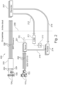
- FIG. 2 illustrates an embodiment of a video production system 200 according to the present disclosure.
- the heart of the video production system 200 is a video production server 201 which receives the camera streams of the high usage cameras 103 via wired and/or wireless data connections 202, e.g. according to the SDI or ST 2110 standard.
- Such video production server is commercially available for instance from EVS Broadcast Equipment ® .
- the video production server 201 ingests and stores the camera streams from the high usage cameras 103.
- the video production server 201 provides for mixing functionalities to integrate different camera streams and/or video clips to generate a program output stream PO.
- For big events with many cameras 103 multiple video production servers 201 can share the tasks to make the video production. For the sake of simplicity, it is assumed in the following that there is only one video production server 201.
- the low usage cameras 104 are connected with an encoder 203 via wired and/or wireless data connections 204.
- the encoder 203 outputs the camera streams of the low usage cameras 104 as encoded data streams.
- the term "encoded” is to be understood in a broad sense and encompasses e.g. compressed data streams.
- the camera streams are encoded for example as SRT (secure reliable transport) streams. However, any other suitable transport standard can be used as well.
- the encoded data streams are transferred via data connections 206 to a cloud recorder 207 that ingests and stores the encoded camera streams.
- a vertical dashed line 208 separates devices on site of the video production and in the cloud. Devices on the left side of the dashed line 208 are on site while the cloud recorder 207 on the right hand side of the dashed line 208 is implemented in the cloud.
- a replay device 211 is connected to the cloud recorder 207 by a data connection 212. In this way the replay device 211 has access to all stored camera streams from the cameras 104.
- the camera streams are provided as low data rate streams in the range of 1 to 10 MB per second per camera stream by the cloud recorder.
- the replay device 211 enables an operator to browse through camera streams recorded on the cloud recorder 207.
- the operator finds a recorded video clip, the operator defines an entry and exit point for the clip and sends this as a command to a media workflow management device 213 that essentially is a single entry point to orchestrate and monitor media files as they move through the live production.
- the media workflow management device 213 sends a command to an access and transcoder device 214 that receives the selected video clip via a data connection 216 as a high data rate data stream in the range of 50 to 800 MB per second.
- the access and transcoder device 214 transcodes the selected video clip to facilitate its integration into the program output stream by the video production server 201.
- the access and transcoder device 214 is connected by a data connection 218 with the video production server 201.
- the selected camera stream is transferred entirely to the video production server 201.
- the editing of the camera stream is then performed on the video production server. I.e. the entry and the exit (beginning and ending) of the video clip is defined on the selected camera stream stored on the video production server.
- the cloud recorder 207 can be rented on an as needed basis in terms of duration and capacity. I.e. if many camera streams from low usage cameras 104 need to be recorded, the cloud recorder 207 can be scaled accordingly. Therefore, the broadcaster does not the need to provide for a lot of hardware that can handle storage and processing capabilities for big events when such events only occur from time to time. This is an important cost advantage for the broadcaster.
- the video production system 200 enables an adapted method for video production.
- the method comprises a first step S1 storing of camera streams on the cloud recorder 207.
- step S2 all recorded camera streams are provided as low data rate streams enabling an operator to browse through all recorded camera streams.
- step S3 the operator selects one recorded camera stream for replay. Finally, the selected camera stream is provided as a high data rate stream to a video production server.
Landscapes
- Engineering & Computer Science (AREA)
- Multimedia (AREA)
- Signal Processing (AREA)
- Databases & Information Systems (AREA)
- Human Computer Interaction (AREA)
- Television Signal Processing For Recording (AREA)
- Two-Way Televisions, Distribution Of Moving Picture Or The Like (AREA)
Abstract
Description
- The present disclosure relates to an integrated video production system and a method for video production.
- In broadcast productions covering an event, e.g. a sports event, multiple cameras capture the event from different perspectives. To this end, there are cameras which are installed at positions where most of the action in the event is expected. Consequently, the camera streams provided by these cameras are frequently used in the program output stream of the video production. Therefore, these cameras are labeled "high usage cameras" in the present application. In addition to the high usage cameras, there are other cameras capturing images from a specific perspective that may be interesting or not depending on how the event evolves. An example of such other cameras is a camera mounted in the cockpit of a racing car capturing the perspective of the racing car driver. It may therefore happen that the camera stream from such camera is not used at all in the production. However, if for instance an accident happens just in front of the racing car capturing the scene, the camera stream from such camera is very interesting and will be used in the production. Consequently, these cameras are labeled "low usage cameras" in the present application to distinguish them from the high usage cameras. Since it is unpredictable whether the camera stream of a low usage camera will be important for the production or not it is necessary to record all camera streams of the low usage cameras to enable a replay of the scene which is a valuable contribution to the video production.
- The camera streams of the high usage cameras are typically recorded on a video production server providing integrated video recording capabilities. However, the video production server is a very expensive device and has a limited video recording capacity which in most cases does not allow for recording all camera streams from low usage cameras. Rather, the recording capacity is limited to recording the camera streams from the high usage cameras.
- Taking this as a starting point there is a need for a video production system and a method enabling cost-efficient recording of camera streams from a plurality of high usage and low usage cameras.
- According to a first aspect the present disclosure suggests a video production system comprising a plurality of low usage cameras, a plurality of high usage cameras, and a video production server, which ingests and stores camera streams provided by the plurality of high usage cameras. The system further comprises a cloud recorder. The cloud recorder ingests and stores camera streams provided by the plurality of low usage camera. The cloud recorder is communicatively connected via a first data connection with a replay device enabling an operator to browse through all the recorded camera streams from the plurality of low usage cameras and to select one of the recorded camera streams for replay by sending a corresponding command to the cloud recorder. Furthermore, the cloud recorder is communicatively connected via a second data connection for providing the recorded camera stream that has been selected to the video production server.
- The cloud recorder can be rented on an as needed basis in terms of duration and capacity depending on the covered event. This approach is more cost efficient than providing additional video production servers for storing the camera streams of the low usage cameras on site or in a studio because video production servers are expensive devices.
- The terms "cloud" and "cloud recorder" are to be understood in a broad sense. The term "cloud" may refer to a public cloud service and/or to infrastructure located in a remote data center that is, for example, reserved for the broadcaster and not accessible to the public.
- In an advantageous embodiment the cloud recorder is adapted for transferring the recorded camera streams as low bit rate data streams via the first data connection and for transferring the selected camera stream as a high bit rate data stream via the second data connection.
- The low bit rate data stream has a bit rate of 1 to 10 MB per second per camera stream while the high bit rate camera stream ranges from 50 to 800 MB per second per camera stream. However, the proposed bit rates are only an example, and the present disclosure is not limited to a specific bit rate or range of bit rates.
- It has been found useful to provide for a video encoder for encoding the camera streams of the low usage cameras. An appropriately encoded camera stream can reduce the required bandwidth of data connection for transferring the camera streams.
- In a further advantageous embodiment, the second data connection connects the cloud recorder with a file access and transcoder device receiving a command from the replay device identifying the selected camera stream. The file access and transcoder device downloads the selected camera stream from the cloud recorder.
- In this case it has been found useful when the file access and transcoder device transcodes the downloaded camera stream and transfers it to the video production server.
- Transcoding the downloaded file facilitates the integration of the selected camera stream into the video production because the camera streams from the high usage cameras may have a different format.
- According to a second aspect the present disclosure suggests a method for video production. The method comprises
- storing camera streams on a cloud recorder,
- providing all recorded camera streams as low data rate streams enabling an operator to browse through all recorded camera streams
- selecting one recorded camera stream for replay; and
- providing the selected camera stream as a high data rate stream to a video production server.
- According to a preferred embodiment of the method, the step of selecting a camera stream also involves defining a beginning and ending of the camera stream. Thus, only the portion of the camera stream between the defined beginning and the ending of the video clip is transferred from the cloud recorder to the video production server. This approach limits the data traffic to a necessary minimum.
- Exemplary embodiments of the present disclosure are illustrated in the drawings and are explained in more detail in the following description. In the figures, the same or similar elements are referenced with the same or similar reference signs. It shows:
- Fig. 1
- a schematic illustration of a sports event which is covered by high usage and low usage cameras;
- Fig. 2
- a schematic illustration of an architecture of an integrated video production system according to the present disclosure; and
- Fig. 3
- a flow diagram of a video production method according to the present disclosure.
- In the figures the same or similar components are labelled with the same or similar reference signs.
-
Figure 1 schematically displays a sports event and more particularly a racing event.Figure 1 displays threeracing cars 101 racing on aracing track 102.Cameras 103 are installed along the racing track at the most interesting locations of theracing track 102 such as curves, chicanes or the home stretch. The camera streams of thecameras 103 are included most of the time in a program output stream of the video production. Therefore, thecameras 103 are labeled as high usage cameras. In addition to that, there arecameras 104, which are mounted in theracing cars 101 covering different perspectives from the racing car, for instance the view of the racing car driver. Typically, the camera streams of thecameras 104 mounted on board ofracing cars 101 are used in the video production only if thecamera 104 captures a scene which provides added value to the video production. In other words: Most of the time the camera streams of thecameras 104 are not included in a program output stream. Thus, thecameras 104 are labeled in the present application as "low usage cameras". - It is noted that the important difference between
high usage cameras 103 in thelow usage cameras 104 is not whether the cameras are mobile or stationary or their image resolution but rather the fact to which extent their camera streams are used in the program output stream of the video production. -
Figure 2 illustrates an embodiment of avideo production system 200 according to the present disclosure. The heart of thevideo production system 200 is avideo production server 201 which receives the camera streams of thehigh usage cameras 103 via wired and/orwireless data connections 202, e.g. according to the SDI or ST 2110 standard. Such video production server is commercially available for instance from EVS Broadcast Equipment ®. Thevideo production server 201 ingests and stores the camera streams from thehigh usage cameras 103. Furthermore, thevideo production server 201 provides for mixing functionalities to integrate different camera streams and/or video clips to generate a program output stream PO. For big events withmany cameras 103 multiplevideo production servers 201 can share the tasks to make the video production. For the sake of simplicity, it is assumed in the following that there is only onevideo production server 201. - The
low usage cameras 104 are connected with anencoder 203 via wired and/orwireless data connections 204. Theencoder 203 outputs the camera streams of thelow usage cameras 104 as encoded data streams. The term "encoded" is to be understood in a broad sense and encompasses e.g. compressed data streams. The camera streams are encoded for example as SRT (secure reliable transport) streams. However, any other suitable transport standard can be used as well. The encoded data streams are transferred viadata connections 206 to acloud recorder 207 that ingests and stores the encoded camera streams. InFigure 2 a vertical dashedline 208 separates devices on site of the video production and in the cloud. Devices on the left side of the dashedline 208 are on site while thecloud recorder 207 on the right hand side of the dashedline 208 is implemented in the cloud. - A
replay device 211 is connected to thecloud recorder 207 by adata connection 212. In this way thereplay device 211 has access to all stored camera streams from thecameras 104. The camera streams are provided as low data rate streams in the range of 1 to 10 MB per second per camera stream by the cloud recorder. In this way thereplay device 211 enables an operator to browse through camera streams recorded on thecloud recorder 207. When the operator finds a recorded video clip, the operator defines an entry and exit point for the clip and sends this as a command to a mediaworkflow management device 213 that essentially is a single entry point to orchestrate and monitor media files as they move through the live production. The mediaworkflow management device 213 sends a command to an access andtranscoder device 214 that receives the selected video clip via adata connection 216 as a high data rate data stream in the range of 50 to 800 MB per second. The access andtranscoder device 214 transcodes the selected video clip to facilitate its integration into the program output stream by thevideo production server 201. To this end the access andtranscoder device 214 is connected by adata connection 218 with thevideo production server 201. - In an alternative embodiment the selected camera stream is transferred entirely to the
video production server 201. The editing of the camera stream is then performed on the video production server. I.e. the entry and the exit (beginning and ending) of the video clip is defined on the selected camera stream stored on the video production server. - One important advantage of the architecture of the
video production system 200 according to the present disclosure is the scalability of thecloud recorder 207. The cloud recorder can be rented on an as needed basis in terms of duration and capacity. I.e. if many camera streams fromlow usage cameras 104 need to be recorded, thecloud recorder 207 can be scaled accordingly. Therefore, the broadcaster does not the need to provide for a lot of hardware that can handle storage and processing capabilities for big events when such events only occur from time to time. This is an important cost advantage for the broadcaster. - The
video production system 200 enables an adapted method for video production. The method comprises a first step S1 storing of camera streams on thecloud recorder 207. In step S2 all recorded camera streams are provided as low data rate streams enabling an operator to browse through all recorded camera streams. In step S3 the operator selects one recorded camera stream for replay. Finally, the selected camera stream is provided as a high data rate stream to a video production server.
Claims (7)
- Video production system (200) comprising a plurality of low usage cameras (104), a plurality of high usage cameras (103) and a video production server (201) which ingests and stores camera streams provided by the plurality of high usage cameras (103), wherein the system further comprises a cloud recorder (207),- wherein the cloud recorder (207) ingests and stores camera streams provided by the plurality of low usage cameras (104),- wherein the cloud recorder (207) is communicatively connected via a first data connection (212) with a replay device (211) enabling an operator to browse through all the recorded camera streams from the plurality of low usage cameras (104) and to select one of the recorded camera streams for replay by sending a corresponding command to the cloud recorder (207); and- wherein the cloud recorder (207) is communicatively connected via a second data connection (216) for providing the recorded camera stream that has been selected to the video production server (201).
- Video production system according to claim 1, wherein the cloud recorder (207) is adapted for transferring the recorded camera streams as low bit rate data streams via the first data connection (212) and for transferring the selected camera stream as a high bit rate data stream via the second data connection (216).
- Video production system according to claim 1 or 2, further comprising a video encoder (203) for encoding the camera streams of the low usage cameras (104).
- Video production system according to one of the preceding claims, wherein the second data connection (216) connects the cloud recorder (207) with a file access and transcoder device (214) receiving a command from the replay device (211) identifying the selected camera stream, wherein the file access and transcoder device (214) downloads the selected camera stream from the cloud recorder (207).
- Video production system according to claim 4, wherein the file access and transcoder device (214) transcodes the downloaded camera stream and transfers it to the video production server (201).
- Method for video production system comprising- storing (S1) camera streams on a cloud recorder (207),- providing (S2) all recorded camera streams as low data rate streams enabling an operator to browse through all recorded camera streams,- selecting (S3) one recorded camera stream for replay; and- providing (S4) the selected camera stream as a high data rate stream to a video production server (201).
- Method according to claim 6, wherein selecting a camera stream also involves defining a beginning and ending of the camera stream.
Applications Claiming Priority (1)
| Application Number | Priority Date | Filing Date | Title |
|---|---|---|---|
| EP22194739 | 2022-09-09 |
Publications (3)
| Publication Number | Publication Date |
|---|---|
| EP4336825A1 true EP4336825A1 (en) | 2024-03-13 |
| EP4336825B1 EP4336825B1 (en) | 2025-07-16 |
| EP4336825C0 EP4336825C0 (en) | 2025-07-16 |
Family
ID=83271363
Family Applications (1)
| Application Number | Title | Priority Date | Filing Date |
|---|---|---|---|
| EP23196653.2A Active EP4336825B1 (en) | 2022-09-09 | 2023-09-11 | Integrated video production system and method for video production |
Country Status (2)
| Country | Link |
|---|---|
| US (1) | US20240121461A1 (en) |
| EP (1) | EP4336825B1 (en) |
Citations (6)
| Publication number | Priority date | Publication date | Assignee | Title |
|---|---|---|---|---|
| US20020049979A1 (en) * | 2000-05-18 | 2002-04-25 | Patrick White | Multiple camera video system which displays selected images |
| US20120113264A1 (en) * | 2010-11-10 | 2012-05-10 | Verizon Patent And Licensing Inc. | Multi-feed event viewing |
| US20150215586A1 (en) * | 2014-01-29 | 2015-07-30 | Sensormatic Electronics, LLC | Selection and Display of Adaptive Rate Streams in Video Security System |
| US20170142172A1 (en) * | 2015-11-13 | 2017-05-18 | Le Holdings (Beijing) Co., Ltd. | Video Player for Multiple Cameras, Playing System and Playing Method |
| CN113411647A (en) * | 2021-04-20 | 2021-09-17 | 北京国际云转播科技有限公司 | Cloud director method, system, server and computer readable storage medium |
| US20220231773A1 (en) * | 2019-05-29 | 2022-07-21 | Telefonaktiebolaget Lm Ericsson (Publ) | Replay realization in media production using fifth generation, 5g telecommunication |
-
2023
- 2023-09-07 US US18/462,520 patent/US20240121461A1/en active Pending
- 2023-09-11 EP EP23196653.2A patent/EP4336825B1/en active Active
Patent Citations (6)
| Publication number | Priority date | Publication date | Assignee | Title |
|---|---|---|---|---|
| US20020049979A1 (en) * | 2000-05-18 | 2002-04-25 | Patrick White | Multiple camera video system which displays selected images |
| US20120113264A1 (en) * | 2010-11-10 | 2012-05-10 | Verizon Patent And Licensing Inc. | Multi-feed event viewing |
| US20150215586A1 (en) * | 2014-01-29 | 2015-07-30 | Sensormatic Electronics, LLC | Selection and Display of Adaptive Rate Streams in Video Security System |
| US20170142172A1 (en) * | 2015-11-13 | 2017-05-18 | Le Holdings (Beijing) Co., Ltd. | Video Player for Multiple Cameras, Playing System and Playing Method |
| US20220231773A1 (en) * | 2019-05-29 | 2022-07-21 | Telefonaktiebolaget Lm Ericsson (Publ) | Replay realization in media production using fifth generation, 5g telecommunication |
| CN113411647A (en) * | 2021-04-20 | 2021-09-17 | 北京国际云转播科技有限公司 | Cloud director method, system, server and computer readable storage medium |
Also Published As
| Publication number | Publication date |
|---|---|
| EP4336825B1 (en) | 2025-07-16 |
| EP4336825C0 (en) | 2025-07-16 |
| US20240121461A1 (en) | 2024-04-11 |
Similar Documents
| Publication | Publication Date | Title |
|---|---|---|
| US10204657B2 (en) | Image processing apparatus, image processing method, and recording medium | |
| US9247317B2 (en) | Content streaming with client device trick play index | |
| US20220360832A1 (en) | High-quality, reduced data rate streaming video production and monitoring system | |
| EP1871098A2 (en) | Processing of removable media that stores full frame video & sub-frame metadata | |
| JP2010166622A (en) | Apparatus for receiving digital information signal | |
| CN1496116A (en) | Digital video cassette recorder capable of playing back according to non-standard speed | |
| CN103442207A (en) | Stage dispatching video monitoring system based on IP networking | |
| US20090278941A1 (en) | Multi-channel streaming device and related method | |
| CN115336282A (en) | Real-time video production system, real-time video production method and cloud server | |
| CN103108217A (en) | Method, apparatus and system for prioritising content for distribution | |
| CN114630051A (en) | Video processing method and system | |
| US6798756B1 (en) | Data transmission system and method, and data receiving method and device | |
| EP4336825B1 (en) | Integrated video production system and method for video production | |
| US7729425B2 (en) | Image processing apparatus and method, program, and recording medium | |
| EP1095507B1 (en) | Gathering and editing information with a camera | |
| Kim et al. | Overview of Cloud-Based High Quality Media Production System | |
| US20050084008A1 (en) | Image processing apparatus and method, information processing apparatus and method, program, recording medium, and information processing system | |
| KR20020006983A (en) | Methods and its System for Broadcasting Through Internet | |
| WO2010020890A1 (en) | Receiving device | |
| JPWO2018092173A1 (en) | Remote video processing system | |
| HK1116967A (en) | Processing of removable media that stores full frame video & sub-frame metadata | |
| HK1115702A1 (en) | Sub-frame metadata distribution server |
Legal Events
| Date | Code | Title | Description |
|---|---|---|---|
| PUAI | Public reference made under article 153(3) epc to a published international application that has entered the european phase |
Free format text: ORIGINAL CODE: 0009012 |
|
| STAA | Information on the status of an ep patent application or granted ep patent |
Free format text: STATUS: THE APPLICATION HAS BEEN PUBLISHED |
|
| AK | Designated contracting states |
Kind code of ref document: A1 Designated state(s): AL AT BE BG CH CY CZ DE DK EE ES FI FR GB GR HR HU IE IS IT LI LT LU LV MC ME MK MT NL NO PL PT RO RS SE SI SK SM TR |
|
| STAA | Information on the status of an ep patent application or granted ep patent |
Free format text: STATUS: REQUEST FOR EXAMINATION WAS MADE |
|
| 17P | Request for examination filed |
Effective date: 20240913 |
|
| RBV | Designated contracting states (corrected) |
Designated state(s): AL AT BE BG CH CY CZ DE DK EE ES FI FR GB GR HR HU IE IS IT LI LT LU LV MC ME MK MT NL NO PL PT RO RS SE SI SK SM TR |
|
| GRAP | Despatch of communication of intention to grant a patent |
Free format text: ORIGINAL CODE: EPIDOSNIGR1 |
|
| STAA | Information on the status of an ep patent application or granted ep patent |
Free format text: STATUS: GRANT OF PATENT IS INTENDED |
|
| RIC1 | Information provided on ipc code assigned before grant |
Ipc: H04N 21/431 20110101ALI20250408BHEP Ipc: H04N 21/2343 20110101ALI20250408BHEP Ipc: H04N 21/6587 20110101ALI20250408BHEP Ipc: H04N 21/2747 20110101ALI20250408BHEP Ipc: H04N 21/2187 20110101ALI20250408BHEP Ipc: H04N 21/218 20110101ALI20250408BHEP Ipc: H04N 7/18 20060101AFI20250408BHEP |
|
| INTG | Intention to grant announced |
Effective date: 20250422 |
|
| GRAS | Grant fee paid |
Free format text: ORIGINAL CODE: EPIDOSNIGR3 |
|
| GRAA | (expected) grant |
Free format text: ORIGINAL CODE: 0009210 |
|
| STAA | Information on the status of an ep patent application or granted ep patent |
Free format text: STATUS: THE PATENT HAS BEEN GRANTED |
|
| AK | Designated contracting states |
Kind code of ref document: B1 Designated state(s): AL AT BE BG CH CY CZ DE DK EE ES FI FR GB GR HR HU IE IS IT LI LT LU LV MC ME MK MT NL NO PL PT RO RS SE SI SK SM TR |
|
| REG | Reference to a national code |
Ref country code: GB Ref legal event code: FG4D |
|
| REG | Reference to a national code |
Ref country code: CH Ref legal event code: EP |
|
| REG | Reference to a national code |
Ref country code: IE Ref legal event code: FG4D |
|
| U01 | Request for unitary effect filed |
Effective date: 20250716 |
|
| U07 | Unitary effect registered |
Designated state(s): AT BE BG DE DK EE FI FR IT LT LU LV MT NL PT RO SE SI Effective date: 20250722 |
|
| U20 | Renewal fee for the european patent with unitary effect paid |
Year of fee payment: 3 Effective date: 20250723 |
|
| PG25 | Lapsed in a contracting state [announced via postgrant information from national office to epo] |
Ref country code: IS Free format text: LAPSE BECAUSE OF FAILURE TO SUBMIT A TRANSLATION OF THE DESCRIPTION OR TO PAY THE FEE WITHIN THE PRESCRIBED TIME-LIMIT Effective date: 20251116 |
|
| PG25 | Lapsed in a contracting state [announced via postgrant information from national office to epo] |
Ref country code: NO Free format text: LAPSE BECAUSE OF FAILURE TO SUBMIT A TRANSLATION OF THE DESCRIPTION OR TO PAY THE FEE WITHIN THE PRESCRIBED TIME-LIMIT Effective date: 20251016 |
|
| PG25 | Lapsed in a contracting state [announced via postgrant information from national office to epo] |
Ref country code: HR Free format text: LAPSE BECAUSE OF FAILURE TO SUBMIT A TRANSLATION OF THE DESCRIPTION OR TO PAY THE FEE WITHIN THE PRESCRIBED TIME-LIMIT Effective date: 20250716 |
|
| PG25 | Lapsed in a contracting state [announced via postgrant information from national office to epo] |
Ref country code: GR Free format text: LAPSE BECAUSE OF FAILURE TO SUBMIT A TRANSLATION OF THE DESCRIPTION OR TO PAY THE FEE WITHIN THE PRESCRIBED TIME-LIMIT Effective date: 20251017 |
|
| PG25 | Lapsed in a contracting state [announced via postgrant information from national office to epo] |
Ref country code: PL Free format text: LAPSE BECAUSE OF FAILURE TO SUBMIT A TRANSLATION OF THE DESCRIPTION OR TO PAY THE FEE WITHIN THE PRESCRIBED TIME-LIMIT Effective date: 20250716 |
|
| PG25 | Lapsed in a contracting state [announced via postgrant information from national office to epo] |
Ref country code: RS Free format text: LAPSE BECAUSE OF FAILURE TO SUBMIT A TRANSLATION OF THE DESCRIPTION OR TO PAY THE FEE WITHIN THE PRESCRIBED TIME-LIMIT Effective date: 20251016 |
|
| PG25 | Lapsed in a contracting state [announced via postgrant information from national office to epo] |
Ref country code: ES Free format text: LAPSE BECAUSE OF FAILURE TO SUBMIT A TRANSLATION OF THE DESCRIPTION OR TO PAY THE FEE WITHIN THE PRESCRIBED TIME-LIMIT Effective date: 20250716 |
|
| PG25 | Lapsed in a contracting state [announced via postgrant information from national office to epo] |
Ref country code: SM Free format text: LAPSE BECAUSE OF FAILURE TO SUBMIT A TRANSLATION OF THE DESCRIPTION OR TO PAY THE FEE WITHIN THE PRESCRIBED TIME-LIMIT Effective date: 20250716 |
|
| PG25 | Lapsed in a contracting state [announced via postgrant information from national office to epo] |
Ref country code: CZ Free format text: LAPSE BECAUSE OF FAILURE TO SUBMIT A TRANSLATION OF THE DESCRIPTION OR TO PAY THE FEE WITHIN THE PRESCRIBED TIME-LIMIT Effective date: 20250716 |
|
| PG25 | Lapsed in a contracting state [announced via postgrant information from national office to epo] |
Ref country code: SK Free format text: LAPSE BECAUSE OF FAILURE TO SUBMIT A TRANSLATION OF THE DESCRIPTION OR TO PAY THE FEE WITHIN THE PRESCRIBED TIME-LIMIT Effective date: 20250716 |