EP4336816A1 - Image forming apparatus, image forming program, and image forming method - Google Patents
Image forming apparatus, image forming program, and image forming method Download PDFInfo
- Publication number
- EP4336816A1 EP4336816A1 EP23163619.2A EP23163619A EP4336816A1 EP 4336816 A1 EP4336816 A1 EP 4336816A1 EP 23163619 A EP23163619 A EP 23163619A EP 4336816 A1 EP4336816 A1 EP 4336816A1
- Authority
- EP
- European Patent Office
- Prior art keywords
- image forming
- data
- defect
- processing
- case
- Prior art date
- Legal status (The legal status is an assumption and is not a legal conclusion. Google has not performed a legal analysis and makes no representation as to the accuracy of the status listed.)
- Granted
Links
Images


Classifications
-
- H—ELECTRICITY
- H04—ELECTRIC COMMUNICATION TECHNIQUE
- H04N—PICTORIAL COMMUNICATION, e.g. TELEVISION
- H04N1/00—Scanning, transmission or reproduction of documents or the like, e.g. facsimile transmission; Details thereof
- H04N1/00002—Diagnosis, testing or measuring; Detecting, analysing or monitoring not otherwise provided for
- H04N1/00026—Methods therefor
- H04N1/00039—Analysis, i.e. separating and studying components of a greater whole
-
- H—ELECTRICITY
- H04—ELECTRIC COMMUNICATION TECHNIQUE
- H04N—PICTORIAL COMMUNICATION, e.g. TELEVISION
- H04N1/00—Scanning, transmission or reproduction of documents or the like, e.g. facsimile transmission; Details thereof
- H04N1/44—Secrecy systems
- H04N1/4446—Hiding of documents or document information
-
- G—PHYSICS
- G06—COMPUTING OR CALCULATING; COUNTING
- G06F—ELECTRIC DIGITAL DATA PROCESSING
- G06F21/00—Security arrangements for protecting computers, components thereof, programs or data against unauthorised activity
- G06F21/60—Protecting data
- G06F21/606—Protecting data by securing the transmission between two devices or processes
- G06F21/608—Secure printing
-
- H—ELECTRICITY
- H04—ELECTRIC COMMUNICATION TECHNIQUE
- H04N—PICTORIAL COMMUNICATION, e.g. TELEVISION
- H04N1/00—Scanning, transmission or reproduction of documents or the like, e.g. facsimile transmission; Details thereof
- H04N1/00002—Diagnosis, testing or measuring; Detecting, analysing or monitoring not otherwise provided for
- H04N1/00005—Diagnosis, testing or measuring; Detecting, analysing or monitoring not otherwise provided for relating to image data
-
- H—ELECTRICITY
- H04—ELECTRIC COMMUNICATION TECHNIQUE
- H04N—PICTORIAL COMMUNICATION, e.g. TELEVISION
- H04N1/00—Scanning, transmission or reproduction of documents or the like, e.g. facsimile transmission; Details thereof
- H04N1/00002—Diagnosis, testing or measuring; Detecting, analysing or monitoring not otherwise provided for
- H04N1/00026—Methods therefor
-
- H—ELECTRICITY
- H04—ELECTRIC COMMUNICATION TECHNIQUE
- H04N—PICTORIAL COMMUNICATION, e.g. TELEVISION
- H04N1/00—Scanning, transmission or reproduction of documents or the like, e.g. facsimile transmission; Details thereof
- H04N1/00002—Diagnosis, testing or measuring; Detecting, analysing or monitoring not otherwise provided for
- H04N1/00026—Methods therefor
- H04N1/00034—Measuring, i.e. determining a quantity by comparison with a standard
-
- H—ELECTRICITY
- H04—ELECTRIC COMMUNICATION TECHNIQUE
- H04N—PICTORIAL COMMUNICATION, e.g. TELEVISION
- H04N1/00—Scanning, transmission or reproduction of documents or the like, e.g. facsimile transmission; Details thereof
- H04N1/00002—Diagnosis, testing or measuring; Detecting, analysing or monitoring not otherwise provided for
- H04N1/00026—Methods therefor
- H04N1/0005—Methods therefor in service, i.e. during normal operation
-
- H—ELECTRICITY
- H04—ELECTRIC COMMUNICATION TECHNIQUE
- H04N—PICTORIAL COMMUNICATION, e.g. TELEVISION
- H04N1/00—Scanning, transmission or reproduction of documents or the like, e.g. facsimile transmission; Details thereof
- H04N1/00002—Diagnosis, testing or measuring; Detecting, analysing or monitoring not otherwise provided for
- H04N1/00071—Diagnosis, testing or measuring; Detecting, analysing or monitoring not otherwise provided for characterised by the action taken
- H04N1/00074—Indicating or reporting
-
- H—ELECTRICITY
- H04—ELECTRIC COMMUNICATION TECHNIQUE
- H04N—PICTORIAL COMMUNICATION, e.g. TELEVISION
- H04N1/00—Scanning, transmission or reproduction of documents or the like, e.g. facsimile transmission; Details thereof
- H04N1/00002—Diagnosis, testing or measuring; Detecting, analysing or monitoring not otherwise provided for
- H04N1/00071—Diagnosis, testing or measuring; Detecting, analysing or monitoring not otherwise provided for characterised by the action taken
- H04N1/00082—Adjusting or controlling
-
- H—ELECTRICITY
- H04—ELECTRIC COMMUNICATION TECHNIQUE
- H04N—PICTORIAL COMMUNICATION, e.g. TELEVISION
- H04N1/00—Scanning, transmission or reproduction of documents or the like, e.g. facsimile transmission; Details thereof
- H04N1/00002—Diagnosis, testing or measuring; Detecting, analysing or monitoring not otherwise provided for
- H04N1/00071—Diagnosis, testing or measuring; Detecting, analysing or monitoring not otherwise provided for characterised by the action taken
- H04N1/0009—Storage
-
- H—ELECTRICITY
- H04—ELECTRIC COMMUNICATION TECHNIQUE
- H04N—PICTORIAL COMMUNICATION, e.g. TELEVISION
- H04N1/00—Scanning, transmission or reproduction of documents or the like, e.g. facsimile transmission; Details thereof
- H04N1/00838—Preventing unauthorised reproduction
- H04N1/00856—Preventive measures
- H04N1/00864—Modifying the reproduction, e.g. outputting a modified copy of a scanned original
- H04N1/00867—Modifying the reproduction, e.g. outputting a modified copy of a scanned original with additional data, e.g. by adding a warning message
- H04N1/0087—Modifying the reproduction, e.g. outputting a modified copy of a scanned original with additional data, e.g. by adding a warning message with hidden additional data, e.g. data invisible to the human eye
-
- H—ELECTRICITY
- H04—ELECTRIC COMMUNICATION TECHNIQUE
- H04N—PICTORIAL COMMUNICATION, e.g. TELEVISION
- H04N1/00—Scanning, transmission or reproduction of documents or the like, e.g. facsimile transmission; Details thereof
- H04N1/387—Composing, repositioning or otherwise geometrically modifying originals
-
- H—ELECTRICITY
- H04—ELECTRIC COMMUNICATION TECHNIQUE
- H04N—PICTORIAL COMMUNICATION, e.g. TELEVISION
- H04N1/00—Scanning, transmission or reproduction of documents or the like, e.g. facsimile transmission; Details thereof
- H04N1/44—Secrecy systems
-
- H—ELECTRICITY
- H04—ELECTRIC COMMUNICATION TECHNIQUE
- H04N—PICTORIAL COMMUNICATION, e.g. TELEVISION
- H04N2201/00—Indexing scheme relating to scanning, transmission or reproduction of documents or the like, and to details thereof
- H04N2201/0077—Types of the still picture apparatus
- H04N2201/0094—Multifunctional device, i.e. a device capable of all of reading, reproducing, copying, facsimile transception, file transception
Definitions
- the present disclosure relates to an image forming apparatus, an image forming program, and an image forming method.
- JP2012-51296A discloses an image forming apparatus that includes image data conversion unit that converts print data into print image data in a printing apparatus that prints out the print data received from a higher-level apparatus.
- the image data conversion unit includes a text data replacement unit, the image data conversion unit determines whether or not an instruction about a replacement mode of text data is given, and the text data conversion unit generates a random text code by a random number, and generates the print image data by text font data corresponding to the generated text code in a case where the replacement mode is set.
- An object of the present disclosure is to provide an image forming apparatus, an image forming program, and an image forming method capable of efficiently performing analysis of a defect as compared with a case where image forming data in which confidential data is replaced with another data is used as defect analysis data as it is without executing image forming processing of the image forming data in a case where a defect occurs in image forming processing of image forming data including confidential data.
- an image forming apparatus including a processor configured to generate second image forming data for defect analysis in which confidential data included in first image forming data is invisible in a case where a defect occurs in image forming processing of the first image forming data, execute the image forming processing for the generated second image forming data, and output defect analysis data corresponding to a processing result of the image forming processing executed for the second image forming data.
- the image forming apparatus of the first aspect in which the processor may be configured to output the defect analysis data including the second image forming data in a case where the defect is reproduced in the image forming processing of the second image forming data.
- the image forming apparatus of the first aspect in which the processor may be configured to output the defect analysis data including difference data indicating a difference between the first image forming data and the second image forming data and the second image forming data in a case where the defect is not reproduced in the image forming processing of the second image forming data.
- the image forming apparatus of the third aspect in which the processor may be configured to output the defect analysis data further including a processing result of the image forming processing of the first image forming data.
- the image forming apparatus of any one of the second aspect to the fourth aspect, in which the processor may be configured to specify whether or not the defect is reproduced by using a comparison result between log data recorded in the image forming processing of the first image forming data and log data recorded in the image forming processing of the second image forming data.
- the image forming apparatus of any one of the second aspect to the fifth aspect, in which the confidential data may be personal data that is able to specify a person.
- an image forming program causing a computer to execute generating second image forming data for defect analysis in which confidential data included in first image forming data is invisible in a case where a defect occurs in image forming processing of the first image forming data, executing the image forming processing for the generated second image forming data, and outputting defect analysis data corresponding to a processing result of the image forming processing executed for the second image forming data.
- an image forming method including generating second image forming data for defect analysis in which confidential data included in first image forming data is invisible in a case where a defect occurs in image forming processing of the first image forming data, executing the image forming processing for the generated second image forming data, and outputting defect analysis data corresponding to a processing result of the image forming processing executed for the second image forming data.
- the analysis of the defect may be efficiently performed as compared with a case where the image forming data in which the confidential data is replaced with another data is used as the defect analysis data as it is without executing the image forming processing of the image forming data in a case where the defect occurs in the image forming processing of the image forming data including the confidential data.
- the analysis of the defect may be efficiently performed as compared with a case where the defect analysis data does not include the second image forming data.
- the analysis of the defect may be efficiently performed as compared with a case where the defect analysis data does not include the difference data indicating the difference between the first image forming data and the second image forming data and the second image forming data.
- the analysis of the defect may be efficiently performed as compared with a case where the defect analysis data does not include the processing result of the image forming processing of the first image forming data.
- the accuracy of specifying whether or not the defect is reproduced can be improved as compared with a case where it is specified whether or not the defect is reproduced without using the comparison result between the log data recorded in the image forming processing of the first image forming data and the log data recorded in the image forming processing of the second image forming data.
- Fig. 1 illustrates a schematic configuration of an image forming apparatus 10 according to the present exemplary embodiment.
- the image forming apparatus 10 includes a computer 20.
- the computer 20 has a configuration in which a central processing unit (CPU) 20A, a read only memory (ROM) 20B, a random access memory (RAM) 20C, and an input and output interface (I/O) 20D are connected to each other via a bus 20E.
- the CPU 20A is an example of a processor.
- Functional units such as an operation display unit 21, an image scanning unit 22, an image forming unit 23, a sheet supply unit 24, a sheet ejection unit 25, a network communication interface (I/F) 26, a telephone line communication interface (I/F) 27, and a storage unit 28 are connected to the I/O 20D.
- the operation display unit 21 includes, for example, various buttons such as a start button for instructing the start of copying and a ten-key, a setting screen for setting various image forming conditions such as copy density, and a touch panel for displaying various screens of a state of an apparatus and like, and the like.
- the image scanning unit 22 includes an image scanning sensor such as a line CCD and a scanning mechanism for scanning the image scanning sensor, and has a function as a so-called scanner that scans an image of a document set in the apparatus.
- the image forming unit 23 has a function of forming an image on a recording medium, for example, by a so-called electrophotographic method.
- the image forming unit 23 includes a charging device that charges a photoconductor drum, an exposure device that forms an electrostatic latent image corresponding to an image on the photoconductor drum by exposing the charged photoconductor drum with light corresponding to the image, a developing device that develops the electrostatic latent image formed on the photoconductor drum with toner, and a transfer device that transfers a toner image corresponding to the image formed on the photoconductor drum to a recording medium, and a fixing device that fixes the toner image corresponding to the image transferred to the recording medium.
- the exposure device examples include an optical scanning device including an optical system such as a semiconductor laser, a rotating polymorphic mirror, a collimator lens, a cylindrical lens, and an f ⁇ lens, or an LED head including a plurality of LEDs.
- the image forming unit 23 may be configured to form the image on the recording medium by an inkjet recording method.
- the sheet supply unit 24 includes a sheet tray in which a recording sheet is stored, a supply mechanism for supplying the recording sheet from the sheet tray to the image forming unit 23, and the like.
- the sheet ejection unit 25 includes an ejection tray from which the recording sheet is ejected, an ejection mechanism for ejecting the recording sheet on which the image is formed by the image forming unit 23 onto the ejection tray, and the like.
- the network communication interface I/F 26 is an interface for performing data communication with an external apparatus via a network (not shown).
- the telephone line communication interface I/F 27 is an interface for performing facsimile communication with another image forming apparatus connected via a telephone line (not shown).
- the storage unit 28 stores log data 28D related to various processing results such as copying, facsimile communication, and printing, and an image forming program 28P to be described later.
- the image forming program 28P may be stored in a non-volatile non-transitory recording medium, may be distributed via a network, and may be appropriately installed in the image forming apparatus 10.
- non-volatile non-transitory recording medium examples include a compact disc read only memory (CD-ROM), a magneto-optical disc, an HDD, a digital versatile disc read only memory (DVD-ROM), a flash memory, a memory card, and the like.
- CD-ROM compact disc read only memory
- DVD-ROM digital versatile disc read only memory
- flash memory a memory card, and the like.
- step S100 the CPU 20A determines whether or not first image forming data is received.
- the first image forming data includes data such as text and an image to be printed on the recording sheet, and is transmitted from, for example, an external apparatus via the network communication interface I/F 26.
- the CPU proceeds to step S101, and in a case where the first image forming data is not received, the CPU waits until the first image forming data is received.
- step S101 the CPU 20A executes the image forming processing based on the first image forming data received in step S101.
- the image forming unit 23 is controlled such that the image is formed on the recording sheet based on the first image forming data received in step S101.
- the log data 28D in the image forming processing is stored in the storage unit 28.
- the log data includes a processing result of each processing of a series of processing in the image forming processing, the presence or absence of occurrence of a defect, the content of the defect in a case where the defect occurs, and the like.
- the defect includes, for example, various defects such as a defect that occurs in various kinds of image processing performed on the received first image forming data, a defect that occurs in sheet supply processing in the sheet supply unit 24, and a defect that occurs in the image forming processing in the image forming unit 23, and a defect that occurs in a sheet ejection processing in the sheet ejection unit 25.
- step S102 the CPU 20A determines whether or not the defect occurs in the image forming processing of step S101. In a case where the defect occurs in the image forming processing in step S101, the CPU proceeds to step S103, and in a case where the defect does not occur, the CPU ends this routine.
- the CPU 20A determines whether or not the first image forming data includes confidential data.
- the confidential data is data not to be disclosed to an unspecified person.
- the confidential data include personal data.
- the personal data is information that can specify a person, and includes at least one piece of information such as a name, an address, or a telephone number.
- various known methods can be used as a method for determining whether or not the first image forming data includes the confidential data, in a case where the confidential data is personal data, for example, the CPU determines whether or not at least one piece of information such as a name, an address, or a telephone number is included in the first image forming data.
- the confidential data is not limited to the personal data, and may be, for example, external confidential data in a company.
- step S104 the CPU proceeds to step S104, and in a case where the first image forming data does not include the confidential data, the CPU proceeds to step S106.
- the CPU 20A generates second image forming data.
- the second image forming data is defect analysis data in which the confidential data included in the first image forming data received in step S101 is invisible.
- the personal data is replaced with replacement data that does not cause a problem even though the personal data is disclosed to an unspecified person.
- the second image forming data is generated such that an image G2 obtained by replacing the personal data KD with replacement data CD.
- Various known methods can be used as the replacement method, and for example, the method described in JP2012-51296A can be used.
- the personal data may be deleted instead of replacing the personal data with the replacement data.
- step S105 the CPU 20A executes the image forming processing based on the second image forming data in the same manner as in step S101, and stores the log data 28D in the image forming processing in the storage unit 28.
- step S106 the CPU 20A outputs, as the defect analysis data, the first image forming data received in step S101.
- the CPU 20A may output the defect analysis data to the storage unit 28 and may store the data, or may transmit the data to an external apparatus via the network communication interface I/F 26.
- step S107 the CPU 20A determines whether or not the defect is reproduced, that is, whether or not a similar defect in a case where it is determined that the defect occurs in step S102 occurs. Specifically, for example, it is specified whether or not the defect is reproduced by using a comparison result between the log data recorded in the image forming processing of the first image forming data and the log data recorded in the image forming processing of the second image forming data. More specifically, for example, it is assumed that the defect is reproduced in a case where comparison results between pieces of log data in a past predetermined period including a point in time when the defect occurs match. In a case where the defect is reproduced, the CPU proceeds to step S108, and in a case where the defect is not reproduced, the CPU proceeds to step S109.
- step S108 the CPU 20A outputs, as the defect analysis data, the second image forming data generated in step S104.
- the CPU 20A may output the defect analysis data to the storage unit 28 and may store the data, or may transmit the data to an external apparatus via the network communication interface I/F 26.
- the second image forming data in which the confidential data is replaced with the replacement data is output. That is, the second image forming data for which it is determined that the defect is reproduced is output.
- the analysis of the defect may be performed efficiently.
- step S 109 the CPU 20A generates difference data representing a difference between the first image forming data received in step S101 and the second image forming data generated in step S104.
- the difference data is data including the confidential data included in the first image forming data and the replacement data with which the confidential data is replaced. That is, the difference data is data indicating which data of the first image forming data is changed and how.
- step S 110 the CPU 20A outputs the log data that is the processing result of the image forming processing of the first image forming data executed in step S101, the difference data generated in step S109, and the defect analysis data including the second image forming data generated in step S104.
- the CPU 20A may output the defect analysis data to the storage unit 28 and may store the data, or may transmit the data to an external apparatus via the network communication interface I/F 26.
- the defect may be efficiently analyzed on the side on which the defect is analyzed.
- the defect analysis data including the log data which is the processing result of the image forming processing of the first image forming data, the difference data, and the second image forming data may be output without including the log data which is the processing result of the image forming processing of the first image forming data.
- the processing performed by executing the program stored in the storage unit has been described, the processing of the program may be realized by hardware.
- the processing in the above-described exemplary embodiment may be stored as a program in a storage medium such as an optical disk and may be distributed.
- processor refers to hardware in a broad sense.
- Examples of the processor include general processors (e.g., CPU: Central Processing Unit) and dedicated processors (e.g., GPU: Graphics Processing Unit, ASIC: Application Specific Integrated Circuit, FPGA: Field Programmable Gate Array, and programmable logic device).
- processor is broad enough to encompass one processor or plural processors in collaboration which are located physically apart from each other but may work cooperatively.
- the order of operations of the processor is not limited to one described in the embodiments above, and may be changed.
Landscapes
- Engineering & Computer Science (AREA)
- Multimedia (AREA)
- Signal Processing (AREA)
- Health & Medical Sciences (AREA)
- General Health & Medical Sciences (AREA)
- Biomedical Technology (AREA)
- Computer Security & Cryptography (AREA)
- Theoretical Computer Science (AREA)
- Computer Hardware Design (AREA)
- Software Systems (AREA)
- Physics & Mathematics (AREA)
- General Engineering & Computer Science (AREA)
- General Physics & Mathematics (AREA)
- Bioethics (AREA)
- Accessory Devices And Overall Control Thereof (AREA)
- Control Or Security For Electrophotography (AREA)
- Facsimiles In General (AREA)
Abstract
Description
- The present disclosure relates to an image forming apparatus, an image forming program, and an image forming method.
-
JP2012-51296A - An object of the present disclosure is to provide an image forming apparatus, an image forming program, and an image forming method capable of efficiently performing analysis of a defect as compared with a case where image forming data in which confidential data is replaced with another data is used as defect analysis data as it is without executing image forming processing of the image forming data in a case where a defect occurs in image forming processing of image forming data including confidential data.
- According to a first aspect of the present disclosure, there is provided an image forming apparatus including a processor configured to generate second image forming data for defect analysis in which confidential data included in first image forming data is invisible in a case where a defect occurs in image forming processing of the first image forming data, execute the image forming processing for the generated second image forming data, and output defect analysis data corresponding to a processing result of the image forming processing executed for the second image forming data.
- According to a second aspect of the present disclosure, there is provided the image forming apparatus of the first aspect, in which the processor may be configured to output the defect analysis data including the second image forming data in a case where the defect is reproduced in the image forming processing of the second image forming data.
- According to a third aspect of the present disclosure, there is provided the image forming apparatus of the first aspect, in which the processor may be configured to output the defect analysis data including difference data indicating a difference between the first image forming data and the second image forming data and the second image forming data in a case where the defect is not reproduced in the image forming processing of the second image forming data.
- According to a fourth aspect of the present disclosure, there is provided the image forming apparatus of the third aspect, in which the processor may be configured to output the defect analysis data further including a processing result of the image forming processing of the first image forming data.
- According to a fifth aspect of the present disclosure, there is provided the image forming apparatus of any one of the second aspect to the fourth aspect, in which the processor may be configured to specify whether or not the defect is reproduced by using a comparison result between log data recorded in the image forming processing of the first image forming data and log data recorded in the image forming processing of the second image forming data.
- According to a sixth aspect of the present disclosure, there is provided the image forming apparatus of any one of the second aspect to the fifth aspect, in which the confidential data may be personal data that is able to specify a person.
- According to a seventh aspect of the present disclosure, there is provided an image forming program causing a computer to execute generating second image forming data for defect analysis in which confidential data included in first image forming data is invisible in a case where a defect occurs in image forming processing of the first image forming data, executing the image forming processing for the generated second image forming data, and outputting defect analysis data corresponding to a processing result of the image forming processing executed for the second image forming data.
- According to an eighth aspect of the present disclosure, there is provided an image forming method including generating second image forming data for defect analysis in which confidential data included in first image forming data is invisible in a case where a defect occurs in image forming processing of the first image forming data, executing the image forming processing for the generated second image forming data, and outputting defect analysis data corresponding to a processing result of the image forming processing executed for the second image forming data.
- According to the first aspect, the seventh aspect, and the eighth aspect, there is an effect that the analysis of the defect may be efficiently performed as compared with a case where the image forming data in which the confidential data is replaced with another data is used as the defect analysis data as it is without executing the image forming processing of the image forming data in a case where the defect occurs in the image forming processing of the image forming data including the confidential data.
- According to the second aspect, there is an effect that the analysis of the defect may be efficiently performed as compared with a case where the defect analysis data does not include the second image forming data.
- According to the third aspect, there is an effect that the analysis of the defect may be efficiently performed as compared with a case where the defect analysis data does not include the difference data indicating the difference between the first image forming data and the second image forming data and the second image forming data.
- According to the fourth aspect, there is an effect that the analysis of the defect may be efficiently performed as compared with a case where the defect analysis data does not include the processing result of the image forming processing of the first image forming data.
- According to the fifth aspect, there is an effect that the accuracy of specifying whether or not the defect is reproduced can be improved as compared with a case where it is specified whether or not the defect is reproduced without using the comparison result between the log data recorded in the image forming processing of the first image forming data and the log data recorded in the image forming processing of the second image forming data.
- According to the sixth aspect, there is an effect that the leakage of the personal data may be suppressed.
- Exemplary embodiment(s) of the present invention will be described in detail based on the following figures, wherein:
-
Fig. 1 is a diagram illustrating a schematic configuration of an image forming apparatus; -
Fig. 2 is a flowchart showing an example of image forming processing; -
Fig. 3 is a diagram showing an example of an image formed on a recording sheet based on first image forming data; and -
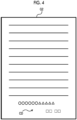
Fig. 4 is a diagram showing an example of an image formed on a recording sheet based on second image forming data. - Hereinafter, an example of an exemplary embodiment for implementing a technology of the present disclosure will b0e described in detail with reference to the drawings. Components and processing having the same operations, actions, and functions are given the same reference symbols throughout the drawings, and redundant descriptions may be omitted as appropriate. Each drawing is only schematically illustrated to the extent that the technology of the present disclosure can be fully understood. Thus, the technology of the present disclosure is not limited only to the illustrated examples. In the present exemplary embodiment, descriptions of configurations that are not directly related to the technology of the present disclosure and well-known configurations may be omitted.
-
Fig. 1 illustrates a schematic configuration of animage forming apparatus 10 according to the present exemplary embodiment. As shown inFig. 1 , theimage forming apparatus 10 includes acomputer 20. - The
computer 20 has a configuration in which a central processing unit (CPU) 20A, a read only memory (ROM) 20B, a random access memory (RAM) 20C, and an input and output interface (I/O) 20D are connected to each other via abus 20E. The CPU 20Ais an example of a processor. - Functional units such as an
operation display unit 21, animage scanning unit 22, animage forming unit 23, asheet supply unit 24, asheet ejection unit 25, a network communication interface (I/F) 26, a telephone line communication interface (I/F) 27, and astorage unit 28 are connected to the I/O 20D. - The
operation display unit 21 includes, for example, various buttons such as a start button for instructing the start of copying and a ten-key, a setting screen for setting various image forming conditions such as copy density, and a touch panel for displaying various screens of a state of an apparatus and like, and the like. - The
image scanning unit 22 includes an image scanning sensor such as a line CCD and a scanning mechanism for scanning the image scanning sensor, and has a function as a so-called scanner that scans an image of a document set in the apparatus. - The
image forming unit 23 has a function of forming an image on a recording medium, for example, by a so-called electrophotographic method. Specifically, theimage forming unit 23 includes a charging device that charges a photoconductor drum, an exposure device that forms an electrostatic latent image corresponding to an image on the photoconductor drum by exposing the charged photoconductor drum with light corresponding to the image, a developing device that develops the electrostatic latent image formed on the photoconductor drum with toner, and a transfer device that transfers a toner image corresponding to the image formed on the photoconductor drum to a recording medium, and a fixing device that fixes the toner image corresponding to the image transferred to the recording medium. Examples of the exposure device include an optical scanning device including an optical system such as a semiconductor laser, a rotating polymorphic mirror, a collimator lens, a cylindrical lens, and an fθ lens, or an LED head including a plurality of LEDs. Theimage forming unit 23 may be configured to form the image on the recording medium by an inkjet recording method. - The
sheet supply unit 24 includes a sheet tray in which a recording sheet is stored, a supply mechanism for supplying the recording sheet from the sheet tray to theimage forming unit 23, and the like. - The
sheet ejection unit 25 includes an ejection tray from which the recording sheet is ejected, an ejection mechanism for ejecting the recording sheet on which the image is formed by theimage forming unit 23 onto the ejection tray, and the like. - The network communication interface I/F 26 is an interface for performing data communication with an external apparatus via a network (not shown).
- The telephone line communication interface I/F 27 is an interface for performing facsimile communication with another image forming apparatus connected via a telephone line (not shown).
- The
storage unit 28 stores logdata 28D related to various processing results such as copying, facsimile communication, and printing, and animage forming program 28P to be described later. - The
image forming program 28P may be stored in a non-volatile non-transitory recording medium, may be distributed via a network, and may be appropriately installed in theimage forming apparatus 10. - Examples of the non-volatile non-transitory recording medium include a compact disc read only memory (CD-ROM), a magneto-optical disc, an HDD, a digital versatile disc read only memory (DVD-ROM), a flash memory, a memory card, and the like.
- Next, image forming processing executed by the
CPU 20A of theimage forming apparatus 10 will be described with reference to a flowchart shown inFig. 2 . - In step S100, the
CPU 20A determines whether or not first image forming data is received. The first image forming data includes data such as text and an image to be printed on the recording sheet, and is transmitted from, for example, an external apparatus via the network communication interface I/F 26. - For example, in a case where the first image forming data is received from the external apparatus via the network communication interface I/
F 26, the CPU proceeds to step S101, and in a case where the first image forming data is not received, the CPU waits until the first image forming data is received. - In step S101, the
CPU 20A executes the image forming processing based on the first image forming data received in step S101. Specifically, for example, theimage forming unit 23 is controlled such that the image is formed on the recording sheet based on the first image forming data received in step S101. Thelog data 28D in the image forming processing is stored in thestorage unit 28. Here, the log data includes a processing result of each processing of a series of processing in the image forming processing, the presence or absence of occurrence of a defect, the content of the defect in a case where the defect occurs, and the like. The defect includes, for example, various defects such as a defect that occurs in various kinds of image processing performed on the received first image forming data, a defect that occurs in sheet supply processing in thesheet supply unit 24, and a defect that occurs in the image forming processing in theimage forming unit 23, and a defect that occurs in a sheet ejection processing in thesheet ejection unit 25. - In step S102, the
CPU 20A determines whether or not the defect occurs in the image forming processing of step S101. In a case where the defect occurs in the image forming processing in step S101, the CPU proceeds to step S103, and in a case where the defect does not occur, the CPU ends this routine. - In step S103, the
CPU 20A determines whether or not the first image forming data includes confidential data. Here, the confidential data is data not to be disclosed to an unspecified person. Examples of the confidential data include personal data. Here, the personal data is information that can specify a person, and includes at least one piece of information such as a name, an address, or a telephone number. Although various known methods can be used as a method for determining whether or not the first image forming data includes the confidential data, in a case where the confidential data is personal data, for example, the CPU determines whether or not at least one piece of information such as a name, an address, or a telephone number is included in the first image forming data. The confidential data is not limited to the personal data, and may be, for example, external confidential data in a company. - In a case where the first image forming data includes the confidential data, the CPU proceeds to step S104, and in a case where the first image forming data does not include the confidential data, the CPU proceeds to step S106.
- In step S104, the
CPU 20A generates second image forming data. Here, the second image forming data is defect analysis data in which the confidential data included in the first image forming data received in step S101 is invisible. Specifically, for example, in a case where the confidential data included in the first image forming data is the personal data, the personal data is replaced with replacement data that does not cause a problem even though the personal data is disclosed to an unspecified person. For example, as shown inFig. 3 , in a case where an image G1 formed on the recording sheet based on the first image forming data includes personal data KD, as shown inFig. 4 , the second image forming data is generated such that an image G2 obtained by replacing the personal data KD with replacement data CD. Various known methods can be used as the replacement method, and for example, the method described inJP2012-51296A - In step S105, the
CPU 20A executes the image forming processing based on the second image forming data in the same manner as in step S101, and stores thelog data 28D in the image forming processing in thestorage unit 28. - In step S106, the
CPU 20A outputs, as the defect analysis data, the first image forming data received in step S101. TheCPU 20A may output the defect analysis data to thestorage unit 28 and may store the data, or may transmit the data to an external apparatus via the network communication interface I/F 26. - In step S107, the
CPU 20A determines whether or not the defect is reproduced, that is, whether or not a similar defect in a case where it is determined that the defect occurs in step S102 occurs. Specifically, for example, it is specified whether or not the defect is reproduced by using a comparison result between the log data recorded in the image forming processing of the first image forming data and the log data recorded in the image forming processing of the second image forming data. More specifically, for example, it is assumed that the defect is reproduced in a case where comparison results between pieces of log data in a past predetermined period including a point in time when the defect occurs match. In a case where the defect is reproduced, the CPU proceeds to step S108, and in a case where the defect is not reproduced, the CPU proceeds to step S109. - In step S108, the
CPU 20A outputs, as the defect analysis data, the second image forming data generated in step S104. Similarly to step S106, theCPU 20A may output the defect analysis data to thestorage unit 28 and may store the data, or may transmit the data to an external apparatus via the network communication interface I/F 26. In the case where the defect is reproduced in this way, the second image forming data in which the confidential data is replaced with the replacement data is output. That is, the second image forming data for which it is determined that the defect is reproduced is output. Thus, it is not necessary to check again whether or not the defect is reproduced on a side on which the defect is analyzed, and the analysis of the defect may be performed efficiently. - In step S 109, the
CPU 20A generates difference data representing a difference between the first image forming data received in step S101 and the second image forming data generated in step S104. Here, the difference data is data including the confidential data included in the first image forming data and the replacement data with which the confidential data is replaced. That is, the difference data is data indicating which data of the first image forming data is changed and how. - In step S 110, the
CPU 20A outputs the log data that is the processing result of the image forming processing of the first image forming data executed in step S101, the difference data generated in step S109, and the defect analysis data including the second image forming data generated in step S104. Similarly to step S106, theCPU 20A may output the defect analysis data to thestorage unit 28 and may store the data, or may transmit the data to an external apparatus via the network communication interface I/F 26. As described above, even in a case where the defect is not reproduced, since the analysis of the defect is useful for analyzing the defect, including the log data which is the processing result of the image forming processing of the first image forming data, the difference data, and the second image forming data is output, the defect may be efficiently analyzed on the side on which the defect is analyzed. In the present exemplary embodiment, although a case where the defect analysis data including the log data which is the processing result of the image forming processing of the first image forming data, the difference data, and the second image forming data is output has been described, the defect analysis data including the difference data and the second image forming data may be output without including the log data which is the processing result of the image forming processing of the first image forming data. - In the above description, although the technology of the present disclosure has been described in detail with respect to a specific exemplary embodiment, the technology of the present disclosure is not limited to such an exemplary embodiment, and various other exemplary embodiments can be taken within the scope of the technology of the present disclosure.
- In the above-described exemplary embodiment, although the processing performed by executing the program stored in the storage unit has been described, the processing of the program may be realized by hardware.
- The processing in the above-described exemplary embodiment may be stored as a program in a storage medium such as an optical disk and may be distributed.
- In the embodiments above, the term "processor" refers to hardware in a broad sense. Examples of the processor include general processors (e.g., CPU: Central Processing Unit) and dedicated processors (e.g., GPU: Graphics Processing Unit, ASIC: Application Specific Integrated Circuit, FPGA: Field Programmable Gate Array, and programmable logic device).
- In the embodiments above, the term "processor" is broad enough to encompass one processor or plural processors in collaboration which are located physically apart from each other but may work cooperatively. The order of operations of the processor is not limited to one described in the embodiments above, and may be changed.
-
- (((1))) An image forming apparatus comprising:
a processor configured to:- generate second image forming data for defect analysis in which confidential data included in first image forming data is invisible in a case where a defect occurs in image forming processing of the first image forming data;
- execute the image forming processing for the generated second image forming data; and
- output defect analysis data corresponding to a processing result of the image forming processing executed for the second image forming data.
- (((2))) The image forming apparatus according to (((1))), wherein the processor is configured to:
output the defect analysis data including the second image forming data in a case where the defect is reproduced in the image forming processing of the second image forming data. - (((3))) The image forming apparatus according to (((1))), wherein the processor is configured to:
output the defect analysis data including difference data indicating a difference between the first image forming data and the second image forming data and the second image forming data in a case where the defect is not reproduced in the image forming processing of the second image forming data. - (((4))) The image forming apparatus according to (((3))), wherein the processor is configured to:
output the defect analysis data further including a processing result of the image forming processing of the first image forming data. - (((5))) The image forming apparatus according to any one of (((2))) to (((4))), wherein the processor is configured to:
specify whether or not the defect is reproduced by using a comparison result between log data recorded in the image forming processing of the first image forming data and log data recorded in the image forming processing of the second image forming data. - (((6))) The image forming apparatus according to any one of (((1))) to (((5))),
wherein the confidential data is personal data that is able to specify a person. - (((7))) An image forming program causing a computer to execute:
- generating second image forming data for defect analysis in which confidential data included in first image forming data is invisible in a case where a defect occurs in image forming processing of the first image forming data;
- executing the image forming processing for the generated second image forming data; and
- outputting defect analysis data corresponding to a processing result of the image forming processing executed for the second image forming data.
- According to (((1))) and (((7))), there is an effect that the analysis of the defect may be efficiently performed as compared with a case where the image forming data in which the confidential data is replaced with another data is used as the defect analysis data as it is without executing the image forming processing of the image forming data in a case where the defect occurs in the image forming processing of the image forming data including the confidential data.
- According to (((2))), there is an effect that the analysis of the defect may be efficiently performed as compared with a case where the defect analysis data does not include the second image forming data.
- According to (((3))), there is an effect that the analysis of the defect may be efficiently performed as compared with a case where the defect analysis data does not include the difference data indicating the difference between the first image forming data and the second image forming data and the second image forming data.
- According to (((4))), there is an effect that the analysis of the defect may be efficiently performed as compared with a case where the defect analysis data does not include the processing result of the image forming processing of the first image forming data.
- According to (((5))), there is an effect that the accuracy of specifying whether or not the defect is reproduced may be improved as compared with a case where it is specified whether or not the defect is reproduced without using the comparison result between the log data recorded in the image forming processing of the first image forming data and the log data recorded in the image forming processing of the second image forming data.
- According to (((6))), there is an effect that the leakage of the personal data may be suppressed.
- The foregoing description of the exemplary embodiments of the present invention has been provided for the purposes of illustration and description. It is not intended to be exhaustive or to limit the invention to the precise forms disclosed. Obviously, many modifications and variations will be apparent to practitioners skilled in the art. The embodiments were chosen and described in order to best explain the principles of the invention and its practical applications, thereby enabling others skilled in the art to understand the invention for various embodiments and with the various modifications as are suited to the particular use contemplated. It is intended that the scope of the invention be defined by the following claims and their equivalents.
-
- 10: image forming apparatus
- 20: computer
- 21: operation display unit
- 22: image scanning unit
- 23: image forming unit
- 24: sheet supply unit
- 25: sheet ejection unit
- 26: network communication interface I/F
- 27: telephone line communication interface I/F
- 28: storage unit
- 28D: log data
- 28P: image forming program
- CD: replacement data
- KD: personal data
Claims (8)
- An image forming apparatus comprising:
a processor configured to:generate second image forming data for defect analysis in which confidential data included in first image forming data is invisible in a case where a defect occurs in image forming processing of the first image forming data;execute the image forming processing for the generated second image forming data; andoutput defect analysis data corresponding to a processing result of the image forming processing executed for the second image forming data. - The image forming apparatus according to claim 1, wherein the processor is configured to:
output the defect analysis data including the second image forming data in a case where the defect is reproduced in the image forming processing of the second image forming data. - The image forming apparatus according to claim 1, wherein the processor is configured to:
output the defect analysis data including difference data indicating a difference between the first image forming data and the second image forming data and the second image forming data in a case where the defect is not reproduced in the image forming processing of the second image forming data. - The image forming apparatus according to claim 3, wherein the processor is configured to:
output the defect analysis data further including a processing result of the image forming processing of the first image forming data. - The image forming apparatus according to any one of claims 2 to 4, wherein the processor is configured to:
specify whether or not the defect is reproduced by using a comparison result between log data recorded in the image forming processing of the first image forming data and log data recorded in the image forming processing of the second image forming data. - The image forming apparatus according to any one of claims 1 to 5,
wherein the confidential data is personal data that is able to specify a person. - An image forming program causing a computer to execute:generating second image forming data for defect analysis in which confidential data included in first image forming data is invisible in a case where a defect occurs in image forming processing of the first image forming data;executing the image forming processing for the generated second image forming data;
andoutputting defect analysis data corresponding to a processing result of the image forming processing executed for the second image forming data. - An image forming method comprising:generating second image forming data for defect analysis in which confidential data included in first image forming data is invisible in a case where a defect occurs in image forming processing of the first image forming data;executing the image forming processing for the generated second image forming data;
andoutputting defect analysis data corresponding to a processing result of the image forming processing executed for the second image forming data.
Applications Claiming Priority (1)
| Application Number | Priority Date | Filing Date | Title |
|---|---|---|---|
| JP2022143265A JP2024038903A (en) | 2022-09-08 | 2022-09-08 | Image forming device and image forming program |
Publications (2)
| Publication Number | Publication Date |
|---|---|
| EP4336816A1 true EP4336816A1 (en) | 2024-03-13 |
| EP4336816B1 EP4336816B1 (en) | 2025-11-19 |
Family
ID=85726752
Family Applications (1)
| Application Number | Title | Priority Date | Filing Date |
|---|---|---|---|
| EP23163619.2A Active EP4336816B1 (en) | 2022-09-08 | 2023-03-23 | Image forming apparatus, image forming program, and image forming method |
Country Status (4)
| Country | Link |
|---|---|
| US (1) | US20240089379A1 (en) |
| EP (1) | EP4336816B1 (en) |
| JP (1) | JP2024038903A (en) |
| CN (1) | CN117676035A (en) |
Citations (5)
| Publication number | Priority date | Publication date | Assignee | Title |
|---|---|---|---|---|
| JP2009169504A (en) * | 2008-01-11 | 2009-07-30 | Fuji Xerox Co Ltd | Information processing system, image processor ,and image processing program |
| US20100296113A1 (en) * | 2009-05-20 | 2010-11-25 | Fuji Xerox Co., Ltd. | Image output device and computer readable medium |
| JP2012051296A (en) | 2010-09-02 | 2012-03-15 | Ricoh Co Ltd | Image forming apparatus |
| JP2015085533A (en) * | 2013-10-28 | 2015-05-07 | 株式会社リコー | Image forming apparatus and abnormal image sample outputting method |
| US20170187897A1 (en) * | 2015-12-24 | 2017-06-29 | Samsung Electronics Co., Ltd. | Image forming apparatus, guide providing method thereof, cloud server, and error analyzing method thereof |
-
2022
- 2022-09-08 JP JP2022143265A patent/JP2024038903A/en active Pending
-
2023
- 2023-03-23 US US18/188,472 patent/US20240089379A1/en active Pending
- 2023-03-23 EP EP23163619.2A patent/EP4336816B1/en active Active
- 2023-03-24 CN CN202310295097.2A patent/CN117676035A/en active Pending
Patent Citations (5)
| Publication number | Priority date | Publication date | Assignee | Title |
|---|---|---|---|---|
| JP2009169504A (en) * | 2008-01-11 | 2009-07-30 | Fuji Xerox Co Ltd | Information processing system, image processor ,and image processing program |
| US20100296113A1 (en) * | 2009-05-20 | 2010-11-25 | Fuji Xerox Co., Ltd. | Image output device and computer readable medium |
| JP2012051296A (en) | 2010-09-02 | 2012-03-15 | Ricoh Co Ltd | Image forming apparatus |
| JP2015085533A (en) * | 2013-10-28 | 2015-05-07 | 株式会社リコー | Image forming apparatus and abnormal image sample outputting method |
| US20170187897A1 (en) * | 2015-12-24 | 2017-06-29 | Samsung Electronics Co., Ltd. | Image forming apparatus, guide providing method thereof, cloud server, and error analyzing method thereof |
Also Published As
| Publication number | Publication date |
|---|---|
| CN117676035A (en) | 2024-03-08 |
| US20240089379A1 (en) | 2024-03-14 |
| EP4336816B1 (en) | 2025-11-19 |
| JP2024038903A (en) | 2024-03-21 |
Similar Documents
| Publication | Publication Date | Title |
|---|---|---|
| EP3144799B1 (en) | Job processing apparatus, method for controlling job processing apparatus, program, and storage medium | |
| US8132228B2 (en) | Electronic document conversion device and electronic document conversion method | |
| KR20100119521A (en) | Image forming apparatus, method of controlling the same, and storage medium | |
| US8422067B2 (en) | Image forming apparatus and method utilizing see-through prevention patterns to increase transillumination document security | |
| US6285843B1 (en) | Image forming method and apparatus having suspension of image forming process and display capabilities | |
| US7859703B2 (en) | Image forming apparatus, image forming method and recording medium having program recorded thereon | |
| JP4023033B2 (en) | Automatic translation device | |
| US20240089379A1 (en) | Image forming apparatus, non-transitory computer readable medium storing image forming program, and image forming method | |
| JP4548352B2 (en) | Image forming apparatus and image forming system | |
| JP6470071B2 (en) | Image processing device | |
| KR101317784B1 (en) | Image forming apparatus and method thereof | |
| JP2012155218A (en) | Image forming apparatus | |
| US12585221B2 (en) | Image forming apparatus, control method for image forming apparatus, and storage medium | |
| US20070008565A1 (en) | Printing apparatus | |
| JP6876452B2 (en) | Image forming device and image forming method | |
| JP4756958B2 (en) | Electronic conference system and control method thereof | |
| JP2020038275A (en) | Job reproduction method and job reproduction program | |
| US20250189919A1 (en) | Image forming apparatus, control method for image forming apparatus, and storage medium | |
| US12631997B2 (en) | Charge removing apparatus of sheet in image forming apparatus, method of controlling the same, and storage medium | |
| US12008274B2 (en) | Inspection system, method of controlling the system, printing apparatus, inspection apparatus, and program | |
| JP2007243347A (en) | Failure diagnosis system, image forming device, and failure diagnosis method | |
| JP2013097017A (en) | Image forming apparatus | |
| US11399111B2 (en) | Image output device disallowing output of image data including specific image information, non-transitory storage medium storing control program and control method of image output device | |
| US20250341800A1 (en) | Image forming apparatus, image forming method, and recording medium | |
| JP2008219398A (en) | Image forming apparatus, image processing method, image processing program and computer readable storage medium with the same stored therein |
Legal Events
| Date | Code | Title | Description |
|---|---|---|---|
| PUAI | Public reference made under article 153(3) epc to a published international application that has entered the european phase |
Free format text: ORIGINAL CODE: 0009012 |
|
| STAA | Information on the status of an ep patent application or granted ep patent |
Free format text: STATUS: THE APPLICATION HAS BEEN PUBLISHED |
|
| AK | Designated contracting states |
Kind code of ref document: A1 Designated state(s): AL AT BE BG CH CY CZ DE DK EE ES FI FR GB GR HR HU IE IS IT LI LT LU LV MC ME MK MT NL NO PL PT RO RS SE SI SK SM TR |
|
| STAA | Information on the status of an ep patent application or granted ep patent |
Free format text: STATUS: REQUEST FOR EXAMINATION WAS MADE |
|
| 17P | Request for examination filed |
Effective date: 20240410 |
|
| RBV | Designated contracting states (corrected) |
Designated state(s): AL AT BE BG CH CY CZ DE DK EE ES FI FR GB GR HR HU IE IS IT LI LT LU LV MC ME MK MT NL NO PL PT RO RS SE SI SK SM TR |
|
| GRAP | Despatch of communication of intention to grant a patent |
Free format text: ORIGINAL CODE: EPIDOSNIGR1 |
|
| STAA | Information on the status of an ep patent application or granted ep patent |
Free format text: STATUS: GRANT OF PATENT IS INTENDED |
|
| INTG | Intention to grant announced |
Effective date: 20250728 |
|
| GRAS | Grant fee paid |
Free format text: ORIGINAL CODE: EPIDOSNIGR3 |
|
| GRAA | (expected) grant |
Free format text: ORIGINAL CODE: 0009210 |
|
| STAA | Information on the status of an ep patent application or granted ep patent |
Free format text: STATUS: THE PATENT HAS BEEN GRANTED |
|
| AK | Designated contracting states |
Kind code of ref document: B1 Designated state(s): AL AT BE BG CH CY CZ DE DK EE ES FI FR GB GR HR HU IE IS IT LI LT LU LV MC ME MK MT NL NO PL PT RO RS SE SI SK SM TR |
|
| REG | Reference to a national code |
Ref country code: CH Ref legal event code: F10 Free format text: ST27 STATUS EVENT CODE: U-0-0-F10-F00 (AS PROVIDED BY THE NATIONAL OFFICE) Effective date: 20251119 Ref country code: GB Ref legal event code: FG4D |
|
| REG | Reference to a national code |
Ref country code: DE Ref legal event code: R096 Ref document number: 602023008645 Country of ref document: DE |
|
| REG | Reference to a national code |
Ref country code: IE Ref legal event code: FG4D |
|
| REG | Reference to a national code |
Ref country code: NL Ref legal event code: MP Effective date: 20251119 |
|
| PG25 | Lapsed in a contracting state [announced via postgrant information from national office to epo] |
Ref country code: ES Free format text: LAPSE BECAUSE OF FAILURE TO SUBMIT A TRANSLATION OF THE DESCRIPTION OR TO PAY THE FEE WITHIN THE PRESCRIBED TIME-LIMIT Effective date: 20251119 |
|
| REG | Reference to a national code |
Ref country code: LT Ref legal event code: MG9D |
|
| PG25 | Lapsed in a contracting state [announced via postgrant information from national office to epo] |
Ref country code: NO Free format text: LAPSE BECAUSE OF FAILURE TO SUBMIT A TRANSLATION OF THE DESCRIPTION OR TO PAY THE FEE WITHIN THE PRESCRIBED TIME-LIMIT Effective date: 20260219 |
|
| PGFP | Annual fee paid to national office [announced via postgrant information from national office to epo] |
Ref country code: DE Payment date: 20260128 Year of fee payment: 4 |
|
| PG25 | Lapsed in a contracting state [announced via postgrant information from national office to epo] |
Ref country code: FI Free format text: LAPSE BECAUSE OF FAILURE TO SUBMIT A TRANSLATION OF THE DESCRIPTION OR TO PAY THE FEE WITHIN THE PRESCRIBED TIME-LIMIT Effective date: 20251119 Ref country code: HR Free format text: LAPSE BECAUSE OF FAILURE TO SUBMIT A TRANSLATION OF THE DESCRIPTION OR TO PAY THE FEE WITHIN THE PRESCRIBED TIME-LIMIT Effective date: 20251119 Ref country code: AT Free format text: LAPSE BECAUSE OF FAILURE TO SUBMIT A TRANSLATION OF THE DESCRIPTION OR TO PAY THE FEE WITHIN THE PRESCRIBED TIME-LIMIT Effective date: 20251119 |
|
| PGFP | Annual fee paid to national office [announced via postgrant information from national office to epo] |
Ref country code: AT Payment date: 20260301 Year of fee payment: 4 |
|
| REG | Reference to a national code |
Ref country code: AT Ref legal event code: MK05 Ref document number: 1859886 Country of ref document: AT Kind code of ref document: T Effective date: 20251119 |
|
| PG25 | Lapsed in a contracting state [announced via postgrant information from national office to epo] |
Ref country code: NL Free format text: LAPSE BECAUSE OF FAILURE TO SUBMIT A TRANSLATION OF THE DESCRIPTION OR TO PAY THE FEE WITHIN THE PRESCRIBED TIME-LIMIT Effective date: 20251119 |
|
| PG25 | Lapsed in a contracting state [announced via postgrant information from national office to epo] |
Ref country code: RS Free format text: LAPSE BECAUSE OF FAILURE TO SUBMIT A TRANSLATION OF THE DESCRIPTION OR TO PAY THE FEE WITHIN THE PRESCRIBED TIME-LIMIT Effective date: 20260219 |
|
| PG25 | Lapsed in a contracting state [announced via postgrant information from national office to epo] |
Ref country code: IS Free format text: LAPSE BECAUSE OF FAILURE TO SUBMIT A TRANSLATION OF THE DESCRIPTION OR TO PAY THE FEE WITHIN THE PRESCRIBED TIME-LIMIT Effective date: 20260319 |
|
| PGFP | Annual fee paid to national office [announced via postgrant information from national office to epo] |
Ref country code: FR Payment date: 20260209 Year of fee payment: 4 |
|
| PG25 | Lapsed in a contracting state [announced via postgrant information from national office to epo] |
Ref country code: PT Free format text: LAPSE BECAUSE OF FAILURE TO SUBMIT A TRANSLATION OF THE DESCRIPTION OR TO PAY THE FEE WITHIN THE PRESCRIBED TIME-LIMIT Effective date: 20260319 |
|
| PG25 | Lapsed in a contracting state [announced via postgrant information from national office to epo] |
Ref country code: PL Free format text: LAPSE BECAUSE OF FAILURE TO SUBMIT A TRANSLATION OF THE DESCRIPTION OR TO PAY THE FEE WITHIN THE PRESCRIBED TIME-LIMIT Effective date: 20251119 |
|
| PG25 | Lapsed in a contracting state [announced via postgrant information from national office to epo] |
Ref country code: LV Free format text: LAPSE BECAUSE OF FAILURE TO SUBMIT A TRANSLATION OF THE DESCRIPTION OR TO PAY THE FEE WITHIN THE PRESCRIBED TIME-LIMIT Effective date: 20251119 |
|
| PG25 | Lapsed in a contracting state [announced via postgrant information from national office to epo] |
Ref country code: BG Free format text: LAPSE BECAUSE OF FAILURE TO SUBMIT A TRANSLATION OF THE DESCRIPTION OR TO PAY THE FEE WITHIN THE PRESCRIBED TIME-LIMIT Effective date: 20251119 |