EP4336802A1 - Communication device, server, communication system, and communication method - Google Patents
Communication device, server, communication system, and communication method Download PDFInfo
- Publication number
- EP4336802A1 EP4336802A1 EP22798926.6A EP22798926A EP4336802A1 EP 4336802 A1 EP4336802 A1 EP 4336802A1 EP 22798926 A EP22798926 A EP 22798926A EP 4336802 A1 EP4336802 A1 EP 4336802A1
- Authority
- EP
- European Patent Office
- Prior art keywords
- server
- communication apparatus
- information
- communication
- connection information
- Prior art date
- Legal status (The legal status is an assumption and is not a legal conclusion. Google has not performed a legal analysis and makes no representation as to the accuracy of the status listed.)
- Granted
Links
Images






Classifications
-
- H—ELECTRICITY
- H04—ELECTRIC COMMUNICATION TECHNIQUE
- H04L—TRANSMISSION OF DIGITAL INFORMATION, e.g. TELEGRAPHIC COMMUNICATION
- H04L67/00—Network arrangements or protocols for supporting network services or applications
- H04L67/01—Protocols
- H04L67/10—Protocols in which an application is distributed across nodes in the network
-
- H—ELECTRICITY
- H04—ELECTRIC COMMUNICATION TECHNIQUE
- H04L—TRANSMISSION OF DIGITAL INFORMATION, e.g. TELEGRAPHIC COMMUNICATION
- H04L67/00—Network arrangements or protocols for supporting network services or applications
- H04L67/14—Session management
- H04L67/141—Setup of application sessions
-
- H—ELECTRICITY
- H04—ELECTRIC COMMUNICATION TECHNIQUE
- H04L—TRANSMISSION OF DIGITAL INFORMATION, e.g. TELEGRAPHIC COMMUNICATION
- H04L63/00—Network architectures or network communication protocols for network security
- H04L63/08—Network architectures or network communication protocols for network security for authentication of entities
-
- H—ELECTRICITY
- H04—ELECTRIC COMMUNICATION TECHNIQUE
- H04L—TRANSMISSION OF DIGITAL INFORMATION, e.g. TELEGRAPHIC COMMUNICATION
- H04L67/00—Network arrangements or protocols for supporting network services or applications
- H04L67/01—Protocols
- H04L67/12—Protocols specially adapted for proprietary or special-purpose networking environments, e.g. medical networks, sensor networks, networks in vehicles or remote metering networks
Definitions
- the present disclosure relates to a communication apparatus, a server, a communication system, and a communication method.
- gateway device that collects data from an electronic device and transmits, via a communication network, the collected data to an Internet of Things (IoT) server that provides various services such as monitoring of the electronic device.
- IoT Internet of Things
- Patent document 1 Japanese Patent No. 6813110
- Patent Document 1 operates on firmware that is premised on being connected to the server of the own company (cloud service, etc.), and, therefore, it has been difficult to form an alliance with a partner company or the like and connect to another company's server, for example.
- server of the own company cloud service, etc.
- Patent Document 1 by only acquiring information on the second connection destination, it is sometimes impossible to properly communicate with other communication systems that are operated by various partner companies and that continue to evolve on a daily basis.
- the present disclosure makes it possible to appropriately communicate with various kinds of other servers by a communication apparatus communicating with a server, based on connection information and firmware for connecting to the server.
- a communication apparatus is configured to
- the communication apparatus communicating with the server based on the connection information and the firmware for connecting to the server, can appropriately communicate with various other servers.
- a second aspect of the present disclosure is the communication apparatus according to the first aspect, wherein
- a third aspect of the present disclosure is the communication apparatus according to the second aspect, wherein the communication apparatus communicates with the second server based on the second connection information and the second firmware.
- a fourth aspect of the present disclosure is the communication apparatus according to any one of the first to third aspects, wherein when changing the second server to which the communication apparatus is to be connected, the communication apparatus communicates with the first server based on an instruction from outside, to reacquire firmware for connecting to a different second server that is different from the second server.
- a fifth aspect of the present disclosure is the communication apparatus according to any one of the first to fourth aspects, wherein the first connection information and the first firmware are set when the communication apparatus is manufactured.
- a server is a first server and is configured to
- the server can appropriately provide the communication apparatus with second firmware for connecting to a second server that is the connection destination.
- a seventh aspect of the present disclosure is the server according to the sixth aspect, wherein the first server
- An eighth aspect of the present disclosure is the server according to the seventh aspect, wherein
- a ninth aspect of the present disclosure is the server according to any one of the sixth to eighth aspects, wherein the first server
- a tenth aspect of the present disclosure is the server according to any one of the sixth to eighth aspects, wherein the first server
- a communication system includes:
- a communication method is in a communication system including a first server and a communication apparatus, the communication method including:
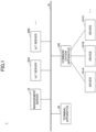
- FIG. 1 is a diagram illustrating an example of a system configuration of a communication system according to an embodiment.
- a communication system 1 includes a management server 10 connected to a communication network N, one or more Internet of Things (IoT) servers 20A, 20B, and so forth, a terminal apparatus 30, a communication apparatus 100, and the like.
- IoT Internet of Things
- the IoT server 20 when indicating any IoT server among one or more IoT servers 20A, 20B, and so forth, the IoT server is referred to as the "IoT server 20".
- the number of IoT servers 20 illustrated in FIG. 1 is an example, and may be any other number.
- the communication network N is, for example, a network such as the Internet, a local area network (LAN), a wide area network (WAN), or the like.
- the communication network N may include, for example, a communication section according to wireless communication such as a wireless LAN, a wireless WAN, or the like.
- the communication apparatus 100 is, for example, an edge (gateway device) that is communicatively connected to the plurality of devices 101A, 101B, 101C, and so forth, and collects data acquired by the plurality of devices 101A, 101B, 101 C, and so forth, and transmits the acquired data to the IoT server 20.
- the "device 101" is used to indicate any of the plurality of devices 101A, 101B, 101C, and so forth.
- the communication apparatus 100 may have a function of transmitting an instructed command to the device 101 in accordance with an instruction from the IoT server 20.
- the device 101 is a device such as an air conditioner, various sensors, etc., which acquires predetermined data and transmits the data to the communication apparatus 100.
- the communication apparatus 100 stores, in advance, connection information (hereinafter referred to as the first connection information) and firmware (hereinafter referred to as the first firmware) for connection to the management server 10. Further, the communication apparatus 100 connects to the management server 10 by using the first connection information and the first firmware the first time the power is turned on, for example, and acquires connection information (hereinafter referred to as the second connection information) and firmware (hereinafter referred to as the second firmware) for connection to the IoT server 20 that is the connection destination.
- connection information hereinafter referred to as the first connection information
- firmware hereinafter referred to as the first firmware
- the second connection information includes, for example, the URL (Uniform Resource Locator) of the IoT server that is the connection destination, and authentication information, etc., for authenticating the communication apparatus 100.
- the firmware is a program (software) incorporated into the communication apparatus 100 for controlling the communication apparatus 100.
- the second firmware includes, for example, a communication protocol, an authentication method, a data format, setting information and the like for communicating with the IoT server 20 that is the connection destination.
- the management server (first server) 10 is, for example, an information processing apparatus having a computer configuration or a system including a plurality of computers.
- the management server 10 displays, on the terminal apparatus 30, for example, a selection screen for selecting a connection destination of the communication apparatus 100 and receives a selection of a service to be used by the communication apparatus 100 or the IoT server (second server) 20.
- the management server 10 receives, from the communication apparatus 100, apparatus identification information (hereinafter referred to as communication apparatus ID) identifying the communication apparatus 100 and identifies the IoT server that is the connection destination of the communication apparatus 100 selected on the selection screen.
- the management server 10 transmits, to the communication apparatus 100, the second connection information and the second firmware for connecting to the IoT server 20 that is the connection destination of the communication apparatus 100.
- a part of or the entirety of the second connection information may be included in the second firmware.
- the terminal apparatus 30 is, for example, an information terminal such as a personal computer (PC), a tablet terminal, a smartphone or the like.
- the terminal apparatus 30 includes various terminal apparatuses such as, for example, a terminal apparatus used by a worker on a manufacturing line for manufacturing the communication apparatus 100, a terminal apparatus used by a manager or the like who manages the communication apparatus 100, or a terminal apparatus used by a builder who installs the communication apparatus 100.
- the IoT server (second server) 20 is, for example, an information processing apparatus having a computer configuration or a system including a plurality of computers.
- the IoT server 20 receives IoT data transmitted by the communication apparatus 100, performs data processing, and provides various services, for example, remote monitoring and fault diagnosis.
- the communication apparatus 100 can acquire, from the management server 10, not only the second connection information of the IoT server 20 that is the connection destination but also the second firmware for connecting to the IoT server 20 that is the connection destination. Accordingly, the communication apparatus 100 according to the present embodiment can appropriately communicate with other communication systems that are operated by various partner companies and continue to evolve daily.
- the communication apparatus 100 that communicates with the server based on connection information and firmware for connecting to the server, can appropriately communicate with other communication systems.
- the communication apparatus 100, the management server 10, the IoT server 20, and the terminal apparatus 30, etc., according to the present embodiment have, for example, a hardware configuration of a computer 200 as illustrated in FIG. 2 .
- the management server 10 and the IoT server 20, etc. are configured by a plurality of the computers 200.
- FIG. 2 is a diagram illustrating an example of a hardware configuration of a computer according to an embodiment.
- the computer 200 includes, for example, a CPU (Central Processing Unit) 201, a memory 202, a storage device 203, a communication I/F (Interface) 204, an output device 205, an input device 206, and a bus 207.
- a CPU Central Processing Unit
- the CPU 201 is a processor that performs various functions by executing predetermined programs stored in a recording medium such as, for example, the storage device 203 or the memory 202.
- the memory 202 includes, for example, a RAM (Random Access Memory), which is a volatile memory used as a work area of the CPU 201, and a ROM (Read Only Memory), which is a nonvolatile memory that stores programs for activating the computer 200.
- the storage device 203 is a large-capacity storage device for storing an OS (Operating System), a program such as an application, various kinds of data, information, etc., and is implemented by, for example, an SSD (Solid State Drive) or a HDD (Hard Disk Drive).
- the communication I/F 204 includes one or more communication interfaces, for example, a LAN, a WAN (Wide Area Network), etc., that connect the computer 200 to the communication network N to communicate with other apparatuses.
- the output device 205 includes a display apparatus that displays various display screens, or a voice output device that outputs voice messages, error sounds, etc.
- the input device 206 is, for example, an input device that receives input, such as a touch panel, a keyboard, or a pointing device.
- the output device 205 and the input device 206 may be, for example, a display input device such as a touch panel display.
- the bus 207 is connected to each of the above elements and transmits, for example, an address signal, a data signal, and various control signals.
- the hardware configuration of the device 101 may be any configuration, and the description thereof will be omitted here.
- FIG. 3 is a diagram illustrating an example of a functional configuration of a communication system according to an embodiment.
- the communication apparatus 100 includes, for example, a communication control unit 301, an acquiring unit 302, a device managing unit 303, and a storage unit 304.
- the communication control unit 301 is implemented by first firmware (hereinafter referred to as the first FW) 305 or second firmware (hereinafter referred to as the second FW) 307 executed by the CPU 201 provided in the communication apparatus 100.
- first firmware hereinafter referred to as the first FW
- second firmware hereinafter referred to as the second FW
- the communication control unit 301 communicates with the management server (first server) 10 by using the first connection information.
- the communication control unit 301 communicates with the IoT server (second server) 20 that is the connection destination by using the second connection information.
- the acquiring unit 302 is implemented by a program (the first FW 305) executed by the CPU 201, and acquires, from the management server 10, the second FW 307, second connection information 308, and the like, for connecting to the IoT server 20 that is the connection destination.
- the second connection information 308 may be included in the second FW 307.
- the acquiring unit 302 may acquire the second FW 307 from the management server 10.
- the device managing unit 303 is implemented by a program (the second FW 307) executed by the CPU 201, and transmits the IoT data collected from the plurality of devices 101 to the IoT server 20 that is the connection destination via the communication control unit 301.
- the storage unit 304 is implemented by, for example, the storage device 203 provided in the communication apparatus 100, and stores in advance the first FW 305 and the first connection information 306.
- the storage unit 304 stores the second FW 307 and the second connection information 308 acquired by the acquiring unit 302.
- the management server (first server) 10 implements a transmitting/receiving unit 311, a receiving unit 312, a first generating unit 313, an apparatus information managing unit 314, an apparatus management DB 315, and FW providing units 316A, 316B, and so forth, by executing a predetermined program on the computer 200 provided in the management server 10.
- a transmitting/receiving unit 311, a receiving unit 312, a first generating unit 313, an apparatus information managing unit 314, an apparatus management DB 315, and FW providing units 316A, 316B, and so forth by executing a predetermined program on the computer 200 provided in the management server 10.
- At least a part of the above functional configurations may be implemented by hardware.
- the transmitting/receiving unit 311 connects the management server 10 to the communication network N by using the communication I/F 204 provided in the management server 10, and executes transmission processing for transmitting data to other apparatuses and reception processing for receiving data from other apparatuses.
- the receiving unit 312 provides, to the terminal apparatus 30 or the like, a web UI (User Interface) for displaying a display screen such as a setting screen for setting the connection destination of the communication apparatus 100, and receives a setting operation, an input operation, or a selection operation on the display screen.
- the receiving unit 312 also provides a web API (Application Programming Interface) for using the function provided by the management server 10 from the IoT server 20, the terminal apparatus 30, the communication apparatus 100 or the like, and receives request information from each apparatus.
- a web UI User Interface
- the receiving unit 312 also provides a web API (Application Programming Interface) for using the function provided by the management server 10 from the IoT server 20, the terminal apparatus 30, the communication apparatus 100 or the like, and receives request information from each apparatus.
- the first generating unit 313 generates first connection information 306 for the communication apparatus 100 to connect to the management server 10 in response to a request to issue first connection information from, for example, the exclusive-use terminal apparatus 30 provided in a manufacturing line for manufacturing the communication apparatus 100.
- the first connection information 306 generated by the first generating unit 313 includes, for example, URL information of the management server 10 and authentication information for connecting to the management server 10.
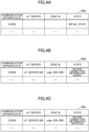
- the apparatus information managing unit 314 stores and manages apparatus information 400a to 400e of the communication apparatus 100, such as those illustrated in FIGS. 4A to 4E , in the apparatus management DB 315.
- apparatus information 400 is used.
- the apparatus information 400 includes information such as "communication apparatus ID”, “IoT server”, “edge ID”, and “state” as items.
- the "communication apparatus ID” is identification information identifying the hardware of the communication apparatus 100.
- the “IoT server” is identification information identifying the IoT server that is the connection destination of the communication apparatus 100, or information such as a name.
- the "edge ID” is identification information identifying the communication apparatus 100 functioning as an edge in the service provided by the "IoT server”.
- the "state” is information indicating the state of the communication apparatus 100.
- the apparatus information 400 may have an item of "service” instead of "Iot server".
- "Service” is information indicating a service provided by the IoT server 20.
- the apparatus information managing unit 314 stores association information 401 indicating the association relationship between "service” and "IoT server” in the apparatus management DB 315, etc., so that the identification information, name, etc., of the IoT server 20 providing the "service” can be identified.
- the apparatus management DB 315 is, for example, a database for storing the apparatus information 400 as illustrated in FIGS. 4A to 4E .
- the apparatus management DB 315 stores information of the IoT server 20 that is the connection destination, for each communication apparatus ID identifying the communication apparatus 100.
- a part of the functions of the apparatus management DB 315 may be implemented by the apparatus management DB 324 provided in the IoT servers 20A, 20B, and so forth.
- the apparatus information 400d may be managed by the apparatus management DB 315 of the management server or by the apparatus management DB 324 of the IoT server 20.
- the apparatus management DB 315 and 324 may be implemented by another computer 200 different from the management server 10 and the IoT server 20.
- the FW providing units 316A, 316B, and so forth execute processing for providing the second FW 307 and the second connection information 308 for connecting to the IoT servers 20A, 20B, and so forth.
- the FW providing unit 316A executes processing for providing the communication apparatus 100 with the second FW 307 and the second connection information 308 for connecting to the IoT server 20A.
- the FW providing unit 316B executes processing for providing the communication apparatus 100 with the second FW 307 and the second connection information 308 for connecting to the IoT server 20B.
- the "FW providing unit 316" is used. In FIG. 3 , it is assumed that the FW providing units 316B and so forth have the same functional configuration as the FW providing unit 316A.
- the FW providing unit 316 includes, for example, a FW managing unit 317, a second generating unit 318, and a storage unit 319.
- the FW managing unit 317 stores and manages the second FW 307 for connecting to the IoT server 20 corresponding to the FW providing unit 316, in the storage unit 319 or the like.
- the FW managing unit 317 of the FW providing unit 316A stores and manages the second FW 307 for connecting to the IoT server 20A, in the storage unit 319 or the like.
- the second generating unit 318 generates the second connection information 308 for connecting to the IoT server 20 corresponding to the FW providing unit 316.
- the second generating unit 318 of the FW providing unit 316A generates the second connection information 308 for connecting to the IoT server 20A.
- the FW providing unit 316 may request the IoT server 20 to generate the second connection information 308.
- the FW providing unit 316A may request the IoT server 20A to generate the second connection information 308 without having the second generating unit 318. In this case, the FW providing unit 316 serves as a bridge with the IoT server 20.
- the second connection information 308 includes, for example, the URL of the IoT server 20 that is the connection destination, an edge ID identifying the communication apparatus 100 serving as an edge in the service provided by the IoT server 20 that is the connection destination, and a device certificate (an example of authentication information).
- the storage unit 319 stores, for example, the second FW 307 managed by the FW managing unit 317 and the second connection information 308 generated by the second generating unit 318.
- the IoT server (second server) 20 implements a transmitting/receiving unit 321, an apparatus information managing unit 322, a service providing unit 323, an apparatus management DB 324, and the like by executing a predetermined program on the computer 200 provided in the IoT server 20. At least a part of the above functional configurations may be implemented by hardware.
- the transmitting/receiving unit 321 connects the IoT server 20 to the communication network N by using the communication I/F 204 provided in the IoT server 20, and executes transmission processing for transmitting data to other apparatuses and reception processing for receiving data from other apparatuses.
- the apparatus information managing unit 322 stores and manages the state of the communication apparatus 100 connected to the IoT server 20, in the apparatus management DB 324 or the like.
- the apparatus information managing unit 322 may store and manage the state of the communication apparatus 100 connected to the IoT server, in the apparatus management DB 324 provided in the management server 10.
- the apparatus information managing unit 322 may register the state of the communication apparatus 100 in the apparatus management DB 315 by using a web API provided by the receiving unit 312, or may report, to the apparatus information managing unit 314 of the management server 10, the state of the communication apparatus 100.
- the apparatus management DB 324 stores information indicating the state of the communication apparatus 100 connected to the IoT server 20, for example, the apparatus information 400d as illustrated in FIG. 4D .
- the service providing unit 323 provides services such as a remote monitoring service and a fault diagnosis service provided by the IoT server 20.
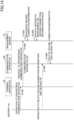
- FIG. 5 is a sequence diagram illustrating an example of processing when manufacturing the communication apparatus according to the first embodiment. This process illustrates an example of a process for storing the first FW 305, the first connection information 306, and the like in the communication apparatus 100 in a line for manufacturing the communication apparatus 100. It is assumed that the terminal apparatus 30 has already logged in to the management server 10 at the start of the processing illustrated in FIG. 5 .
- step S501 when the line worker performs the initial setting operation of the communication apparatus 100, with respect to the exclusive-use terminal apparatus 30 provided on the line, the communication system 1 executes the processing from step S502 and onward.
- step S502 the terminal apparatus 30 transmits a request for issuing the first connection information 306 to the management server 10.
- step S503 when the receiving unit 312 of the management server 10 receives the request for issuing the first connection information, the first generating unit 313 generates the first connection information for the communication apparatus 100 to connect to the management server 10.
- the first connection information includes, for example, a URL for connecting to the management server 10 and authentication information.
- the first generating unit 313 generates unique authentication information for each communication apparatus 100.
- step S504 the apparatus information managing unit 314 of the management server 10 updates the apparatus management DB 315.
- the apparatus information managing unit 314 updates the item "state" of the apparatus information 400a of the communication apparatus 100 to "initial state" as illustrated in FIG. 4A .
- the communication apparatus ID of the communication apparatus 100 may be issued by the terminal apparatus 30 or by the management server 10.
- the terminal apparatus 30 issues the communication apparatus ID
- the terminal apparatus 30 transmits, to the management server 10, a request for issuing the first connection information including the communication apparatus ID of the communication apparatus 100.
- step S505 the transmitting/receiving unit 311 of the management server 10 transmits the first connection information 306 generated by the first generating unit 313 to the terminal apparatus 30 that is the request source.
- step S506 the terminal apparatus 30 writes the first connection information 306 received from the management server 10 and the first FW 305 into the communication apparatus 100.
- step S507 the first connection information 306 and the first FW 305 are stored in the storage unit 304 of the communication apparatus 100.
- the communication apparatus 100 is shipped from the factory in this state (initial state), for example.
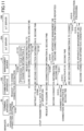
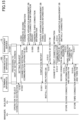
- FIG. 6 is a sequence diagram (1) illustrating an example of processing at the time of installation of the communication apparatus according to the first embodiment. This processing illustrates an example of the processing for installing, at a predetermined location, the communication apparatus 100 in which the first FW 305 and the first connection information 306 are stored in the storage unit 304 by the processing illustrated in FIG. 5 , and connecting the communication apparatus 100 to the IoT server 20.
- a system administrator who manages the communication system 1 or a manager such as a shipment administrator who manages the shipment of the communication apparatus 100 performs a display operation of the displaying setting screen with respect to the terminal apparatus 30.
- the terminal apparatus 30 is any information terminal logged in to the management server 10 and can display a display screen (web page) provided by the management server 10, by using a web browser or an application program (hereinafter referred to as an app) corresponding to the communication system 1.
- the terminal apparatus 30 illustrated in FIG. 6 may be different from the terminal apparatus 30 illustrated in FIG. 5 .
- step S602 when the terminal apparatus 30 receives the display operation for displaying the setting screen by the manager or the like, the terminal apparatus 30 transmits a display request for displaying the setting screen to the management server 10.
- steps S603 and S604 when the receiving unit 312 of the management server 10 receives the display request for displaying the setting screen, the receiving unit 312 displays, on the terminal apparatus 30, for example, a setting screen 700A as illustrated in FIG. 7A or a setting screen 700B as illustrated in FIG. 7B .
- FIG. 7A illustrates an example of the setting screen for setting the connection destination displayed by the terminal apparatus 30.
- the setting screen 700A illustrated in FIG. 7A displays a plurality of selection buttons 701 for selectably displaying the IoT servers 20A, 20B, and so forth that are candidates for the connection destination of the communication apparatus 100.
- the manager or the like selects the selection button 701A for selecting the "IoT server 20A" from among the plurality of selection buttons 701.
- FIG. 7B illustrates another example of a screen for selecting a connection destination displayed by the terminal apparatus 30.
- the setting screen 700B illustrated in FIG. 7B displays a plurality of selection buttons 702 for selectably displaying the services (for example, a remote monitoring service, a fault diagnosis service, and so on, etc.) available to the communication apparatus 100.
- the receiving unit 312 of the management server 10 may display the setting screen 700B illustrated in FIG. 7B on the terminal apparatus 30 by using the association information 401 indicating the association relationship between the IoT server 20 and the services provided by each IoT server 20 as illustrated in FIG. 4F .
- step S605 the manager or the like performs a connection destination selection operation on the setting screens illustrated in FIGS. 7A and 7B , for example.
- the manager or the like selects the selection button 701A for selecting the "IoT server 20A" from the setting screen 700A illustrated in FIG. 7A .
- step S606 when the terminal apparatus 30 receives an operation for selecting a connection destination by the manager or the like, the terminal apparatus 30 transmits, to the management server 10, a setting request including information on the selected connection destination (the IoT server 20A) and a communication apparatus ID identifying the communication apparatus 100.
- step S607 when the receiving unit 312 of the management server 10 receives a setting request, the second generating unit 318 of the FW providing unit 316A corresponding to the connection destination (the IoT server 20A) included in the setting request, generates the second connection information 308.
- the second generating unit 318 generates the second connection information 308 including a URL of the IoT server 20A, an edge ID identifying the communication apparatus 100 serving as an edge in the IoT server 20A, a device certificate (electronic certificate) of the communication apparatus 100, and the like.
- the device certificate of the communication apparatus 100 is an example of authentication information and may be other authentication information.
- the second generating unit 318 stores the generated second connection information 308 in the storage unit 319 or the like in association with the communication apparatus ID of the communication apparatus 100.
- step S608 the apparatus information managing unit 314 of the management server 10 updates the apparatus management DB 315.
- the apparatus management DB 315 stores the apparatus information 400a of the communication apparatus 100 as illustrated in FIG. 4A .
- the apparatus information managing unit 314 updates the information such as "IoT server", "edge ID", "state”, and the like of the apparatus information 400a to the apparatus information 400b as illustrated in FIG. 4B .
- the apparatus information 400b illustrated in FIG. 4B the information of the IoT server 20A that is the connection destination is stored in the item "IoT server", and the edge ID generated by the second generating unit 318 is stored in the item "edge ID”.
- the apparatus information managing unit 314 updates the item "state" of the apparatus information 400b to "second connection information issued”.
- step S609 the transmitting/receiving unit 311 of the management server 10 transmits a completion report indicating that the setting has been completed to the terminal apparatus 30 that is the request source.
- step S611 When the builder, etc., installs the communication apparatus 100 and turns on the power of the communication apparatus 100 at any timing after executing the processing in steps S601 to S609 (step S611), the communication system 1 executes the processing in step S612 and thereafter.
- step S612 the communication apparatus 100 is activated by the first FW 305 previously stored in the storage unit 304.
- step S613 the communication control unit 301 of the communication apparatus 100 is connected to the management server 10 by using the first connection information 306 previously stored in the storage unit 304. At this time, the communication control unit 301 of the communication apparatus 100 transmits a communication apparatus ID identifying the communication apparatus 100 to the management server 10.
- step S614 the apparatus information managing unit 314 of the management server 10 updates the apparatus management DB 315.
- the apparatus information managing unit 314 changes the item "state" of the apparatus information 400b illustrated in FIG. 4B to "second connection information reported" and the information is updated to the apparatus information 400c illustrated in FIG. 4C .
- step S615 the FW providing unit 316A of the management server 10 transmits, to the communication apparatus 100, the second connection information 308 corresponding to the communication apparatus ID of the communication apparatus 100 stored in the storage unit 319 and the second FW 307 for connecting to the IoT server 20A.
- the apparatus management DB 315 stores the IoT server 20 information that is the connection destination for each communication apparatus ID identifying the communication apparatus 100. Therefore, the management server 10 can determine the IoT server 20A that is the connection destination of the communication apparatus 100 and the FW providing unit 316A corresponding to the IoT server 20A based on the communication apparatus ID.
- step S616 the acquiring unit 302 of the communication apparatus 100 stores, in the storage unit 304, the second FW 307 received from the management server 10 and the second connection information 308.
- step S617 the communication apparatus 100 is reactivated by the second FW 307 stored in the storage unit 304.
- the communication apparatus 100 can connect to the IoT server 20A that is the connection destination set in the setting screen 700A or the like and communicate appropriately, by using the second connection information 308 acquired from the management server 10 and the second FW 307.
- FIG. 8 is a sequence diagram (2) illustrating an example of processing at the time of installation of the communication apparatus according to the first embodiment. This processing illustrates another example of the processing for installing, at a predetermined location, the communication apparatus 100 in which the first FW 305 and the first connection information 306 are stored in the storage unit 304 by the processing illustrated in FIG. 5 , and connecting the communication apparatus 100 to the IoT server 20.
- step S611 in FIG. 8 is the same as the process at the time of installation of the communication apparatus described in FIG. 6 , and, therefore, the description thereof will be omitted here.
- steps S801 to S809 are the same as those of steps S601 to S609 in FIG. 6 , and, therefore, the detailed description thereof will be omitted here.
- step S801 the builder or the like who installs the communication apparatus 100 performs a display operation of displaying the setting screen with respect to the terminal apparatus 30.
- step S802 when the terminal apparatus 30 receives a display operation of displaying the setting screen by the operator or the like, the terminal apparatus 30 transmits a display request to display the setting screen to the management server 10.
- steps S803 and S804 when the receiving unit 312 of the management server 10 receives the display request to display the setting screen, the receiving unit 312 causes the terminal apparatus 30 to display, for example, the setting screen 700A as illustrated in FIG. 7A or the setting screen 700B as illustrated in FIG. 7B .
- step S805 the builder or the like selects a selection button 701A for selecting the "IoT server 20A" from, for example, the setting screen 700A as illustrated in FIG. 7A .
- step S806 when the terminal apparatus 30 receives an operation for selecting a connection destination by the builder or the like, the terminal apparatus 30 transmits, to the management server 10, a setting request including information on the selected connection destination (the IoT server 20A) and the communication apparatus ID of the communication apparatus 100.
- step S807 when the receiving unit 312 of the management server 10 receives the setting request, the second generating unit 318 of the FW providing unit 316A corresponding to the connection destination (the IoT server 20A) included in the setting request, generates the second connection information 308.
- step S808 the apparatus information managing unit 314 of the management server 10 updates the apparatus management DB 315.
- step S809 the transmitting/receiving unit 311 of the management server 10 transmits a completion report indicating that the setting has been completed to the terminal apparatus 30 that is the request source.
- steps S801 to S809 in FIG. 8 can be carried out by the builder, etc., even if the manager, etc., is not present.
- FIG. 9 is a sequence diagram illustrating an example of processing at the time of data collection according to the first embodiment. This processing illustrates an example of processing executed by the communication apparatus 100 after being reactivated by the second FW 307 in step S617 of FIGS. 6 and 8 .
- step S901 when the communication apparatus 100 is reactivated by the second FW 307, the communication apparatus 100 connects to the IoT server 20A that is the connection destination, by using the second connection information 308.
- step S902 the apparatus information managing unit 322 of the IoT server 20A performs authentication processing of the communication apparatus 100 based on the second connection information 308 received from the communication apparatus 100. For example, the apparatus information managing unit 322 verifies whether the authentication information (for example, a device certificate) included in the second connection information is legitimate authentication information.
- the communication apparatus 100 has legitimate second connection information 308 issued by the management server 10, and, therefore, the apparatus information managing unit 322 permits connection by the communication apparatus 100.
- step S903 the apparatus information managing unit 322 of the IoT server 20A updates the apparatus management DB 324.
- the apparatus information managing unit 322 updates the item "state" of the apparatus information 400d of the communication apparatus 100 stored in the apparatus management DB 324 to "second connection information connected".
- the apparatus information managing unit 322 may update the apparatus information 400 stored in the apparatus management DB 315 of the management server 10 by using a web API or the like provided by the receiving unit 312 of the management server 10.
- the communication apparatus 100 is communicatively connected to the IoT server 20A, and can execute data collection processing as illustrated in steps S911 and S912, for example.
- step S911 the device managing unit 303 of the communication apparatus 100 collects data transmitted by the plurality of devices 101A, 101B, 101C, and so forth.
- step S912 the device managing unit 303 of the communication apparatus 100 transmits the collected data as IoT data to the IoT server 20A at a predetermined timing.
- the type of data collected by the device managing unit 303, the timing of transmitting IoT data, the format of IoT data and the like are all programmed in the second FW 307. Accordingly, the communication apparatus 100 can appropriately communicate with the IoT server 20A that is the connection destination.
- the communication apparatus 100 acquires the second FW 307 in addition to the second connection information 308 in accordance with the IoT server 20 that is the connection destination, and reactivates the communication apparatus 100 by the acquired second FW 307. Therefore, the communication apparatus 100 can appropriately communicate with other IoT servers even when the IoT server 20 that is the connection destination is changed to another IoT server (for example, the IoT server 20B).
- FIG. 10 is a sequence diagram (1) illustrating an example of connection destination changing processing according to the first embodiment.
- This processing illustrates an example of processing in which the communication apparatus 100 communicates with the management server 10 based on an instruction from outside such as that from the management server 10 or the IoT server 20A to reacquire the second FW 307 for connecting to another IoT server 20B.
- the second connection information 308 for connecting to the IoT server 20A is defined as “second connection information A”, and the second connection information 308 for connecting to the IoT server 20B is defined as “second connection information B”, to distinguish these from each other.
- the second FW 307 for connecting to the IoT server 20A is defined as “second FWA”, and the second FW 307 for connecting to the IoT server 20B is defined as “second FWB”, to distinguish these from each other.
- the terminal apparatus 30 is displaying a change screen for changing the connection destination of the communication apparatus 100, for example, by the same procedures as in steps S802 to S804 of FIG. 8 .
- step S1001 the manager or the like performs a change operation for changing the connection destination of the communication apparatus 100 to the IoT server 20B, on the change screen displayed by the terminal apparatus 30.
- step S1002 when the terminal apparatus 30 receives the change operation for changing the connection destination by the manager or the like, the terminal apparatus 30 transmits, to the management server 10, a change request for changing the connection destination including the information of the IoT server 20B to which the connection destination has been changed and the communication apparatus ID of the communication apparatus 100.
- step S1003 when the receiving unit 312 of the management server 10 receives the change request, the second generating unit 318 of the FW providing unit 316B corresponding to the connection destination (the IoT server 20B) included in the change request, generates the second connection information B.
- the second generating unit 318 generates the second connection information B including the URL of the IoT server 20B, the edge ID identifying the communication apparatus 100 serving as the edge in the IoT server 20B, the device certificate of the communication apparatus 100, and the like.
- the second generating unit 318 stores the generated second connection information B in the storage unit 319 of the FW providing unit 316B in association with the communication apparatus ID of the communication apparatus 100.
- the FW providing unit 316B may request the IoT server 20B to create the second connection information B as described above.
- the FW providing unit 316B stores the second connection information B generated by the IoT server 20B in the storage unit 319 or the like of the FW providing unit 316B in association with the communication apparatus ID of the communication apparatus 100.
- step S1004 the apparatus information managing unit 314 of the management server 10 updates the apparatus management DB 315.
- the item of "IoT server” is updated to "IoT server 20B”
- the item of "edge ID” is updated to the edge ID included in the second connection information B.
- the apparatus information managing unit 314 also updates the item of "state” to "second connection information issued ".
- step S1005 the FW providing unit 316A corresponding to the IoT server 20A of the management server 10 invalidates the second connection information A for the communication apparatus 100.
- step S1006 the FW providing unit 316A may add that the second connection information A is invalid in the "state" item of the apparatus information of the communication apparatus 100.
- step S1007 the FW providing unit 316B of the management server 10 instructs the communication apparatus 100 to acquire the second connection information B and the second FWB.
- step S1008 the device managing unit 303 of the communication apparatus 100 stops transmission of IoT data to the IoT server 20A.
- step S1009 the acquiring unit 302 of the communication apparatus 100 requests the management server 10 to acquire the second connection information B and the second FWB.
- step S1010 the apparatus information managing unit 314 of the management server 10 updates the item of "state" of the apparatus information of the communication apparatus 100 stored in the apparatus management DB 315 to "second connection information B reported".
- step S1011 the FW providing unit 316B of the management server 10 transmits, to the communication apparatus 100, the second connection information B corresponding to the communication apparatus ID of the communication apparatus 100 stored in the storage unit 319 and the second FWB for connecting to the IoT server 20B.
- step S1012 the acquiring unit 302 of the communication apparatus 100 overwrites the second FWB received from the management server 10 and the second connection information B in the storage unit 304.
- step S1013 the communication apparatus 100 is reactivated by the second FWB stored in the storage unit 304.
- step S1014 when the communication apparatus 100 is reactivated by the second FWB, the communication apparatus 100 connects to the IoT server 20B that is the connection destination by using the second connection information B.
- step S1015 the apparatus information managing unit 322 of the IoT server 20B performs authentication processing of the communication apparatus 100 based on the second connection information B received from the communication apparatus 100.
- the communication apparatus 100 has the legitimate second connection information B issued by the management server 10, and, therefore, the apparatus information managing unit 322 permits connection by the communication apparatus 100.
- step S1016 the apparatus information managing unit 322 of the IoT server 20B updates the item of "state" of the apparatus information of the communication apparatus 100 stored in the apparatus management DB 315 to "second connection information B connected".
- the communication apparatus 100 is communicatively connected to the IoT server 20B, and various processes can be executed.
- FIG. 11 is a sequence diagram (2) illustrating an example of connection destination changing processing according to the first embodiment.
- This processing illustrates another example of processing in which the communication apparatus 100 communicates with the management server 10 based on an instruction from outside such as that from the management server 10 or the IoT server 20A to reacquire the second FW 307 for connecting to another IoT server 20B.
- steps S1001, S1002, and S1008 to S1016 are similar to the processing in steps S1001, S1002, and S1008 to S1016 in FIG. 10 , so the differences from the processing in FIG. 10 will be described here.
- step S1101 the management server 10 executes the processing of issuing the second connection information B as illustrated in steps S1003 to S1006 in FIG. 10 .
- step S1102 the FW providing unit 316B of the management server 10 requests the IoT server 20A to which the communication apparatus 100 is connected, to instruct the communication apparatus 100 to acquire the second connection information B and the second FWB.
- step S1103 the transmitting/receiving unit 321 of the IoT server 20A instructs the communication apparatus 100 to acquire the second connection information B and the second FWB.
- the FW providing unit 316B of the management server 10 may instruct the communication apparatus 100 to acquire the second connection information B and the second FWB by using the IoT server 20A to which the communication apparatus 100 is connected.
- FIG. 12 is a sequence diagram (3) illustrating an example of connection destination changing processing according to the first embodiment.
- This processing illustrates another example of processing when a manager or the like changes the IoT server 20 that is the connection destination to be connected to the installed communication apparatus 100.
- the processing in steps S1001, S1002, S1014, and S1015 is similar to the processing in steps S1001, S1002, S1014, and S1015 in FIG. 10 , and, therefore, the difference from the processing in FIG. 10 will be mainly described here.
- step S1201 the management server 10 executes the processing of issuing the second connection information B as illustrated in steps S1003 to S1006 in FIG. 10 .
- step S1202 the FW providing unit 316B of the management server 10 requests the IoT server 20A to which the communication apparatus 100 is connected, to instruct the communication apparatus 100 to perform initialization.
- step S1203 the transmitting/receiving unit 321 of the IoT server 20A instructs the communication apparatus 100 to perform initialization.
- step S1204 the communication apparatus 100 performs initialization. For example, the communication apparatus 100 deletes the second FWA and the second connection information A stored in the storage unit 304 and is reactivated by the first FW 305.
- step S1205 the communication apparatus 100 and the management server 10 execute second connection information acquiring processing, for example, as illustrated in steps S613 to S617 of FIG. 6 , and is reactivated by the second FWB.
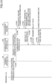
- FIG. 13 is a sequence diagram (1) illustrating an example of processing at the time of discontinuance according to the first embodiment. This processing illustrates an example of a processing when discontinuing the installed communication apparatus 100.
- the terminal apparatus 30 is displaying a setting screen for receiving a discontinuance operation of discontinuing the communication apparatus 100, for example, by the same procedures as in steps S802 to S804 of FIG. 8 .
- step S1301 the manager or the like performs a discontinuance operation of discontinuing the communication apparatus 100 on the setting screen displayed by the terminal apparatus 30.
- step S1302 when the terminal apparatus 30 receives the discontinuance operation of discontinuing the communication apparatus 100 by the manager or the like, the terminal apparatus 30 transmits, to the management server 10, a discontinuance request to discontinue the communication apparatus including the communication apparatus ID of the communication apparatus 100 to be discontinued.
- the apparatus information managing unit 314 of the management server 10 invalidates the second connection information 308 corresponding to the communication apparatus 100.
- step S1304 the apparatus information managing unit 314 of the management server 10 sets the "state" item of the apparatus information of the communication apparatus 100 stored in the apparatus management DB 315 to "second connection information invalid" (or “discontinued”).
- step S1305 the apparatus information managing unit 314 of the management server 10 transmits a discontinuance instruction to the communication apparatus 100.
- step S1306 the device managing unit 303 of the communication apparatus 100 stops transmission of IoT data.
- step S1307 the communication apparatus 100 deletes the second FW 307 and the second connection information 308 stored in the storage unit 304.
- the manager or the like can execute the discontinuance processing of discontinuing the communication apparatus 100 by remote operation.
- FIG. 14 is a sequence diagram (2) illustrating an example of processing at the time of discontinuance according to the first embodiment. This processing illustrates another example of a processing when discontinuing the installed communication apparatus 100.
- the terminal apparatus 30 is displaying a setting screen for receiving a discontinuance operation of discontinuing the communication apparatus 100, for example, in the same procedures as in steps S802 to S804 of FIG. 8 .
- step S1401 the builder, etc., performs the discontinuance operation for discontinuing the communication apparatus 100 on the setting screen displayed by the terminal apparatus 30.
- step S1402 when the terminal apparatus 30 receives the discontinuance operation of discontinuing the communication apparatus 100 by the operator or the like, the terminal apparatus 30 transmits, to the management server 10, a discontinuance request of discontinuing the communication apparatus including the communication apparatus ID of the communication apparatus 100 to be discontinued.
- the apparatus information managing unit 314 of the management server 10 invalidates the second connection information 308 corresponding to the communication apparatus 100.
- step S1404 the apparatus information managing unit 314 of the management server 10 sets the "state" item of the apparatus information of the communication apparatus 100 stored in the apparatus management DB 315 to "second connection information invalid" (or “discontinued”).
- step S1405 the builder, etc., performs a deletion operation of deleting the second connection information 308 and the second FW 307 with respect to the communication apparatus 100.
- step S1405 the communication apparatus 100 deletes the second FW 307 and the second connection information 308 stored in the storage unit 304.
- discontinuance processing of discontinuing the communication apparatus 100 can be carried out by the builder or the like at the place where the communication apparatus 100 is installed.
- the number of the IoT servers 20 to which the communication apparatus 100 transmits IoT data is one has been described, but the number of IoT servers to which the communication apparatus 100 transmits IoT data may be a plurality.
- the communication apparatus 100 transmits IoT data to two IoT servers 20.
- the system configuration, hardware configuration, and functional configuration of the communication system 1 according to the second embodiment may be the same as that of the first embodiment.
- FIG. 15 is a sequence diagram illustrating an example of processing at the time of installation of the communication apparatus according to the second embodiment.
- This processing illustrates an example of processing for making a setting to install, at a predetermined location, the communication apparatus 100, in which the first FW 305 and the first connection information 306 are stored in the storage unit 304 by the processing illustrated in FIG. 5 , to be connected to the IoT server 20A and the IoT server 20B.
- step S1500 the communication system 1 executes the display processing of the setting screen described in steps S601 to S604 of FIG. 6 , and displays, for example, the setting screen 700A illustrated in FIG. 7A on the terminal apparatus 30.
- step S1501 the manager or the like performs the selection operation of selecting the connection destination on, for example, the setting screen 700A illustrated in FIG. 7A .
- the manager or the like selects the selection button 701A for selecting the "IoT server 20A” and the selection button 701B for selecting the "IoT server 20B" on the setting screen 700A, as described below.
- step S1502 when the terminal apparatus 30 receives the connection destination selection operation by the manager or the like, the terminal apparatus 30 transmits, to the management server 10, a setting request including the information of the selected connection destination (the IoT server 20A and the IoT server 20B) and the communication apparatus ID identifying the communication apparatus 100.
- step S1503 when the receiving unit 312 of the management server 10 receives the setting request, the second generating unit 318 of the FW providing unit 316A corresponding to the IoT server 20A generates the second connection information in accordance with the setting request.
- the second generating unit 318 of the FW providing unit 316A generates the second connection information including the URL of the IoT server 20A, the edge ID identifying the communication apparatus 100 serving as the edge in the IoT server 20A, and the authentication information of the communication apparatus 100.
- the second generating unit 318 of the FW providing unit 316A stores the generated second connection information in the storage unit 319 or the like in association with the communication apparatus ID of the communication apparatus 100.
- step S1504 the apparatus information managing unit 314 of the management server 10 updates the apparatus management DB 315.
- the apparatus information managing unit 314 stores the information of the IoT server 20A in the item "IoT server" of the apparatus information 400a of the communication apparatus 100, the generated edge ID in the item "edge ID”, and "second connection information issued” indicating the state in the item "state” as illustrated in FIG. 4A .
- the second generating unit 318 of the FW providing unit 316B corresponding to the IoT server 20B generates the third connection information according to the setting information.
- the second generating unit 318 of the FW providing unit 316B generates the third connection information including the URL of the IoT server 20B, the edge ID identifying the communication apparatus 100 serving as the edge in the IoT server 20B, the authentication information of the communication apparatus 100, and the like.
- the second generating unit 318 of the FW providing unit 316B stores the generated third connection information in the storage unit 319 and the like in association with the communication apparatus ID of the communication apparatus 100.
- step S1506 the apparatus information managing unit 314 of the management server 10 updates the apparatus management DB 315.
- the apparatus information managing unit 314 updates the items of "IoT server", "edge ID”, and "state” in the apparatus information 400a of the communication apparatus 100 as illustrated in FIG. 4B .
- the apparatus information managing unit 314 adds the information of the IoT server 20B that is the connection destination to the item "IoT server”, adds the edge ID generated by the second generating unit 318 to the item "edge ID”, and adds "third connection information issued” indicating the state to the item "state”.
- step S1507 the transmitting/receiving unit 311 of the management server 10 transmits a completion report indicating that the setting has been completed to the terminal apparatus 30 that is the request source.
- step S1511 When the builder, etc., installs the communication apparatus 100 and turns on the power of the communication apparatus 100 at any timing after executing the processing in steps S1501 to S1507 (step S1511), the communication system 1 executes the processing in step S1512 and thereafter.
- step S1512 the communication apparatus 100 is activated by the first FW 305 previously stored in the storage unit 304.
- step S1513 the communication control unit 301 of the communication apparatus 100 connects to the management server 10 by using the first connection information 306 previously stored in the storage unit 304. At this time, the communication control unit 301 of the communication apparatus 100 transmits a communication apparatus ID identifying the communication apparatus 100 to the management server 10.
- step S1514 the apparatus information managing unit 314 of the management server 10 updates the apparatus management DB 315.
- the apparatus information managing unit 314 updates the item "state" corresponding to the apparatus ID of the communication apparatus to "initially connected" in the apparatus information 400 stored in the apparatus management DB 315.
- step S1515 the FW providing unit 316A of the management server 10 transmits, to the communication apparatus 100, the second connection information 308 corresponding to the communication apparatus ID of the communication apparatus 100 stored in the storage unit 319 and the second FW 307 for connecting to the IoT server 20A.
- step S1516 the acquiring unit 302 of the communication apparatus 100 stores, in the storage unit 304, the second FW 307 and the second connection information 308 received from the management server 10.
- step S1517 the FW providing unit 316B of the management server 10 transmits, to the communication apparatus 100, the third connection information corresponding to the communication apparatus ID of the communication apparatus 100 and the third FW (firmware) for connecting to the IoT server 20B stored in the storage unit 319.
- step S1518 the acquiring unit 302 of the communication apparatus 100 stores, in the storage unit 304, the third FW and the third connection information received from the management server 10.
- the acquiring unit 302 may overwrite the first FW 305 stored in the storage unit 304 with the third FW received from the management server 10.
- the acquiring unit 302 may overwrite the first FW 305 stored in the storage unit 304 with the third FW received from the management server 10.
- FIG. 16 is a sequence diagram illustrating an example of processing when collecting data according to the second embodiment. This processing illustrates an example of processing when collecting data executed by the communication system 1 after executing the processing of installing the communication apparatus described in FIG. 15 .
- step S1601 the communication apparatus 100 connects to the IoT server 20A that is the connection destination by using, for example, the second connection information 308 and the second FW 307 stored in the storage unit 304.
- step S1602 the apparatus information managing unit 322 of the IoT server 20A performs authentication processing of authenticating the communication apparatus 100 based on the second connection information 308 received from the communication apparatus 100. For example, the apparatus information managing unit 322 verifies whether the authentication information (for example, a device certificate) included in the second connection information is legitimate authentication information.
- the communication apparatus 100 has legitimate second connection information 308 issued by the management server 10, and, therefore, the apparatus information managing unit 322 permits connection by the communication apparatus 100.
- the apparatus information managing unit 322 of the IoT server 20A updates the apparatus management DB 324.
- the apparatus information managing unit 322 updates the "state" of the communication apparatus 100 stored in the apparatus management DB 324 of the IoT server 20A to "second connection information connected".
- the apparatus information managing unit 322 may update the apparatus information 400 stored in the apparatus management DB 315 of the management server 10 by using a web API or the like provided by the receiving unit 312 of the management server 10.
- the communication apparatus 100 can transmit, to the IoT server 20A, IoT data including data received from the devices 101A, 101B, 101C, and so forth in steps S1604 and S1605.
- step S1611 the communication apparatus 100 connects to the IoT server 20B that is the connection destination by using, for example, the third connection information and the third FW stored in the storage unit 304.
- step S1612 the apparatus information managing unit 322 of the IoT server 20B performs authentication processing of authenticating the communication apparatus 100 based on the third connection information received from the communication apparatus 100. For example, the apparatus information managing unit 322 verifies whether the authentication information included in the third connection information is legitimate authentication information.
- the communication apparatus 100 has legitimate third connection information issued by the management server 10, and, therefore, the apparatus information managing unit 322 permits connection by the communication apparatus 100.
- the apparatus information managing unit 322 of the IoT server 20B updates the apparatus management DB 324.
- the apparatus information managing unit 322 updates the "state" of the communication apparatus 100 stored in the apparatus management DB 324 of the IoT server 20B to "third connection information connected".
- the apparatus information managing unit 322 may update the apparatus information 400 stored in the apparatus management DB 315 of the management server 10 by using a web API or the like provided by the receiving unit 312 of the management server 10.
- the communication apparatus 100 can transmit, to the IoT server 20A, IoT data including data received from the devices 101A, 101B, 101C, and so forth in step S1614.
- the communication apparatus 100 can transmit IoT data to the IoT server 20A and the IoT server 20B by alternately repeating the execution of the first connection processing illustrated in steps S1601 to S1603 and the processing of steps S1611 to S1613.
- the communication system 1 may use the second FW and the third FW as common firmware, and manage, by the connection information, information such as the type of data collected by the device managing unit 303, the timing of transmitting IoT data, and the format of IoT data.
- the second generating unit 318 of the FW providing unit 316A may generate the second connection information including the type of data to be collected, the timing of transmitting data, the format, etc., in addition to the URL, edge ID, and authentication information for the IoT server A.
- the second generating unit 318 of the FW providing unit 316B may generate the third connection information including the type of data to be collected, the timing of transmitting data, the format, etc., in addition to the URL, edge ID, and authentication information for the IoT server B.
- the communication apparatus 100 can connect to the IoT server 20A by using the common firmware and the second connection information in step S1601, and transmit IoT data to the IoT server 20A in accordance with the second connection information in step S1605.
- the communication apparatus 100 can connect to the IoT server 20B by using the common firmware and the third connection information in step S1611, and transmit IoT data to the IoT server 20B in accordance with the third connection information in step S1614.
- the communication apparatus 100 can transmit IoT data collected from the devices 101A, 101B, 101C, and so on, etc., to the plurality of IoT servers 20.
- the communication apparatus communicating with the server based on connection information and firmware for connecting to the server can appropriately communicate with various other servers.
Landscapes
- Engineering & Computer Science (AREA)
- Computer Networks & Wireless Communication (AREA)
- Signal Processing (AREA)
- Computing Systems (AREA)
- Computer Hardware Design (AREA)
- Computer Security & Cryptography (AREA)
- General Engineering & Computer Science (AREA)
- Health & Medical Sciences (AREA)
- General Health & Medical Sciences (AREA)
- Medical Informatics (AREA)
- Computer And Data Communications (AREA)
Abstract
communicate with a first server based on first connection information and first firmware for connecting to the first server, and
acquire, from the first server, second firmware for connecting to a second server different from the first server.
Description
- The present disclosure relates to a communication apparatus, a server, a communication system, and a communication method.
- There is a gateway device (hereinafter referred to as a communication apparatus) that collects data from an electronic device and transmits, via a communication network, the collected data to an Internet of Things (IoT) server that provides various services such as monitoring of the electronic device.
- Further, in order to enable such a communication apparatus to connect to an appropriate connection destination, there is known a technique for transmitting first identification information to a server and acquiring the information of a second connection destination corresponding to the first identification information (see, e.g., Patent Document 1).
- Patent document 1:
Japanese Patent No. 6813110 - The communication apparatus as described in
Patent Document 1 operates on firmware that is premised on being connected to the server of the own company (cloud service, etc.), and, therefore, it has been difficult to form an alliance with a partner company or the like and connect to another company's server, for example. For example, as described inPatent Document 1, by only acquiring information on the second connection destination, it is sometimes impossible to properly communicate with other communication systems that are operated by various partner companies and that continue to evolve on a daily basis. - The present disclosure makes it possible to appropriately communicate with various kinds of other servers by a communication apparatus communicating with a server, based on connection information and firmware for connecting to the server.
- A communication apparatus according to a first aspect of the present disclosure is configured to
- communicate with a first server based on first connection information and first firmware for connecting to the first server, and
- acquire, from the first server, second firmware for connecting to a second server different from the first server.
- According to the first aspect of the present disclosure, the communication apparatus communicating with the server based on the connection information and the firmware for connecting to the server, can appropriately communicate with various other servers.
- A second aspect of the present disclosure is the communication apparatus according to the first aspect, wherein
- the communication apparatus acquires, from the first server, second connection information for connecting to the second server, and
- the second connection information includes authentication information for connecting to the second server.
- A third aspect of the present disclosure is the communication apparatus according to the second aspect, wherein the communication apparatus communicates with the second server based on the second connection information and the second firmware.
- A fourth aspect of the present disclosure is the communication apparatus according to any one of the first to third aspects, wherein when changing the second server to which the communication apparatus is to be connected, the communication apparatus communicates with the first server based on an instruction from outside, to reacquire firmware for connecting to a different second server that is different from the second server.
- A fifth aspect of the present disclosure is the communication apparatus according to any one of the first to fourth aspects, wherein the first connection information and the first firmware are set when the communication apparatus is manufactured.
- A server according to a sixth aspect of the present disclosure is a first server and is configured to
- receive a selection of a service to be used by a communication apparatus or a second server,
- receive, from the communication apparatus, first connection information including apparatus identification information identifying the communication apparatus, and
- transmit, to the communication apparatus, second firmware for connecting to the second server providing the service to be used by the communication apparatus.
- According to the second aspect of the present disclosure, the server can appropriately provide the communication apparatus with second firmware for connecting to a second server that is the connection destination.
- A seventh aspect of the present disclosure is the server according to the sixth aspect, wherein
the first server - stores second connection information and the second firmware for connecting to the second server, and
- transmits, to the communication apparatus, the second connection information and the second firmware for connecting to the second server providing the service to be used by the communication apparatus.
- An eighth aspect of the present disclosure is the server according to the seventh aspect, wherein
- the second connection information includes authentication information for connecting to the second server, and
- the first server generates the authentication information for connecting to the second server.
- A ninth aspect of the present disclosure is the server according to any one of the sixth to eighth aspects, wherein
the first server - stores information of the second server to which the communication apparatus is to be connected, for each piece of the apparatus identification information identifying the communication apparatus, and
- determines the second server to which the communication apparatus is to be connected, based on the apparatus identification information.
- A tenth aspect of the present disclosure is the server according to any one of the sixth to eighth aspects, wherein
the first server - stores the service to be used by the communication apparatus, for each piece of the apparatus identification information identifying the communication apparatus, and
- determines the second server to which the communication apparatus is to be connected, according to the service.
- A communication system according to an eleventh aspect of the present disclosure includes:
- a first server; and
- a communication apparatus, wherein
- the first server is configured to
- receive a selection of a service to be used by the communication apparatus,
- receive, from the communication apparatus, first connection information including apparatus identification information identifying the communication apparatus, and
- transmit, to the communication apparatus, second firmware for connecting to a second server providing the service to be used by the communication apparatus, and wherein
- the communication apparatus is configured to
- communicate with the first server based on the first connection information and first firmware for connecting to the first server, and
- acquire, from the first server, the second firmware for connecting to the second server different from the first server.
- A communication method according to a twelfth aspect of the present disclosure is in a communication system including a first server and a communication apparatus, the communication method including:
- receiving, by the first server, a selection of a service to be used by the communication apparatus;
- communicating, by the communication apparatus with the first server, based on first connection information and first firmware for connecting to the first server;
- receiving, by the first server from the communication apparatus, the first connection information including apparatus identification information identifying the communication apparatus;
- transmitting, by the first server to the communication apparatus, second firmware for connecting to a second server providing the service to be used by the communication apparatus; and
- acquiring, by the communication apparatus from the first server, the second firmware for connecting to the second server different from the first server.
-
- [
FIG. 1] FIG. 1 is a diagram illustrating an example of a system configuration of a communication system according to an embodiment. - [
FIG. 2] FIG. 2 is a diagram illustrating an example of a hardware configuration of a computer according to an embodiment. - [
FIG. 3] FIG. 3 is a diagram illustrating an example of a functional configuration of a communication system according to an embodiment. - [
FIG. 4A] FIG. 4A is a diagram (1) illustrating an example of apparatus information managed by an apparatus management DB according to an embodiment. - [
FIG. 4B] FIG. 4B is a diagram (2) illustrating an example of apparatus information managed by an apparatus management DB according to an embodiment. - [
FIG. 4C] FIG. 4C is a diagram (3) illustrating an example of apparatus information managed by an apparatus management DB according to an embodiment. - [
FIG. 4D] FIG. 4D is a diagram (4) illustrating an example of apparatus information managed by an apparatus management DB according to an embodiment. - [
FIG. 4E] FIG. 4E is a diagram (5) illustrating an example of apparatus information managed by an apparatus management DB according to an embodiment. - [
FIG. 4F] FIG. 4F is a diagram (6) illustrating an example of apparatus information managed by an apparatus management DB according to an embodiment. - [
FIG. 5] FIG. 5 is a sequence diagram illustrating an example of processing when manufacturing of a communication apparatus according to a first embodiment. - [
FIG. 6] FIG. 6 is a sequence diagram (1) illustrating an example of processing when installing a communication apparatus according to the first embodiment. - [
FIG. 7A] FIG. 7A is a diagram (1) illustrating an example of a setting screen according to the first embodiment. - [
FIG. 7B] FIG. 7B is a diagram (2) illustrating an example of a setting screen according to the first embodiment. - [
FIG. 8] FIG. 8 is a sequence diagram (2) illustrating an example of processing when installing a communication apparatus according to the first embodiment. - [
FIG. 9] FIG. 9 is a sequence diagram illustrating an example of processing when collecting data according to the first embodiment. - [
FIG. 10] FIG. 10 is a sequence diagram (1) illustrating an example of processing for changing the connection destination according to the first embodiment. - [
FIG. 11] FIG. 11 is a sequence diagram (2) illustrating an example of processing for changing the connection destination according to the first embodiment. - [
FIG. 12] FIG. 12 is a sequence diagram (3) illustrating an example of processing for changing the connection destination according to the first embodiment. - [
FIG. 13] FIG. 13 is a sequence diagram (1) illustrating an example of processing at the time of discontinuance according to the first embodiment. - [
FIG. 14] FIG. 14 is a sequence diagram (2) illustrating an example of processing at the time of discontinuance according to the first embodiment. - [
FIG. 15] FIG. 15 is a sequence diagram illustrating an example of processing when installing the communication apparatus according to a second embodiment. - [
FIG. 16] FIG. 16 is a sequence diagram illustrating an example of processing at the time of data collection according to the second embodiment. - Hereinafter, each embodiment will be described with reference to the attached drawings. In the present specification and the drawings, elements having substantially the same functional configuration will be denoted by the same reference numerals to omit duplicate descriptions.
-
FIG. 1 is a diagram illustrating an example of a system configuration of a communication system according to an embodiment. Acommunication system 1 includes amanagement server 10 connected to a communication network N, one or more Internet of Things (IoT)servers terminal apparatus 30, acommunication apparatus 100, and the like. In the following description, when indicating any IoT server among one or moreIoT servers FIG. 1 is an example, and may be any other number. - The communication network N is, for example, a network such as the Internet, a local area network (LAN), a wide area network (WAN), or the like. The communication network N may include, for example, a communication section according to wireless communication such as a wireless LAN, a wireless WAN, or the like.
- The
communication apparatus 100 is, for example, an edge (gateway device) that is communicatively connected to the plurality ofdevices devices devices communication apparatus 100 may have a function of transmitting an instructed command to the device 101 in accordance with an instruction from the IoT server 20. The device 101 is a device such as an air conditioner, various sensors, etc., which acquires predetermined data and transmits the data to thecommunication apparatus 100. - The
communication apparatus 100 according to the present embodiment stores, in advance, connection information (hereinafter referred to as the first connection information) and firmware (hereinafter referred to as the first firmware) for connection to themanagement server 10. Further, thecommunication apparatus 100 connects to themanagement server 10 by using the first connection information and the first firmware the first time the power is turned on, for example, and acquires connection information (hereinafter referred to as the second connection information) and firmware (hereinafter referred to as the second firmware) for connection to the IoT server 20 that is the connection destination. - The second connection information includes, for example, the URL (Uniform Resource Locator) of the IoT server that is the connection destination, and authentication information, etc., for authenticating the
communication apparatus 100. The firmware is a program (software) incorporated into thecommunication apparatus 100 for controlling thecommunication apparatus 100. The second firmware includes, for example, a communication protocol, an authentication method, a data format, setting information and the like for communicating with the IoT server 20 that is the connection destination. - The management server (first server) 10 is, for example, an information processing apparatus having a computer configuration or a system including a plurality of computers. The
management server 10 displays, on theterminal apparatus 30, for example, a selection screen for selecting a connection destination of thecommunication apparatus 100 and receives a selection of a service to be used by thecommunication apparatus 100 or the IoT server (second server) 20. When thecommunication apparatus 100 connects to themanagement server 10, themanagement server 10 receives, from thecommunication apparatus 100, apparatus identification information (hereinafter referred to as communication apparatus ID) identifying thecommunication apparatus 100 and identifies the IoT server that is the connection destination of thecommunication apparatus 100 selected on the selection screen. Furthermore, themanagement server 10 transmits, to thecommunication apparatus 100, the second connection information and the second firmware for connecting to the IoT server 20 that is the connection destination of thecommunication apparatus 100. A part of or the entirety of the second connection information may be included in the second firmware. - The
terminal apparatus 30 is, for example, an information terminal such as a personal computer (PC), a tablet terminal, a smartphone or the like. Theterminal apparatus 30 includes various terminal apparatuses such as, for example, a terminal apparatus used by a worker on a manufacturing line for manufacturing thecommunication apparatus 100, a terminal apparatus used by a manager or the like who manages thecommunication apparatus 100, or a terminal apparatus used by a builder who installs thecommunication apparatus 100. - The IoT server (second server) 20 is, for example, an information processing apparatus having a computer configuration or a system including a plurality of computers. The IoT server 20 receives IoT data transmitted by the
communication apparatus 100, performs data processing, and provides various services, for example, remote monitoring and fault diagnosis. - With the above configuration, the
communication apparatus 100 according to the present embodiment can acquire, from themanagement server 10, not only the second connection information of the IoT server 20 that is the connection destination but also the second firmware for connecting to the IoT server 20 that is the connection destination. Accordingly, thecommunication apparatus 100 according to the present embodiment can appropriately communicate with other communication systems that are operated by various partner companies and continue to evolve daily. - According to the present embodiment, the
communication apparatus 100 that communicates with the server based on connection information and firmware for connecting to the server, can appropriately communicate with other communication systems. - The
communication apparatus 100, themanagement server 10, the IoT server 20, and theterminal apparatus 30, etc., according to the present embodiment have, for example, a hardware configuration of acomputer 200 as illustrated inFIG. 2 . Alternatively, themanagement server 10 and the IoT server 20, etc., are configured by a plurality of thecomputers 200. -
FIG. 2 is a diagram illustrating an example of a hardware configuration of a computer according to an embodiment. Thecomputer 200 includes, for example, a CPU (Central Processing Unit) 201, amemory 202, astorage device 203, a communication I/F (Interface) 204, anoutput device 205, aninput device 206, and abus 207. - The
CPU 201 is a processor that performs various functions by executing predetermined programs stored in a recording medium such as, for example, thestorage device 203 or thememory 202. Thememory 202 includes, for example, a RAM (Random Access Memory), which is a volatile memory used as a work area of theCPU 201, and a ROM (Read Only Memory), which is a nonvolatile memory that stores programs for activating thecomputer 200. Thestorage device 203 is a large-capacity storage device for storing an OS (Operating System), a program such as an application, various kinds of data, information, etc., and is implemented by, for example, an SSD (Solid State Drive) or a HDD (Hard Disk Drive). - The communication I/
F 204 includes one or more communication interfaces, for example, a LAN, a WAN (Wide Area Network), etc., that connect thecomputer 200 to the communication network N to communicate with other apparatuses. Theoutput device 205 includes a display apparatus that displays various display screens, or a voice output device that outputs voice messages, error sounds, etc. Theinput device 206 is, for example, an input device that receives input, such as a touch panel, a keyboard, or a pointing device. Theoutput device 205 and theinput device 206 may be, for example, a display input device such as a touch panel display. Thebus 207 is connected to each of the above elements and transmits, for example, an address signal, a data signal, and various control signals. - In the present embodiment, the hardware configuration of the device 101 may be any configuration, and the description thereof will be omitted here.
-
FIG. 3 is a diagram illustrating an example of a functional configuration of a communication system according to an embodiment. - The
communication apparatus 100 includes, for example, acommunication control unit 301, an acquiringunit 302, adevice managing unit 303, and astorage unit 304. - The
communication control unit 301 is implemented by first firmware (hereinafter referred to as the first FW) 305 or second firmware (hereinafter referred to as the second FW) 307 executed by theCPU 201 provided in thecommunication apparatus 100. For example, when theCPU 201 executes thefirst FW 305, thecommunication control unit 301 communicates with the management server (first server) 10 by using the first connection information. On the other hand, when theCPU 201 executes thesecond FW 307, thecommunication control unit 301 communicates with the IoT server (second server) 20 that is the connection destination by using the second connection information. - The acquiring
unit 302 is implemented by a program (the first FW 305) executed by theCPU 201, and acquires, from themanagement server 10, thesecond FW 307,second connection information 308, and the like, for connecting to the IoT server 20 that is the connection destination. Note that thesecond connection information 308 may be included in thesecond FW 307. In this case, the acquiringunit 302 may acquire thesecond FW 307 from themanagement server 10. - The
device managing unit 303 is implemented by a program (the second FW 307) executed by theCPU 201, and transmits the IoT data collected from the plurality of devices 101 to the IoT server 20 that is the connection destination via thecommunication control unit 301. - The
storage unit 304 is implemented by, for example, thestorage device 203 provided in thecommunication apparatus 100, and stores in advance thefirst FW 305 and thefirst connection information 306. Thestorage unit 304 stores thesecond FW 307 and thesecond connection information 308 acquired by the acquiringunit 302. - The management server (first server) 10 implements a transmitting/receiving
unit 311, a receivingunit 312, afirst generating unit 313, an apparatusinformation managing unit 314, anapparatus management DB 315, andFW providing units computer 200 provided in themanagement server 10. At least a part of the above functional configurations may be implemented by hardware. - The transmitting/receiving
unit 311 connects themanagement server 10 to the communication network N by using the communication I/F 204 provided in themanagement server 10, and executes transmission processing for transmitting data to other apparatuses and reception processing for receiving data from other apparatuses. - For example, the receiving
unit 312 provides, to theterminal apparatus 30 or the like, a web UI (User Interface) for displaying a display screen such as a setting screen for setting the connection destination of thecommunication apparatus 100, and receives a setting operation, an input operation, or a selection operation on the display screen. The receivingunit 312 also provides a web API (Application Programming Interface) for using the function provided by themanagement server 10 from the IoT server 20, theterminal apparatus 30, thecommunication apparatus 100 or the like, and receives request information from each apparatus. - The
first generating unit 313 generatesfirst connection information 306 for thecommunication apparatus 100 to connect to themanagement server 10 in response to a request to issue first connection information from, for example, the exclusive-use terminal apparatus 30 provided in a manufacturing line for manufacturing thecommunication apparatus 100. Thefirst connection information 306 generated by thefirst generating unit 313 includes, for example, URL information of themanagement server 10 and authentication information for connecting to themanagement server 10. - The apparatus
information managing unit 314 stores and managesapparatus information 400a to 400e of thecommunication apparatus 100, such as those illustrated inFIGS. 4A to 4E , in theapparatus management DB 315. In the following description, when referring to any apparatus information among theapparatus information 400a to 400e, "apparatus information 400" is used. - In the examples of
FIGS. 4A to 4D , the apparatus information 400 includes information such as "communication apparatus ID", "IoT server", "edge ID", and "state" as items. The "communication apparatus ID" is identification information identifying the hardware of thecommunication apparatus 100. The "IoT server" is identification information identifying the IoT server that is the connection destination of thecommunication apparatus 100, or information such as a name. The "edge ID" is identification information identifying thecommunication apparatus 100 functioning as an edge in the service provided by the "IoT server". The "state" is information indicating the state of thecommunication apparatus 100. - As illustrated in
FIG. 4E , the apparatus information 400 may have an item of "service" instead of "Iot server". "Service" is information indicating a service provided by the IoT server 20. In this case, as illustrated inFIG. 4F , the apparatusinformation managing unit 314stores association information 401 indicating the association relationship between "service" and "IoT server" in theapparatus management DB 315, etc., so that the identification information, name, etc., of the IoT server 20 providing the "service" can be identified. - The
apparatus management DB 315 is, for example, a database for storing the apparatus information 400 as illustrated inFIGS. 4A to 4E . Theapparatus management DB 315 stores information of the IoT server 20 that is the connection destination, for each communication apparatus ID identifying thecommunication apparatus 100. A part of the functions of theapparatus management DB 315 may be implemented by theapparatus management DB 324 provided in theIoT servers apparatus information 400a to 400e illustrated inFIGS. 4A to 4E , theapparatus information 400d may be managed by theapparatus management DB 315 of the management server or by theapparatus management DB 324 of the IoT server 20. Theapparatus management DB computer 200 different from themanagement server 10 and the IoT server 20. - The
FW providing units second FW 307 and thesecond connection information 308 for connecting to theIoT servers FW providing unit 316A executes processing for providing thecommunication apparatus 100 with thesecond FW 307 and thesecond connection information 308 for connecting to theIoT server 20A. Similarly, theFW providing unit 316B executes processing for providing thecommunication apparatus 100 with thesecond FW 307 and thesecond connection information 308 for connecting to theIoT server 20B. In the following description, when referring to any FW providing unit among theFW providing units FIG. 3 , it is assumed that theFW providing units 316B and so forth have the same functional configuration as theFW providing unit 316A. - The FW providing unit 316 includes, for example, a
FW managing unit 317, asecond generating unit 318, and astorage unit 319. - The
FW managing unit 317 stores and manages thesecond FW 307 for connecting to the IoT server 20 corresponding to the FW providing unit 316, in thestorage unit 319 or the like. For example, theFW managing unit 317 of theFW providing unit 316A stores and manages thesecond FW 307 for connecting to theIoT server 20A, in thestorage unit 319 or the like. - The
second generating unit 318 generates thesecond connection information 308 for connecting to the IoT server 20 corresponding to the FW providing unit 316. For example, thesecond generating unit 318 of theFW providing unit 316A generates thesecond connection information 308 for connecting to theIoT server 20A. The FW providing unit 316 may request the IoT server 20 to generate thesecond connection information 308. For example, theFW providing unit 316A may request theIoT server 20A to generate thesecond connection information 308 without having thesecond generating unit 318. In this case, the FW providing unit 316 serves as a bridge with the IoT server 20. Thesecond connection information 308 includes, for example, the URL of the IoT server 20 that is the connection destination, an edge ID identifying thecommunication apparatus 100 serving as an edge in the service provided by the IoT server 20 that is the connection destination, and a device certificate (an example of authentication information). - The
storage unit 319 stores, for example, thesecond FW 307 managed by theFW managing unit 317 and thesecond connection information 308 generated by thesecond generating unit 318. - The IoT server (second server) 20 implements a transmitting/receiving
unit 321, an apparatusinformation managing unit 322, aservice providing unit 323, anapparatus management DB 324, and the like by executing a predetermined program on thecomputer 200 provided in the IoT server 20. At least a part of the above functional configurations may be implemented by hardware. - The transmitting/receiving
unit 321 connects the IoT server 20 to the communication network N by using the communication I/F 204 provided in the IoT server 20, and executes transmission processing for transmitting data to other apparatuses and reception processing for receiving data from other apparatuses. - The apparatus
information managing unit 322 stores and manages the state of thecommunication apparatus 100 connected to the IoT server 20, in theapparatus management DB 324 or the like. The apparatusinformation managing unit 322 may store and manage the state of thecommunication apparatus 100 connected to the IoT server, in theapparatus management DB 324 provided in themanagement server 10. For example, the apparatusinformation managing unit 322 may register the state of thecommunication apparatus 100 in theapparatus management DB 315 by using a web API provided by the receivingunit 312, or may report, to the apparatusinformation managing unit 314 of themanagement server 10, the state of thecommunication apparatus 100. Theapparatus management DB 324 stores information indicating the state of thecommunication apparatus 100 connected to the IoT server 20, for example, theapparatus information 400d as illustrated inFIG. 4D . - The
service providing unit 323 provides services such as a remote monitoring service and a fault diagnosis service provided by the IoT server 20. - Next, the processing flow of the communication method according to the present embodiment will be described.
-
FIG. 5 is a sequence diagram illustrating an example of processing when manufacturing the communication apparatus according to the first embodiment. This process illustrates an example of a process for storing thefirst FW 305, thefirst connection information 306, and the like in thecommunication apparatus 100 in a line for manufacturing thecommunication apparatus 100. It is assumed that theterminal apparatus 30 has already logged in to themanagement server 10 at the start of the processing illustrated inFIG. 5 . - In step S501, when the line worker performs the initial setting operation of the
communication apparatus 100, with respect to the exclusive-use terminal apparatus 30 provided on the line, thecommunication system 1 executes the processing from step S502 and onward. - In step S502, the
terminal apparatus 30 transmits a request for issuing thefirst connection information 306 to themanagement server 10. - In step S503, when the receiving
unit 312 of themanagement server 10 receives the request for issuing the first connection information, thefirst generating unit 313 generates the first connection information for thecommunication apparatus 100 to connect to themanagement server 10. The first connection information includes, for example, a URL for connecting to themanagement server 10 and authentication information. Preferably, thefirst generating unit 313 generates unique authentication information for eachcommunication apparatus 100. - In step S504, the apparatus
information managing unit 314 of themanagement server 10 updates theapparatus management DB 315. For example, the apparatusinformation managing unit 314 updates the item "state" of theapparatus information 400a of thecommunication apparatus 100 to "initial state" as illustrated inFIG. 4A . The communication apparatus ID of thecommunication apparatus 100 may be issued by theterminal apparatus 30 or by themanagement server 10. When theterminal apparatus 30 issues the communication apparatus ID, in step S502, theterminal apparatus 30 transmits, to themanagement server 10, a request for issuing the first connection information including the communication apparatus ID of thecommunication apparatus 100. - In step S505, the transmitting/receiving
unit 311 of themanagement server 10 transmits thefirst connection information 306 generated by thefirst generating unit 313 to theterminal apparatus 30 that is the request source. - In step S506, the
terminal apparatus 30 writes thefirst connection information 306 received from themanagement server 10 and thefirst FW 305 into thecommunication apparatus 100. - In step S507, the
first connection information 306 and thefirst FW 305 are stored in thestorage unit 304 of thecommunication apparatus 100. Thecommunication apparatus 100 is shipped from the factory in this state (initial state), for example. -
FIG. 6 is a sequence diagram (1) illustrating an example of processing at the time of installation of the communication apparatus according to the first embodiment. This processing illustrates an example of the processing for installing, at a predetermined location, thecommunication apparatus 100 in which thefirst FW 305 and thefirst connection information 306 are stored in thestorage unit 304 by the processing illustrated inFIG. 5 , and connecting thecommunication apparatus 100 to the IoT server 20. - In step S601, a system administrator who manages the
communication system 1 or a manager such as a shipment administrator who manages the shipment of the communication apparatus 100 (hereinafter referred to as a manager, etc.) performs a display operation of the displaying setting screen with respect to theterminal apparatus 30. Here, theterminal apparatus 30 is any information terminal logged in to themanagement server 10 and can display a display screen (web page) provided by themanagement server 10, by using a web browser or an application program (hereinafter referred to as an app) corresponding to thecommunication system 1. Theterminal apparatus 30 illustrated inFIG. 6 may be different from theterminal apparatus 30 illustrated inFIG. 5 . - In step S602, when the
terminal apparatus 30 receives the display operation for displaying the setting screen by the manager or the like, theterminal apparatus 30 transmits a display request for displaying the setting screen to themanagement server 10. - In steps S603 and S604, when the receiving
unit 312 of themanagement server 10 receives the display request for displaying the setting screen, the receivingunit 312 displays, on theterminal apparatus 30, for example, asetting screen 700A as illustrated inFIG. 7A or asetting screen 700B as illustrated inFIG. 7B . -
FIG. 7A illustrates an example of the setting screen for setting the connection destination displayed by theterminal apparatus 30. Thesetting screen 700A illustrated inFIG. 7A displays a plurality ofselection buttons 701 for selectably displaying theIoT servers communication apparatus 100. When connecting thecommunication apparatus 100 to theIoT server 20A, the manager or the like selects theselection button 701A for selecting the "IoT server 20A" from among the plurality ofselection buttons 701. -
FIG. 7B illustrates another example of a screen for selecting a connection destination displayed by theterminal apparatus 30. Thesetting screen 700B illustrated inFIG. 7B displays a plurality ofselection buttons 702 for selectably displaying the services (for example, a remote monitoring service, a fault diagnosis service, and so on, etc.) available to thecommunication apparatus 100. For example, the receivingunit 312 of themanagement server 10 may display thesetting screen 700B illustrated inFIG. 7B on theterminal apparatus 30 by using theassociation information 401 indicating the association relationship between the IoT server 20 and the services provided by each IoT server 20 as illustrated inFIG. 4F . - Now, returning to
FIG. 6 , the description of the sequence diagram is continued. In step S605, the manager or the like performs a connection destination selection operation on the setting screens illustrated inFIGS. 7A and 7B , for example. Here, as an example, the following description is given assuming that the manager or the like selects theselection button 701A for selecting the "IoT server 20A" from thesetting screen 700A illustrated inFIG. 7A . - In step S606, when the
terminal apparatus 30 receives an operation for selecting a connection destination by the manager or the like, theterminal apparatus 30 transmits, to themanagement server 10, a setting request including information on the selected connection destination (theIoT server 20A) and a communication apparatus ID identifying thecommunication apparatus 100. - In step S607, when the receiving
unit 312 of themanagement server 10 receives a setting request, thesecond generating unit 318 of theFW providing unit 316A corresponding to the connection destination (theIoT server 20A) included in the setting request, generates thesecond connection information 308. For example, thesecond generating unit 318 generates thesecond connection information 308 including a URL of theIoT server 20A, an edge ID identifying thecommunication apparatus 100 serving as an edge in theIoT server 20A, a device certificate (electronic certificate) of thecommunication apparatus 100, and the like. The device certificate of thecommunication apparatus 100 is an example of authentication information and may be other authentication information. Thesecond generating unit 318 stores the generatedsecond connection information 308 in thestorage unit 319 or the like in association with the communication apparatus ID of thecommunication apparatus 100. - In step S608, the apparatus
information managing unit 314 of themanagement server 10 updates theapparatus management DB 315. For example, at the start of the processing illustrated inFIG. 6 , theapparatus management DB 315 stores theapparatus information 400a of thecommunication apparatus 100 as illustrated inFIG. 4A . The apparatusinformation managing unit 314 updates the information such as "IoT server", "edge ID", "state", and the like of theapparatus information 400a to theapparatus information 400b as illustrated inFIG. 4B . - In the
apparatus information 400b illustrated inFIG. 4B , the information of theIoT server 20A that is the connection destination is stored in the item "IoT server", and the edge ID generated by thesecond generating unit 318 is stored in the item "edge ID". The apparatusinformation managing unit 314 updates the item "state" of theapparatus information 400b to "second connection information issued". - In step S609, the transmitting/receiving
unit 311 of themanagement server 10 transmits a completion report indicating that the setting has been completed to theterminal apparatus 30 that is the request source. - When the builder, etc., installs the
communication apparatus 100 and turns on the power of thecommunication apparatus 100 at any timing after executing the processing in steps S601 to S609 (step S611), thecommunication system 1 executes the processing in step S612 and thereafter. - In step S612, the
communication apparatus 100 is activated by thefirst FW 305 previously stored in thestorage unit 304. In step S613, thecommunication control unit 301 of thecommunication apparatus 100 is connected to themanagement server 10 by using thefirst connection information 306 previously stored in thestorage unit 304. At this time, thecommunication control unit 301 of thecommunication apparatus 100 transmits a communication apparatus ID identifying thecommunication apparatus 100 to themanagement server 10. - In step S614, the apparatus
information managing unit 314 of themanagement server 10 updates theapparatus management DB 315. For example, the apparatusinformation managing unit 314 changes the item "state" of theapparatus information 400b illustrated inFIG. 4B to "second connection information reported" and the information is updated to theapparatus information 400c illustrated inFIG. 4C . - In step S615, the
FW providing unit 316A of themanagement server 10 transmits, to thecommunication apparatus 100, thesecond connection information 308 corresponding to the communication apparatus ID of thecommunication apparatus 100 stored in thestorage unit 319 and thesecond FW 307 for connecting to theIoT server 20A. - As described above, the
apparatus management DB 315 stores the IoT server 20 information that is the connection destination for each communication apparatus ID identifying thecommunication apparatus 100. Therefore, themanagement server 10 can determine theIoT server 20A that is the connection destination of thecommunication apparatus 100 and theFW providing unit 316A corresponding to theIoT server 20A based on the communication apparatus ID. - In step S616, the acquiring
unit 302 of thecommunication apparatus 100 stores, in thestorage unit 304, thesecond FW 307 received from themanagement server 10 and thesecond connection information 308. - In step S617, the
communication apparatus 100 is reactivated by thesecond FW 307 stored in thestorage unit 304. - By the process illustrated in
FIG. 6 , thecommunication apparatus 100 can connect to theIoT server 20A that is the connection destination set in thesetting screen 700A or the like and communicate appropriately, by using thesecond connection information 308 acquired from themanagement server 10 and thesecond FW 307. -
FIG. 8 is a sequence diagram (2) illustrating an example of processing at the time of installation of the communication apparatus according to the first embodiment. This processing illustrates another example of the processing for installing, at a predetermined location, thecommunication apparatus 100 in which thefirst FW 305 and thefirst connection information 306 are stored in thestorage unit 304 by the processing illustrated inFIG. 5 , and connecting thecommunication apparatus 100 to the IoT server 20. - The process from step S611 in
FIG. 8 is the same as the process at the time of installation of the communication apparatus described inFIG. 6 , and, therefore, the description thereof will be omitted here. Further, the basic process contents of steps S801 to S809 are the same as those of steps S601 to S609 inFIG. 6 , and, therefore, the detailed description thereof will be omitted here. - In step S801, the builder or the like who installs the
communication apparatus 100 performs a display operation of displaying the setting screen with respect to theterminal apparatus 30. - In step S802, when the
terminal apparatus 30 receives a display operation of displaying the setting screen by the operator or the like, theterminal apparatus 30 transmits a display request to display the setting screen to themanagement server 10. - In steps S803 and S804, when the receiving
unit 312 of themanagement server 10 receives the display request to display the setting screen, the receivingunit 312 causes theterminal apparatus 30 to display, for example, thesetting screen 700A as illustrated inFIG. 7A or thesetting screen 700B as illustrated inFIG. 7B . - In step S805, the builder or the like selects a
selection button 701A for selecting the "IoT server 20A" from, for example, thesetting screen 700A as illustrated inFIG. 7A . - In step S806, when the
terminal apparatus 30 receives an operation for selecting a connection destination by the builder or the like, theterminal apparatus 30 transmits, to themanagement server 10, a setting request including information on the selected connection destination (theIoT server 20A) and the communication apparatus ID of thecommunication apparatus 100. - In step S807, when the receiving
unit 312 of themanagement server 10 receives the setting request, thesecond generating unit 318 of theFW providing unit 316A corresponding to the connection destination (theIoT server 20A) included in the setting request, generates thesecond connection information 308. - In step S808, the apparatus
information managing unit 314 of themanagement server 10 updates theapparatus management DB 315. - In step S809, the transmitting/receiving
unit 311 of themanagement server 10 transmits a completion report indicating that the setting has been completed to theterminal apparatus 30 that is the request source. - As described above, it is desirable that the processing of steps S801 to S809 in
FIG. 8 can be carried out by the builder, etc., even if the manager, etc., is not present. -
FIG. 9 is a sequence diagram illustrating an example of processing at the time of data collection according to the first embodiment. This processing illustrates an example of processing executed by thecommunication apparatus 100 after being reactivated by thesecond FW 307 in step S617 ofFIGS. 6 and8 . - In step S901, when the
communication apparatus 100 is reactivated by thesecond FW 307, thecommunication apparatus 100 connects to theIoT server 20A that is the connection destination, by using thesecond connection information 308. - In step S902, the apparatus
information managing unit 322 of theIoT server 20A performs authentication processing of thecommunication apparatus 100 based on thesecond connection information 308 received from thecommunication apparatus 100. For example, the apparatusinformation managing unit 322 verifies whether the authentication information (for example, a device certificate) included in the second connection information is legitimate authentication information. Here, thecommunication apparatus 100 has legitimatesecond connection information 308 issued by themanagement server 10, and, therefore, the apparatusinformation managing unit 322 permits connection by thecommunication apparatus 100. - In step S903, the apparatus
information managing unit 322 of theIoT server 20A updates theapparatus management DB 324. For example, as illustrated inFIG. 4D , the apparatusinformation managing unit 322 updates the item "state" of theapparatus information 400d of thecommunication apparatus 100 stored in theapparatus management DB 324 to "second connection information connected". As described above, the apparatusinformation managing unit 322 may update the apparatus information 400 stored in theapparatus management DB 315 of themanagement server 10 by using a web API or the like provided by the receivingunit 312 of themanagement server 10. - By the above process, the
communication apparatus 100 is communicatively connected to theIoT server 20A, and can execute data collection processing as illustrated in steps S911 and S912, for example. - In step S911, the
device managing unit 303 of thecommunication apparatus 100 collects data transmitted by the plurality ofdevices - In step S912, the
device managing unit 303 of thecommunication apparatus 100 transmits the collected data as IoT data to theIoT server 20A at a predetermined timing. At this time, the type of data collected by thedevice managing unit 303, the timing of transmitting IoT data, the format of IoT data and the like are all programmed in thesecond FW 307. Accordingly, thecommunication apparatus 100 can appropriately communicate with theIoT server 20A that is the connection destination. - As described above, the
communication apparatus 100 according to the present embodiment acquires thesecond FW 307 in addition to thesecond connection information 308 in accordance with the IoT server 20 that is the connection destination, and reactivates thecommunication apparatus 100 by the acquiredsecond FW 307. Therefore, thecommunication apparatus 100 can appropriately communicate with other IoT servers even when the IoT server 20 that is the connection destination is changed to another IoT server (for example, theIoT server 20B). -
FIG. 10 is a sequence diagram (1) illustrating an example of connection destination changing processing according to the first embodiment. This processing illustrates an example of processing in which thecommunication apparatus 100 communicates with themanagement server 10 based on an instruction from outside such as that from themanagement server 10 or theIoT server 20A to reacquire thesecond FW 307 for connecting to anotherIoT server 20B. - In the following description, the
second connection information 308 for connecting to theIoT server 20A is defined as "second connection information A", and thesecond connection information 308 for connecting to theIoT server 20B is defined as "second connection information B", to distinguish these from each other. Thesecond FW 307 for connecting to theIoT server 20A is defined as "second FWA", and thesecond FW 307 for connecting to theIoT server 20B is defined as "second FWB", to distinguish these from each other. - At the start of the processing illustrated in
FIG. 10 , it is assumed that theterminal apparatus 30 is displaying a change screen for changing the connection destination of thecommunication apparatus 100, for example, by the same procedures as in steps S802 to S804 ofFIG. 8 . - In step S1001, the manager or the like performs a change operation for changing the connection destination of the
communication apparatus 100 to theIoT server 20B, on the change screen displayed by theterminal apparatus 30. - In step S1002, when the
terminal apparatus 30 receives the change operation for changing the connection destination by the manager or the like, theterminal apparatus 30 transmits, to themanagement server 10, a change request for changing the connection destination including the information of theIoT server 20B to which the connection destination has been changed and the communication apparatus ID of thecommunication apparatus 100. - In step S1003, when the receiving
unit 312 of themanagement server 10 receives the change request, thesecond generating unit 318 of theFW providing unit 316B corresponding to the connection destination (theIoT server 20B) included in the change request, generates the second connection information B. For example, thesecond generating unit 318 generates the second connection information B including the URL of theIoT server 20B, the edge ID identifying thecommunication apparatus 100 serving as the edge in theIoT server 20B, the device certificate of thecommunication apparatus 100, and the like. Thesecond generating unit 318 stores the generated second connection information B in thestorage unit 319 of theFW providing unit 316B in association with the communication apparatus ID of thecommunication apparatus 100. TheFW providing unit 316B may request theIoT server 20B to create the second connection information B as described above. In this case, theFW providing unit 316B stores the second connection information B generated by theIoT server 20B in thestorage unit 319 or the like of theFW providing unit 316B in association with the communication apparatus ID of thecommunication apparatus 100. - In step S1004, the apparatus
information managing unit 314 of themanagement server 10 updates theapparatus management DB 315. For example, in theapparatus information 400d as illustrated inFIG. 4D stored in theapparatus management DB 315, the item of "IoT server" is updated to "IoT server 20B", and the item of "edge ID" is updated to the edge ID included in the second connection information B. The apparatusinformation managing unit 314 also updates the item of "state" to "second connection information issued ". - In step S1005, the
FW providing unit 316A corresponding to theIoT server 20A of themanagement server 10 invalidates the second connection information A for thecommunication apparatus 100. - In step S1006, the
FW providing unit 316A may add that the second connection information A is invalid in the "state" item of the apparatus information of thecommunication apparatus 100. - In step S1007, the
FW providing unit 316B of themanagement server 10 instructs thecommunication apparatus 100 to acquire the second connection information B and the second FWB. - In step S1008, the
device managing unit 303 of thecommunication apparatus 100 stops transmission of IoT data to theIoT server 20A. - In step S1009, the acquiring
unit 302 of thecommunication apparatus 100 requests themanagement server 10 to acquire the second connection information B and the second FWB. - In step S1010, the apparatus
information managing unit 314 of themanagement server 10 updates the item of "state" of the apparatus information of thecommunication apparatus 100 stored in theapparatus management DB 315 to "second connection information B reported". - In step S1011, the
FW providing unit 316B of themanagement server 10 transmits, to thecommunication apparatus 100, the second connection information B corresponding to the communication apparatus ID of thecommunication apparatus 100 stored in thestorage unit 319 and the second FWB for connecting to theIoT server 20B. - In step S1012, the acquiring
unit 302 of thecommunication apparatus 100 overwrites the second FWB received from themanagement server 10 and the second connection information B in thestorage unit 304. - In step S1013, the
communication apparatus 100 is reactivated by the second FWB stored in thestorage unit 304. - In step S1014, when the
communication apparatus 100 is reactivated by the second FWB, thecommunication apparatus 100 connects to theIoT server 20B that is the connection destination by using the second connection information B. - In step S1015, the apparatus
information managing unit 322 of theIoT server 20B performs authentication processing of thecommunication apparatus 100 based on the second connection information B received from thecommunication apparatus 100. Here, thecommunication apparatus 100 has the legitimate second connection information B issued by themanagement server 10, and, therefore, the apparatusinformation managing unit 322 permits connection by thecommunication apparatus 100. - In step S1016, the apparatus
information managing unit 322 of theIoT server 20B updates the item of "state" of the apparatus information of thecommunication apparatus 100 stored in theapparatus management DB 315 to "second connection information B connected". - According to the above process, the
communication apparatus 100 is communicatively connected to theIoT server 20B, and various processes can be executed. -
FIG. 11 is a sequence diagram (2) illustrating an example of connection destination changing processing according to the first embodiment. This processing illustrates another example of processing in which thecommunication apparatus 100 communicates with themanagement server 10 based on an instruction from outside such as that from themanagement server 10 or theIoT server 20A to reacquire thesecond FW 307 for connecting to anotherIoT server 20B. - Of the processing illustrated in
FIG. 11 , the processing in steps S1001, S1002, and S1008 to S1016 are similar to the processing in steps S1001, S1002, and S1008 to S1016 inFIG. 10 , so the differences from the processing inFIG. 10 will be described here. - In step S1101, the
management server 10 executes the processing of issuing the second connection information B as illustrated in steps S1003 to S1006 inFIG. 10 . - In step S1102, the
FW providing unit 316B of themanagement server 10 requests theIoT server 20A to which thecommunication apparatus 100 is connected, to instruct thecommunication apparatus 100 to acquire the second connection information B and the second FWB. - In step S1103, the transmitting/receiving
unit 321 of theIoT server 20A instructs thecommunication apparatus 100 to acquire the second connection information B and the second FWB. - Thus, the
FW providing unit 316B of themanagement server 10 may instruct thecommunication apparatus 100 to acquire the second connection information B and the second FWB by using theIoT server 20A to which thecommunication apparatus 100 is connected. -
FIG. 12 is a sequence diagram (3) illustrating an example of connection destination changing processing according to the first embodiment. This processing illustrates another example of processing when a manager or the like changes the IoT server 20 that is the connection destination to be connected to the installedcommunication apparatus 100. Of the processing illustrated inFIG. 11 , the processing in steps S1001, S1002, S1014, and S1015 is similar to the processing in steps S1001, S1002, S1014, and S1015 inFIG. 10 , and, therefore, the difference from the processing inFIG. 10 will be mainly described here. - In step S1201, the
management server 10 executes the processing of issuing the second connection information B as illustrated in steps S1003 to S1006 inFIG. 10 . - In step S1202, the
FW providing unit 316B of themanagement server 10 requests theIoT server 20A to which thecommunication apparatus 100 is connected, to instruct thecommunication apparatus 100 to perform initialization. - In step S1203, the transmitting/receiving
unit 321 of theIoT server 20A instructs thecommunication apparatus 100 to perform initialization. - In step S1204, the
communication apparatus 100 performs initialization. For example, thecommunication apparatus 100 deletes the second FWA and the second connection information A stored in thestorage unit 304 and is reactivated by thefirst FW 305. - In step S1205, the
communication apparatus 100 and themanagement server 10 execute second connection information acquiring processing, for example, as illustrated in steps S613 to S617 ofFIG. 6 , and is reactivated by the second FWB. -
FIG. 13 is a sequence diagram (1) illustrating an example of processing at the time of discontinuance according to the first embodiment. This processing illustrates an example of a processing when discontinuing the installedcommunication apparatus 100. At the start of the processing illustrated inFIG. 13 , it is assumed that theterminal apparatus 30 is displaying a setting screen for receiving a discontinuance operation of discontinuing thecommunication apparatus 100, for example, by the same procedures as in steps S802 to S804 ofFIG. 8 . - In step S1301, the manager or the like performs a discontinuance operation of discontinuing the
communication apparatus 100 on the setting screen displayed by theterminal apparatus 30. - In step S1302, when the
terminal apparatus 30 receives the discontinuance operation of discontinuing thecommunication apparatus 100 by the manager or the like, theterminal apparatus 30 transmits, to themanagement server 10, a discontinuance request to discontinue the communication apparatus including the communication apparatus ID of thecommunication apparatus 100 to be discontinued. - When the receiving
unit 312 of themanagement server 10 receives the discontinuance request to discontinue thecommunication apparatus 100 in step S1303, the apparatusinformation managing unit 314 of themanagement server 10 invalidates thesecond connection information 308 corresponding to thecommunication apparatus 100. - In step S1304, the apparatus
information managing unit 314 of themanagement server 10 sets the "state" item of the apparatus information of thecommunication apparatus 100 stored in theapparatus management DB 315 to "second connection information invalid" (or "discontinued"). - In step S1305, the apparatus
information managing unit 314 of themanagement server 10 transmits a discontinuance instruction to thecommunication apparatus 100. - In step S1306, the
device managing unit 303 of thecommunication apparatus 100 stops transmission of IoT data. - In step S1307, the
communication apparatus 100 deletes thesecond FW 307 and thesecond connection information 308 stored in thestorage unit 304. - By the above process, the manager or the like can execute the discontinuance processing of discontinuing the
communication apparatus 100 by remote operation. -
FIG. 14 is a sequence diagram (2) illustrating an example of processing at the time of discontinuance according to the first embodiment. This processing illustrates another example of a processing when discontinuing the installedcommunication apparatus 100. At the start of the processing illustrated inFIG. 14 , it is assumed that theterminal apparatus 30 is displaying a setting screen for receiving a discontinuance operation of discontinuing thecommunication apparatus 100, for example, in the same procedures as in steps S802 to S804 ofFIG. 8 . - In step S1401, the builder, etc., performs the discontinuance operation for discontinuing the
communication apparatus 100 on the setting screen displayed by theterminal apparatus 30. - In step S1402, when the
terminal apparatus 30 receives the discontinuance operation of discontinuing thecommunication apparatus 100 by the operator or the like, theterminal apparatus 30 transmits, to themanagement server 10, a discontinuance request of discontinuing the communication apparatus including the communication apparatus ID of thecommunication apparatus 100 to be discontinued. - When the receiving
unit 312 of themanagement server 10 receives the discontinuance request of discontinuing thecommunication apparatus 100 in step S1403, the apparatusinformation managing unit 314 of themanagement server 10 invalidates thesecond connection information 308 corresponding to thecommunication apparatus 100. - In step S1404, the apparatus
information managing unit 314 of themanagement server 10 sets the "state" item of the apparatus information of thecommunication apparatus 100 stored in theapparatus management DB 315 to "second connection information invalid" (or "discontinued"). - In step S1405, the builder, etc., performs a deletion operation of deleting the
second connection information 308 and thesecond FW 307 with respect to thecommunication apparatus 100. - In step S1405, the
communication apparatus 100 deletes thesecond FW 307 and thesecond connection information 308 stored in thestorage unit 304. - As described above, it is desirable that the discontinuance processing of discontinuing the
communication apparatus 100 can be carried out by the builder or the like at the place where thecommunication apparatus 100 is installed. - In the first embodiment, an example in which the number of the IoT servers 20 to which the
communication apparatus 100 transmits IoT data is one has been described, but the number of IoT servers to which thecommunication apparatus 100 transmits IoT data may be a plurality. - In the second embodiment, an example of processing in which the
communication apparatus 100 transmits IoT data to two IoT servers 20 will be described. The system configuration, hardware configuration, and functional configuration of thecommunication system 1 according to the second embodiment may be the same as that of the first embodiment. -
FIG. 15 is a sequence diagram illustrating an example of processing at the time of installation of the communication apparatus according to the second embodiment. This processing illustrates an example of processing for making a setting to install, at a predetermined location, thecommunication apparatus 100, in which thefirst FW 305 and thefirst connection information 306 are stored in thestorage unit 304 by the processing illustrated inFIG. 5 , to be connected to theIoT server 20A and theIoT server 20B. - In step S1500, the
communication system 1 executes the display processing of the setting screen described in steps S601 to S604 ofFIG. 6 , and displays, for example, thesetting screen 700A illustrated inFIG. 7A on theterminal apparatus 30. - In step S1501, the manager or the like performs the selection operation of selecting the connection destination on, for example, the
setting screen 700A illustrated inFIG. 7A . Here, for example, it is assumed that the manager or the like selects theselection button 701A for selecting the "IoT server 20A" and theselection button 701B for selecting the "IoT server 20B" on thesetting screen 700A, as described below. - In step S1502, when the
terminal apparatus 30 receives the connection destination selection operation by the manager or the like, theterminal apparatus 30 transmits, to themanagement server 10, a setting request including the information of the selected connection destination (theIoT server 20A and theIoT server 20B) and the communication apparatus ID identifying thecommunication apparatus 100. - In step S1503, when the receiving
unit 312 of themanagement server 10 receives the setting request, thesecond generating unit 318 of theFW providing unit 316A corresponding to theIoT server 20A generates the second connection information in accordance with the setting request. For example, thesecond generating unit 318 of theFW providing unit 316A generates the second connection information including the URL of theIoT server 20A, the edge ID identifying thecommunication apparatus 100 serving as the edge in theIoT server 20A, and the authentication information of thecommunication apparatus 100. Thesecond generating unit 318 of theFW providing unit 316A stores the generated second connection information in thestorage unit 319 or the like in association with the communication apparatus ID of thecommunication apparatus 100. - In step S1504, the apparatus
information managing unit 314 of themanagement server 10 updates theapparatus management DB 315. For example, the apparatusinformation managing unit 314 stores the information of theIoT server 20A in the item "IoT server" of theapparatus information 400a of thecommunication apparatus 100, the generated edge ID in the item "edge ID", and "second connection information issued" indicating the state in the item "state" as illustrated inFIG. 4A . - In step S1505, the
second generating unit 318 of theFW providing unit 316B corresponding to theIoT server 20B generates the third connection information according to the setting information. For example, thesecond generating unit 318 of theFW providing unit 316B generates the third connection information including the URL of theIoT server 20B, the edge ID identifying thecommunication apparatus 100 serving as the edge in theIoT server 20B, the authentication information of thecommunication apparatus 100, and the like. Thesecond generating unit 318 of theFW providing unit 316B stores the generated third connection information in thestorage unit 319 and the like in association with the communication apparatus ID of thecommunication apparatus 100. - In step S1506, the apparatus
information managing unit 314 of themanagement server 10 updates theapparatus management DB 315. For example, the apparatusinformation managing unit 314 updates the items of "IoT server", "edge ID", and "state" in theapparatus information 400a of thecommunication apparatus 100 as illustrated inFIG. 4B . Specifically, the apparatusinformation managing unit 314 adds the information of theIoT server 20B that is the connection destination to the item "IoT server", adds the edge ID generated by thesecond generating unit 318 to the item "edge ID", and adds "third connection information issued" indicating the state to the item "state". - In step S1507, the transmitting/receiving
unit 311 of themanagement server 10 transmits a completion report indicating that the setting has been completed to theterminal apparatus 30 that is the request source. - When the builder, etc., installs the
communication apparatus 100 and turns on the power of thecommunication apparatus 100 at any timing after executing the processing in steps S1501 to S1507 (step S1511), thecommunication system 1 executes the processing in step S1512 and thereafter. - In step S1512, the
communication apparatus 100 is activated by thefirst FW 305 previously stored in thestorage unit 304. In step S1513, thecommunication control unit 301 of thecommunication apparatus 100 connects to themanagement server 10 by using thefirst connection information 306 previously stored in thestorage unit 304. At this time, thecommunication control unit 301 of thecommunication apparatus 100 transmits a communication apparatus ID identifying thecommunication apparatus 100 to themanagement server 10. - In step S1514, the apparatus
information managing unit 314 of themanagement server 10 updates theapparatus management DB 315. For example, the apparatusinformation managing unit 314 updates the item "state" corresponding to the apparatus ID of the communication apparatus to "initially connected" in the apparatus information 400 stored in theapparatus management DB 315. - In step S1515, the
FW providing unit 316A of themanagement server 10 transmits, to thecommunication apparatus 100, thesecond connection information 308 corresponding to the communication apparatus ID of thecommunication apparatus 100 stored in thestorage unit 319 and thesecond FW 307 for connecting to theIoT server 20A. - In step S1516, the acquiring
unit 302 of thecommunication apparatus 100 stores, in thestorage unit 304, thesecond FW 307 and thesecond connection information 308 received from themanagement server 10. - In step S1517, the
FW providing unit 316B of themanagement server 10 transmits, to thecommunication apparatus 100, the third connection information corresponding to the communication apparatus ID of thecommunication apparatus 100 and the third FW (firmware) for connecting to theIoT server 20B stored in thestorage unit 319. - In step S1518, the acquiring
unit 302 of thecommunication apparatus 100 stores, in thestorage unit 304, the third FW and the third connection information received from themanagement server 10. For example, the acquiringunit 302 may overwrite thefirst FW 305 stored in thestorage unit 304 with the third FW received from themanagement server 10. The acquiringunit 302 may overwrite thefirst FW 305 stored in thestorage unit 304 with the third FW received from themanagement server 10. -
FIG. 16 is a sequence diagram illustrating an example of processing when collecting data according to the second embodiment. This processing illustrates an example of processing when collecting data executed by thecommunication system 1 after executing the processing of installing the communication apparatus described inFIG. 15 . - In step S1601, the
communication apparatus 100 connects to theIoT server 20A that is the connection destination by using, for example, thesecond connection information 308 and thesecond FW 307 stored in thestorage unit 304. - In step S1602, the apparatus
information managing unit 322 of theIoT server 20A performs authentication processing of authenticating thecommunication apparatus 100 based on thesecond connection information 308 received from thecommunication apparatus 100. For example, the apparatusinformation managing unit 322 verifies whether the authentication information (for example, a device certificate) included in the second connection information is legitimate authentication information. Here, thecommunication apparatus 100 has legitimatesecond connection information 308 issued by themanagement server 10, and, therefore, the apparatusinformation managing unit 322 permits connection by thecommunication apparatus 100. - In step S1603, the apparatus
information managing unit 322 of theIoT server 20A updates theapparatus management DB 324. For example, the apparatusinformation managing unit 322 updates the "state" of thecommunication apparatus 100 stored in theapparatus management DB 324 of theIoT server 20A to "second connection information connected". As described above, the apparatusinformation managing unit 322 may update the apparatus information 400 stored in theapparatus management DB 315 of themanagement server 10 by using a web API or the like provided by the receivingunit 312 of themanagement server 10. - By the processing in steps S1601 to S1603, the
communication apparatus 100 can transmit, to theIoT server 20A, IoT data including data received from thedevices - In step S1611, the
communication apparatus 100 connects to theIoT server 20B that is the connection destination by using, for example, the third connection information and the third FW stored in thestorage unit 304. - In step S1612, the apparatus
information managing unit 322 of theIoT server 20B performs authentication processing of authenticating thecommunication apparatus 100 based on the third connection information received from thecommunication apparatus 100. For example, the apparatusinformation managing unit 322 verifies whether the authentication information included in the third connection information is legitimate authentication information. Here, thecommunication apparatus 100 has legitimate third connection information issued by themanagement server 10, and, therefore, the apparatusinformation managing unit 322 permits connection by thecommunication apparatus 100. - In step S1613, the apparatus
information managing unit 322 of theIoT server 20B updates theapparatus management DB 324. For example, the apparatusinformation managing unit 322 updates the "state" of thecommunication apparatus 100 stored in theapparatus management DB 324 of theIoT server 20B to "third connection information connected". As described above, the apparatusinformation managing unit 322 may update the apparatus information 400 stored in theapparatus management DB 315 of themanagement server 10 by using a web API or the like provided by the receivingunit 312 of themanagement server 10. - By the processing in steps S1611 to S1613, the
communication apparatus 100 can transmit, to theIoT server 20A, IoT data including data received from thedevices - For example, the
communication apparatus 100 can transmit IoT data to theIoT server 20A and theIoT server 20B by alternately repeating the execution of the first connection processing illustrated in steps S1601 to S1603 and the processing of steps S1611 to S1613. - As a modified example, the
communication system 1 may use the second FW and the third FW as common firmware, and manage, by the connection information, information such as the type of data collected by thedevice managing unit 303, the timing of transmitting IoT data, and the format of IoT data. For example, in step S1503 ofFIG. 15 , thesecond generating unit 318 of theFW providing unit 316A may generate the second connection information including the type of data to be collected, the timing of transmitting data, the format, etc., in addition to the URL, edge ID, and authentication information for the IoT server A. Similarly, instep 1505 ofFIG. 15 , thesecond generating unit 318 of theFW providing unit 316B may generate the third connection information including the type of data to be collected, the timing of transmitting data, the format, etc., in addition to the URL, edge ID, and authentication information for the IoT server B. - In this case, the
communication apparatus 100 can connect to theIoT server 20A by using the common firmware and the second connection information in step S1601, and transmit IoT data to theIoT server 20A in accordance with the second connection information in step S1605. Similarly, thecommunication apparatus 100 can connect to theIoT server 20B by using the common firmware and the third connection information in step S1611, and transmit IoT data to theIoT server 20B in accordance with the third connection information in step S1614. - Thus, according to the second embodiment, the
communication apparatus 100 can transmit IoT data collected from thedevices - According to the above embodiments, the communication apparatus communicating with the server based on connection information and firmware for connecting to the server, can appropriately communicate with various other servers.
- Although the above embodiments have been described, it will be understood that various changes in form and details can be made without departing from the purpose and scope of the claims.
- The present international application is based upon and claims priority to
Japanese Patent Application No. 2021-078393 filed on May 6, 2021 -
- 1 communication system
- 10 management server (first server)
- 20, 20A, 20B IoT server (second server)
- 100 communication apparatus
- 305 first FW (first firmware)
- 306 first connection information
- 307 second FW (second firmware)
- 308 second connection information
- 315 apparatus management DB
- 319 storage unit
- 400, 400a to 400e apparatus information
Claims (12)
- A communication apparatus configured tocommunicate with a first server based on first connection information and first firmware for connecting to the first server, andacquire, from the first server, second firmware for connecting to a second server different from the first server.
- The communication apparatus according to claim 1, whereinthe communication apparatus acquires, from the first server, second connection information for connecting to the second server, andthe second connection information includes authentication information for connecting to the second server.
- The communication apparatus according to claim 2, wherein the communication apparatus communicates with the second server based on the second connection information and the second firmware.
- The communication apparatus according to any one of claims 1 to 3, wherein when changing the second server to which the communication apparatus is to be connected, the communication apparatus communicates with the first server based on an instruction from outside, to reacquire firmware for connecting to a different second server that is different from the second server.
- The communication apparatus according to any one of claims 1 to 4, wherein the first connection information and the first firmware are set when the communication apparatus is manufactured.
- A server that is a first server configured toreceive a selection of a service to be used by a communication apparatus or a second server,receive, from the communication apparatus, first connection information including apparatus identification information identifying the communication apparatus, andtransmit, to the communication apparatus, second firmware for connecting to the second server providing the service to be used by the communication apparatus.
- The server according to claim 6, wherein
the first serverstores second connection information and the second firmware for connecting to the second server, andtransmits, to the communication apparatus, the second connection information and the second firmware for connecting to the second server providing the service to be used by the communication apparatus. - The server according to claim 7, whereinthe second connection information includes authentication information for connecting to the second server, andthe first server generates the authentication information for connecting to the second server.
- The server according to any one of claims 6 to 8, wherein
the first serverstores information of the second server to which the communication apparatus is to be connected, for each piece of the apparatus identification information identifying the communication apparatus, anddetermines the second server to which the communication apparatus is to be connected, based on the apparatus identification information. - The server according to any one of claims 6 to 8, wherein
the first serverstores the service to be used by the communication apparatus, for each piece of the apparatus identification information identifying the communication apparatus, anddetermines the second server to which the communication apparatus is to be connected, according to the service. - A communication system comprising:a first server; anda communication apparatus, whereinthe first server is configured toreceive a selection of a service to be used by the communication apparatus,receive, from the communication apparatus, first connection information including apparatus identification information identifying the communication apparatus, andtransmit, to the communication apparatus, second firmware for connecting to a second server providing the service to be used by the communication apparatus, and whereinthe communication apparatus is configured tocommunicate with the first server based on the first connection information and first firmware for connecting to the first server, andacquire, from the first server, the second firmware for connecting to the second server different from the first server.
- A communication method in a communication system including a first server and a communication apparatus, the communication method comprising:receiving, by the first server, a selection of a service to be used by the communication apparatus;communicating, by the communication apparatus with the first server, based on first connection information and first firmware for connecting to the first server;receiving, by the first server from the communication apparatus, the first connection information including apparatus identification information identifying the communication apparatus;transmitting, by the first server to the communication apparatus, second firmware for connecting to a second server providing the service to be used by the communication apparatus; andacquiring, by the communication apparatus from the first server, the second firmware for connecting to the second server different from the first server.
Applications Claiming Priority (2)
| Application Number | Priority Date | Filing Date | Title |
|---|---|---|---|
| JP2021078393 | 2021-05-06 | ||
| PCT/JP2022/019346 WO2022234821A1 (en) | 2021-05-06 | 2022-04-28 | Communication device, server, communication system, and communication method |
Publications (3)
| Publication Number | Publication Date |
|---|---|
| EP4336802A1 true EP4336802A1 (en) | 2024-03-13 |
| EP4336802A4 EP4336802A4 (en) | 2024-10-16 |
| EP4336802B1 EP4336802B1 (en) | 2026-04-29 |
Family
ID=83932750
Family Applications (1)
| Application Number | Title | Priority Date | Filing Date |
|---|---|---|---|
| EP22798926.6A Active EP4336802B1 (en) | 2021-05-06 | 2022-04-28 | Communication device, server, communication system, and communication method |
Country Status (5)
| Country | Link |
|---|---|
| US (1) | US12149593B2 (en) |
| EP (1) | EP4336802B1 (en) |
| JP (1) | JP7231874B2 (en) |
| CN (1) | CN117223273B (en) |
| WO (1) | WO2022234821A1 (en) |
Families Citing this family (2)
| Publication number | Priority date | Publication date | Assignee | Title |
|---|---|---|---|---|
| JP7312878B1 (en) | 2022-03-30 | 2023-07-21 | ソフトバンク株式会社 | Management system, information processing device, program, and information processing method |
| JP2024007761A (en) * | 2022-07-06 | 2024-01-19 | キヤノン株式会社 | How to switch network systems and servers |
Family Cites Families (9)
| Publication number | Priority date | Publication date | Assignee | Title |
|---|---|---|---|---|
| US4659585A (en) | 1985-06-24 | 1987-04-21 | International Business Machines Corporation | Planarized ceramic substrates |
| CN102484499B (en) * | 2010-07-07 | 2015-06-17 | 松下电器(美国)知识产权公司 | Communication device and communication method |
| US11455664B2 (en) | 2012-12-12 | 2022-09-27 | Saankhya Labs Private Limited | System and method for enabling and performing services and functionalities across device types and service providers within a communication device |
| JP5939180B2 (en) | 2013-03-15 | 2016-06-22 | ブラザー工業株式会社 | Information processing apparatus, relay server, information relay method, information relay program, and communication system |
| JP6786830B2 (en) | 2016-03-18 | 2020-11-18 | 株式会社リコー | Certificate management system, certificate management method and program |
| JP6897178B2 (en) | 2017-03-10 | 2021-06-30 | 株式会社リコー | Information processing system, information processing device, information processing method and program |
| JP2020113868A (en) | 2019-01-10 | 2020-07-27 | ジーエムオーグローバルサイン ピーティーイー リミテッド | Information processing system, information device, server device, information processing method, certificate issuing method and program |
| JP7391321B2 (en) | 2019-11-18 | 2023-12-05 | 日本メナード化粧品株式会社 | Oligonucleotide set and kit for determining the DNA type of P. acnes and method for determining the DNA type of P. acnes |
| JP6813110B1 (en) | 2020-03-02 | 2021-01-13 | ダイキン工業株式会社 | Communication devices, programs, communication methods, and communication systems |
-
2022
- 2022-04-27 JP JP2022073439A patent/JP7231874B2/en active Active
- 2022-04-28 CN CN202280028811.5A patent/CN117223273B/en active Active
- 2022-04-28 EP EP22798926.6A patent/EP4336802B1/en active Active
- 2022-04-28 US US18/554,714 patent/US12149593B2/en active Active
- 2022-04-28 WO PCT/JP2022/019346 patent/WO2022234821A1/en not_active Ceased
Also Published As
| Publication number | Publication date |
|---|---|
| CN117223273B (en) | 2025-04-11 |
| US12149593B2 (en) | 2024-11-19 |
| JP7231874B2 (en) | 2023-03-02 |
| EP4336802A4 (en) | 2024-10-16 |
| CN117223273A (en) | 2023-12-12 |
| JP2022173103A (en) | 2022-11-17 |
| WO2022234821A1 (en) | 2022-11-10 |
| EP4336802B1 (en) | 2026-04-29 |
| US20240089330A1 (en) | 2024-03-14 |
Similar Documents
| Publication | Publication Date | Title |
|---|---|---|
| JP5203978B2 (en) | Printer, client terminal, control method therefor, and program | |
| JP5943571B2 (en) | Printing system, printer, print server, and method thereof | |
| EP4336802B1 (en) | Communication device, server, communication system, and communication method | |
| US8683029B2 (en) | Web service system, schedule execution apparatus and control method thereof | |
| JP2000353079A (en) | Information processing apparatus, information processing method, and storage medium | |
| JP6648915B2 (en) | Information processing apparatus, method and program | |
| JP2017004175A (en) | MANAGEMENT SYSTEM, ITS CONTROL METHOD, INFORMATION PROCESSING DEVICE, AND PROGRAM | |
| JP2014102755A (en) | Device management device and device management method | |
| JP6525776B2 (en) | Monitoring device, control method of monitoring device, and program | |
| JP2016018339A (en) | System and system control method | |
| JP2013017058A (en) | Mobile terminal, setting method, and program | |
| US20240111548A1 (en) | Cloud server and method for converting software image of robot in cloud server | |
| US8407383B2 (en) | System for controlling input and output resources for addressable devices | |
| JP5249477B2 (en) | Printer, system, control method therefor, and program | |
| JP4909432B2 (en) | Content management system | |
| JP7396316B2 (en) | Notification management system, communication system, notification management method, and program | |
| JP2014219813A (en) | Information processing device, control method of information processing device and program | |
| EP4083807B1 (en) | Information processing system, information processing methods, and information processing device | |
| JP2016021145A (en) | Destination management apparatus, transmission destination management method, and program | |
| KR101391289B1 (en) | Device server and controlling method thereof, and system for controlling an end device using thereof | |
| JP2024075981A (en) | Information processing system, control method for information processing system, and program | |
| JP2023113364A (en) | Information gathering device, information gathering method and program | |
| JP6674084B2 (en) | Server device, its control method, and program, and information processing system, its control method, and program | |
| JP2014130616A (en) | Information processing device, information processing method and computer program | |
| JP2016115015A (en) | Information processing system, control method of the same, and program |
Legal Events
| Date | Code | Title | Description |
|---|---|---|---|
| STAA | Information on the status of an ep patent application or granted ep patent |
Free format text: STATUS: THE INTERNATIONAL PUBLICATION HAS BEEN MADE |
|
| PUAI | Public reference made under article 153(3) epc to a published international application that has entered the european phase |
Free format text: ORIGINAL CODE: 0009012 |
|
| STAA | Information on the status of an ep patent application or granted ep patent |
Free format text: STATUS: REQUEST FOR EXAMINATION WAS MADE |
|
| 17P | Request for examination filed |
Effective date: 20231011 |
|
| AK | Designated contracting states |
Kind code of ref document: A1 Designated state(s): AL AT BE BG CH CY CZ DE DK EE ES FI FR GB GR HR HU IE IS IT LI LT LU LV MC MK MT NL NO PL PT RO RS SE SI SK SM TR |
|
| P01 | Opt-out of the competence of the unified patent court (upc) registered |
Free format text: CASE NUMBER: APP_38470/2024 Effective date: 20240627 |
|
| DAV | Request for validation of the european patent (deleted) | ||
| DAX | Request for extension of the european patent (deleted) | ||
| A4 | Supplementary search report drawn up and despatched |
Effective date: 20240912 |
|
| RIC1 | Information provided on ipc code assigned before grant |
Ipc: H04L 67/12 20220101ALI20240906BHEP Ipc: H04L 67/141 20220101ALI20240906BHEP Ipc: H04L 67/10 20220101AFI20240906BHEP |
|
| STAA | Information on the status of an ep patent application or granted ep patent |
Free format text: STATUS: EXAMINATION IS IN PROGRESS |
|
| 17Q | First examination report despatched |
Effective date: 20250527 |
|
| GRAP | Despatch of communication of intention to grant a patent |
Free format text: ORIGINAL CODE: EPIDOSNIGR1 |
|
| STAA | Information on the status of an ep patent application or granted ep patent |
Free format text: STATUS: GRANT OF PATENT IS INTENDED |
|
| INTG | Intention to grant announced |
Effective date: 20251204 |
|
| GRAJ | Information related to disapproval of communication of intention to grant by the applicant or resumption of examination proceedings by the epo deleted |
Free format text: ORIGINAL CODE: EPIDOSDIGR1 |
|
| STAA | Information on the status of an ep patent application or granted ep patent |
Free format text: STATUS: EXAMINATION IS IN PROGRESS |
|
| GRAP | Despatch of communication of intention to grant a patent |
Free format text: ORIGINAL CODE: EPIDOSNIGR1 |
|
| STAA | Information on the status of an ep patent application or granted ep patent |
Free format text: STATUS: GRANT OF PATENT IS INTENDED |
|
| INTC | Intention to grant announced (deleted) | ||
| GRAS | Grant fee paid |
Free format text: ORIGINAL CODE: EPIDOSNIGR3 |
|
| INTG | Intention to grant announced |
Effective date: 20260224 |
|
| GRAA | (expected) grant |
Free format text: ORIGINAL CODE: 0009210 |
|
| STAA | Information on the status of an ep patent application or granted ep patent |
Free format text: STATUS: THE PATENT HAS BEEN GRANTED |
|
| AK | Designated contracting states |
Kind code of ref document: B1 Designated state(s): AL AT BE BG CH CY CZ DE DK EE ES FI FR GB GR HR HU IE IS IT LI LT LU LV MC MK MT NL NO PL PT RO RS SE SI SK SM TR |
|
| REG | Reference to a national code |
Ref country code: CH Ref legal event code: F10 Free format text: ST27 STATUS EVENT CODE: U-0-0-F10-F00 (AS PROVIDED BY THE NATIONAL OFFICE) Effective date: 20260429 Ref country code: GB Ref legal event code: FG4D |
|
| REG | Reference to a national code |
Ref country code: DE Ref legal event code: R096 Ref document number: 602022035750 Country of ref document: DE |