EP4336668A1 - Sealing ring positioning component and connector - Google Patents
Sealing ring positioning component and connector Download PDFInfo
- Publication number
- EP4336668A1 EP4336668A1 EP23195341.5A EP23195341A EP4336668A1 EP 4336668 A1 EP4336668 A1 EP 4336668A1 EP 23195341 A EP23195341 A EP 23195341A EP 4336668 A1 EP4336668 A1 EP 4336668A1
- Authority
- EP
- European Patent Office
- Prior art keywords
- sealing ring
- positioning component
- peripheral wall
- ring positioning
- shielding shell
- Prior art date
- Legal status (The legal status is an assumption and is not a legal conclusion. Google has not performed a legal analysis and makes no representation as to the accuracy of the status listed.)
- Granted
Links
Images



Classifications
-
- H—ELECTRICITY
- H01—ELECTRIC ELEMENTS
- H01R—ELECTRICALLY-CONDUCTIVE CONNECTIONS; STRUCTURAL ASSOCIATIONS OF A PLURALITY OF MUTUALLY-INSULATED ELECTRICAL CONNECTING ELEMENTS; COUPLING DEVICES; CURRENT COLLECTORS
- H01R13/00—Details of coupling devices of the kinds covered by groups H01R12/70 or H01R24/00 - H01R33/00
- H01R13/46—Bases; Cases
- H01R13/52—Dustproof, splashproof, drip-proof, waterproof, or flameproof cases
- H01R13/5202—Sealing means between parts of housing or between housing part and a wall, e.g. sealing rings
-
- H—ELECTRICITY
- H01—ELECTRIC ELEMENTS
- H01R—ELECTRICALLY-CONDUCTIVE CONNECTIONS; STRUCTURAL ASSOCIATIONS OF A PLURALITY OF MUTUALLY-INSULATED ELECTRICAL CONNECTING ELEMENTS; COUPLING DEVICES; CURRENT COLLECTORS
- H01R13/00—Details of coupling devices of the kinds covered by groups H01R12/70 or H01R24/00 - H01R33/00
- H01R13/46—Bases; Cases
- H01R13/52—Dustproof, splashproof, drip-proof, waterproof, or flameproof cases
- H01R13/5219—Sealing means between coupling parts, e.g. interfacial seal
-
- H—ELECTRICITY
- H01—ELECTRIC ELEMENTS
- H01R—ELECTRICALLY-CONDUCTIVE CONNECTIONS; STRUCTURAL ASSOCIATIONS OF A PLURALITY OF MUTUALLY-INSULATED ELECTRICAL CONNECTING ELEMENTS; COUPLING DEVICES; CURRENT COLLECTORS
- H01R13/00—Details of coupling devices of the kinds covered by groups H01R12/70 or H01R24/00 - H01R33/00
- H01R13/46—Bases; Cases
- H01R13/502—Bases; Cases composed of different pieces
- H01R13/506—Bases; Cases composed of different pieces assembled by snap action of the parts
-
- H—ELECTRICITY
- H01—ELECTRIC ELEMENTS
- H01R—ELECTRICALLY-CONDUCTIVE CONNECTIONS; STRUCTURAL ASSOCIATIONS OF A PLURALITY OF MUTUALLY-INSULATED ELECTRICAL CONNECTING ELEMENTS; COUPLING DEVICES; CURRENT COLLECTORS
- H01R13/00—Details of coupling devices of the kinds covered by groups H01R12/70 or H01R24/00 - H01R33/00
- H01R13/648—Protective earth or shield arrangements on coupling devices, e.g. anti-static shielding
- H01R13/658—High frequency shielding arrangements, e.g. against EMI [Electro-Magnetic Interference] or EMP [Electro-Magnetic Pulse]
- H01R13/6581—Shield structure
- H01R13/6582—Shield structure with resilient means for engaging mating connector
-
- H—ELECTRICITY
- H01—ELECTRIC ELEMENTS
- H01R—ELECTRICALLY-CONDUCTIVE CONNECTIONS; STRUCTURAL ASSOCIATIONS OF A PLURALITY OF MUTUALLY-INSULATED ELECTRICAL CONNECTING ELEMENTS; COUPLING DEVICES; CURRENT COLLECTORS
- H01R13/00—Details of coupling devices of the kinds covered by groups H01R12/70 or H01R24/00 - H01R33/00
- H01R13/64—Means for preventing incorrect coupling
- H01R13/642—Means for preventing incorrect coupling by position or shape of contact members
-
- H—ELECTRICITY
- H01—ELECTRIC ELEMENTS
- H01R—ELECTRICALLY-CONDUCTIVE CONNECTIONS; STRUCTURAL ASSOCIATIONS OF A PLURALITY OF MUTUALLY-INSULATED ELECTRICAL CONNECTING ELEMENTS; COUPLING DEVICES; CURRENT COLLECTORS
- H01R13/00—Details of coupling devices of the kinds covered by groups H01R12/70 or H01R24/00 - H01R33/00
- H01R13/648—Protective earth or shield arrangements on coupling devices, e.g. anti-static shielding
- H01R13/658—High frequency shielding arrangements, e.g. against EMI [Electro-Magnetic Interference] or EMP [Electro-Magnetic Pulse]
- H01R13/6591—Specific features or arrangements of connection of shield to conductive members
- H01R13/6592—Specific features or arrangements of connection of shield to conductive members the conductive member being a shielded cable
- H01R13/6593—Specific features or arrangements of connection of shield to conductive members the conductive member being a shielded cable the shield being composed of different pieces
Definitions
- the present invention relates to a sealing ring positioning component and a connector comprising the sealing ring positioning component.
- a connector typically includes an outer housing, an inner housing, a terminal and a shielding shell.
- the inner housing is installed in the outer housing, the terminal is installed in the inner housing, and the shielding shell is sheathed on the outside of the inner housing.
- the outer housing is usually an integral injection molded part, while the shielding shell is usually an integral metal stamped part.
- the shielding shell usually includes an end wall and two half shells connected to the end wall, and the two half shells are combined to form the outer circumference wall of the shielding shell.
- the outer housing needs to have a certain slope, which causes the two half shells of the shielding shell cannot be closed, resulting in a certain gap between the splicing edges of the two half shells, which will reduce the electromagnetic shielding effect of the connector.
- the present invention has been made to overcome or alleviate at least one aspect of the above mentioned disadvantages.
- a sealing ring positioning component is adapted to be fitted on an outer housing of a connector to positioning a sealing ring on the outer housing.
- the sealing ring positioning component comprises of a peripheral wall; and a pushing protrusion formed on an inner peripheral surface of the peripheral wall.
- the pushing protrusion is adapted to be pushed on the outer sides of two half shells of a shielding shell of the connector, so that the splicing edges of the two half shells of the shielding shell are in contact with each other.
- the pushing protrusion comprises multiple protruding ribs extending along an axial direction of the sealing ring positioning component, the multiple protruding ribs are spaced in a circumferential direction of the sealing ring positioning component.
- the pushing protrusion comprises multiple protruding ribs extending along a circumferential direction of the sealing ring positioning component, the multiple protruding ribs are spaced in the circumferential direction of the sealing ring positioning component.
- the pushing protrusion comprises a single protruding rib continuously extending one circle along a circumferential direction of the sealing ring positioning component.
- the protruding ribs are plate-shaped and perpendicular to the peripheral wall.
- a guide surface is formed on the front end of the protruding ribs, the guide surface is inclined to the axial direction of the sealing ring positioning component and is used to guide the two half shells of the shielding shell into a space surrounded by the multiple protruding ribs.
- the peripheral wall has a front end and a rear end that are opposite to each other in the axial direction of the sealing ring positioning component; the front end of the peripheral wall is used to rest against the rear side of the sealing ring to axially position the sealing ring.
- the multiple protruding ribs are adjacent to the rear end of the peripheral wall and used to rest against the outer sides of the rear ends of the two half shells of the shielding shell.
- the sealing ring positioning component further comprises a positioning flange which is formed on the rear end of the peripheral wall and radially protrudes towards the inner side of the sealing ring positioning component, the positioning flange is adapted to rest against a rear end face of a first peripheral wall of the outer housing for axially positioning the sealing ring positioning component.
- the rear end of the protruding rib is connected to the inner side of the positioning flange.
- the sealing ring positioning component further comprises a buckle protrusion formed on the inner surface of the peripheral wall, the buckle protrusion is adapted to be snapped into a snapping slot on the outer housing, for fixing the sealing ring positioning component to the outer housing.
- the sealing ring positioning component further comprises a fool-proofing protrusion formed on the inner surface of the peripheral wall, the fool-proofing protrusion is adapted to be inserted into a fool-proofing slot on the outer housing to ensure that the sealing ring positioning component is installed in the correct orientation on the outer housing.
- the sealing ring positioning component is an integral part.
- a connector comprising of an outer housing including a first peripheral wall and an inner cavity enclosed by the first peripheral wall; an inner housing installed in the inner cavity of the outer housing and formed with a terminal slot; a terminal provided in the terminal slot of the inner housing; a shielding shell in which the inner housing is provided; a sealing ring sleeved on the first peripheral wall of the outer housing; and the above sealing ring positioning component which is sleeved on the rear end of the first peripheral wall and rests against the sealing ring.
- the shielding shell includes an end wall and two half shells connected to the end wall, the two half shells are combined to form the outer peripheral wall of the shielding shell; the pushing protrusion of the sealing ring positioning component is pushed onto the outer sides of the two half shells, so that the splicing edges of the two half shells of the shielding shell are in contact with each other without a gap.
- multiple slots are formed on the rear end of the outer housing, and the multiple slots are spaced in a circumferential direction of the outer housing;
- the pushing protrusion of the sealing ring positioning component includes multiple protrusion ribs, which are respectively inserted into the multiple slots and rest against the outer sides of the two half shells of the shielding shell.
- a snapping slot is formed on the first peripheral wall, and the snapping slot is engaged with the buckle protrusion on the sealing ring positioning component to fix the sealing ring positioning component to the first peripheral wall.
- a fool-proofing slot is formed on the first peripheral wall, and the fool-proofing slot is engaged with the fool-proofing protrusion on the sealing ring positioning component to ensure that the sealing ring positioning component is installed on the outer housing in the correct orientation.
- the outer housing further comprises of a second peripheral wall surrounding the first peripheral wall; and a radial wall connected between the first peripheral wall and the second peripheral wall.
- a gap is formed between the first peripheral wall and the second peripheral wall to allow the insertion of a mating housing of a mating connector; the front and rear sides of the sealing ring respectively rest against the radial wall and the sealing ring positioning component to axially position the sealing ring; the sealing ring is adapted to be radially compressed between the mating housing and the first peripheral wall of the outer housing to achieve sealing between the two.
- the outer housing further comprises a front end wall connected to the front end of the first peripheral wall, a cable hole is formed in the front end wall of the outer housing, and a cable through hole is formed in the end wall of the shielding shell.
- the connector further comprises a cable, one end of which is inserted into the terminal slot through the cable hole and the cable through hole and electrically connected to the terminal.
- multiple first elastic pieces bent towards the interior of the shielding shell are formed on the rear edge of the outer peripheral wall of the shielding shell, and the first elastic pieces are used for electrical contact with a mating shielding shell of the mating connector; multiple second elastic pieces bent towards the interior of the shielding shell are formed on the edge of the cable through hole of the shielding shell, and the multiple second elastic pieces are used for electrical contact with a shielding layer of the cable; the pushing protrusions of the sealing ring positioning component rest against the outer side of the rear end of the shielding shell to provide support for the first elastic pieces.
- the sealing ring positioning component can push the two half shells of the shielding shell towards the closed direction, so that the splicing edges of the two half shells of the shielding shell come into contact with each other without gap, improving the electromagnetic shielding effect of the connector.
- the sealing ring positioning component can also provide support for the first elastic piece on the shielding shell to ensure reliable electrical contact between the shielding shell and the mating shielding shell.
- the sealing ring positioning component can also push the shielding shell onto the inner housing, ensuring that the buckle structure on the shielding shell and the inner housing are reliably engaged to each other.
- a sealing ring positioning component is adapted to be fitted on an outer housing of a connector to positioning a sealing ring on the outer housing.
- the sealing ring positioning component comprises of a peripheral wall; and a pushing protrusion formed on an inner peripheral surface of the peripheral wall.
- the pushing protrusion is adapted to be pushed on the outer sides of two half shells of a shielding shell of the connector, so that the splicing edges of the two half shells of the shielding shell are in contact with each other.
- a connector comprising of an outer housing including a first peripheral wall and an inner cavity enclosed by the first peripheral wall; an inner housing installed in the inner cavity of the outer housing and formed with a terminal slot; a terminal provided in the terminal slot of the inner housing; a shielding shell in which the inner housing is provided; a sealing ring sleeved on the first peripheral wall of the outer housing; and the above sealing ring positioning component which is sleeved on the rear end of the first peripheral wall and rests against the sealing ring.
- the shielding shell includes an end wall and two half shells connected to the end wall, the two half shells are combined to form the outer peripheral wall of the shielding shell; the pushing protrusion of the sealing ring positioning component is pushed onto the outer sides of the two half shells, so that the splicing edges of the two half shells of the shielding shell are in contact with each other without a gap.
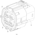
- Figure 1 shows an illustrative perspective view of a connector according to an exemplary embodiment of the present invention
- Figure 2 shows a longitudinal cross-sectional view of a connector according to an exemplary embodiment of the present invention
- Figure 3 shows an illustrative exploded view of a connector according to an exemplary embodiment of the present invention.
- the connector includes: an outer housing 1, an inner housing 2, a terminal (not shown), a shielding shell 3, a sealing ring 4, and a sealing ring positioning component 5.
- the outer housing 1 includes a first peripheral wall 11 and an inner cavity 101 surrounded by the first peripheral wall 11.
- the inner housing 2 is installed in the inner cavity 101 of the outer housing 1.
- the terminal is arranged in a terminal slot 201 of the inner housing 2.
- the inner housing 2 is arranged in the shielding shell 3.
- the sealing ring 4 is installed on the first peripheral wall 11.
- the sealing ring positioning component 5 is installed on the rear end of the first peripheral wall 11 and rests against the sealing ring 4.
- the shielding shell 3 includes an end wall 32 and two half shells 31a connected to the end wall 32. Two half shells 31a can be opened and closed. When the two half shells 31a are closed, the two half shells 31a are combined to form the outer peripheral wall 31 of the shielding shell 3.
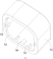
- Figure 4 shows an illustrative perspective view of the sealing ring positioning component 5 of the connector according to an exemplary embodiment of the present invention when viewed from the rear side;
- Figure 5 shows an illustrative perspective view of the sealing ring positioning component 5 of the connector according to an exemplary embodiment of the present invention when viewed from the front side;
- Figure 6 shows a transverse cross-sectional view of a connector according to an exemplary embodiment of the present invention, where the outer housing 1 is not shown;
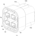
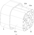
- Figure 7 shows an illustrative perspective view of a connector according to an exemplary embodiment of the present invention when viewed from the front side, where the outer housing 1 is not shown.
- a sealing ring positioning component 5 is disclosed.
- the sealing ring positioning component 5 is suitable for fitting on the outer housing 1 of the connector, and is used to position the sealing ring 4 on the outer housing 1.
- the sealing ring positioning component 5 includes: a peripheral wall 51 and a pushing protrusion 50.
- the pushing protrusion 50 is formed on the inner peripheral surface of the peripheral wall 51.
- the pushing protrusion 50 is used to push on the outer sides of the two half shells 31a of the shielding shell 3 of the connector, so that the splicing edges 31b of the two half shells 31a of the shielding shell 3 come into contact with each other without gap, thereby improving the electromagnetic shielding effect of the connector.
- the pushing protrusion 50 includes multiple protrusion ribs 53.
- Each protruding rib 53 extends along the axial direction of the sealing ring positioning component 5.
- Multiple protruding ribs 53 are distributed at intervals in the circumferential direction of the sealing ring positioning component 5, used to push the outer sides of the two half shells 31a of the shielding shell 3.
- the protruding rib 53 is plate-shaped and perpendicular to the peripheral wall 51.
- the structure of the pushing protrusion 50 is not limited to the illustrated embodiment.
- the pushing protrusion 50 may include multiple protruding ribs, each extending along the circumferential direction of the sealing ring positioning component 5. Multiple protruding ribs are distributed at intervals in the circumferential direction of the sealing ring positioning component 5, used to push the outer sides of the two half shells 31a of the shielding shell 3.
- the pushing protrusion 50 may include a single protrusion rib, which extends one circle along the circumferential direction of the sealing ring positioning component 5 to push the outer sides of the two half shells 31a of the shielding shell 3.
- a guide surface 53a is formed on the front end of the protruding rib 53, which is inclined to the axial direction of the sealing ring positioning component 5, used to guide the two half shells 31a of the shielding shell 3 into the accommodation space surrounded by multiple protruding ribs 53.
- the peripheral wall 51 of the sealing ring positioning component 5 has a front end and a rear end opposite to each other in the axial direction of the sealing ring positioning component 5.
- the front end of the peripheral wall 51 of the sealing ring positioning component 5 is used to rest against the rear side of the sealing ring 4 to axially position the sealing ring 4.
- multiple protruding ribs 53 are adjacent to the rear end of the peripheral wall 51, used to push the outer sides of the rear ends of the two half shells 3 1a of the shielding shell 3.
- the rear end of the shielding shell 3 is an opened end with a rear port.
- the sealing ring positioning component 5 also includes a positioning flange 52, which is formed on the rear end of the peripheral wall 51 and radially protrudes towards the inner side of the sealing ring positioning component 5.
- the positioning flange 52 is suitable for resting against the rear end face of a first peripheral wall 11 of the outer housing 1, and is used for axial positioning of the sealing ring positioning component 5.
- the rear end of the protruding rib 53 is connected to the inner side of the positioning flange 52.
- the sealing ring positioning component 5 further includes a buckle protrusion 55, which is formed on the inner surface of the peripheral wall 51.
- the buckle protrusion 55 is adapted to be engaged into a snapping slot 1c on the outer housing 1, and is used to fix the sealing ring positioning component 5 to the housing 1.
- the sealing ring positioning component 5 further includes a fool-proofing protrusion 54, which is formed on the inner surface of the peripheral wall 51.
- the fool-proofing protrusion 54 is suitable for inserting into the fool-proofing slot 1b on the outer housing 1 to ensure that the sealing ring positioning component 5 is installed in the correct orientation on the outer housing 1.
- the sealing ring positioning component 5 is an integral part.
- the sealing ring positioning component 5 can be an integrated injection molded part.
- a connector is also disclosed.
- the connector includes: an outer housing 1, inner housing 2, a terminal (not shown), a shielding shell 3, a sealing ring 4, and the aforementioned sealing ring positioning component 5.
- the outer housing 1 includes a first peripheral wall 11 and an inner cavity 101 surrounded by the first peripheral wall 11.
- the inner housing 2 is installed in the inner cavity 101 of the outer housing 1.
- the terminal is arranged in a terminal slot 201 of the inner housing 2.
- the inner housing 2 is arranged in the shielding shell 3.
- the sealing ring 4 is installed on the first peripheral wall 11.
- the sealing ring positioning component 5 is installed on the rear end of the first peripheral wall 11 and rests against the sealing ring 4.
- the shielding shell 3 includes an end wall 32 and two half shells 31a connected to the end wall 32. Two half shells 31a can be opened and closed. When the two half shells 31a are closed, the two half shells 31a are combined to form the outer peripheral wall 31 of the shielding shell 3.
- the pushing protrusion 50 is pushed onto the outer sides of the two half shells 31a, causing the splicing edges 31b of the two half shells 31a of the shielding shell 3 to come into contact with each other without gap.
- multiple slots 1a are formed on the rear end of the outer housing 1, and the multiple slots 1a are spaced in the circumferential direction of the outer housing 1.
- the multiple protruding ribs 53 on the sealing ring positioning component 5 are inserted into multiple slots 1a and rest against the outer sides of the two half shells 31a of the shielding shell 3.
- a snapping slot 1c is formed on the first peripheral wall 11, and the snapping slot 1c engages with the buckle protrusion 55 on the sealing ring positioning component 5 to fix the sealing ring positioning component 5 to the first peripheral wall 11.
- a fool-proofing slot 1b is formed on the first peripheral wall 11, and the fool-proofing slot 1b is engaged with the fool-proofing protrusion 54 on the sealing ring positioning component 5 to ensure that the sealing ring positioning component 5 is installed on the outer housing 1 in the correct orientation.
- the outer housing 1 further comprises a second peripheral wall 13 and a radial wall 14.
- the second peripheral wall 13 surrounds the first peripheral wall 11.
- the radial wall 14 is connected between the first peripheral wall 11 and the second peripheral wall 13.
- the sealing ring 4 is suitable for being radially compressed between the first peripheral wall 11 of the outer housing 1 and the mating housing to achieve sealing between the two.
- the front and rear sides of the sealing ring 4 respectively rest against the radial wall 14 and the sealing ring positioning component 5 to axially position the sealing ring 4.
- the housing 1 further includes a front end wall 12, which is connected to the front end of the first peripheral wall 11.
- a cable hole 102 is formed in the front end wall 12 of the outer housing 1, and a cable through hole 33 is formed in the end wall 32 of the shielding shell 3.
- the connector also includes a cable (not shown), with one end of the cable inserted into the terminal slot 201 through cable hole 102 and cable through hole 33 and electrically connected to the terminal (not shown).
- first elastic pieces 3a are formed on the rear edge of the outer peripheral wall 31 of the shielding shell 3, which are bent towards the interior of the shielding shell 3.
- the first elastic pieces 3a are used for elastic electrical contact with a mating shielding shell (not shown) of the mating connector.
- Multiple second elastic pieces 3b are formed on the edge of the cable through hole 33 of the shielding shell 3, bent towards the interior of the shielding shell 3, and are used for elastic electrical contact with a shielding layer (not shown) of the cable (not shown).
- the shielding shell 3 is in direct contact with the shielding layer of the cable, which can improve the electromagnetic shielding effect of the connector.
- multiple protruding ribs 53 on the sealing ring positioning component 5 rest against the outer side of the rear end of the shielding shell 3, providing support for multiple first elastic pieces 3a.
- the elastic contact force between multiple first elastic pieces 3a and the mating shielding shell can be increased, thereby ensuring reliable electrical contact between the shielding shell 3 and the mating shielding shell.
Landscapes
- Connector Housings Or Holding Contact Members (AREA)
- Details Of Connecting Devices For Male And Female Coupling (AREA)
Abstract
Description
- This application claims the benefit of Chinese Patent Application No.
CN202222385937.8 filed on September 8, 2022 - The present invention relates to a sealing ring positioning component and a connector comprising the sealing ring positioning component.
- In the prior art, a connector typically includes an outer housing, an inner housing, a terminal and a shielding shell. The inner housing is installed in the outer housing, the terminal is installed in the inner housing, and the shielding shell is sheathed on the outside of the inner housing. The outer housing is usually an integral injection molded part, while the shielding shell is usually an integral metal stamped part. The shielding shell usually includes an end wall and two half shells connected to the end wall, and the two half shells are combined to form the outer circumference wall of the shielding shell. In the prior art, in order to facilitate injection molding, the outer housing needs to have a certain slope, which causes the two half shells of the shielding shell cannot be closed, resulting in a certain gap between the splicing edges of the two half shells, which will reduce the electromagnetic shielding effect of the connector.
- The present invention has been made to overcome or alleviate at least one aspect of the above mentioned disadvantages.
- According to an aspect of the present invention, there is provided a sealing ring positioning component. The sealing ring positioning component is adapted to be fitted on an outer housing of a connector to positioning a sealing ring on the outer housing. The sealing ring positioning component comprises of a peripheral wall; and a pushing protrusion formed on an inner peripheral surface of the peripheral wall. The pushing protrusion is adapted to be pushed on the outer sides of two half shells of a shielding shell of the connector, so that the splicing edges of the two half shells of the shielding shell are in contact with each other.
- According to an exemplary embodiment of the present invention, the pushing protrusion comprises multiple protruding ribs extending along an axial direction of the sealing ring positioning component, the multiple protruding ribs are spaced in a circumferential direction of the sealing ring positioning component.
- According to another exemplary embodiment of the present invention, the pushing protrusion comprises multiple protruding ribs extending along a circumferential direction of the sealing ring positioning component, the multiple protruding ribs are spaced in the circumferential direction of the sealing ring positioning component.
- According to another exemplary embodiment of the present invention, the pushing protrusion comprises a single protruding rib continuously extending one circle along a circumferential direction of the sealing ring positioning component.
- According to another exemplary embodiment of the present invention, the protruding ribs are plate-shaped and perpendicular to the peripheral wall.
- According to another exemplary embodiment of the present invention, a guide surface is formed on the front end of the protruding ribs, the guide surface is inclined to the axial direction of the sealing ring positioning component and is used to guide the two half shells of the shielding shell into a space surrounded by the multiple protruding ribs.
- According to another exemplary embodiment of the present invention, the peripheral wall has a front end and a rear end that are opposite to each other in the axial direction of the sealing ring positioning component; the front end of the peripheral wall is used to rest against the rear side of the sealing ring to axially position the sealing ring.
- According to another exemplary embodiment of the present invention, the multiple protruding ribs are adjacent to the rear end of the peripheral wall and used to rest against the outer sides of the rear ends of the two half shells of the shielding shell.
- According to another exemplary embodiment of the present invention, the sealing ring positioning component further comprises a positioning flange which is formed on the rear end of the peripheral wall and radially protrudes towards the inner side of the sealing ring positioning component, the positioning flange is adapted to rest against a rear end face of a first peripheral wall of the outer housing for axially positioning the sealing ring positioning component.
- According to another exemplary embodiment of the present invention, the rear end of the protruding rib is connected to the inner side of the positioning flange.
- According to another exemplary embodiment of the present invention, the sealing ring positioning component further comprises a buckle protrusion formed on the inner surface of the peripheral wall, the buckle protrusion is adapted to be snapped into a snapping slot on the outer housing, for fixing the sealing ring positioning component to the outer housing.
- According to another exemplary embodiment of the present invention, the sealing ring positioning component further comprises a fool-proofing protrusion formed on the inner surface of the peripheral wall, the fool-proofing protrusion is adapted to be inserted into a fool-proofing slot on the outer housing to ensure that the sealing ring positioning component is installed in the correct orientation on the outer housing.
- According to another exemplary embodiment of the present invention, the sealing ring positioning component is an integral part.
- According to another aspect of the present invention, there is provided a connector. The connector comprises of an outer housing including a first peripheral wall and an inner cavity enclosed by the first peripheral wall; an inner housing installed in the inner cavity of the outer housing and formed with a terminal slot; a terminal provided in the terminal slot of the inner housing; a shielding shell in which the inner housing is provided; a sealing ring sleeved on the first peripheral wall of the outer housing; and the above sealing ring positioning component which is sleeved on the rear end of the first peripheral wall and rests against the sealing ring. The shielding shell includes an end wall and two half shells connected to the end wall, the two half shells are combined to form the outer peripheral wall of the shielding shell; the pushing protrusion of the sealing ring positioning component is pushed onto the outer sides of the two half shells, so that the splicing edges of the two half shells of the shielding shell are in contact with each other without a gap.
- According to an exemplary embodiment of the present invention, multiple slots are formed on the rear end of the outer housing, and the multiple slots are spaced in a circumferential direction of the outer housing; the pushing protrusion of the sealing ring positioning component includes multiple protrusion ribs, which are respectively inserted into the multiple slots and rest against the outer sides of the two half shells of the shielding shell.
- According to another exemplary embodiment of the present invention, a snapping slot is formed on the first peripheral wall, and the snapping slot is engaged with the buckle protrusion on the sealing ring positioning component to fix the sealing ring positioning component to the first peripheral wall.
- According to another exemplary embodiment of the present invention, a fool-proofing slot is formed on the first peripheral wall, and the fool-proofing slot is engaged with the fool-proofing protrusion on the sealing ring positioning component to ensure that the sealing ring positioning component is installed on the outer housing in the correct orientation.
- According to another exemplary embodiment of the present invention, the outer housing further comprises of a second peripheral wall surrounding the first peripheral wall; and a radial wall connected between the first peripheral wall and the second peripheral wall. A gap is formed between the first peripheral wall and the second peripheral wall to allow the insertion of a mating housing of a mating connector; the front and rear sides of the sealing ring respectively rest against the radial wall and the sealing ring positioning component to axially position the sealing ring; the sealing ring is adapted to be radially compressed between the mating housing and the first peripheral wall of the outer housing to achieve sealing between the two.
- According to another exemplary embodiment of the present invention, the outer housing further comprises a front end wall connected to the front end of the first peripheral wall, a cable hole is formed in the front end wall of the outer housing, and a cable through hole is formed in the end wall of the shielding shell. The connector further comprises a cable, one end of which is inserted into the terminal slot through the cable hole and the cable through hole and electrically connected to the terminal.
- According to another exemplary embodiment of the present invention, multiple first elastic pieces bent towards the interior of the shielding shell are formed on the rear edge of the outer peripheral wall of the shielding shell, and the first elastic pieces are used for electrical contact with a mating shielding shell of the mating connector; multiple second elastic pieces bent towards the interior of the shielding shell are formed on the edge of the cable through hole of the shielding shell, and the multiple second elastic pieces are used for electrical contact with a shielding layer of the cable; the pushing protrusions of the sealing ring positioning component rest against the outer side of the rear end of the shielding shell to provide support for the first elastic pieces.
- In the aforementioned exemplary embodiments of the present invention, the sealing ring positioning component can push the two half shells of the shielding shell towards the closed direction, so that the splicing edges of the two half shells of the shielding shell come into contact with each other without gap, improving the electromagnetic shielding effect of the connector.
- In addition, in the aforementioned exemplary embodiments of the present invention, the sealing ring positioning component can also provide support for the first elastic piece on the shielding shell to ensure reliable electrical contact between the shielding shell and the mating shielding shell. At the same time, the sealing ring positioning component can also push the shielding shell onto the inner housing, ensuring that the buckle structure on the shielding shell and the inner housing are reliably engaged to each other.
- The above and other features of the present invention will become more apparent by describing in detail exemplary embodiments thereof with reference to the accompanying drawings, in which:
-
Figure 1 shows an illustrative perspective view of a connector according to an exemplary embodiment of the present invention; -
Figure 2 shows a longitudinal cross-sectional view of a connector according to an exemplary embodiment of the present invention; -
Figure 3 shows an illustrative exploded view of a connector according to an exemplary embodiment of the present invention; -
Figure 4 shows an illustrative perspective view of the sealing ring positioning component of the connector according to an exemplary embodiment of the present invention when viewed from the rear side; -
Figure 5 shows an illustrative perspective view of the sealing ring positioning component of a connector according to an exemplary embodiment of the present invention when viewed from the front side; -
Figure 6 shows a transverse cross-sectional view of a connector according to an exemplary embodiment of the present invention, where the outer housing is not shown; and -
Figure 7 shows an illustrative perspective view of a connector according to an exemplary embodiment of the present invention when viewed from the front side, where the outer housing is not shown. - Exemplary embodiments of the present disclosure will be described hereinafter in detail with reference to the attached drawings, wherein the like reference numerals refer to the like elements. The present disclosure may, however, be embodied in many different forms and should not be construed as being limited to the embodiment set forth herein; rather, these embodiments are provided so that the present disclosure will be thorough and complete, and will fully convey the concept of the disclosure to those skilled in the art.
- In the following detailed description, for purposes of explanation, numerous specific details are set forth in order to provide a thorough understanding of the disclosed embodiments. It will be apparent, however, that one or more embodiments may be practiced without these specific details. In other instances, well-known structures and devices are schematically shown in order to simplify the drawing.
- According to a general concept of the present invention, there is provided a sealing ring positioning component. The sealing ring positioning component is adapted to be fitted on an outer housing of a connector to positioning a sealing ring on the outer housing. The sealing ring positioning component comprises of a peripheral wall; and a pushing protrusion formed on an inner peripheral surface of the peripheral wall. The pushing protrusion is adapted to be pushed on the outer sides of two half shells of a shielding shell of the connector, so that the splicing edges of the two half shells of the shielding shell are in contact with each other.
- According to another general concept of the present invention, there is provided a connector. The connector comprises of an outer housing including a first peripheral wall and an inner cavity enclosed by the first peripheral wall; an inner housing installed in the inner cavity of the outer housing and formed with a terminal slot; a terminal provided in the terminal slot of the inner housing; a shielding shell in which the inner housing is provided; a sealing ring sleeved on the first peripheral wall of the outer housing; and the above sealing ring positioning component which is sleeved on the rear end of the first peripheral wall and rests against the sealing ring. The shielding shell includes an end wall and two half shells connected to the end wall, the two half shells are combined to form the outer peripheral wall of the shielding shell; the pushing protrusion of the sealing ring positioning component is pushed onto the outer sides of the two half shells, so that the splicing edges of the two half shells of the shielding shell are in contact with each other without a gap.
-
Figure 1 shows an illustrative perspective view of a connector according to an exemplary embodiment of the present invention;Figure 2 shows a longitudinal cross-sectional view of a connector according to an exemplary embodiment of the present invention;Figure 3 shows an illustrative exploded view of a connector according to an exemplary embodiment of the present invention. - As shown in
Figures 1 to 3 , in the illustrated embodiments, the connector includes: anouter housing 1, aninner housing 2, a terminal (not shown), a shieldingshell 3, a sealingring 4, and a sealingring positioning component 5. Theouter housing 1 includes a firstperipheral wall 11 and aninner cavity 101 surrounded by the firstperipheral wall 11. Theinner housing 2 is installed in theinner cavity 101 of theouter housing 1. The terminal is arranged in aterminal slot 201 of theinner housing 2. Theinner housing 2 is arranged in the shieldingshell 3. The sealingring 4 is installed on the firstperipheral wall 11. The sealingring positioning component 5 is installed on the rear end of the firstperipheral wall 11 and rests against the sealingring 4. The shieldingshell 3 includes anend wall 32 and twohalf shells 31a connected to theend wall 32. Twohalf shells 31a can be opened and closed. When the twohalf shells 31a are closed, the twohalf shells 31a are combined to form the outerperipheral wall 31 of the shieldingshell 3. -
Figure 4 shows an illustrative perspective view of the sealingring positioning component 5 of the connector according to an exemplary embodiment of the present invention when viewed from the rear side;Figure 5 shows an illustrative perspective view of the sealingring positioning component 5 of the connector according to an exemplary embodiment of the present invention when viewed from the front side;Figure 6 shows a transverse cross-sectional view of a connector according to an exemplary embodiment of the present invention, where theouter housing 1 is not shown;Figure 7 shows an illustrative perspective view of a connector according to an exemplary embodiment of the present invention when viewed from the front side, where theouter housing 1 is not shown. - As shown in
Figures 1 to 7 , in an exemplary embodiment of the present invention, a sealingring positioning component 5 is disclosed. The sealingring positioning component 5 is suitable for fitting on theouter housing 1 of the connector, and is used to position the sealingring 4 on theouter housing 1. The sealingring positioning component 5 includes: aperipheral wall 51 and a pushingprotrusion 50. The pushingprotrusion 50 is formed on the inner peripheral surface of theperipheral wall 51. The pushingprotrusion 50 is used to push on the outer sides of the twohalf shells 31a of the shieldingshell 3 of the connector, so that the splicing edges 31b of the twohalf shells 31a of the shieldingshell 3 come into contact with each other without gap, thereby improving the electromagnetic shielding effect of the connector. - As shown in
Figures 1 to 7 , in the illustrated embodiment, the pushingprotrusion 50 includesmultiple protrusion ribs 53. Each protrudingrib 53 extends along the axial direction of the sealingring positioning component 5. Multiple protrudingribs 53 are distributed at intervals in the circumferential direction of the sealingring positioning component 5, used to push the outer sides of the twohalf shells 31a of the shieldingshell 3. In the illustrated embodiment, the protrudingrib 53 is plate-shaped and perpendicular to theperipheral wall 51. - However, please note that the structure of the pushing
protrusion 50 is not limited to the illustrated embodiment. For example, in another exemplary embodiment of the present invention, the pushingprotrusion 50 may include multiple protruding ribs, each extending along the circumferential direction of the sealingring positioning component 5. Multiple protruding ribs are distributed at intervals in the circumferential direction of the sealingring positioning component 5, used to push the outer sides of the twohalf shells 31a of the shieldingshell 3. - Although not shown, in another exemplary embodiment of the present invention, the pushing
protrusion 50 may include a single protrusion rib, which extends one circle along the circumferential direction of the sealingring positioning component 5 to push the outer sides of the twohalf shells 31a of the shieldingshell 3. - As shown in
Figures 1 to 7 , in the illustrated embodiments, a guide surface 53a is formed on the front end of the protrudingrib 53, which is inclined to the axial direction of the sealingring positioning component 5, used to guide the twohalf shells 31a of the shieldingshell 3 into the accommodation space surrounded by multiple protrudingribs 53. - As shown in
Figures 1 to 7 , in the illustrated embodiment, theperipheral wall 51 of the sealingring positioning component 5 has a front end and a rear end opposite to each other in the axial direction of the sealingring positioning component 5. The front end of theperipheral wall 51 of the sealingring positioning component 5 is used to rest against the rear side of the sealingring 4 to axially position the sealingring 4. - As shown in
Figures 1 to 7 , in the illustrated embodiments, multiple protrudingribs 53 are adjacent to the rear end of theperipheral wall 51, used to push the outer sides of the rear ends of the twohalf shells 3 1a of the shieldingshell 3. In the illustrated embodiment, the rear end of the shieldingshell 3 is an opened end with a rear port. - As shown in
Figures 1 to 7 , in the illustrated embodiment, the sealingring positioning component 5 also includes apositioning flange 52, which is formed on the rear end of theperipheral wall 51 and radially protrudes towards the inner side of the sealingring positioning component 5. Thepositioning flange 52 is suitable for resting against the rear end face of a firstperipheral wall 11 of theouter housing 1, and is used for axial positioning of the sealingring positioning component 5. In the illustrated embodiment, the rear end of the protrudingrib 53 is connected to the inner side of thepositioning flange 52. - As shown in
Figures 1 to 7 , in the illustrated embodiment, the sealingring positioning component 5 further includes abuckle protrusion 55, which is formed on the inner surface of theperipheral wall 51. Thebuckle protrusion 55 is adapted to be engaged into a snappingslot 1c on theouter housing 1, and is used to fix the sealingring positioning component 5 to thehousing 1. - As shown in
Figures 1 to 7 , in the illustrated embodiment, the sealingring positioning component 5 further includes a fool-proofingprotrusion 54, which is formed on the inner surface of theperipheral wall 51. The fool-proofingprotrusion 54 is suitable for inserting into the fool-proofing slot 1b on theouter housing 1 to ensure that the sealingring positioning component 5 is installed in the correct orientation on theouter housing 1. - As shown in
Figures 1 to 7 , in the illustrated embodiment, the sealingring positioning component 5 is an integral part. For example, the sealingring positioning component 5 can be an integrated injection molded part. - As shown in
Figures 1 to 7 , in an exemplary embodiment of the present invention, a connector is also disclosed. The connector includes: anouter housing 1,inner housing 2, a terminal (not shown), a shieldingshell 3, a sealingring 4, and the aforementioned sealingring positioning component 5. Theouter housing 1 includes a firstperipheral wall 11 and aninner cavity 101 surrounded by the firstperipheral wall 11. Theinner housing 2 is installed in theinner cavity 101 of theouter housing 1. The terminal is arranged in aterminal slot 201 of theinner housing 2. Theinner housing 2 is arranged in the shieldingshell 3. The sealingring 4 is installed on the firstperipheral wall 11. The sealingring positioning component 5 is installed on the rear end of the firstperipheral wall 11 and rests against the sealingring 4. The shieldingshell 3 includes anend wall 32 and twohalf shells 31a connected to theend wall 32. Twohalf shells 31a can be opened and closed. When the twohalf shells 31a are closed, the twohalf shells 31a are combined to form the outerperipheral wall 31 of the shieldingshell 3. The pushingprotrusion 50 is pushed onto the outer sides of the twohalf shells 31a, causing the splicing edges 31b of the twohalf shells 31a of the shieldingshell 3 to come into contact with each other without gap. - As shown in
Figures 1 to 7 , in the illustrated embodiment, multiple slots 1a are formed on the rear end of theouter housing 1, and the multiple slots 1a are spaced in the circumferential direction of theouter housing 1. The multiple protrudingribs 53 on the sealingring positioning component 5 are inserted into multiple slots 1a and rest against the outer sides of the twohalf shells 31a of the shieldingshell 3. - As shown in
Figures 1 to 7 , in the illustrated embodiments, a snappingslot 1c is formed on the firstperipheral wall 11, and the snappingslot 1c engages with thebuckle protrusion 55 on the sealingring positioning component 5 to fix the sealingring positioning component 5 to the firstperipheral wall 11. - As shown in
Figures 1 to 7 , in the illustrated embodiments, a fool-proofing slot 1b is formed on the firstperipheral wall 11, and the fool-proofing slot 1b is engaged with the fool-proofingprotrusion 54 on the sealingring positioning component 5 to ensure that the sealingring positioning component 5 is installed on theouter housing 1 in the correct orientation. - As shown in
Figures 1 to 7 , in the illustrated embodiment, theouter housing 1 further comprises a secondperipheral wall 13 and aradial wall 14. The secondperipheral wall 13 surrounds the firstperipheral wall 11. Theradial wall 14 is connected between the firstperipheral wall 11 and the secondperipheral wall 13. There is agap 103 between the firstperipheral wall 11 and the secondperipheral wall 13 to allow the insertion of a mating housing (not shown) of a mating connector (not shown). The sealingring 4 is suitable for being radially compressed between the firstperipheral wall 11 of theouter housing 1 and the mating housing to achieve sealing between the two. In the illustrated embodiment, the front and rear sides of the sealingring 4 respectively rest against theradial wall 14 and the sealingring positioning component 5 to axially position the sealingring 4. - As shown in
Figures 1 to 7 , in the illustrated embodiment, thehousing 1 further includes afront end wall 12, which is connected to the front end of the firstperipheral wall 11. Acable hole 102 is formed in thefront end wall 12 of theouter housing 1, and a cable throughhole 33 is formed in theend wall 32 of the shieldingshell 3. The connector also includes a cable (not shown), with one end of the cable inserted into theterminal slot 201 throughcable hole 102 and cable throughhole 33 and electrically connected to the terminal (not shown). - As shown in
Figures 1 to 7 , in the illustrated embodiments, multiple firstelastic pieces 3a are formed on the rear edge of the outerperipheral wall 31 of the shieldingshell 3, which are bent towards the interior of the shieldingshell 3. The firstelastic pieces 3a are used for elastic electrical contact with a mating shielding shell (not shown) of the mating connector. Multiple secondelastic pieces 3b are formed on the edge of the cable throughhole 33 of the shieldingshell 3, bent towards the interior of the shieldingshell 3, and are used for elastic electrical contact with a shielding layer (not shown) of the cable (not shown). The shieldingshell 3 is in direct contact with the shielding layer of the cable, which can improve the electromagnetic shielding effect of the connector. - As shown in
Figures 1 to 7 , in the illustrated embodiments, multiple protrudingribs 53 on the sealingring positioning component 5 rest against the outer side of the rear end of the shieldingshell 3, providing support for multiple firstelastic pieces 3a. In this way, the elastic contact force between multiple firstelastic pieces 3a and the mating shielding shell can be increased, thereby ensuring reliable electrical contact between the shieldingshell 3 and the mating shielding shell. - It should be appreciated for those skilled in this art that the above embodiments are intended to be illustrated, and not restrictive. For example, many modifications may be made to the above embodiments by those skilled in this art, and various features described in different embodiments may be freely combined with each other without conflicting in configuration or principle.
- Although several exemplary embodiments have been shown and described, it would be appreciated by those skilled in the art that various changes or modifications may be made in these embodiments without departing from the principles and spirit of the disclosure, the scope of which is defined in the claims and their equivalents.
- As used herein, an element recited in the singular and proceeded with the word "a" or "an" should be understood as not excluding plural of said elements or steps, unless such exclusion is explicitly stated. Furthermore, references to "one embodiment" of the present invention are not intended to be interpreted as excluding the existence of additional embodiments that also incorporate the recited features. Moreover, unless explicitly stated to the contrary, embodiments "comprising" or "having" an element or a plurality of elements having a particular property may include additional such elements not having that property.
Claims (15)
- A sealing ring positioning component, which is adapted to be fitted on an outer housing (1) of a connector to positioning a sealing ring (4) on the outer housing (1),wherein the sealing ring positioning component (5) comprises of:a peripheral wall (51); anda pushing protrusion (50) formed on an inner peripheral surface of the peripheral wall (51),wherein the pushing protrusion (50) is adapted to be pushed on the outer sides of two half shells (31a) of a shielding shell (3) of the connector, so that the splicing edges (31b) of the two half shells (31a) of the shielding shell (3) are in contact with each other.
- The sealing ring positioning component according to claim 1,wherein the pushing protrusion (50) comprises of
multiple protruding ribs (53) extending along an axial direction of the sealing ring positioning component (5),wherein the multiple protruding ribs (53) are spaced in a circumferential direction of the sealing ring positioning component (5). - The sealing ring positioning component according to claim 1,wherein the pushing protrusion (50) comprises of:
multiple protruding ribs extending along a circumferential direction of the sealing ring positioning component (5),wherein the multiple protruding ribs are spaced in the circumferential direction of the sealing ring positioning component (5). - The sealing ring positioning component according to claim 1,
wherein the pushing protrusion (50) comprises of:
a single protruding rib continuously extending one circle along a circumferential direction of the sealing ring positioning component (5). - The sealing ring positioning component according to claim 2,
wherein a guide surface (53a) is formed on the front end of the protruding ribs (53), the guide surface (53a) is inclined to the axial direction of the sealing ring positioning component (5) and is used to guide the two half shells (31a) of the shielding shell (3) into a space surrounded by the multiple protruding ribs (53). - The sealing ring positioning component according to claim 2,wherein the peripheral wall (51) has a front end and a rear end that are opposite to each other in the axial direction of the sealing ring positioning component (5);wherein the front end of the peripheral wall (51) is used to rest against the rear side of the sealing ring (4) to axially position the sealing ring (4);wherein the multiple protruding ribs (53) are adjacent to the rear end of the peripheral wall (51) and used to rest against the outer sides of the rear ends of the two half shells (31a) of the shielding shell (3).
- The sealing ring positioning component according to claim 2, further comprising:a positioning flange (52) which is formed on the rear end of the peripheral wall (51) and radially protrudes towards the inner side of the sealing ring positioning component (5),wherein the positioning flange (52) is adapted to rest against a rear end face of a first peripheral wall (11) of the outer housing (1) for axially positioning the sealing ring positioning component (5),wherein the rear end of the protruding rib (53) is connected to the inner side of the positioning flange (52).
- The sealing ring positioning component according to claim 1, further comprising:a buckle protrusion (55) formed on the inner surface of the peripheral wall (51),wherein the buckle protrusion (55) is adapted to be snapped into a snapping slot (1c) on the outer housing (1), for fixing the sealing ring positioning component (5) to the outer housing (1).
- The sealing ring positioning component according to claim 1, further comprising:a fool-proofing protrusion (54) formed on the inner surface of the peripheral wall (51),wherein the fool-proofing protrusion (54) is adapted to be inserted into a fool-proofing slot (1b) on the outer housing (1) to ensure that the sealing ring positioning component (5) is installed in the correct orientation on the outer housing (1).
- A connector, comprising:an outer housing (1) including a first peripheral wall (11) and an inner cavity (101) enclosed by the first peripheral wall (11);an inner housing (2) installed in the inner cavity (101) of the outer housing (1) and formed with a terminal slot (201);a terminal provided in the terminal slot (201) of the inner housing (2);a shielding shell (3) in which the inner housing (2) is provided;a sealing ring (4) sleeved on the first peripheral wall (11) of the outer housing (1); andthe sealing ring positioning component (5) according to any one of claims 1-13, which is sleeved on the rear end of the first peripheral wall (11) and rests against the sealing ring (4),wherein the shielding shell (3) includes an end wall (32) and two half shells (31a) connected to the end wall (32), the two half shells (31a) are combined to form the outer peripheral wall (31) of the shielding shell (3),wherein the pushing protrusion (50) of the sealing ring positioning component (5) is pushed onto the outer sides of the two half shells (31a), so that the splicing edges (31b) of the two half shells (31a) of the shielding shell (3) are in contact with each other without a gap.
- The connector according to claim 10,wherein multiple slots (1a) are formed on the rear end of the outer housing (1), and the multiple slots (1a) are spaced in a circumferential direction of the outer housing (1);wherein the pushing protrusion (50) of the sealing ring positioning component (5) includes multiple protrusion ribs (53), which are respectively inserted into the multiple slots (1a) and rest against the outer sides of the two half shells (31a) of the shielding shell (3).
- The connector according to claim 10,wherein a snapping slot (1c) is formed on the first peripheral wall (11), and the snapping slot (1c) is engaged with the buckle protrusion (55) on the sealing ring positioning component (5) to fix the sealing ring positioning component (5) to the first peripheral wall (11);wherein a fool-proofing slot (1b) is formed on the first peripheral wall (11), and the fool-proofing slot (1b) is engaged with the fool-proofing protrusion (54) on the sealing ring positioning component (5) to ensure that the sealing ring positioning component (5) is installed on the outer housing (1) in the correct orientation.
- The connector according to claim 10,wherein the outer housing (1) further comprises of:a second peripheral wall (13) surrounding the first peripheral wall (11); anda radial wall (14) connected between the first peripheral wall (11) and the second peripheral wall (13),wherein a gap (103) is formed between the first peripheral wall (11) and the second peripheral wall (13) to allow the insertion of a mating housing of a mating connector,wherein the front and rear sides of the sealing ring (4) respectively rest against the radial wall (14) and the sealing ring positioning component (5) to axially position the sealing ring (4),wherein the sealing ring (4) is adapted to be radially compressed between the mating housing and the first peripheral wall (11) of the outer housing (1) to achieve sealing between the two.
- The connector according to claim 13,wherein the outer housing (1) further comprises of:
a front end wall (12) connected to the front end of the first peripheral wall (11),wherein a cable hole (102) is formed in the front end wall (12) of the outer housing (1), and a cable through hole (33) is formed in the end wall (32) of the shielding shell (3),wherein the connector further comprises of:
a cable, one end of which is inserted into the terminal slot (201) through the cable hole (102) and the cable through hole (33) and electrically connected to the terminal. - The connector according to claim 14,wherein multiple first elastic pieces (3a) bent towards the interior of the shielding shell (3) are formed on the rear edge of the outer peripheral wall (31) of the shielding shell (3), and the first elastic pieces (3a) are used for electrical contact with a mating shielding shell of the mating connector;wherein multiple second elastic pieces (3b) bent towards the interior of the shielding shell (3) are formed on the edge of the cable through hole (33) of the shielding shell (3), and the multiple second elastic pieces (3b) are used for electrical contact with a shielding layer of the cable;wherein the pushing protrusions (50) of the sealing ring positioning component (5) rest against the outer side of the rear end of the shielding shell (3) to provide support for the first elastic pieces (3a).
Applications Claiming Priority (1)
| Application Number | Priority Date | Filing Date | Title |
|---|---|---|---|
| CN202222385937.8U CN218498449U (en) | 2022-09-08 | 2022-09-08 | Sealing ring positioning piece and connector |
Publications (2)
| Publication Number | Publication Date |
|---|---|
| EP4336668A1 true EP4336668A1 (en) | 2024-03-13 |
| EP4336668B1 EP4336668B1 (en) | 2025-07-16 |
Family
ID=85189828
Family Applications (1)
| Application Number | Title | Priority Date | Filing Date |
|---|---|---|---|
| EP23195341.5A Active EP4336668B1 (en) | 2022-09-08 | 2023-09-05 | Sealing ring positioning component and connector |
Country Status (3)
| Country | Link |
|---|---|
| EP (1) | EP4336668B1 (en) |
| JP (1) | JP2024039004A (en) |
| CN (1) | CN218498449U (en) |
Citations (4)
| Publication number | Priority date | Publication date | Assignee | Title |
|---|---|---|---|---|
| US8109789B2 (en) * | 2008-12-12 | 2012-02-07 | Tyco Electronics Corporation | Connector assembly with strain relief |
| US20170187150A1 (en) * | 2014-06-12 | 2017-06-29 | Delphi International Operations Luxembourg S.A.R.L | Shielded electrical connenctor and production method thereof |
| CN216981048U (en) * | 2022-03-07 | 2022-07-15 | 泰科电子(上海)有限公司 | Shielding shell for high-voltage connector, connector shell assembly, connector and connector assembly |
| EP4054021A1 (en) * | 2021-03-02 | 2022-09-07 | Aptiv Technologies Limited | Shielded connector assembly |
-
2022
- 2022-09-08 CN CN202222385937.8U patent/CN218498449U/en active Active
-
2023
- 2023-09-05 JP JP2023143344A patent/JP2024039004A/en active Pending
- 2023-09-05 EP EP23195341.5A patent/EP4336668B1/en active Active
Patent Citations (4)
| Publication number | Priority date | Publication date | Assignee | Title |
|---|---|---|---|---|
| US8109789B2 (en) * | 2008-12-12 | 2012-02-07 | Tyco Electronics Corporation | Connector assembly with strain relief |
| US20170187150A1 (en) * | 2014-06-12 | 2017-06-29 | Delphi International Operations Luxembourg S.A.R.L | Shielded electrical connenctor and production method thereof |
| EP4054021A1 (en) * | 2021-03-02 | 2022-09-07 | Aptiv Technologies Limited | Shielded connector assembly |
| CN216981048U (en) * | 2022-03-07 | 2022-07-15 | 泰科电子(上海)有限公司 | Shielding shell for high-voltage connector, connector shell assembly, connector and connector assembly |
Also Published As
| Publication number | Publication date |
|---|---|
| US20240088603A1 (en) | 2024-03-14 |
| JP2024039004A (en) | 2024-03-21 |
| CN218498449U (en) | 2023-02-17 |
| EP4336668B1 (en) | 2025-07-16 |
Similar Documents
| Publication | Publication Date | Title |
|---|---|---|
| US11394147B2 (en) | Connecting plug with central pin and lamella sleeve, method for forming the connecting plug and connecting socket with lamella sleeve | |
| EP2369689B1 (en) | Electrical connector | |
| JP2014053128A (en) | Electric connector assembly | |
| EP2346120A1 (en) | Shield connector and production method thereof | |
| US10530094B2 (en) | Electrical connector | |
| CN112886339B (en) | Ground terminal and connector comprising same | |
| EP2793315A1 (en) | Electrical connector having resilient latches | |
| EP4336668A1 (en) | Sealing ring positioning component and connector | |
| EP3629423B1 (en) | Electrical connector with plastic latch integrated into contact cavity | |
| EP4207509A1 (en) | Protection end cover, connector and connector assembly | |
| US12620752B2 (en) | Sealing ring positioning component and connector | |
| JP5246086B2 (en) | connector | |
| CN112448238B (en) | Connector shield with circumferential retaining elements | |
| US10971862B2 (en) | Cable connector having crimp structure | |
| EP4312316A1 (en) | Sub connector, connector, and connector assembly | |
| EP1122839B1 (en) | Modular jack | |
| US20190115689A1 (en) | Connector | |
| US6398597B1 (en) | Receptacle contact of a cable assembly and the cable assembly using the same | |
| US20240291192A1 (en) | Connector Terminal and Connector | |
| CN222440917U (en) | Charging stand and electric connector assembly | |
| US20250300403A1 (en) | Shielding Component and Connector | |
| EP4700996A1 (en) | Connector housing assembly and coaxial connector | |
| EP4700995A1 (en) | Connector housing assembly and coaxial connector | |
| JP2737668B2 (en) | Rubber stopper | |
| JP7792941B2 (en) | Electrical Connection Device |
Legal Events
| Date | Code | Title | Description |
|---|---|---|---|
| PUAI | Public reference made under article 153(3) epc to a published international application that has entered the european phase |
Free format text: ORIGINAL CODE: 0009012 |
|
| STAA | Information on the status of an ep patent application or granted ep patent |
Free format text: STATUS: THE APPLICATION HAS BEEN PUBLISHED |
|
| AK | Designated contracting states |
Kind code of ref document: A1 Designated state(s): AL AT BE BG CH CY CZ DE DK EE ES FI FR GB GR HR HU IE IS IT LI LT LU LV MC ME MK MT NL NO PL PT RO RS SE SI SK SM TR |
|
| STAA | Information on the status of an ep patent application or granted ep patent |
Free format text: STATUS: REQUEST FOR EXAMINATION WAS MADE |
|
| 17P | Request for examination filed |
Effective date: 20240823 |
|
| RBV | Designated contracting states (corrected) |
Designated state(s): AL AT BE BG CH CY CZ DE DK EE ES FI FR GB GR HR HU IE IS IT LI LT LU LV MC ME MK MT NL NO PL PT RO RS SE SI SK SM TR |
|
| GRAP | Despatch of communication of intention to grant a patent |
Free format text: ORIGINAL CODE: EPIDOSNIGR1 |
|
| STAA | Information on the status of an ep patent application or granted ep patent |
Free format text: STATUS: GRANT OF PATENT IS INTENDED |
|
| INTG | Intention to grant announced |
Effective date: 20250225 |
|
| GRAS | Grant fee paid |
Free format text: ORIGINAL CODE: EPIDOSNIGR3 |
|
| GRAA | (expected) grant |
Free format text: ORIGINAL CODE: 0009210 |
|
| STAA | Information on the status of an ep patent application or granted ep patent |
Free format text: STATUS: THE PATENT HAS BEEN GRANTED |
|
| P01 | Opt-out of the competence of the unified patent court (upc) registered |
Free format text: CASE NUMBER: APP_25103/2025 Effective date: 20250527 |
|
| AK | Designated contracting states |
Kind code of ref document: B1 Designated state(s): AL AT BE BG CH CY CZ DE DK EE ES FI FR GB GR HR HU IE IS IT LI LT LU LV MC ME MK MT NL NO PL PT RO RS SE SI SK SM TR |
|
| REG | Reference to a national code |
Ref country code: GB Ref legal event code: FG4D |
|
| REG | Reference to a national code |
Ref country code: CH Ref legal event code: EP |
|
| REG | Reference to a national code |
Ref country code: DE Ref legal event code: R096 Ref document number: 602023004833 Country of ref document: DE |
|
| REG | Reference to a national code |
Ref country code: IE Ref legal event code: FG4D |
|
| PGFP | Annual fee paid to national office [announced via postgrant information from national office to epo] |
Ref country code: DE Payment date: 20250722 Year of fee payment: 3 |
|
| PGFP | Annual fee paid to national office [announced via postgrant information from national office to epo] |
Ref country code: FR Payment date: 20250721 Year of fee payment: 3 Ref country code: AT Payment date: 20251020 Year of fee payment: 3 |
|
| REG | Reference to a national code |
Ref country code: NL Ref legal event code: MP Effective date: 20250716 |
|
| PG25 | Lapsed in a contracting state [announced via postgrant information from national office to epo] |
Ref country code: PT Free format text: LAPSE BECAUSE OF FAILURE TO SUBMIT A TRANSLATION OF THE DESCRIPTION OR TO PAY THE FEE WITHIN THE PRESCRIBED TIME-LIMIT Effective date: 20251117 |
|
| PG25 | Lapsed in a contracting state [announced via postgrant information from national office to epo] |
Ref country code: NL Free format text: LAPSE BECAUSE OF FAILURE TO SUBMIT A TRANSLATION OF THE DESCRIPTION OR TO PAY THE FEE WITHIN THE PRESCRIBED TIME-LIMIT Effective date: 20250716 |
|
| REG | Reference to a national code |
Ref country code: AT Ref legal event code: MK05 Ref document number: 1814972 Country of ref document: AT Kind code of ref document: T Effective date: 20250716 |
|
| PG25 | Lapsed in a contracting state [announced via postgrant information from national office to epo] |
Ref country code: IS Free format text: LAPSE BECAUSE OF FAILURE TO SUBMIT A TRANSLATION OF THE DESCRIPTION OR TO PAY THE FEE WITHIN THE PRESCRIBED TIME-LIMIT Effective date: 20251116 |
|
| PG25 | Lapsed in a contracting state [announced via postgrant information from national office to epo] |
Ref country code: NO Free format text: LAPSE BECAUSE OF FAILURE TO SUBMIT A TRANSLATION OF THE DESCRIPTION OR TO PAY THE FEE WITHIN THE PRESCRIBED TIME-LIMIT Effective date: 20251016 |
|
| REG | Reference to a national code |
Ref country code: LT Ref legal event code: MG9D |
|
| PG25 | Lapsed in a contracting state [announced via postgrant information from national office to epo] |
Ref country code: AT Free format text: LAPSE BECAUSE OF FAILURE TO SUBMIT A TRANSLATION OF THE DESCRIPTION OR TO PAY THE FEE WITHIN THE PRESCRIBED TIME-LIMIT Effective date: 20250716 |
|
| PG25 | Lapsed in a contracting state [announced via postgrant information from national office to epo] |
Ref country code: FI Free format text: LAPSE BECAUSE OF FAILURE TO SUBMIT A TRANSLATION OF THE DESCRIPTION OR TO PAY THE FEE WITHIN THE PRESCRIBED TIME-LIMIT Effective date: 20250716 |
|
| PG25 | Lapsed in a contracting state [announced via postgrant information from national office to epo] |
Ref country code: HR Free format text: LAPSE BECAUSE OF FAILURE TO SUBMIT A TRANSLATION OF THE DESCRIPTION OR TO PAY THE FEE WITHIN THE PRESCRIBED TIME-LIMIT Effective date: 20250716 |
|
| PG25 | Lapsed in a contracting state [announced via postgrant information from national office to epo] |
Ref country code: GR Free format text: LAPSE BECAUSE OF FAILURE TO SUBMIT A TRANSLATION OF THE DESCRIPTION OR TO PAY THE FEE WITHIN THE PRESCRIBED TIME-LIMIT Effective date: 20251017 |
|
| PG25 | Lapsed in a contracting state [announced via postgrant information from national office to epo] |
Ref country code: SE Free format text: LAPSE BECAUSE OF FAILURE TO SUBMIT A TRANSLATION OF THE DESCRIPTION OR TO PAY THE FEE WITHIN THE PRESCRIBED TIME-LIMIT Effective date: 20250716 |
|
| PG25 | Lapsed in a contracting state [announced via postgrant information from national office to epo] |
Ref country code: LV Free format text: LAPSE BECAUSE OF FAILURE TO SUBMIT A TRANSLATION OF THE DESCRIPTION OR TO PAY THE FEE WITHIN THE PRESCRIBED TIME-LIMIT Effective date: 20250716 |
|
| PG25 | Lapsed in a contracting state [announced via postgrant information from national office to epo] |
Ref country code: BG Free format text: LAPSE BECAUSE OF FAILURE TO SUBMIT A TRANSLATION OF THE DESCRIPTION OR TO PAY THE FEE WITHIN THE PRESCRIBED TIME-LIMIT Effective date: 20250716 Ref country code: PL Free format text: LAPSE BECAUSE OF FAILURE TO SUBMIT A TRANSLATION OF THE DESCRIPTION OR TO PAY THE FEE WITHIN THE PRESCRIBED TIME-LIMIT Effective date: 20250716 |
|
| PG25 | Lapsed in a contracting state [announced via postgrant information from national office to epo] |
Ref country code: RS Free format text: LAPSE BECAUSE OF FAILURE TO SUBMIT A TRANSLATION OF THE DESCRIPTION OR TO PAY THE FEE WITHIN THE PRESCRIBED TIME-LIMIT Effective date: 20251016 |
|
| PG25 | Lapsed in a contracting state [announced via postgrant information from national office to epo] |
Ref country code: ES Free format text: LAPSE BECAUSE OF FAILURE TO SUBMIT A TRANSLATION OF THE DESCRIPTION OR TO PAY THE FEE WITHIN THE PRESCRIBED TIME-LIMIT Effective date: 20250716 |
|
| PG25 | Lapsed in a contracting state [announced via postgrant information from national office to epo] |
Ref country code: RO Free format text: LAPSE BECAUSE OF FAILURE TO SUBMIT A TRANSLATION OF THE DESCRIPTION OR TO PAY THE FEE WITHIN THE PRESCRIBED TIME-LIMIT Effective date: 20250716 |
|
| PG25 | Lapsed in a contracting state [announced via postgrant information from national office to epo] |
Ref country code: SM Free format text: LAPSE BECAUSE OF FAILURE TO SUBMIT A TRANSLATION OF THE DESCRIPTION OR TO PAY THE FEE WITHIN THE PRESCRIBED TIME-LIMIT Effective date: 20250716 |
|
| PG25 | Lapsed in a contracting state [announced via postgrant information from national office to epo] |
Ref country code: DK Free format text: LAPSE BECAUSE OF FAILURE TO SUBMIT A TRANSLATION OF THE DESCRIPTION OR TO PAY THE FEE WITHIN THE PRESCRIBED TIME-LIMIT Effective date: 20250716 |
|
| PG25 | Lapsed in a contracting state [announced via postgrant information from national office to epo] |
Ref country code: IT Free format text: LAPSE BECAUSE OF FAILURE TO SUBMIT A TRANSLATION OF THE DESCRIPTION OR TO PAY THE FEE WITHIN THE PRESCRIBED TIME-LIMIT Effective date: 20250716 |
|
| PG25 | Lapsed in a contracting state [announced via postgrant information from national office to epo] |
Ref country code: CZ Free format text: LAPSE BECAUSE OF FAILURE TO SUBMIT A TRANSLATION OF THE DESCRIPTION OR TO PAY THE FEE WITHIN THE PRESCRIBED TIME-LIMIT Effective date: 20250716 |
|
| PG25 | Lapsed in a contracting state [announced via postgrant information from national office to epo] |
Ref country code: EE Free format text: LAPSE BECAUSE OF FAILURE TO SUBMIT A TRANSLATION OF THE DESCRIPTION OR TO PAY THE FEE WITHIN THE PRESCRIBED TIME-LIMIT Effective date: 20250716 Ref country code: SK Free format text: LAPSE BECAUSE OF FAILURE TO SUBMIT A TRANSLATION OF THE DESCRIPTION OR TO PAY THE FEE WITHIN THE PRESCRIBED TIME-LIMIT Effective date: 20250716 |