EP4336665A1 - Connector module including a terminal reteiner, connector and connector assembly - Google Patents
Connector module including a terminal reteiner, connector and connector assembly Download PDFInfo
- Publication number
- EP4336665A1 EP4336665A1 EP23195586.5A EP23195586A EP4336665A1 EP 4336665 A1 EP4336665 A1 EP 4336665A1 EP 23195586 A EP23195586 A EP 23195586A EP 4336665 A1 EP4336665 A1 EP 4336665A1
- Authority
- EP
- European Patent Office
- Prior art keywords
- terminal
- locking
- insulator
- slot
- locking member
- Prior art date
- Legal status (The legal status is an assumption and is not a legal conclusion. Google has not performed a legal analysis and makes no representation as to the accuracy of the status listed.)
- Pending
Links
Images



Classifications
-
- H—ELECTRICITY
- H01—ELECTRIC ELEMENTS
- H01R—ELECTRICALLY-CONDUCTIVE CONNECTIONS; STRUCTURAL ASSOCIATIONS OF A PLURALITY OF MUTUALLY-INSULATED ELECTRICAL CONNECTING ELEMENTS; COUPLING DEVICES; CURRENT COLLECTORS
- H01R13/00—Details of coupling devices of the kinds covered by groups H01R12/70 or H01R24/00 - H01R33/00
- H01R13/40—Securing contact members in or to a base or case; Insulating of contact members
- H01R13/42—Securing in a demountable manner
- H01R13/436—Securing a plurality of contact members by one locking piece or operation
- H01R13/4361—Insertion of locking piece perpendicular to direction of contact insertion
- H01R13/4362—Insertion of locking piece perpendicular to direction of contact insertion comprising a temporary and a final locking position
Definitions
- the present invention relates to a connector module, a connector including the connector module, and a connector assembly including the connector.
- a connector typically includes an insulator, a terminal, and a terminal locking member.
- a terminal slot and a locking member installation slot are formed in the insulator.
- the terminal is inserted into the terminal slot on the insulator, the terminal locking member is installed into the locking member installation slot on the insulator.
- the terminal locking member is usually able to be moved between a pre locking position separated from the terminal and a final locking position engaged with the terminal.
- the terminal typically has a locking spring (commonly referred to as a primary lock) that latch onto the inner wall of the terminal slot.
- the terminal locking member (usually referred to as a secondary lock) and the locking spring together lock the terminal in the terminal slot. Therefore, before pulling out the terminal from the terminal slot, it is necessary to first move the terminal locking member from the final locking position to the pre locking position, then insert the operating tool into the terminal slot to drive the locking spring to the unlocking position that is separated from the inner wall of the terminal slot, and finally pull out the terminal from the terminal slot.
- operators sometimes forget to move the terminal locking member from the final locking position to the pre locking position, which can cause damage to the terminal locking member or terminal when the terminal is pulled out.
- the present invention has been made to overcome or alleviate at least one aspect of the above mentioned disadvantages.
- a connector module comprising of: an insulator formed with a terminal slot for accommodating a terminal and a tool insertion port communicated with the terminal slot; and a terminal locking member installed on the insulator and movable between a pre locking position separated from the terminal and a final locking position engaged with the terminal.
- the terminal locking member is in the pre locking position, the tool insertion port is not blocked by the terminal locking member to allow an operating tool to be inserted into the terminal slot through the tool insertion port to drive a locking spring of the terminal to an unlocking position separated from the insulator.
- the tool insertion port is blocked by the terminal locking member to prevent the operating tool from being inserted into the terminal slot through the tool insertion port, thereby preventing the locking spring of the terminal from being accidentally unlocked by the operating tool.
- a locking part slot communicated with the terminal slot is also formed in the insulator.
- the terminal locking member comprises of a main body part; a locking part connected to the main body part and inserted into the locking part slot; and a blocking part connected to the main body part to block the tool insertion port.
- an engagement slot is also formed in the insulator; the terminal locking member further comprises an engagement part connected to the main body part and inserted into the engagement slot.
- An engagement protrusion is formed on the engagement part, and an engagement surface is formed on the side wall of the engagement slot.
- a pair of elastic arms are formed on the main body part, protrusion parts are formed on both sides of the pair of elastic arms facing each other, and a pre locking surface is formed on the lower side of the protrusion part;
- a raised rib is formed on the insulator, mating protrusion parts are formed on both sides of the raised ribs, and a mating pre locking surface is formed on the upper side of the mating protrusion part;
- a final locking surface is formed on the upper side of the protrusion part of the terminal locking member, and a mating final locking surface is formed on the lower side of the mating protrusion part of the insulator; when the terminal locking member is in the final locking position, the final locking surface on the terminal locking member is engaged with the mating final locking surface on the insulator to prevent the terminal locking member from being moved towards the pre locking position and maintain the terminal locking member in the final locking position.
- an accommodating recess is formed on the insulator for receiving the main body part, and the main body part is installed in the accommodating recess.
- the top surface of the main body part is flush with the top surface of the insulator.
- the main body part is in a flat plate shape, and the raised rib protrudes a predetermined height from the bottom surface of the accommodating recess and is inserted between the pair of elastic arms.
- the bottom surface of the main body part is pressed against the bottom surface of the accommodating recess to limit the terminal locking member at the final locking position.
- the locking part slot, the tool insertion port, and the engagement slot are communicated with the accommodating recess, and the engagement slot is communicated with the locking part slot and the terminal slot.
- the terminal slot extends along a length direction of the insulator, and the locking part slot extends along a width direction of the insulator; the front end face of the terminal locking member is flush with the front end face of the insulator, and the tool insertion port is formed on the front end face of the insulator.
- the locking part extends continuously along the width direction of the insulator, the locking part has a locking surface perpendicular to the length direction of the insulator, the locking surface is used to rest against the terminal to lock the terminal in the terminal slot.
- the main body part is rectangular, and the engagement parts are respectively formed at the four corner parts of the main body part; the locking part is connected between two engagement parts on the rear side of the main body part.
- an engagement hole is formed in the protrusion part of the elastic arm, the engagement hole is used to engage with an unlocking tool for driving the protrusion parts of the pair of elastic arms to an unlocking position separated from the mating protrusions.
- the elastic arm extends along the length direction of the insulator, and both ends of the elastic arm are fixed, the protrusion part is formed on the middle part of the elastic arm.
- the terminal module further comprises a terminal which is inserted into the terminal slot of the insulator, the terminal has a locking spring that locks onto the inner wall of the terminal slot.
- multiple terminal slots are formed in the insulator, and the connector module includes multiple terminals, which are respectively inserted into the multiple terminal slots; the locking part slot is communicated with the multiple terminal slots, and the locking part partially extends into the multiple terminal slots through the locking part slot to simultaneously lock the multiple terminals.
- a connector comprising of a housing; and the above connector module which is installed in the housing.
- a connector assembly comprising of the above connector; and a mating connector which is mated with the connector.
- the operating tool for unlocking the locking spring of the terminal cannot be inserted into the terminal slot when the terminal locking member is in the final locking position. Therefore, it can avoid the problem of accidentally unlocking the locking spring when the terminal locking member is in the final locking position, thereby preventing operators from mis operating and improving the safety of connector use.
- a connector module comprising of an insulator formed with a terminal slot for accommodating a terminal and a tool insertion port communicated with the terminal slot; and a terminal locking member installed on the insulator and movable between a pre locking position separated from the terminal and a final locking position engaged with the terminal.
- the terminal locking member is in the pre locking position, the tool insertion port is not blocked by the terminal locking member to allow an operating tool to be inserted into the terminal slot through the tool insertion port to drive a locking spring of the terminal to an unlocking position separated from the insulator.
- the tool insertion port is blocked by the terminal locking member to prevent the operating tool from being inserted into the terminal slot through the tool insertion port, thereby preventing the locking spring of the terminal from being accidentally unlocked by the operating tool.
- a connector comprising of a housing; and the above connector module which is installed in the housing.
- the connector assembly comprises of the above connector; and a mating connector which is mated with the connector.
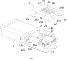
- Figure 1 shows an illustrative exploded view of a connector module according to an exemplary embodiment of the present invention
- Figure 2 shows an illustrative exploded cross-sectional view of a connector module according to an exemplary embodiment of the present invention
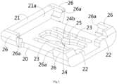
- Figure 3 shows an illustrative perspective view of the terminal locking member 2 of the connector module according to an exemplary embodiment of the present invention when viewed from the bottom.
- a connector module is disclosed.
- the connector module includes an insulator 1 and a terminal locking member 2 (commonly referred to as a secondary lock).
- the terminal locking member 2 is used to lock the terminals 3 (see Figure 5 ) in insulator 1.
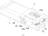
- Figure 4 shows an illustrative perspective view of a connector module according to an exemplary embodiment of the present invention, wherein the terminal locking member 2 is in a pre locking position
- Figure 5 shows a longitudinal cross-sectional view of a connector module according to an exemplary embodiment of the present invention, wherein the terminal locking member 2 is in a pre locking position
- Figure 6 shows a longitudinal cross-sectional view of a connector module according to an exemplary embodiment of the present invention, wherein the terminal locking member 2 is in the pre locking position and the inserted operating tool 4 is shown
- Figure 7 shows an illustrative perspective view of a connector module according to an exemplary embodiment of the present invention, wherein the terminal locking member 2 is in the final locking position
- Figure 8 shows a longitudinal cross-sectional view of a connector module according to an exemplary embodiment of the present invention, with terminal locking member 2 in the final locking position.
- a terminal slot 101 for accommodating the terminal 3 and a tool insertion port 12 connected to the terminal slot 101 are formed in the insulator 1.
- the terminal locking member 2 is installed on the insulator 1 and can be moved between a pre locking position separated from the terminal 3 and a final locking position engaged with the terminal 3.
- the terminal 3 can be inserted into and pulled out of the terminal slot 101.
- the terminal locking member 2 is in the final locking position, the inserted terminal 3 is locked in the terminal slot 101 by the terminal locking member 2.
- the tool insertion port 12 is not blocked by the terminal locking member 2 to allow an operating tool 4 to be inserted into the terminal slot 101 through the tool insertion port 12, thereby enabling a locking spring 31 of the terminal 3 to be moved to an unlocked position separated from the insulator 1 by the inserted operating tool 4.
- a locking part slot 11 connected to the terminal slot 101 is also formed in the insulator 1.
- the terminal locking member 2 includes a main body part 20, a locking part 21, and a blocking part 22.
- the locking part 21 is connected to the main body part 20 and inserted into the locking part slot 11.
- the blocking part 22 is connected to the main body part 20 for blocking the tool insertion port 12.
- an engagement slot 16 is also formed in the insulator 1.
- the terminal locking member 2 also includes an engagement part 26, which is connected to the main body part 20 and inserted into the engagement slot 16.
- An engagement protrusion 26a is formed on the engagement part 26, and an engagement surface 16a is formed on the side wall of the engagement slot 16.
- the engagement protrusion 26a is pressed against the engagement surface 16a to prevent the terminal locking member 2 from being moved in the direction of separation from the insulator 1.
- the engagement surface 16a is an inclined plane that can provide a predetermined blocking force.
- a pair of elastic arms 23 are formed on the main body part 20.
- Protrusion parts 24 are formed on both sides of the pair of elastic arms 23 facing each other, and a pre locking surface 24a is formed on the lower side of the protrusion parts 24.
- a raised ribs 13 is formed on insulator 1
- mating protrusion parts 14 are formed on both sides of the raised rib 13
- a mating pre locking surface 14a is formed on the upper side of the mating protrusion part 14.
- the pre locking surface 24a on the terminal locking member 2 is pressed against the mating pre locking surface 14a on the insulator 1 to prevent the terminal locking member 2 from being moved towards the final locking position and to hold the terminal locking member 2 in the pre locking position.
- a final locking surface 24b is formed on the upper side of the protrusion part 24 of the terminal locking member 2, and a mating final locking surface 14b is formed on the lower side of the mating protrusion part 14 of the insulator 1.
- an accommodating recess 120 is formed on the insulator 1 for receiving the main body part 20, and the main body part 20 is installed in the accommodating recess 120.
- the main body part 20 is in a flat plate shape, and the raised rib 13 protrudes from the bottom surface of the accommodating recess 120 to a predetermined height and is inserted between the pair of elastic arms 23.
- the locking part slot 11, the tool insertion port 12, and the engagement slot 16 are connected to the the accommodating recess 120; And the engagement slot 16 is connected to the locking part slot 11 and the terminal slot 101.
- the terminal slot 101 extends along the length direction of insulator 1
- the locking part slot 11 extends along the width direction of insulator 1.
- the front end face of the terminal locking member 2 is flush with the front end face of insulator 1, and the tool insertion port 12 is formed on the front end face of insulator 1.
- the terminal 3 is inserted into the terminal slot 101 along the length direction of insulator 1.
- the locking part 21 extends continuously along the width direction of the insulator 1, and has a locking surface 21a perpendicular to the length direction of the insulator 1.
- the locking surface 21a is used to rest against the terminal 3 to lock the terminal 3 in the terminal slot 101.
- the main body part 20 is rectangular, and the engagement part 26 is formed at each of the four corner parts of the main body part 20.
- the locking part 21 is connected between two engagement parts 26 on the rear side of the main body part 20.
- an engagement hole 25 is formed on the protrusion part 24 of the elastic arm 23, which is used to engage with an unlocking tool (not shown) to drive the protrusion parts 24 of the pair of elastic arms 23 to the unlocking position separated from the mating protrusion part 14 through the unlocking tool.
- the elastic arm 23 extends along the length direction of the insulator 1 and its two ends are fixed, with the protrusion part 24 located on the middle part of the elastic arm 23.
- the connector module further includes a terminal 3, which is inserted into the terminal slot 101 of the insulator 1.
- the terminal 3 has a locking spring 31 (commonly referred to as a primary lock) that is locked to the inner wall of the terminal slot 101.
- multiple terminal slots 101 are formed in the insulator 1, and the connector module includes multiple terminals 3, which are respectively inserted into multiple terminal slots 101.
- the locking part slot 11 is connected to multiple terminal slots 101, and the locking part 21 partially extends into multiple terminal slots 101 through the locking part slot 11 to simultaneously lock multiple terminals 3.
- Figure 9 shows an illustrative perspective view of a connector according to an exemplary embodiment of the present invention.
- a connector is also disclosed.
- the connector includes: a housing 5 and the aforementioned connector module.
- the connector module is installed in the housing 5.
- a connector assembly is also disclosed.
- the connector assembly includes the aforementioned connector and a mating connector (not shown) which is mated with the aforementioned connector.
Landscapes
- Connector Housings Or Holding Contact Members (AREA)
Abstract
Description
- This application claims the benefit of Chinese Patent Application No.
CN202222401084.2 filed on September 9, 2022 - The present invention relates to a connector module, a connector including the connector module, and a connector assembly including the connector.
- In the prior art, a connector typically includes an insulator, a terminal, and a terminal locking member. A terminal slot and a locking member installation slot are formed in the insulator. The terminal is inserted into the terminal slot on the insulator, the terminal locking member is installed into the locking member installation slot on the insulator. For ease of operation, the terminal locking member is usually able to be moved between a pre locking position separated from the terminal and a final locking position engaged with the terminal.
- In the prior art, the terminal typically has a locking spring (commonly referred to as a primary lock) that latch onto the inner wall of the terminal slot. The terminal locking member (usually referred to as a secondary lock) and the locking spring together lock the terminal in the terminal slot. Therefore, before pulling out the terminal from the terminal slot, it is necessary to first move the terminal locking member from the final locking position to the pre locking position, then insert the operating tool into the terminal slot to drive the locking spring to the unlocking position that is separated from the inner wall of the terminal slot, and finally pull out the terminal from the terminal slot. However, in practical applications, operators sometimes forget to move the terminal locking member from the final locking position to the pre locking position, which can cause damage to the terminal locking member or terminal when the terminal is pulled out.
- The present invention has been made to overcome or alleviate at least one aspect of the above mentioned disadvantages.
- According to an aspect of the present invention, there is provided a connector module. The connector module comprises of: an insulator formed with a terminal slot for accommodating a terminal and a tool insertion port communicated with the terminal slot; and a terminal locking member installed on the insulator and movable between a pre locking position separated from the terminal and a final locking position engaged with the terminal. When the terminal locking member is in the pre locking position, the tool insertion port is not blocked by the terminal locking member to allow an operating tool to be inserted into the terminal slot through the tool insertion port to drive a locking spring of the terminal to an unlocking position separated from the insulator. When the terminal locking member is in the final locking position, the tool insertion port is blocked by the terminal locking member to prevent the operating tool from being inserted into the terminal slot through the tool insertion port, thereby preventing the locking spring of the terminal from being accidentally unlocked by the operating tool.
- According to an exemplary embodiment of the present invention, a locking part slot communicated with the terminal slot is also formed in the insulator. The terminal locking member comprises of a main body part; a locking part connected to the main body part and inserted into the locking part slot; and a blocking part connected to the main body part to block the tool insertion port. When the terminal locking member is in the pre locking position, the locking part is separated from the terminal, and the tool insertion port is not blocked by the blocking part. When the terminal locking member is in the final locking position, the locking part is engaged with the terminal, and the tool insertion port is blocked by the blocking part.
- According to another exemplary embodiment of the present invention, an engagement slot is also formed in the insulator; the terminal locking member further comprises an engagement part connected to the main body part and inserted into the engagement slot. An engagement protrusion is formed on the engagement part, and an engagement surface is formed on the side wall of the engagement slot. When the terminal locking member is in the pre locking position, the engagement protrusion is engaged with the engagement surface to prevent the terminal locking member from being moved in a direction of separation from the insulator.
- According to another exemplary embodiment of the present invention, a pair of elastic arms are formed on the main body part, protrusion parts are formed on both sides of the pair of elastic arms facing each other, and a pre locking surface is formed on the lower side of the protrusion part; a raised rib is formed on the insulator, mating protrusion parts are formed on both sides of the raised ribs, and a mating pre locking surface is formed on the upper side of the mating protrusion part; when the terminal locking member is in the pre locking position, the pre locking surface on the terminal locking member is engaged with the mating pre locking surface on the insulator to prevent the terminal locking member from being moved towards the final locking position and maintain the terminal locking member in the pre locking position.
- According to another exemplary embodiment of the present invention, a final locking surface is formed on the upper side of the protrusion part of the terminal locking member, and a mating final locking surface is formed on the lower side of the mating protrusion part of the insulator; when the terminal locking member is in the final locking position, the final locking surface on the terminal locking member is engaged with the mating final locking surface on the insulator to prevent the terminal locking member from being moved towards the pre locking position and maintain the terminal locking member in the final locking position.
- According to another exemplary embodiment of the present invention, an accommodating recess is formed on the insulator for receiving the main body part, and the main body part is installed in the accommodating recess.
- According to another exemplary embodiment of the present invention, when the terminal locking member is in the final locking position, the top surface of the main body part is flush with the top surface of the insulator.
- According to another exemplary embodiment of the present invention, the main body part is in a flat plate shape, and the raised rib protrudes a predetermined height from the bottom surface of the accommodating recess and is inserted between the pair of elastic arms.
- According to another exemplary embodiment of the present invention, when the terminal locking member is in the final locking position, the bottom surface of the main body part is pressed against the bottom surface of the accommodating recess to limit the terminal locking member at the final locking position.
- According to another exemplary embodiment of the present invention, the locking part slot, the tool insertion port, and the engagement slot are communicated with the accommodating recess, and the engagement slot is communicated with the locking part slot and the terminal slot.
- According to another exemplary embodiment of the present invention, the terminal slot extends along a length direction of the insulator, and the locking part slot extends along a width direction of the insulator; the front end face of the terminal locking member is flush with the front end face of the insulator, and the tool insertion port is formed on the front end face of the insulator.
- According to another exemplary embodiment of the present invention, the locking part extends continuously along the width direction of the insulator, the locking part has a locking surface perpendicular to the length direction of the insulator, the locking surface is used to rest against the terminal to lock the terminal in the terminal slot.
- According to another exemplary embodiment of the present invention, the main body part is rectangular, and the engagement parts are respectively formed at the four corner parts of the main body part; the locking part is connected between two engagement parts on the rear side of the main body part.
- According to another exemplary embodiment of the present invention, an engagement hole is formed in the protrusion part of the elastic arm, the engagement hole is used to engage with an unlocking tool for driving the protrusion parts of the pair of elastic arms to an unlocking position separated from the mating protrusions.
- According to another exemplary embodiment of the present invention, the elastic arm extends along the length direction of the insulator, and both ends of the elastic arm are fixed, the protrusion part is formed on the middle part of the elastic arm.
- According to another exemplary embodiment of the present invention, the terminal module further comprises a terminal which is inserted into the terminal slot of the insulator, the terminal has a locking spring that locks onto the inner wall of the terminal slot.
- According to another exemplary embodiment of the present invention, multiple terminal slots are formed in the insulator, and the connector module includes multiple terminals, which are respectively inserted into the multiple terminal slots; the locking part slot is communicated with the multiple terminal slots, and the locking part partially extends into the multiple terminal slots through the locking part slot to simultaneously lock the multiple terminals.
- According to another aspect of the present invention, there is provided a connector. The connector comprises of a housing; and the above connector module which is installed in the housing.
- According to another aspect of the present invention, there is provided a connector assembly. The connector assembly comprises of the above connector; and a mating connector which is mated with the connector.
- In the aforementioned exemplary embodiments of the present invention, the operating tool for unlocking the locking spring of the terminal cannot be inserted into the terminal slot when the terminal locking member is in the final locking position. Therefore, it can avoid the problem of accidentally unlocking the locking spring when the terminal locking member is in the final locking position, thereby preventing operators from mis operating and improving the safety of connector use.
- The above and other features of the present invention will become more apparent by describing in detail exemplary embodiments thereof with reference to the accompanying drawings, in which:
-
Figure 1 shows an illustrative exploded view of a connector module according to an exemplary embodiment of the present invention; -
Figure 2 shows an illustrative exploded cross-sectional view of a connector module according to an exemplary embodiment of the present invention; -
Figure 3 shows an illustrative perspective view of a terminal locking member of a connector module according to an exemplary embodiment of the present invention when viewed from the bottom; -
Figure 4 shows an illustrative perspective view of a connector module according to an exemplary embodiment of the present invention, wherein the terminal locking member is in a pre locking position; -
Figure 5 shows a longitudinal cross-sectional view of a connector module according to an exemplary embodiment of the present invention, wherein the terminal locking member is in a pre locking position; -
Figure 6 shows a longitudinal cross-sectional view of a connector module according to an exemplary embodiment of the present invention, wherein the terminal locking member is in a pre locking position and the insertion operation tool is shown; -
Figure 7 shows an illustrative perspective view of a connector module according to an exemplary embodiment of the present invention, wherein the terminal locking member is in the final locking position; -
Figure 8 shows a longitudinal cross-sectional view of a connector module according to an exemplary embodiment of the present invention, wherein the terminal locking member is in the final locking position; and -
Figure 9 shows an illustrative perspective view of a connector according to an exemplary embodiment of the present invention. - Exemplary embodiments of the present disclosure will be described hereinafter in detail with reference to the attached drawings, wherein the like reference numerals refer to the like elements. The present disclosure may, however, be embodied in many different forms and should not be construed as being limited to the embodiment set forth herein; rather, these embodiments are provided so that the present disclosure will be thorough and complete, and will fully convey the concept of the disclosure to those skilled in the art.
- In the following detailed description, for purposes of explanation, numerous specific details are set forth in order to provide a thorough understanding of the disclosed embodiments. It will be apparent, however, that one or more embodiments may be practiced without these specific details. In other instances, well-known structures and devices are schematically shown in order to simplify the drawing.
- According to a general concept of the present invention, there is provided a connector module. The connector module comprises of an insulator formed with a terminal slot for accommodating a terminal and a tool insertion port communicated with the terminal slot; and a terminal locking member installed on the insulator and movable between a pre locking position separated from the terminal and a final locking position engaged with the terminal. When the terminal locking member is in the pre locking position, the tool insertion port is not blocked by the terminal locking member to allow an operating tool to be inserted into the terminal slot through the tool insertion port to drive a locking spring of the terminal to an unlocking position separated from the insulator. When the terminal locking member is in the final locking position, the tool insertion port is blocked by the terminal locking member to prevent the operating tool from being inserted into the terminal slot through the tool insertion port, thereby preventing the locking spring of the terminal from being accidentally unlocked by the operating tool.
- According to another general concept of the present invention, there is provided a connector. The connector comprises of a housing; and the above connector module which is installed in the housing.
- According to another general concept of the present invention, there is provided a connector assembly. The connector assembly comprises of the above connector; and a mating connector which is mated with the connector.
-
Figure 1 shows an illustrative exploded view of a connector module according to an exemplary embodiment of the present invention;Figure 2 shows an illustrative exploded cross-sectional view of a connector module according to an exemplary embodiment of the present invention;Figure 3 shows an illustrative perspective view of theterminal locking member 2 of the connector module according to an exemplary embodiment of the present invention when viewed from the bottom. - As shown in
Figures 1 to 3 , in an exemplary embodiment of the present invention, a connector module is disclosed. The connector module includes aninsulator 1 and a terminal locking member 2 (commonly referred to as a secondary lock). Theterminal locking member 2 is used to lock the terminals 3 (seeFigure 5 ) ininsulator 1. -
Figure 4 shows an illustrative perspective view of a connector module according to an exemplary embodiment of the present invention, wherein theterminal locking member 2 is in a pre locking position;Figure 5 shows a longitudinal cross-sectional view of a connector module according to an exemplary embodiment of the present invention, wherein theterminal locking member 2 is in a pre locking position;Figure 6 shows a longitudinal cross-sectional view of a connector module according to an exemplary embodiment of the present invention, wherein theterminal locking member 2 is in the pre locking position and the insertedoperating tool 4 is shown;Figure 7 shows an illustrative perspective view of a connector module according to an exemplary embodiment of the present invention, wherein theterminal locking member 2 is in the final locking position;Figure 8 shows a longitudinal cross-sectional view of a connector module according to an exemplary embodiment of the present invention, withterminal locking member 2 in the final locking position. - As shown in
Figures 1 to 8 , in the illustrated embodiment, aterminal slot 101 for accommodating theterminal 3 and atool insertion port 12 connected to theterminal slot 101 are formed in theinsulator 1. Theterminal locking member 2 is installed on theinsulator 1 and can be moved between a pre locking position separated from theterminal 3 and a final locking position engaged with theterminal 3. When theterminal locking member 2 is in the pre lock position, theterminal 3 can be inserted into and pulled out of theterminal slot 101. When theterminal locking member 2 is in the final locking position, the insertedterminal 3 is locked in theterminal slot 101 by theterminal locking member 2. - As shown in
Figures 1 to 8 , in the illustrated embodiments, when theterminal locking member 2 is in the pre locking position, thetool insertion port 12 is not blocked by theterminal locking member 2 to allow anoperating tool 4 to be inserted into theterminal slot 101 through thetool insertion port 12, thereby enabling a lockingspring 31 of theterminal 3 to be moved to an unlocked position separated from theinsulator 1 by the insertedoperating tool 4. - As shown in
Figures 1 to 8 , in the illustrated embodiments, when theterminal locking member 2 is in the final locking position, thetool insertion port 12 is blocked by theterminal locking member 2 to prevent theoperating tool 4 from being inserted into theterminal slot 101 through thetool insertion port 12, thereby preventing the lockingspring 31 of the terminal 3 from being accidentally unlocked by theoperating tool 4. In this way, mis operation can be avoided and the safety of product use can be improved. - As shown in
Figures 1 to 8 , in the illustrated embodiment, a lockingpart slot 11 connected to theterminal slot 101 is also formed in theinsulator 1. Theterminal locking member 2 includes amain body part 20, a lockingpart 21, and a blockingpart 22. The lockingpart 21 is connected to themain body part 20 and inserted into the lockingpart slot 11. The blockingpart 22 is connected to themain body part 20 for blocking thetool insertion port 12. - As shown in
Figures 1 to 8 , in the illustrated embodiment, when theterminal locking member 2 is in the pre locking position, the lockingpart 21 is separated from theterminal 3, and thetool insertion port 12 is not blocked by the blockingpart 22. When theterminal locking member 2 is in the final locking position, the lockingpart 21 is engaged with theterminal 3, and thetool insertion port 12 is blocked by the blockingpart 22. - As shown in
Figures 1 to 8 , in the illustrated embodiment, anengagement slot 16 is also formed in theinsulator 1. Theterminal locking member 2 also includes anengagement part 26, which is connected to themain body part 20 and inserted into theengagement slot 16. Anengagement protrusion 26a is formed on theengagement part 26, and anengagement surface 16a is formed on the side wall of theengagement slot 16. - As shown in
Figures 1 to 8 , in the illustrated embodiments, when theterminal locking member 2 is in the pre locking position, theengagement protrusion 26a is pressed against theengagement surface 16a to prevent theterminal locking member 2 from being moved in the direction of separation from theinsulator 1. In the illustrated embodiment, theengagement surface 16a is an inclined plane that can provide a predetermined blocking force. - As shown in
Figures 1 to 8 , in the illustrated embodiments, a pair ofelastic arms 23 are formed on themain body part 20.Protrusion parts 24 are formed on both sides of the pair ofelastic arms 23 facing each other, and apre locking surface 24a is formed on the lower side of theprotrusion parts 24. A raisedribs 13 is formed oninsulator 1,mating protrusion parts 14 are formed on both sides of the raisedrib 13, and a matingpre locking surface 14a is formed on the upper side of themating protrusion part 14. - As shown in
Figures 1 to 8 , in the illustrated embodiments, when theterminal locking member 2 is in the pre locking position, thepre locking surface 24a on theterminal locking member 2 is pressed against the matingpre locking surface 14a on theinsulator 1 to prevent theterminal locking member 2 from being moved towards the final locking position and to hold theterminal locking member 2 in the pre locking position. - As shown in
Figures 1 to 8 , in the illustrated embodiments, afinal locking surface 24b is formed on the upper side of theprotrusion part 24 of theterminal locking member 2, and a matingfinal locking surface 14b is formed on the lower side of themating protrusion part 14 of theinsulator 1. - As shown in
Figures 1 to 8 , in the illustrated embodiments, when theterminal locking member 2 is in the final locking position, thefinal locking surface 24b on theterminal locking member 2 is pressed against the matingfinal locking surface 14b on theinsulator 1 to prevent theterminal locking member 2 from being moved towards the pre locking position and to hold theterminal locking member 2 in the final locking position. - As shown in
Figures 1 to 8 , in the illustrated embodiment, anaccommodating recess 120 is formed on theinsulator 1 for receiving themain body part 20, and themain body part 20 is installed in theaccommodating recess 120. - As shown in
Figures 1 to 8 , in the illustrated embodiment, when theterminal locking member 2 is in the final locking position, the top surface of themain body part 20 is flush with the top surface of theinsulator 1. - As shown in
Figures 1 to 8 , in the illustrated embodiments, themain body part 20 is in a flat plate shape, and the raisedrib 13 protrudes from the bottom surface of theaccommodating recess 120 to a predetermined height and is inserted between the pair ofelastic arms 23. - As shown in
Figures 1 to 8 , in the illustrated embodiments, when theterminal locking member 2 is in the final locking position, the bottom surface of themain body part 20 is pressed against the bottom surface of theaccommodating recess 120 to limit theterminal locking member 2 at the final locking position. - As shown in
Figures 1 to 8 , in the illustrated embodiment, the lockingpart slot 11, thetool insertion port 12, and theengagement slot 16 are connected to the theaccommodating recess 120; And theengagement slot 16 is connected to the lockingpart slot 11 and theterminal slot 101. - As shown in
Figures 1 to 8 , in the illustrated embodiments, theterminal slot 101 extends along the length direction ofinsulator 1, and the lockingpart slot 11 extends along the width direction ofinsulator 1. The front end face of theterminal locking member 2 is flush with the front end face ofinsulator 1, and thetool insertion port 12 is formed on the front end face ofinsulator 1. - As shown in
Figures 1 to 8 , in the illustrated embodiment, theterminal 3 is inserted into theterminal slot 101 along the length direction ofinsulator 1. The lockingpart 21 extends continuously along the width direction of theinsulator 1, and has a lockingsurface 21a perpendicular to the length direction of theinsulator 1. The lockingsurface 21a is used to rest against theterminal 3 to lock theterminal 3 in theterminal slot 101. - As shown in
Figures 1 to 8 , in the illustrated embodiment, themain body part 20 is rectangular, and theengagement part 26 is formed at each of the four corner parts of themain body part 20. The lockingpart 21 is connected between twoengagement parts 26 on the rear side of themain body part 20. - As shown in
Figures 1 to 8 , in the illustrated embodiments, anengagement hole 25 is formed on theprotrusion part 24 of theelastic arm 23, which is used to engage with an unlocking tool (not shown) to drive theprotrusion parts 24 of the pair ofelastic arms 23 to the unlocking position separated from themating protrusion part 14 through the unlocking tool. - As shown in
Figures 1 to 8 , in the illustrated embodiments, theelastic arm 23 extends along the length direction of theinsulator 1 and its two ends are fixed, with theprotrusion part 24 located on the middle part of theelastic arm 23. - As shown in
Figures 1 to 8 , in the illustrated embodiment, the connector module further includes aterminal 3, which is inserted into theterminal slot 101 of theinsulator 1. Theterminal 3 has a locking spring 31 (commonly referred to as a primary lock) that is locked to the inner wall of theterminal slot 101. - As shown in
Figures 1 to 8 , in the illustrated embodiment, multipleterminal slots 101 are formed in theinsulator 1, and the connector module includesmultiple terminals 3, which are respectively inserted into multipleterminal slots 101. The lockingpart slot 11 is connected to multipleterminal slots 101, and the lockingpart 21 partially extends into multipleterminal slots 101 through the lockingpart slot 11 to simultaneously lockmultiple terminals 3. -
Figure 9 shows an illustrative perspective view of a connector according to an exemplary embodiment of the present invention. - As shown in
Figures 1 to 9 , in another exemplary embodiment of the present invention, a connector is also disclosed. The connector includes: ahousing 5 and the aforementioned connector module. The connector module is installed in thehousing 5. - As shown in
Figures 1 to 9 , in another exemplary embodiment of the present invention, a connector assembly is also disclosed. The connector assembly includes the aforementioned connector and a mating connector (not shown) which is mated with the aforementioned connector. - It should be appreciated for those skilled in this art that the above embodiments are intended to be illustrated, and not restrictive. For example, many modifications may be made to the above embodiments by those skilled in this art, and various features described in different embodiments may be freely combined with each other without conflicting in configuration or principle.
- Although several exemplary embodiments have been shown and described, it would be appreciated by those skilled in the art that various changes or modifications may be made in these embodiments without departing from the principles and spirit of the disclosure, the scope of which is defined in the claims and their equivalents.
- As used herein, an element recited in the singular and proceeded with the word "a" or "an" should be understood as not excluding plural of said elements or steps, unless such exclusion is explicitly stated. Furthermore, references to "one embodiment" of the present invention are not intended to be interpreted as excluding the existence of additional embodiments that also incorporate the recited features. Moreover, unless explicitly stated to the contrary, embodiments "comprising" or "having" an element or a plurality of elements having a particular property may include additional such elements not having that property.
Claims (15)
- A connector module, comprising:an insulator (1) formed with a terminal slot (101) for accommodating a terminal (3) and a tool insertion port (12) communicated with the terminal slot (101); anda terminal locking member (2) installed on the insulator (1) and movable between a pre locking position separated from the terminal (3) and a final locking position engaged with the terminal (3),wherein when the terminal locking member (2) is in the pre locking position, the tool insertion port (12) is not blocked by the terminal locking member (2) to allow an operating tool (4) to be inserted into the terminal slot (101) through the tool insertion port (12) to drive a locking spring (31) of the terminal (3) to an unlocking position separated from the insulator (1),wherein when the terminal locking member (2) is in the final locking position, the tool insertion port (12) is blocked by the terminal locking member (2) to prevent the operating tool (4) from being inserted into the terminal slot (101) through the tool insertion port (12), thereby preventing the locking spring (31) of the terminal (3) from being accidentally unlocked by the operating tool (4).
- The connector module according to claim 1,wherein a locking part slot (11) communicated with the terminal slot (101) is also formed in the insulator (1);wherein the terminal locking member (2) comprises ofa main body part (20);a locking part (21) connected to the main body part (20) and inserted into the locking part slot (11); anda blocking part (22) connected to the main body part (20) to block the tool insertion port (12),wherein when the terminal locking member (2) is in the pre locking position, the locking part (21) is separated from the terminal (3), and the tool insertion port (12) is not blocked by the blocking part (22),wherein when the terminal locking member (2) is in the final locking position, the locking part (21) is engaged with the terminal (3), and the tool insertion port (12) is blocked by the blocking part (22).
- The connector module according to claim 2,wherein an engagement slot (16) is also formed in the insulator (1);wherein the terminal locking member (2) further comprises of:an engagement part (26) connected to the main body part (20) and inserted into the engagement slot (16),wherein an engagement protrusion (26a) is formed on the engagement part (26), and an engagement surface (16a) is formed on the side wall of the engagement slot (16),wherein when the terminal locking member (2) is in the pre locking position, the engagement protrusion (26a) is engaged with the engagement surface (16a) to prevent the terminal locking member (2) from being moved in a direction of separation from the insulator (1).
- The connector module according to claim 3,wherein a pair of elastic arms (23) are formed on the main body part (20), protrusion parts (24) are formed on both sides of the pair of elastic arms (23) facing each other, and a pre locking surface (24a) is formed on the lower side of the protrusion part (24);wherein a raised rib (13) is formed on the insulator (1), mating protrusion parts (14) are formed on both sides of the raised ribs (13), and a mating pre locking surface (14a) is formed on the upper side of the mating protrusion part (14);wherein when the terminal locking member (2) is in the pre locking position, the pre locking surface (24a) on the terminal locking member (2) is engaged with the mating pre locking surface (14a) on the insulator (1) to prevent the terminal locking member (2) from being moved towards the final locking position and maintain the terminal locking member (2) in the pre locking position.
- The connector module according to claim 4,wherein a final locking surface (24b) is formed on the upper side of the protrusion part (24) of the terminal locking member (2), and a mating final locking surface (14b) is formed on the lower side of the mating protrusion part (14) of the insulator (1);wherein when the terminal locking member (2) is in the final locking position, the final locking surface (24b) on the terminal locking member (2) is engaged with the mating final locking surface (14b) on the insulator (1) to prevent the terminal locking member (2) from being moved towards the pre locking position and maintain the terminal locking member (2) in the final locking position.
- The connector module according to claim 5,wherein an accommodating recess (120) is formed on the insulator (1) for receiving the main body part (20), and the main body part (20) is installed in the accommodating recess (120);wherein when the terminal locking member (2) is in the final locking position, the top surface of the main body part (20) is flush with the top surface of the insulator (1).
- The connector module according to claim 6,wherein the main body part (20) is in a flat plate shape, and the raised rib (13) protrudes a predetermined height from the bottom surface of the accommodating recess (120) and is inserted between the pair of elastic arms (23);wherein when the terminal locking member (2) is in the final locking position, the bottom surface of the main body part (20) is pressed against the bottom surface of the accommodating recess (120) to limit the terminal locking member (2) at the final locking position.
- The connector module according to claim 6,wherein the locking part slot (11), the tool insertion port (12), and the engagement slot (16) are communicated with the accommodating recess (120), and the engagement slot (16) is communicated with the locking part slot (11) and the terminal slot (101);wherein the terminal slot (101) extends along a length direction of the insulator (1), and the locking part slot (11) extends along a width direction of the insulator (1);wherein the front end face of the terminal locking member (2) is flush with the front end face of the insulator (1), and the tool insertion port (12) is formed on the front end face of the insulator (1).
- The connector module according to claim 8,wherein the locking part (21) extends continuously along the width direction of the insulator (1), the locking part (21) has a locking surface (21a) perpendicular to the length direction of the insulator (1), the locking surface (21a) is used to rest against the terminal (3) to lock the terminal (3) in the terminal slot (101);wherein the main body part (20) is rectangular, and the engagement parts (26) are respectively formed at the four corner parts of the main body part (20);wherein the locking part (21) is connected between two engagement parts (26) on the rear side of the main body part (20).
- The connector module according to any one of claims 4-9,
wherein an engagement hole (25) is formed in the protrusion part (24) of the elastic arm (23), the engagement hole (25) is used to engage with an unlocking tool for driving the protrusion parts (24) of the pair of elastic arms (23) to an unlocking position separated from the mating protrusions (14). - The connector module according to claim 10,
wherein the elastic arm (23) extends along the length direction of the insulator (1), and both ends of the elastic arm (23) are fixed, the protrusion part (24) is formed on the middle part of the elastic arm (23). - The connector module according to any one of claims 2-9, further comprising:a terminal (3) which is inserted into the terminal slot (101) of the insulator (1),wherein the terminal (3) has a locking spring (31) that locks onto the inner wall of the terminal slot (101).
- The connector module according to claim 12,wherein multiple terminal slots (101) are formed in the insulator (1), and the connector module includes multiple terminals (3), which are respectively inserted into the multiple terminal slots (101);wherein the locking part slot (11) is communicated with the multiple terminal slots (101), and the locking part (21) partially extends into the multiple terminal slots (101) through the locking part slot (11) to simultaneously lock the multiple terminals (3).
- A connector, comprising:a housing (5); andthe connector module according to any one of claims 1-13, which is installed in the housing (5).
- A connector assembly, comprising:the connector according to claim 14; anda mating connector which is mated with the connector.
Applications Claiming Priority (1)
| Application Number | Priority Date | Filing Date | Title |
|---|---|---|---|
| CN202222401084.2U CN218448556U (en) | 2022-09-09 | 2022-09-09 | Connector modules, connectors and connector assemblies |
Publications (1)
| Publication Number | Publication Date |
|---|---|
| EP4336665A1 true EP4336665A1 (en) | 2024-03-13 |
Family
ID=85102001
Family Applications (1)
| Application Number | Title | Priority Date | Filing Date |
|---|---|---|---|
| EP23195586.5A Pending EP4336665A1 (en) | 2022-09-09 | 2023-09-06 | Connector module including a terminal reteiner, connector and connector assembly |
Country Status (3)
| Country | Link |
|---|---|
| US (1) | US20240088597A1 (en) |
| EP (1) | EP4336665A1 (en) |
| CN (1) | CN218448556U (en) |
Citations (2)
| Publication number | Priority date | Publication date | Assignee | Title |
|---|---|---|---|---|
| JP4963702B2 (en) * | 2005-06-07 | 2012-06-27 | タイコ・エレクトロニクス・コーポレイション | Connector assembly having terminal position assurance device |
| US20200266569A1 (en) * | 2019-02-18 | 2020-08-20 | J.S.T. Mfg. Co., Ltd. | Connector |
Family Cites Families (3)
| Publication number | Priority date | Publication date | Assignee | Title |
|---|---|---|---|---|
| JPH079343Y2 (en) * | 1990-04-10 | 1995-03-06 | 矢崎総業株式会社 | Connector with terminal locking device |
| US6402573B1 (en) * | 2001-06-07 | 2002-06-11 | Yazaki North America | Terminal position assurance device |
| JP4616150B2 (en) * | 2005-10-24 | 2011-01-19 | 矢崎総業株式会社 | connector |
-
2022
- 2022-09-09 CN CN202222401084.2U patent/CN218448556U/en active Active
-
2023
- 2023-09-06 EP EP23195586.5A patent/EP4336665A1/en active Pending
- 2023-09-08 US US18/243,732 patent/US20240088597A1/en active Pending
Patent Citations (2)
| Publication number | Priority date | Publication date | Assignee | Title |
|---|---|---|---|---|
| JP4963702B2 (en) * | 2005-06-07 | 2012-06-27 | タイコ・エレクトロニクス・コーポレイション | Connector assembly having terminal position assurance device |
| US20200266569A1 (en) * | 2019-02-18 | 2020-08-20 | J.S.T. Mfg. Co., Ltd. | Connector |
Also Published As
| Publication number | Publication date |
|---|---|
| US20240088597A1 (en) | 2024-03-14 |
| CN218448556U (en) | 2023-02-03 |
Similar Documents
| Publication | Publication Date | Title |
|---|---|---|
| EP2218149B1 (en) | Electrical connector assembly having connector position assurance device | |
| CN109390784B (en) | Connector with a locking member | |
| EP1221743B1 (en) | Electrical connector assembly | |
| EP3220490B1 (en) | Connector position assurance device, connector housing and electrical connector system | |
| EP3021422B1 (en) | Electrical connector | |
| CN102738631B (en) | Connector | |
| EP1571734B1 (en) | Connector apparatus with a mating detecting member called connector position assurance | |
| US10038279B2 (en) | Connector assembly | |
| JP3317390B2 (en) | connector | |
| US9755363B2 (en) | Connector assembly | |
| US10158189B2 (en) | Connector having a housing inseparably connecting two other housings | |
| CN104969421A (en) | Electrical connector and assembly therewith having a spring-apart function | |
| US20220407264A1 (en) | Connector and Connector Assembly | |
| EP1085617B1 (en) | A connector | |
| US6149473A (en) | Connector with secondary locking and coupling mechanism | |
| EP0905819B1 (en) | A connector provided with a retainer | |
| JP2006344538A (en) | Electric connector | |
| EP1416593B1 (en) | A connector | |
| CN112217025A (en) | Electrical terminal connector assembly with terminal lock | |
| CN214254887U (en) | Plugs with locking function and connectors including the same | |
| US12224525B2 (en) | Connector and connector assembly | |
| EP4336665A1 (en) | Connector module including a terminal reteiner, connector and connector assembly | |
| US11855380B2 (en) | Adapter, plug connector assembly and connector assembly | |
| EP1416592B1 (en) | A connector and method of connecting a connector with a mating connector | |
| WO2023021858A1 (en) | Connector |
Legal Events
| Date | Code | Title | Description |
|---|---|---|---|
| PUAI | Public reference made under article 153(3) epc to a published international application that has entered the european phase |
Free format text: ORIGINAL CODE: 0009012 |
|
| STAA | Information on the status of an ep patent application or granted ep patent |
Free format text: STATUS: THE APPLICATION HAS BEEN PUBLISHED |
|
| AK | Designated contracting states |
Kind code of ref document: A1 Designated state(s): AL AT BE BG CH CY CZ DE DK EE ES FI FR GB GR HR HU IE IS IT LI LT LU LV MC ME MK MT NL NO PL PT RO RS SE SI SK SM TR |
|
| STAA | Information on the status of an ep patent application or granted ep patent |
Free format text: STATUS: REQUEST FOR EXAMINATION WAS MADE |
|
| 17P | Request for examination filed |
Effective date: 20240912 |
|
| RBV | Designated contracting states (corrected) |
Designated state(s): AL AT BE BG CH CY CZ DE DK EE ES FI FR GB GR HR HU IE IS IT LI LT LU LV MC ME MK MT NL NO PL PT RO RS SE SI SK SM TR |
|
| STAA | Information on the status of an ep patent application or granted ep patent |
Free format text: STATUS: EXAMINATION IS IN PROGRESS |
|
| 17Q | First examination report despatched |
Effective date: 20251217 |