EP4336658A1 - Connector - Google Patents
Connector Download PDFInfo
- Publication number
- EP4336658A1 EP4336658A1 EP23176622.1A EP23176622A EP4336658A1 EP 4336658 A1 EP4336658 A1 EP 4336658A1 EP 23176622 A EP23176622 A EP 23176622A EP 4336658 A1 EP4336658 A1 EP 4336658A1
- Authority
- EP
- European Patent Office
- Prior art keywords
- insulator
- electric wire
- conductor
- connector according
- sheet type
- Prior art date
- Legal status (The legal status is an assumption and is not a legal conclusion. Google has not performed a legal analysis and makes no representation as to the accuracy of the status listed.)
- Granted
Links
Images








Classifications
-
- H—ELECTRICITY
- H01—ELECTRIC ELEMENTS
- H01R—ELECTRICALLY-CONDUCTIVE CONNECTIONS; STRUCTURAL ASSOCIATIONS OF A PLURALITY OF MUTUALLY-INSULATED ELECTRICAL CONNECTING ELEMENTS; COUPLING DEVICES; CURRENT COLLECTORS
- H01R4/00—Electrically-conductive connections between two or more conductive members in direct contact, i.e. touching one another; Means for effecting or maintaining such contact; Electrically-conductive connections having two or more spaced connecting locations for conductors and using contact members penetrating insulation
- H01R4/28—Clamped connections, spring connections
- H01R4/48—Clamped connections, spring connections utilising a spring, clip, or other resilient member
-
- H—ELECTRICITY
- H01—ELECTRIC ELEMENTS
- H01R—ELECTRICALLY-CONDUCTIVE CONNECTIONS; STRUCTURAL ASSOCIATIONS OF A PLURALITY OF MUTUALLY-INSULATED ELECTRICAL CONNECTING ELEMENTS; COUPLING DEVICES; CURRENT COLLECTORS
- H01R12/00—Structural associations of a plurality of mutually-insulated electrical connecting elements, specially adapted for printed circuits, e.g. printed circuit boards [PCB], flat or ribbon cables, or like generally planar structures, e.g. terminal strips, terminal blocks; Coupling devices specially adapted for printed circuits, flat or ribbon cables, or like generally planar structures; Terminals specially adapted for contact with, or insertion into, printed circuits, flat or ribbon cables, or like generally planar structures
- H01R12/70—Coupling devices
- H01R12/77—Coupling devices for flexible printed circuits, flat or ribbon cables or like structures
- H01R12/771—Details
- H01R12/774—Retainers
-
- H—ELECTRICITY
- H01—ELECTRIC ELEMENTS
- H01R—ELECTRICALLY-CONDUCTIVE CONNECTIONS; STRUCTURAL ASSOCIATIONS OF A PLURALITY OF MUTUALLY-INSULATED ELECTRICAL CONNECTING ELEMENTS; COUPLING DEVICES; CURRENT COLLECTORS
- H01R12/00—Structural associations of a plurality of mutually-insulated electrical connecting elements, specially adapted for printed circuits, e.g. printed circuit boards [PCB], flat or ribbon cables, or like generally planar structures, e.g. terminal strips, terminal blocks; Coupling devices specially adapted for printed circuits, flat or ribbon cables, or like generally planar structures; Terminals specially adapted for contact with, or insertion into, printed circuits, flat or ribbon cables, or like generally planar structures
- H01R12/50—Fixed connections
- H01R12/59—Fixed connections for flexible printed circuits, flat or ribbon cables or like structures
- H01R12/63—Fixed connections for flexible printed circuits, flat or ribbon cables or like structures connecting to another shape cable
-
- H—ELECTRICITY
- H01—ELECTRIC ELEMENTS
- H01R—ELECTRICALLY-CONDUCTIVE CONNECTIONS; STRUCTURAL ASSOCIATIONS OF A PLURALITY OF MUTUALLY-INSULATED ELECTRICAL CONNECTING ELEMENTS; COUPLING DEVICES; CURRENT COLLECTORS
- H01R12/00—Structural associations of a plurality of mutually-insulated electrical connecting elements, specially adapted for printed circuits, e.g. printed circuit boards [PCB], flat or ribbon cables, or like generally planar structures, e.g. terminal strips, terminal blocks; Coupling devices specially adapted for printed circuits, flat or ribbon cables, or like generally planar structures; Terminals specially adapted for contact with, or insertion into, printed circuits, flat or ribbon cables, or like generally planar structures
- H01R12/70—Coupling devices
- H01R12/7005—Guiding, mounting, polarizing or locking means; Extractors
- H01R12/7011—Locking or fixing a connector to a PCB
-
- H—ELECTRICITY
- H01—ELECTRIC ELEMENTS
- H01R—ELECTRICALLY-CONDUCTIVE CONNECTIONS; STRUCTURAL ASSOCIATIONS OF A PLURALITY OF MUTUALLY-INSULATED ELECTRICAL CONNECTING ELEMENTS; COUPLING DEVICES; CURRENT COLLECTORS
- H01R12/00—Structural associations of a plurality of mutually-insulated electrical connecting elements, specially adapted for printed circuits, e.g. printed circuit boards [PCB], flat or ribbon cables, or like generally planar structures, e.g. terminal strips, terminal blocks; Coupling devices specially adapted for printed circuits, flat or ribbon cables, or like generally planar structures; Terminals specially adapted for contact with, or insertion into, printed circuits, flat or ribbon cables, or like generally planar structures
- H01R12/70—Coupling devices
- H01R12/77—Coupling devices for flexible printed circuits, flat or ribbon cables or like structures
- H01R12/78—Coupling devices for flexible printed circuits, flat or ribbon cables or like structures connecting to other flexible printed circuits, flat or ribbon cables or like structures
-
- H—ELECTRICITY
- H01—ELECTRIC ELEMENTS
- H01R—ELECTRICALLY-CONDUCTIVE CONNECTIONS; STRUCTURAL ASSOCIATIONS OF A PLURALITY OF MUTUALLY-INSULATED ELECTRICAL CONNECTING ELEMENTS; COUPLING DEVICES; CURRENT COLLECTORS
- H01R4/00—Electrically-conductive connections between two or more conductive members in direct contact, i.e. touching one another; Means for effecting or maintaining such contact; Electrically-conductive connections having two or more spaced connecting locations for conductors and using contact members penetrating insulation
- H01R4/28—Clamped connections, spring connections
- H01R4/50—Clamped connections, spring connections utilising a cam, wedge, cone or ball also combined with a screw
-
- H—ELECTRICITY
- H01—ELECTRIC ELEMENTS
- H01R—ELECTRICALLY-CONDUCTIVE CONNECTIONS; STRUCTURAL ASSOCIATIONS OF A PLURALITY OF MUTUALLY-INSULATED ELECTRICAL CONNECTING ELEMENTS; COUPLING DEVICES; CURRENT COLLECTORS
- H01R4/00—Electrically-conductive connections between two or more conductive members in direct contact, i.e. touching one another; Means for effecting or maintaining such contact; Electrically-conductive connections having two or more spaced connecting locations for conductors and using contact members penetrating insulation
- H01R4/28—Clamped connections, spring connections
- H01R4/50—Clamped connections, spring connections utilising a cam, wedge, cone or ball also combined with a screw
- H01R4/5066—Clamped connections, spring connections utilising a cam, wedge, cone or ball also combined with a screw mounted in an insulating housing having a cover providing clamping force
-
- H—ELECTRICITY
- H01—ELECTRIC ELEMENTS
- H01R—ELECTRICALLY-CONDUCTIVE CONNECTIONS; STRUCTURAL ASSOCIATIONS OF A PLURALITY OF MUTUALLY-INSULATED ELECTRICAL CONNECTING ELEMENTS; COUPLING DEVICES; CURRENT COLLECTORS
- H01R4/00—Electrically-conductive connections between two or more conductive members in direct contact, i.e. touching one another; Means for effecting or maintaining such contact; Electrically-conductive connections having two or more spaced connecting locations for conductors and using contact members penetrating insulation
- H01R4/58—Electrically-conductive connections between two or more conductive members in direct contact, i.e. touching one another; Means for effecting or maintaining such contact; Electrically-conductive connections having two or more spaced connecting locations for conductors and using contact members penetrating insulation characterised by the form or material of the contacting members
-
- A—HUMAN NECESSITIES
- A61—MEDICAL OR VETERINARY SCIENCE; HYGIENE
- A61B—DIAGNOSIS; SURGERY; IDENTIFICATION
- A61B2562/00—Details of sensors; Constructional details of sensor housings or probes; Accessories for sensors
- A61B2562/22—Arrangements of medical sensors with cables or leads; Connectors or couplings specifically adapted for medical sensors
- A61B2562/225—Connectors or couplings
-
- A—HUMAN NECESSITIES
- A61—MEDICAL OR VETERINARY SCIENCE; HYGIENE
- A61B—DIAGNOSIS; SURGERY; IDENTIFICATION
- A61B5/00—Measuring for diagnostic purposes; Identification of persons
- A61B5/01—Measuring temperature of body parts ; Diagnostic temperature sensing, e.g. for malignant or inflamed tissue
-
- A—HUMAN NECESSITIES
- A61—MEDICAL OR VETERINARY SCIENCE; HYGIENE
- A61B—DIAGNOSIS; SURGERY; IDENTIFICATION
- A61B5/00—Measuring for diagnostic purposes; Identification of persons
- A61B5/02—Detecting, measuring or recording for evaluating the cardiovascular system, e.g. pulse, heart rate, blood pressure or blood flow
- A61B5/0205—Simultaneously evaluating both cardiovascular conditions and different types of body conditions, e.g. heart and respiratory condition
- A61B5/02055—Simultaneously evaluating both cardiovascular condition and temperature
-
- A—HUMAN NECESSITIES
- A61—MEDICAL OR VETERINARY SCIENCE; HYGIENE
- A61B—DIAGNOSIS; SURGERY; IDENTIFICATION
- A61B5/00—Measuring for diagnostic purposes; Identification of persons
- A61B5/24—Detecting, measuring or recording bioelectric or biomagnetic signals of the body or parts thereof
- A61B5/30—Input circuits therefor
- A61B5/303—Patient cord assembly, e.g. cable harness
-
- A—HUMAN NECESSITIES
- A61—MEDICAL OR VETERINARY SCIENCE; HYGIENE
- A61B—DIAGNOSIS; SURGERY; IDENTIFICATION
- A61B5/00—Measuring for diagnostic purposes; Identification of persons
- A61B5/68—Arrangements of detecting, measuring or recording means, e.g. sensors, in relation to patient
- A61B5/6801—Arrangements of detecting, measuring or recording means, e.g. sensors, in relation to patient specially adapted to be attached to or worn on the body surface
- A61B5/6802—Sensor mounted on worn items
-
- H—ELECTRICITY
- H01—ELECTRIC ELEMENTS
- H01R—ELECTRICALLY-CONDUCTIVE CONNECTIONS; STRUCTURAL ASSOCIATIONS OF A PLURALITY OF MUTUALLY-INSULATED ELECTRICAL CONNECTING ELEMENTS; COUPLING DEVICES; CURRENT COLLECTORS
- H01R2201/00—Connectors or connections adapted for particular applications
Definitions
- the present invention relates to a connector, particularly to a connector for connecting a conductor portion of an electric wire to a flexible conductor of a sheet type conductive member.
- Such a smart cloth is equipped with an electrode disposed at a measurement position and formed of a flexible conductor, and when a wearable device serving as a measurement device is electrically connected to the electrode, it is possible to send biological data to the wearable device.
- Connection between the electrode and the wearable device can be established by using, for example, a connector to be connected to the flexible conductor.
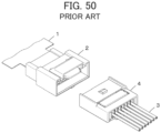
- JP 2007-214087 A discloses a connector as shown in FIG. 50 .
- the connector includes a first connector 2 connected to an end of a sheet type conductive member 1, and a second connector 4 attached to a tip end of an electric wire 3, and the second connector 4 is fitted with the first connector 2, whereby the electric wire 3 can be connected to a flexible conductor of the sheet type conductive member 1.
- the device Since, however, the first connector 2 and the second connector 4 to be fitted with each other are required for connecting the electric wire 3 to the flexible conductor of the sheet type conductive member 1, the device is enlarged, while the electric connection is less reliable due to presence of a disconnectable connection site between the first connector 2 and the second connector 4.
- the present invention has been made to solve the conventional problem as above and aims at providing a connector that can connect a conductor portion of an electric wire to a flexible conductor of a sheet type conductive member with high reliability while its size can be reduced.
- the connector according to the present invention is a connector for connecting a conductor portion of an electric wire to a flexible conductor exposed on at least one surface of a sheet type conductive member, the connector comprising:
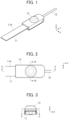
- FIGS. 1 to 4 show a connector according to Embodiment 1.
- the connector is configured such that a covered electric wire 12 is connected to a sheet type conductive member 11, and the connector includes a housing 13 formed of an insulating resin material.
- the sheet type conductive member 11 has a top surface and a bottom surface facing in opposite directions from each other and has a flexible conductor 11A exposed at least on the top surface.
- conductive cloth woven using a conductive thread such as silver can be used, for example.
- the flexible conductor 11A is exposed not only on the top surface but also on the bottom surface of the sheet type conductive member 11.
- one obtained by applying a conductive ink on a surface of cloth having no conductivity by printing or another method to form the flexible conductor 11A on the surface thereof can also be used as the sheet type conductive member 11.
- a member obtained by forming the flexible conductor 11A formed of a conductive pattern on a surface of an insulating sheet body of a resin film or the like may be used as the sheet type conductive member 11.
- the sheet type conductive member 11 has a band shape extending in a predetermined direction.
- the covered electric wire 12 has such a structure that an outer periphery of a conductor portion described later is covered with an insulating cover portion. With the connector according to Embodiment 1, the conductor portion of the covered electric wire 12 is electrically connected to the flexible conductor 11A of the sheet type conductive member 11.
- the covered electric wire 12 extends in the same direction as the direction in which the sheet type conductive member 11 of band shape extends.
- the predetermined direction in which the sheet type conductive member 11 extends toward the housing 13 is called “+Y direction,” the width direction of the sheet type conductive member 11 of band shape “X direction,” and the direction orthogonal to an XY plane “Z direction.”
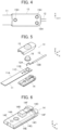
- FIG. 5 shows an exploded perspective view of the connector.
- the connector includes a first insulator 14 and a second insulator 15, and these first and second insulators 14 and 15 constitute the housing 13.
- the sheet type conductive member 11 is disposed on the +Z direction side of the first insulator 14, and a conductor portion 12A exposed from an insulating cover portion 12B of the covered electric wire 12 is disposed on the +Z direction side of the sheet type conductive member 11.
- the conductor portion 12A of the covered electric wire 12 may be either of a so-called single line that is formed of one conductor line and a so-called strand that is formed by twisting a plurality of conductors.
- the connector includes a contact force-securing member 16.
- the contact force-securing member 16 is disposed on the +Z direction side of the conductor portion 12A of the covered electric wire 12, and the second insulator 15 is disposed on the +Z direction side of the contact force-securing member 16.
- the first insulator 14 includes a flat plate portion 14A of substantially rectangular shape extending along an XY plane, and a protrusion portion 14B of substantially prismatic shape protruding in the +Z direction is formed on the +Z directional surface (first retaining surface) of the flat plate portion 14A.
- an insertion groove 14C is formed to extend in the +Y direction from the protrusion portion 14B, and at the +Y directional end of the insertion groove 14C, an insertion groove 14D is formed with a larger groove width than that of the insertion groove 14C.
- a projection housing portion 14E of recess shape is formed to be recessed in the -Z direction.
- the flat plate portion 14A includes three through-holes 14F separately formed on opposite sides of the insertion groove 14C in the X direction and on the -Y direction side of the projection housing portion 14E, the through-holes 14F penetrating the flat plate portion 14A in the Z direction.
- step portions 14G are separately formed to extend in the Y direction.
- the second insulator 15 includes a flat plate portion 15A of substantially rectangular shape extending along an XY plane, and a dome-shaped portion 15B protruding in the +Z direction from the flat plate portion 15A.
- a recess portion 15C is formed to extend from the -Z directional surface (second retaining surface) of the flat plate portion 15A to an inside of the dome-shaped portion 15B and open toward the -Z direction.
- an insertion groove 15D is formed to extend in the +Y direction from the recess portion 15C, and at the +Y directional end of the insertion groove 15D, an insertion groove 15E is formed with a larger groove width than that of the insertion groove 15D.
- a projection 15F is formed to protrude in the -Z direction, and a slit 15G is formed in the projection 15F to extend in the Y direction so as to divide the projection 15F in two in the X direction.
- the slit 15G is to serve as a tip retaining portion for retaining a tip of the conductor portion 12A of the covered electric wire 12 and has a slit width that is slightly smaller than the diameter of the conductor portion 12A.
- the flat plate portion 15A includes three bosses 15H separately formed on opposite sides of the insertion groove 15D in the X direction and on the -Y direction side of the projection 15F, the bosses 15H protruding in the -Z direction.
- lateral plates 15J are separately formed to protrude in the -Z direction and extend in the Y direction.
- the insertion groove 14C of the first insulator 14 and the insertion groove 15D of the second insulator 15 work together to retain the conductor portion 12A of the covered electric wire 12
- the insertion groove 14D of the first insulator 14 and the insertion groove 15E of the second insulator 15 work together to retain the insulating cover portion 12B of the covered electric wire 12 so as to constitute an insulating cover retaining portion.
- the sheet type conductive member 11 is provided with through-holes 11B and 11C respectively corresponding to the projection 15F of the second insulator 15 and the boss 15H on the -Y direction side of the second insulator 15.
- the contact force-securing member 16 is formed of a metal material and has a cylindrical shape as shown in FIG. 8 .
- the contact force-securing member 16 is, as shown in FIG. 9 , disposed at an outside of the conductor portion 12A of the covered electric wire 12 and the flexible conductor 11A of the sheet type conductive member 11, the conductor portion 12A and the flexible conductor 11A contacting each other, in the recess portion 15C of the second insulator 15, and secures the contact force between the conductor portion 12A and the flexible conductor 11A.
- the contact force-securing member 16 is first inserted in the recess portion 15C of the second insulator 15 from the -Z direction, and the tip of the conductor portion 12A exposed as a result of removal of a portion of the insulating cover portion 12B at the -Y directional end of the covered electric wire 12 is press-fitted in the slit 15G formed as the tip retaining portion in the projection 15F of the second insulator 15, thereby being temporarily retained in the slit 15G.
- the first insulator 14 is pressed toward the second insulator 15 relatively in the +Z direction with the sheet type conductive member 11 being held therebetween. Accordingly, the sheet type conductive member 11 and the conductor portion 12A of the covered electric wire 12 are held between the +Z directional surface (first retaining surface) of the first insulator 14 and the -Z directional surface (second retaining surface) of the second insulator 15.
- the sheet type conductive member 11 and the conductor portion 12A of the covered electric wire 12 are pressed and inserted in an inside of the contact force-securing member 16 disposed in the recess portion 15C of the second insulator 15.
- the boss 15H positioned on the -Y direction side among the three bosses 15H penetrates the corresponding through-hole 14F of the first insulator 14 via the through-hole 11C of the sheet type conductive member 11 shown in FIG. 5 .
- tips of the three bosses 15H projecting on the -Z direction side of the first insulator 14 are then thermally deformed, whereby the first insulator 14 and the second insulator 15 are fixed to each other.
- the assembling operation of the connector is completed.
- the protrusion portion 14B of the first insulator 14 is inserted in the inside of the contact force-securing member 16 while pressing the sheet type conductive member 11 and the conductor portion 12A of the covered electric wire 12 therein, whereby, as shown in FIGS. 9 and 10 , the sheet type conductive member 11 deforms to conform to a surface of the protrusion portion 14B, and the conductor member 12A of the covered electric wire 12 is held between a surface of the sheet type conductive member 11 and an inner surface of the contact force-securing member 16 to be bent to conform to the surface of the deformed sheet type conductive member 11.
- the protrusion portion 14B has a substantially prismatic shape as shown in FIG. 11 , the sheet type conductive member 11 deformed to conform to the surface of the protrusion portion 14B and the conductor portion 12A of the covered electric wire 12 are held between the +Y and -Y directional lateral surfaces of the protrusion portion 14B and the inner surface of the contact force-securing member 16 of cylindrical shape, and the conductor portion 12A of the covered electric wire 12 contacts the flexible conductor 11A exposed on the top surface of the sheet type conductive member 11 at a predetermined contact force and is electrically connected to the flexible conductor 11A.
- the conductor portion 12A of the covered electric wire 12 bends to conform to the surface of the deformed sheet type conductive member 11, whereby the tip of the conductor portion 12A temporarily retained in the slit 15G of the projection 15F of the second insulator 15 is pulled out from the slit 15G as shown in FIG. 9 .
- the projection 15F of the second insulator 15 penetrates the through-hole 11B of the sheet type conductive member 11 and is housed in the projection housing portion 14E of the first insulator 14, and the conductor portion 12A of the covered electric wire 12 is retained by the insertion groove 14C of the first insulator 14 and the insertion groove 15D of the second insulator 15, while the insulating cover portion 12B of the covered electric wire 12 is retained by the insertion groove 14D of the first insulator 14 and the insertion groove 15E of the second insulator 15.
- the pair of lateral plates 15J of the second insulator 15 are fitted in the pair of step portions 14G of the first insulator 14.
- the protrusion portion 14B of the first insulator 14 is inserted in the inside of the contact force-securing member 16 that is inserted in the recess portion 15C of the second insulator 15 while pressing the sheet type conductive member 11 and the conductor portion 12A of the covered electric wire 12 therein, whereby the flexible conductor 11A exposed at the top surface of the sheet type conductive member 11 is electrically connected to the conductor portion 12A of the covered electric wire 12.
- the connector can reduce the size thereof while improving reliability of the electric connection between the flexible conductor 11A and the conductor portion 12A.
- the connector of Embodiment 1 When the connector of Embodiment 1 is applied to a smart cloth, and an electrode (not shown) is connected to the flexible conductor 11A of the sheet type conductive member 11, the electrode disposed at a measurement position and a wearable device can be connected to each other by means of the inexpensive covered electric wire 12 with low electric resistance.
- the slit 15G formed in the projection 15F of the second insulator 15 constitutes the tip retaining portion for retaining the tip of the conductor portion 12A of the covered electric wire 12, the tip retaining portion may be formed in the first insulator 14.
- the three bosses 15H of the second insulator 15 penetrate the three through-holes 14F of the first insulator 14, it is possible to configure the connector in which, conversely, a plurality of bosses 15H formed in the first insulator 14 penetrate a plurality of through-holes formed in the second insulator 15.
- FIGS. 12 to 14 show a connector according to Embodiment 2.
- this connector is configured such that the covered electric wire 12 is connected to the sheet type conductive member 11, and the connector includes a housing 23 formed of an insulating resin material.
- the sheet type conductive member 11 and the covered electric wire 12 are the same as those used in Embodiment 1.
- FIG. 15 shows an exploded perspective view of the connector according to Embodiment 2.
- the connector includes a first insulator 24 and a second insulator 25, and these first and second insulators 24 and 25 constitute the housing 23.
- the sheet type conductive member 11 is disposed on the +Z direction side of the first insulator 24, a relay member 26 is disposed on the +Z direction side of the sheet type conductive member 11, and the conductor portion 12A exposed from the insulating cover portion 12B of the covered electric wire 12 is disposed on the +Z direction side of the relay member 26.
- the second insulator 25 is disposed on the +Z direction side of the conductor portion 12A of the covered electric wire 12.
- the first insulator 24 includes a flat plate portion 24A of substantially rectangular shape extending along an XY plane, and a protrusion portion 24B of substantially prismatic shape protruding in the +Z direction is formed on the +Z directional surface (first retaining surface) of the flat plate portion 24A.
- the flat plate portion 24A is provided with a pair of through-holes 24C spaced apart from each other in the X direction on the +Y direction side of the protrusion portion 24B and a pair of through-holes 24D also spaced apart from each other in the X direction on the -Y direction side of the protrusion portion 24B.
- an insertion groove 24E is formed to extend in the +Y direction between the pair of through-holes 24C, and at the +Y directional end of the insertion groove 24E, an insertion groove 24F is formed with a larger groove width than that of the insertion groove 24E.
- jutting portions 24G are separately formed to protrude in the +Z direction and extend in the Y direction.
- the second insulator 25 includes a flat plate portion 25A of substantially rectangular shape extending along an XY plane, and a recess portion 25B is formed at the middle in the Y direction of the flat plate portion 25A and recessed in the +Z direction from the -Z directional surface (second retaining surface) of the flat plate portion 25A.
- a sheet type conductive member housing portion 25C of recess shape is formed for housing the +Y directional end of the sheet type conductive member 11.
- the sheet type conductive member housing portion 25C extends from the +Y direction side of the recess portion 25B to the -Y directional end of the flat plate portion 25A.
- an insertion groove 25D is formed to extend in the +Y direction and the -Y direction from the recess portion 25B, and at the +Y directional end of the insertion groove 25D extending in the +Y direction from the recess portion 25B, an insertion groove 25E is formed with a larger groove width than that of the insertion groove 25D.
- the flat plate portion 25A includes two bosses 25F separately formed on the +Y direction side and the -Y direction side of the recess portion 25B, the bosses 25F protruding in the -Z direction.
- a slit 25G is formed to extend in the Y direction so as to divide the relevant boss 25F in two in the X direction.
- the slits 25G are connected to the insertion groove 25D.
- step portions 25H are separately formed to extend in the Y direction.
- the relay member 26 is formed of a conductive metal material and includes a tubular portion 26A of cylindrical shape as shown in FIG. 18 .
- the relay member 26 is disposed between the conductor portion 12A of the covered electric wire 12 and the flexible conductor 11A of the sheet type conductive member 11 in the recess portion 25B of the second insulator 25, and is used to electrically connect the conductor portion 12A to the flexible conductor 11A.
- the conductor portion 12A of the covered electric wire 12 is first inserted in the slits 25G of the two bosses 25F of the second insulator 25 from the -Z direction, and in this state, the first insulator 24 is pressed toward the second insulator 25 relatively in the +Z direction with the relay member 26 and the sheet type conductive member 11 being held therebetween. Accordingly, the sheet type conductive member 11 and the conductor portion 12A of the covered electric wire 12 are held between the +Z directional surface (first retaining surface) of the first insulator 24 and the -Z directional surface (second retaining surface) of the second insulator 25.
- the sheet type conductive member 11, the relay member 26, and the conductor portion 12A are pressed in the recess portion 25B of the second insulator 25.
- the two bosses 25F of the second insulator 25 penetrate the through-holes 24C and 24D of the first insulator 24.
- the boss 25F positioned on the +Y direction side penetrates the through-hole 24C that is divided in two by the slit 25G
- the boss 25F positioned on the -Y direction side penetrates the through-hole 24D that is divided in two by the slit 25G.
- tips of the two bosses 25F protruding on the -Z direction side of the first insulator 24 are then thermally deformed, whereby the first insulator 24 and the second insulator 25 are fixed to each other.
- the assembling operation of the connector is completed.
- the protrusion portion 24B of the first insulator 24 presses the sheet type conductive member 11, the relay member 26, and the conductor portion 12A into the recess portion 25B of the second insulator 25, whereby, as shown in FIGS. 19 and 20 , the sheet type conductive member 11 deforms to conform to a surface of the protrusion portion 24B and is held between an outer surface of the protrusion portion 24B and an inner surface of the tubular portion 26A of the relay member 26.
- the conductor portion 12A of the covered electric wire 12 is held between an outer surface of the tubular portion 26A of the relay member 26 and an inner surface of the recess portion 25B of the second insulator 25.
- the conductor portion 12A of the covered electric wire 12 is electrically connected to the flexible conductor 11A exposed on the top surface of the sheet type conductive member 11 via the relay member 26.
- the sheet type conductive member 11 is housed in the sheet type conductive member housing portion 25C of the second insulator 25, the conductor portion 12A of the covered electric wire 12 is retained in the insertion groove 24E of the first insulator 24 and the insertion groove 25D of the second insulator 25, and the insulating cover portion 12B of the covered electric wire 12 is retained in the insertion groove 24F of the first insulator 24 and the insertion groove 25E of the second insulator 25.
- the pair of jutting portions 24G of the first insulator 24 are fitted in the pair of step portions 25H of the second insulator 25.
- the connector according to Embodiment 2 can also reduce the size thereof while improving reliability of the electric connection between the flexible conductor 11A and the conductor portion 12A.
- the conductor portion 12A of the covered electric wire 12 is electrically connected to the flexible conductor 11A of the sheet type conductive member 11 via the relay member 26 in Embodiment 2 described above, the conductor portion 12A of the covered electric wire 12 can be brought into direct contact with and electrically connected to the flexible conductor 11A of the sheet type conductive member 11 without having the relay member 26 therebetween, similarly to Embodiment 1.
- FIGS. 21 to 23 show a connector according to Embodiment 3. As with the connectors according to Embodiments 1 and 2, this connector is configured such that the covered electric wire 12 is connected to the sheet type conductive member 11, and the connector includes a housing 33 formed of an insulating resin material.
- the sheet type conductive member 11 and the covered electric wire 12 are the same as those used in Embodiments 1 and 2.
- FIG. 24 shows an exploded perspective view of the connector according to Embodiment 3.
- the connector includes the first insulator 24 used in Embodiment 2 and a second insulator 35, and these first and second insulators 24 and 35 constitute the housing 33.
- the sheet type conductive member 11 is disposed on the +Z direction side of the first insulator 24, the conductor portion 12A of the covered electric wire 12 is disposed on the +Z direction side of the sheet type conductive member 11, and the second insulator 35 is disposed on the +Z direction side of the conductor portion 12A.
- the second insulator 35 includes a flat plate portion 35A in which a recess portion 35B is formed.
- the flat plate portion 35A includes the sheet type conductive member housing portion 25C of recess shape, the insertion grooves 25D and 25E, the two bosses 25F each having the slit 25G, and the pair of step portions 25H.
- the conductor portion 12A of the covered electric wire 12 is first inserted in the slits 25G of the two bosses 25F of the second insulator 35 from the -Z direction, and in this state, the first insulator 24 is pressed toward the second insulator 35 relatively in the +Z direction with the sheet type conductive member 11 being held therebetween. Accordingly, the sheet type conductive member 11 and the conductor portion 12A of the covered electric wire 12 are held between the +Z directional surface (first retaining surface) of the first insulator 24 and the -Z directional surface (second retaining surface) of the second insulator 35.
- the sheet type conductive member 11 and the conductor portion 12A are pressed in the recess portion 35B of the second insulator 35.
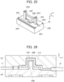
- the protrusion portion 24B of the first insulator 24 presses the sheet type conductive member 11 and the conductor portion 12A into the recess portion 35B of the second insulator 35, whereby, as shown in FIGS. 26 and 27 , the sheet type conductive member 11 and the conductor portion 12A deform to conform to a surface of the protrusion portion 24B and are held between an outer surface of the protrusion portion 24B and an inner surface of the recess portion 35B of the second insulator 35.
- the conductor portion 12A of the covered electric wire 12 is brought into direct contact with and electrically connected to the flexible conductor 11A exposed on the top surface of the sheet type conductive member 11.
- the connector according to Embodiment 3 can also reduce the size thereof while improving reliability of the electric connection between the flexible conductor 11A and the conductor portion 12A.
- the conductor portion 12A of the covered electric wire 12 can be electrically connected to the flexible conductor 11A of the sheet type conductive member 11 via the relay member 26.
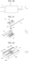
- FIGS. 28 to 30 show a connector according to Embodiment 4. As with the connectors according to Embodiments 1 to 3, this connector is configured such that the covered electric wire 12 is connected to the sheet type conductive member 11, and the connector includes a housing 43 formed of an insulating resin material.
- the sheet type conductive member 11 and the covered electric wire 12 are the same as those used in Embodiments 1 to 3.
- FIG. 31 shows an exploded perspective view of the connector according to Embodiment 4.
- the connector includes a first insulator 44 and a second insulator 45, and these first and second insulators 44 and 45 constitute the housing 43.
- the conductor portion 12A exposed from the insulating cover portion 12B of the covered electric wire 12 is disposed on the -Z direction side of the first insulator 44, the relay member 26 used in Embodiment 2 is disposed on the -Z direction side of the conductor portion 12A, and the sheet type conductive member 11 is disposed on the -Z direction side of the relay member 26.
- the second insulator 45 is disposed on the -Z direction side of the sheet type conductive member 11.
- the first insulator 44 includes a flat plate portion 44A of substantially rectangular shape, and a protrusion portion 44B of substantially circular cylindrical shape is formed on the flat plate portion 44A to protrude in the -Z direction.
- a protrusion portion 44B of substantially circular cylindrical shape is formed on the flat plate portion 44A to protrude in the -Z direction.
- an intermediate retaining portion 44C of groove shape is formed to extend across the protrusion portion 44B in the Y direction.
- the intermediate retaining portion 44C is used to retain an intermediate part of the conductor portion 12A of the covered electric wire 12.
- the flat plate portion 44A includes the pair of through-holes 24D formed on the +Y direction side of the protrusion portion 44B and spaced apart from each other in the X direction, the insertion groove 24E formed to extend in the Y direction between the pair of through-holes 24D, the insertion groove 24F formed at the +Y directional end of the insertion groove 24E with a larger groove width than that of the insertion groove 24E, and the jutting portions 24G separately formed at the X-directional opposite lateral ends of the flat plate portion 44A and protruding in the -Z direction.
- the flat plate portion 44A is provided with a through-hole 44H on the -Y direction side of the protrusion portion 44B, the through-hole 44H penetrating the flat plate portion 44A in the Z direction.
- the second insulator 45 includes a flat plate portion 45A in which a recess portion 45B is formed.
- the flat plate portion 45A includes the sheet type conductive member housing portion 25C of recess shape, the insertion grooves 25D and 25E, the boss 25F formed on the +Y direction side of the recess portion 45B and having the slit 25G, and the pair of step portions 25H.
- the flat plate portion 45A is provided with a boss 45J of circular cylindrical shape on the -Y direction side of the recess portion 45B, the boss 45J protruding in the +Z direction.
- an intermediate part of the conductor portion 12A of the covered electric wire 12 is inserted in the intermediate retaining portion 44C of the protrusion portion 44B of the first insulator 44 from the -Z direction, and in this state, the first insulator 44 is pressed toward the second insulator 45 relatively in the +Z direction with the relay member 26 and the sheet type conductive member 11 being held therebetween. Accordingly, the sheet type conductive member 11 and the conductor portion 12A of the covered electric wire 12 are held between the -Z directional surface (first retaining surface) of the first insulator 44 and the +Z directional surface (second retaining surface) of the second insulator 45.
- the conductor portion 12A, the relay member 26, and the sheet type conductive member 11 are pressed in the recess portion 45B of the second insulator 45.
- the protrusion portion 44B of the first insulator 44 presses the conductor portion 12A, the relay member 26, and the sheet type conductive member 11 into the recess portion 45B of the second insulator 45, whereby, as shown in FIGS. 34 and 35 , the conductor portion 12A of the covered electric wire 12 deforms to conform to a surface of the protrusion portion 44B and is held between an outer surface of the protrusion portion 44B and an inner surface of the tubular portion 26A of the relay member 26.
- the sheet type conductive member 11 is held between an outer surface of the tubular portion 26A of the relay member 26 and an inner surface of the recess portion 45B of the second insulator 45.
- the conductor portion 12A of the covered electric wire 12 is electrically connected to the flexible conductor 11A exposed on the top surface of the sheet type conductive member 11 via the relay member 26.
- the connector according to Embodiment 4 can also reduce the size thereof while improving reliability of the electric connection between the flexible conductor 11A and the conductor portion 12A.
- FIGS. 36 and 37 show a connector according to Embodiment 5.
- this connector is configured such that the covered electric wire 12 is connected to the sheet type conductive member 11, and the connector includes a housing 53 formed of an insulating resin material.
- the sheet type conductive member 11 and the covered electric wire 12 are the same as those used in Embodiments 1 to 4.
- the conductor portion 12A of the covered electric wire 12 is brought in direct contact with and thus electrically connected to the flexible conductor 11A of the sheet type conductive member 11.
- FIG. 38 shows an exploded perspective view of the connector according to Embodiment 5.
- the connector includes a first insulator 54 and a second insulator 55, and these first and second insulators 54 and 55 constitute the housing 53.
- the conductor portion 12A of the covered electric wire 12 is disposed on the +Z direction side of the first insulator 54, the sheet type conductive member 11 is disposed on the +Z direction side of the conductor portion 12A of the covered electric wire 12, and the second insulator 55 is disposed on the +Z direction side of the sheet type conductive member 11.
- the first insulator 54 includes a flat plate portion 54A extending along an XY plane, and a protrusion portion 54B of substantially circular cylindrical shape protruding in the +Z direction is formed on the +Z directional surface (first retaining surface) of the flat plate portion 54A.
- a protrusion portion 54B of substantially circular cylindrical shape protruding in the +Z direction is formed on the +Z directional surface (first retaining surface) of the flat plate portion 54A.
- an intermediate retaining portion 54C of groove shape is formed to extend across the protrusion portion 54B in the Y direction.
- the intermediate retaining portion 54C is used to retain an intermediate part of the conductor portion 12A of the covered electric wire 12 and extends not only on the upper surface of the protrusion portion 54B but also on lateral surfaces of the protrusion portion 54B.
- an insertion groove 54D is formed on the +Y direction side of the protrusion portion 54B, the insertion groove 54D extending in the Y direction and having a larger groove width than that of the intermediate retaining portion 54C.
- a peripheral wall 54E is formed to protrude in the +Z direction.
- a cutout is provided to the peripheral wall 54E to form a sheet type conductive member lead-out portion 54F
- a cutout is provided to the peripheral wall 54E to form a covered electric wire lead-out portion 54G connected to the insertion groove 54D.
- the second insulator 55 includes a flat plate portion 55A extending along an XY plane, and a recess portion 55B is formed at the middle of the -Z directional surface (second retaining surface) of the flat plate portion 55A and recessed in the +Z direction.
- an insertion groove 55C is formed to extend in the Y direction from the +Y direction side of the recess portion 55B to the +Y directional end of the flat plate portion 55A, and at the +Y directional end of the flat plate portion 55A, a projection 55D is formed to be connected to the insertion groove 55C.
- the insertion groove 55C has the same groove width as that of the insertion groove 54D of the first insulator 54, and the projection 55D has a width corresponding to the covered electric wire lead-out portion 54G of the first insulator 54.
- a step portion 55E is formed at a peripheral edge portion of the flat plate portion 55A.
- an intermediate part of the conductor portion 12A of the covered electric wire 12 is inserted in the intermediate retaining portion 54C of the protrusion portion 54B of the first insulator 54 from the +Z direction, and in this state, the first insulator 54 is pressed toward the second insulator 55 relatively in the +Z direction with the sheet type conductive member 11 being held therebetween. Accordingly, the sheet type conductive member 11 and the conductor portion 12A of the covered electric wire 12 are held between the +Z directional surface (first retaining surface) of the first insulator 54 and the -Z directional surface (second retaining surface) of the second insulator 55.
- the conductor portion 12A and the sheet type conductive member 11 are pressed in the recess portion 55B of the second insulator 55.
- the sheet type conductive member 11 is led out through the sheet type conductive member lead-out portion 54F of the first insulator 54, and the covered electric wire 12 is led out through the covered electric wire lead-out portion 54G of the first insulator 54.
- the peripheral wall 54E of the first insulator 54 is fitted in the step portion 55E of the second insulator 55.
- the peripheral wall 54E of the first insulator 54 is adhered to the step portion 55E of the second insulator 55, whereby the assembling operation of the connector is completed.
- the protrusion portion 54B of the first insulator 54 presses the sheet type conductive member 11 and the conductor portion 12A into the recess portion 55B of the second insulator 55, whereby, as shown in FIGS. 41 and 42 , the sheet type conductive member 11 and the conductor portion 12A deform to conform to a surface of the protrusion portion 54B and are held between an outer surface of the protrusion portion 54B and an inner surface of the recess portion 55B of the second insulator 55.
- the conductor portion 12A of the covered electric wire 12 is brought into direct contact with and electrically connected to the flexible conductor 11A exposed on the top surface of the sheet type conductive member 11.
- the connector according to Embodiment 5 can also reduce the size thereof while improving reliability of the electric connection between the flexible conductor 11A and the conductor portion 12A.
- FIGS. 43 and 44 show a connector according to Embodiment 6.
- This connector is configured such that in the connector according to Embodiment 5, the contact force-securing member is used to secure the contact force between the conductor portion 12A of the covered electric wire 12 and the flexible conductor 11A of the sheet type conductive member 11, similarly to Embodiment 1.
- the connector includes a housing 63 formed of an insulating resin material.
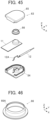
- FIG. 45 shows an exploded perspective view of the connector according to Embodiment 6.
- the connector includes the first insulator 54 used in Embodiment 5 and a second insulator 65, and these first and second insulators 54 and 65 constitute the housing 63.
- the conductor portion 12A of the covered electric wire 12 is disposed on the +Z direction side of the first insulator 54, the sheet type conductive member 11 is disposed on the +Z direction side of the conductor portion 12A of the covered electric wire 12, and a contact force-securing member 66 is disposed on the +Z direction side of the sheet type conductive member 11.
- the second insulator 65 is disposed on the +Z direction side of the contact force-securing member 66.
- the contact force-securing member 66 is formed of a metal material and includes a tubular portion 66A of cylindrical shape as shown in FIG. 46 .
- the second insulator 65 includes a flat plate portion 65A extending along an XY plane, and a recess portion 65B is formed at the middle of the -Z directional surface (second retaining surface) of the flat plate portion 65A and recessed in the +Z direction.
- the recess portion 65B has a larger diameter than that of the recess portion 55B of the second insulator 55 in Embodiment 5 and is sized so that the tubular portion 66A of the contact force-securing member 66 can be housed therein.
- the flat plate portion 65A is provided with the insertion groove 55C, the projection 55D, and the step portion 55E.
- an intermediate part of the conductor portion 12A of the covered electric wire 12 is inserted in the intermediate retaining portion 54C of the protrusion portion 54B of the first insulator 54 from the +Z direction, while the contact force-securing member 66 is inserted in the recess portion 65B of the second insulator 65 from the -Z direction, and in this state, the first insulator 54 is pressed toward the second insulator 65 relatively in the +Z direction with the sheet type conductive member 11 being held therebetween.
- the sheet type conductive member 11 and the conductor portion 12A of the covered electric wire 12 are held between the +Z directional surface (first retaining surface) of the first insulator 54 and the -Z directional surface (second retaining surface) of the second insulator 65.
- the conductor portion 12A of the covered electric wire 12 and the sheet type conductive member 11 are pressed and inserted in an inside of the contact force-securing member 66 disposed in the recess portion 65B of the second insulator 65.
- the peripheral wall 54E of the first insulator 54 is fitted in the step portion 55E of the second insulator 65.
- the peripheral wall 54E of the first insulator 54 is adhered to the step portion 55E of the second insulator 65, whereby the assembling operation of the connector is completed.
- the protrusion portion 54B of the first insulator 54 is inserted in the inside of the contact force-securing member 66 while pressing the sheet type conductive member 11 and the conductor portion 12A of the covered electric wire 12 therein, whereby, as shown in FIGS. 48 and 49 , the sheet type conductive member 11 and the conductor portion 12A deform to conform to a surface of the protrusion portion 54B and are held between an outer surface of the protrusion portion 54B and an inner surface of the contact force-securing member 66.
- the conductor portion 12A of the covered electric wire 12 is brought into contact with the flexible conductor 11A exposed on the top surface of the sheet type conductive member 11 at a predetermined contact force and is electrically connected to the flexible conductor 11A.
- the connector according to Embodiment 6 can also reduce the size thereof while improving reliability of the electric connection between the flexible conductor 11A and the conductor portion 12A.
- the covered electric wire 12 is used as an electric wire to be connected to the sheet type conductive member 11 in Embodiments 1 to 6 above, an electric wire formed of only the conductor portion 12A whose outer periphery is not covered with the insulating cover portion 12B made of an insulating material may also be connected to the sheet type conductive member 11.
- one protrusion portion 14B, 24B, 44B, 54B formed on the first insulator 14, 24, 44, 54 is housed in one recess portion 15C, 25B, 35B, 45B, 55B, 65B formed in the second insulator 15, 25, 35, 45, 55, 65 to thereby connect the conductor portion 12A of one covered electric wire 12 to the flexible conductor 11A of one sheet type conductive member 11, but the connector can be configured such that, using the first insulator having a plurality of protrusion portions and the second insulator having a plurality of recess portions, conductor portions of a plurality of electric wires are connected to flexible conductors of a plurality of sheet type conductive members in a similar manner.
Landscapes
- Coupling Device And Connection With Printed Circuit (AREA)
Abstract
Description
- The present invention relates to a connector, particularly to a connector for connecting a conductor portion of an electric wire to a flexible conductor of a sheet type conductive member.
- In recent years, attention has been drawn to so-called smart clothes that can obtain user's biological data such as the heart rate and the body temperature only by being worn by the user. Such a smart cloth is equipped with an electrode disposed at a measurement position and formed of a flexible conductor, and when a wearable device serving as a measurement device is electrically connected to the electrode, it is possible to send biological data to the wearable device.
- Connection between the electrode and the wearable device can be established by using, for example, a connector to be connected to the flexible conductor.
- Meanwhile, in a case where the wearable device is disposed apart from a measurement position, it is necessary to constitute an electrical path from the electrode disposed at the measurement position to an attachment position of the connector, and when such an electrical path is formed of the flexible conductor, electric resistance becomes high, and cost increases.
- To cope with it, in order to connect an electrode formed of a flexible conductor to a wearable device by an inexpensive electric wire with low electric resistance, the development of a small-sized connector for connecting an electric wire to a flexible conductor disposed on a garment is desired.
- As a connector for connecting an electric wire to a flexible conductor, for instance,
JP 2007-214087 A FIG. 50 . The connector includes afirst connector 2 connected to an end of a sheet typeconductive member 1, and asecond connector 4 attached to a tip end of anelectric wire 3, and thesecond connector 4 is fitted with thefirst connector 2, whereby theelectric wire 3 can be connected to a flexible conductor of the sheet typeconductive member 1. - Since, however, the
first connector 2 and thesecond connector 4 to be fitted with each other are required for connecting theelectric wire 3 to the flexible conductor of the sheet typeconductive member 1, the device is enlarged, while the electric connection is less reliable due to presence of a disconnectable connection site between thefirst connector 2 and thesecond connector 4. - The present invention has been made to solve the conventional problem as above and aims at providing a connector that can connect a conductor portion of an electric wire to a flexible conductor of a sheet type conductive member with high reliability while its size can be reduced.
- The connector according to the present invention is a connector for connecting a conductor portion of an electric wire to a flexible conductor exposed on at least one surface of a sheet type conductive member, the connector comprising:
- a first insulator including a first retaining surface and a protrusion portion formed on and protruding from the first retaining surface, and
- a second insulator including a second retaining surface opposed to the first retaining surface and a recess portion formed in the second retaining surface and corresponding to the protrusion portion,
- wherein the first insulator and the second insulator are connected to each other with the sheet type conductive member and the electric wire being held between the first retaining surface and the second retaining surface, and
- at least part of the protrusion portion is housed in the recess portion, whereby the conductor portion of the electric wire is electrically connected to the flexible conductor of the sheet type conductive member in the recess portion.
-
-
FIG. 1 is a perspective view showing a connector according toEmbodiment 1. -
FIG. 2 is a plan view showing the connector according toEmbodiment 1. -
FIG. 3 is a front view showing the connector according toEmbodiment 1. -
FIG. 4 is a bottom view showing the connector according toEmbodiment 1. -
FIG. 5 is an exploded perspective view of the connector according toEmbodiment 1. -
FIG. 6 is a perspective view showing a first insulator used in the connector according toEmbodiment 1. -
FIG. 7 is a perspective view showing a second insulator used in the connector according toEmbodiment 1 when viewed from an obliquely lower position. -
FIG. 8 is a perspective view showing a contact force-securing member used in the connector according toEmbodiment 1. -
FIG. 9 is a cross-sectional view taken along line A-A inFIG. 2 . -
FIG. 10 is a cross-sectional view taken along line B-B inFIG. 2 . -
FIG. 11 is a cross-sectional view taken along line C-C inFIG. 3 . -
FIG. 12 is a perspective view showing a connector according toEmbodiment 2. -
FIG. 13 is a plan view showing the connector according toEmbodiment 2. -
FIG. 14 is a bottom view showing the connector according toEmbodiment 2. -
FIG. 15 is an exploded perspective view of the connector according toEmbodiment 2. -
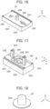
FIG. 16 is a perspective view showing a first insulator used in the connector according toEmbodiment 2. -
FIG. 17 is a perspective view showing a second insulator used in the connector according toEmbodiment 2 when viewed from an obliquely lower position. -
FIG. 18 is a perspective view showing a relay member used in the connector according toEmbodiment 2. -
FIG. 19 is a cross-sectional view taken along line D-D inFIG. 13 . -
FIG. 20 is a cross-sectional view taken along line E-E inFIG. 13 . -
FIG. 21 is a perspective view showing a connector according toEmbodiment 3. -
FIG. 22 is a plan view showing the connector according to Embodiment 3. -
FIG. 23 is a bottom view showing the connector according to Embodiment 3. -
FIG. 24 is an exploded perspective view of the connector according toEmbodiment 3. -
FIG. 25 is a perspective view showing a second insulator used in the connector according toEmbodiment 3 when viewed from an obliquely lower position. -
FIG. 26 is a cross-sectional view taken along line F-F inFIG. 22 . -
FIG. 27 is a cross-sectional view taken along line G-G inFIG. 22 . -
FIG. 28 is a perspective view showing a connector according toEmbodiment 4. -
FIG. 29 is a plan view showing the connector according to Embodiment 4. -
FIG. 30 is a bottom view showing the connector according to Embodiment 4. -
FIG. 31 is an exploded perspective view of the connector according toEmbodiment 4. -
FIG. 32 is a perspective view showing a first insulator used in the connector according toEmbodiment 4. -
FIG. 33 is a perspective view showing a second insulator used in the connector according toEmbodiment 4 when viewed from an obliquely lower position. -
FIG. 34 is a cross-sectional view taken along line H-H inFIG. 29 . -
FIG. 35 is a cross-sectional view taken along line J-J inFIG. 29 . -
FIG. 36 is a perspective view showing a connector according to Embodiment 5. -
FIG. 37 is a plan view showing the connector according to Embodiment 5. -
FIG. 38 is an exploded perspective view of the connector according to Embodiment 5. -
FIG. 39 is a perspective view showing a first insulator used in the connector according to Embodiment 5. -
FIG. 40 is a perspective view showing a second insulator used in the connector according to Embodiment 5 when viewed from an obliquely lower position. -
FIG. 41 is a cross-sectional view taken along line K-K inFIG. 37 . -
FIG. 42 is a cross-sectional view taken along line L-L inFIG. 37 . -
FIG. 43 is a perspective view showing a connector according to Embodiment 6. -
FIG. 44 is a plan view showing the connector according to Embodiment 6. -
FIG. 45 is an exploded perspective view of the connector according to Embodiment 6. -
FIG. 46 is a perspective view showing a contact force-securing member used in the connector according to Embodiment 6. -
FIG. 47 is a perspective view showing a second insulator used in the connector according to Embodiment 6 when viewed from an obliquely lower position. -
FIG. 48 is a cross-sectional view taken along line M-M inFIG. 44 . -
FIG. 49 is a cross-sectional view taken along line N-N inFIG. 44 . -
FIG. 50 is a perspective view showing a conventional connector. - Embodiments of the present invention are described below with reference to the accompanying drawings.
-
FIGS. 1 to 4 show a connector according toEmbodiment 1. The connector is configured such that a coveredelectric wire 12 is connected to a sheet typeconductive member 11, and the connector includes ahousing 13 formed of an insulating resin material. - The sheet type
conductive member 11 has a top surface and a bottom surface facing in opposite directions from each other and has aflexible conductor 11A exposed at least on the top surface. As the sheet typeconductive member 11, conductive cloth woven using a conductive thread such as silver can be used, for example. When such conductive cloth is used, theflexible conductor 11A is exposed not only on the top surface but also on the bottom surface of the sheet typeconductive member 11. In addition, one obtained by applying a conductive ink on a surface of cloth having no conductivity by printing or another method to form theflexible conductor 11A on the surface thereof can also be used as the sheet typeconductive member 11. Further, a member obtained by forming theflexible conductor 11A formed of a conductive pattern on a surface of an insulating sheet body of a resin film or the like may be used as the sheet typeconductive member 11. - The sheet type
conductive member 11 has a band shape extending in a predetermined direction. - The covered
electric wire 12 has such a structure that an outer periphery of a conductor portion described later is covered with an insulating cover portion. With the connector according toEmbodiment 1, the conductor portion of the coveredelectric wire 12 is electrically connected to theflexible conductor 11A of the sheet typeconductive member 11. - The covered
electric wire 12 extends in the same direction as the direction in which the sheet typeconductive member 11 of band shape extends. - For convenience, the predetermined direction in which the sheet type
conductive member 11 extends toward thehousing 13 is called "+Y direction," the width direction of the sheet typeconductive member 11 of band shape "X direction," and the direction orthogonal to an XY plane "Z direction." -
FIG. 5 shows an exploded perspective view of the connector. The connector includes afirst insulator 14 and asecond insulator 15, and these first andsecond insulators housing 13. - The sheet type
conductive member 11 is disposed on the +Z direction side of thefirst insulator 14, and aconductor portion 12A exposed from an insulatingcover portion 12B of the coveredelectric wire 12 is disposed on the +Z direction side of the sheet typeconductive member 11. Theconductor portion 12A of the coveredelectric wire 12 may be either of a so-called single line that is formed of one conductor line and a so-called strand that is formed by twisting a plurality of conductors. - In addition, the connector includes a contact force-securing
member 16. The contact force-securingmember 16 is disposed on the +Z direction side of theconductor portion 12A of the coveredelectric wire 12, and thesecond insulator 15 is disposed on the +Z direction side of the contact force-securingmember 16. - As shown in
FIG. 6 , thefirst insulator 14 includes aflat plate portion 14A of substantially rectangular shape extending along an XY plane, and aprotrusion portion 14B of substantially prismatic shape protruding in the +Z direction is formed on the +Z directional surface (first retaining surface) of theflat plate portion 14A. - On the +Z directional surface of the
flat plate portion 14A, aninsertion groove 14C is formed to extend in the +Y direction from theprotrusion portion 14B, and at the +Y directional end of theinsertion groove 14C, aninsertion groove 14D is formed with a larger groove width than that of theinsertion groove 14C. - Further, at a portion of the
flat plate portion 14A on the -Y direction side of theprotrusion portion 14B, aprojection housing portion 14E of recess shape is formed to be recessed in the -Z direction. - The
flat plate portion 14A includes three through-holes 14F separately formed on opposite sides of theinsertion groove 14C in the X direction and on the -Y direction side of theprojection housing portion 14E, the through-holes 14F penetrating theflat plate portion 14A in the Z direction. - In addition, at the X-directional opposite lateral surfaces of the
flat plate portion 14A,step portions 14G are separately formed to extend in the Y direction. - As shown in
FIG. 7 , thesecond insulator 15 includes aflat plate portion 15A of substantially rectangular shape extending along an XY plane, and a dome-shapedportion 15B protruding in the +Z direction from theflat plate portion 15A. Arecess portion 15C is formed to extend from the -Z directional surface (second retaining surface) of theflat plate portion 15A to an inside of the dome-shapedportion 15B and open toward the -Z direction. - On the -Z directional surface of the
flat plate portion 15A, aninsertion groove 15D is formed to extend in the +Y direction from therecess portion 15C, and at the +Y directional end of theinsertion groove 15D, aninsertion groove 15E is formed with a larger groove width than that of theinsertion groove 15D. - Further, at a portion of the
flat plate portion 15A on the -Y direction side of therecess portion 15C, aprojection 15F is formed to protrude in the -Z direction, and aslit 15G is formed in theprojection 15F to extend in the Y direction so as to divide theprojection 15F in two in the X direction. Theslit 15G is to serve as a tip retaining portion for retaining a tip of theconductor portion 12A of the coveredelectric wire 12 and has a slit width that is slightly smaller than the diameter of theconductor portion 12A. - The
flat plate portion 15A includes threebosses 15H separately formed on opposite sides of theinsertion groove 15D in the X direction and on the -Y direction side of theprojection 15F, thebosses 15H protruding in the -Z direction. - In addition, at the X-directional opposite lateral portions of the
flat plate portion 15A,lateral plates 15J are separately formed to protrude in the -Z direction and extend in the Y direction. - When the
first insulator 14 and thesecond insulator 15 are connected to each other, theinsertion groove 14C of thefirst insulator 14 and theinsertion groove 15D of thesecond insulator 15 work together to retain theconductor portion 12A of the coveredelectric wire 12, and theinsertion groove 14D of thefirst insulator 14 and theinsertion groove 15E of thesecond insulator 15 work together to retain the insulatingcover portion 12B of the coveredelectric wire 12 so as to constitute an insulating cover retaining portion. - As shown in
FIG. 5 , the sheet typeconductive member 11 is provided with through-holes projection 15F of thesecond insulator 15 and theboss 15H on the -Y direction side of thesecond insulator 15. - The contact force-securing
member 16 is formed of a metal material and has a cylindrical shape as shown inFIG. 8 . The contact force-securingmember 16 is, as shown inFIG. 9 , disposed at an outside of theconductor portion 12A of the coveredelectric wire 12 and theflexible conductor 11A of the sheet typeconductive member 11, theconductor portion 12A and theflexible conductor 11A contacting each other, in therecess portion 15C of thesecond insulator 15, and secures the contact force between theconductor portion 12A and theflexible conductor 11A. - To assemble the connector as above, the contact force-securing
member 16 is first inserted in therecess portion 15C of thesecond insulator 15 from the -Z direction, and the tip of theconductor portion 12A exposed as a result of removal of a portion of the insulatingcover portion 12B at the -Y directional end of the coveredelectric wire 12 is press-fitted in theslit 15G formed as the tip retaining portion in theprojection 15F of thesecond insulator 15, thereby being temporarily retained in theslit 15G. - In this state, the
first insulator 14 is pressed toward thesecond insulator 15 relatively in the +Z direction with the sheet typeconductive member 11 being held therebetween. Accordingly, the sheet typeconductive member 11 and theconductor portion 12A of the coveredelectric wire 12 are held between the +Z directional surface (first retaining surface) of thefirst insulator 14 and the -Z directional surface (second retaining surface) of thesecond insulator 15. - At this time, owing to the
protrusion portion 14B having a substantially prismatic shape of thefirst insulator 14, the sheet typeconductive member 11 and theconductor portion 12A of the coveredelectric wire 12 are pressed and inserted in an inside of the contact force-securingmember 16 disposed in therecess portion 15C of thesecond insulator 15. - In addition, when the
first insulator 14 is pressed against thesecond insulator 15, the threebosses 15H of thesecond insulator 15 penetrate the three through-holes 14F of thefirst insulator 14. In this process, theboss 15H positioned on the -Y direction side among the threebosses 15H penetrates the corresponding through-hole 14F of thefirst insulator 14 via the through-hole 11C of the sheet typeconductive member 11 shown inFIG. 5 . - As shown in
FIG. 4 , tips of the threebosses 15H projecting on the -Z direction side of thefirst insulator 14 are then thermally deformed, whereby thefirst insulator 14 and thesecond insulator 15 are fixed to each other. Thus, the assembling operation of the connector is completed. - The
protrusion portion 14B of thefirst insulator 14 is inserted in the inside of the contact force-securingmember 16 while pressing the sheet typeconductive member 11 and theconductor portion 12A of the coveredelectric wire 12 therein, whereby, as shown inFIGS. 9 and10 , the sheet typeconductive member 11 deforms to conform to a surface of theprotrusion portion 14B, and theconductor member 12A of the coveredelectric wire 12 is held between a surface of the sheet typeconductive member 11 and an inner surface of the contact force-securingmember 16 to be bent to conform to the surface of the deformed sheet typeconductive member 11. - Since the
protrusion portion 14B has a substantially prismatic shape as shown inFIG. 11 , the sheet typeconductive member 11 deformed to conform to the surface of theprotrusion portion 14B and theconductor portion 12A of the coveredelectric wire 12 are held between the +Y and -Y directional lateral surfaces of theprotrusion portion 14B and the inner surface of the contact force-securingmember 16 of cylindrical shape, and theconductor portion 12A of the coveredelectric wire 12 contacts theflexible conductor 11A exposed on the top surface of the sheet typeconductive member 11 at a predetermined contact force and is electrically connected to theflexible conductor 11A. - In the meantime, the
conductor portion 12A of the coveredelectric wire 12 bends to conform to the surface of the deformed sheet typeconductive member 11, whereby the tip of theconductor portion 12A temporarily retained in theslit 15G of theprojection 15F of thesecond insulator 15 is pulled out from theslit 15G as shown inFIG. 9 . - When the
first insulator 14 and thesecond insulator 15 are connected to each other, as shown inFIG. 9 , theprojection 15F of thesecond insulator 15 penetrates the through-hole 11B of the sheet typeconductive member 11 and is housed in theprojection housing portion 14E of thefirst insulator 14, and theconductor portion 12A of the coveredelectric wire 12 is retained by theinsertion groove 14C of thefirst insulator 14 and theinsertion groove 15D of thesecond insulator 15, while the insulatingcover portion 12B of the coveredelectric wire 12 is retained by theinsertion groove 14D of thefirst insulator 14 and theinsertion groove 15E of thesecond insulator 15. - In addition, as shown in
FIG. 10 , the pair oflateral plates 15J of thesecond insulator 15 are fitted in the pair ofstep portions 14G of thefirst insulator 14. - In the connector according to
Embodiment 1, theprotrusion portion 14B of thefirst insulator 14 is inserted in the inside of the contact force-securingmember 16 that is inserted in therecess portion 15C of thesecond insulator 15 while pressing the sheet typeconductive member 11 and theconductor portion 12A of the coveredelectric wire 12 therein, whereby theflexible conductor 11A exposed at the top surface of the sheet typeconductive member 11 is electrically connected to theconductor portion 12A of the coveredelectric wire 12. Hence, the connector can reduce the size thereof while improving reliability of the electric connection between theflexible conductor 11A and theconductor portion 12A. - When the connector of
Embodiment 1 is applied to a smart cloth, and an electrode (not shown) is connected to theflexible conductor 11A of the sheet typeconductive member 11, the electrode disposed at a measurement position and a wearable device can be connected to each other by means of the inexpensive coveredelectric wire 12 with low electric resistance. - By using a water-resistant adhesive to seal between the
first insulator 14 and thesecond insulator 15, it is possible to configure a waterproof connector that prevents entry of water into a site of electric connection between theflexible conductor 11A of the sheet typeconductive member 11 and theconductor portion 12A of the coveredelectric wire 12. - While in
Embodiment 1 described above, theslit 15G formed in theprojection 15F of thesecond insulator 15 constitutes the tip retaining portion for retaining the tip of theconductor portion 12A of the coveredelectric wire 12, the tip retaining portion may be formed in thefirst insulator 14. - In addition, while in
Embodiment 1 described above, the threebosses 15H of thesecond insulator 15 penetrate the three through-holes 14F of thefirst insulator 14, it is possible to configure the connector in which, conversely, a plurality ofbosses 15H formed in thefirst insulator 14 penetrate a plurality of through-holes formed in thesecond insulator 15. -
FIGS. 12 to 14 show a connector according toEmbodiment 2. As with the connector according toEmbodiment 1, this connector is configured such that the coveredelectric wire 12 is connected to the sheet typeconductive member 11, and the connector includes ahousing 23 formed of an insulating resin material. - The sheet type
conductive member 11 and the coveredelectric wire 12 are the same as those used inEmbodiment 1. -
FIG. 15 shows an exploded perspective view of the connector according toEmbodiment 2. The connector includes afirst insulator 24 and asecond insulator 25, and these first andsecond insulators housing 23. - The sheet type
conductive member 11 is disposed on the +Z direction side of thefirst insulator 24, arelay member 26 is disposed on the +Z direction side of the sheet typeconductive member 11, and theconductor portion 12A exposed from the insulatingcover portion 12B of the coveredelectric wire 12 is disposed on the +Z direction side of therelay member 26. - Further, the
second insulator 25 is disposed on the +Z direction side of theconductor portion 12A of the coveredelectric wire 12. - As shown in
FIG. 16 , thefirst insulator 24 includes aflat plate portion 24A of substantially rectangular shape extending along an XY plane, and aprotrusion portion 24B of substantially prismatic shape protruding in the +Z direction is formed on the +Z directional surface (first retaining surface) of theflat plate portion 24A. - The
flat plate portion 24A is provided with a pair of through-holes 24C spaced apart from each other in the X direction on the +Y direction side of theprotrusion portion 24B and a pair of through-holes 24D also spaced apart from each other in the X direction on the -Y direction side of theprotrusion portion 24B. - On a surface of a portion, on the +Y direction side of the
protrusion portion 24B, of theflat plate portion 24A, aninsertion groove 24E is formed to extend in the +Y direction between the pair of through-holes 24C, and at the +Y directional end of theinsertion groove 24E, aninsertion groove 24F is formed with a larger groove width than that of theinsertion groove 24E. - In addition, at the X-directional opposite lateral ends of the
flat plate portion 24A, juttingportions 24G are separately formed to protrude in the +Z direction and extend in the Y direction. - As shown in
FIG. 17 , thesecond insulator 25 includes aflat plate portion 25A of substantially rectangular shape extending along an XY plane, and arecess portion 25B is formed at the middle in the Y direction of theflat plate portion 25A and recessed in the +Z direction from the -Z directional surface (second retaining surface) of theflat plate portion 25A. - On the -Z directional surface of the
flat plate portion 25A, a sheet type conductivemember housing portion 25C of recess shape is formed for housing the +Y directional end of the sheet typeconductive member 11. The sheet type conductivemember housing portion 25C extends from the +Y direction side of therecess portion 25B to the -Y directional end of theflat plate portion 25A. - On the surface of the
flat plate portion 25A, aninsertion groove 25D is formed to extend in the +Y direction and the -Y direction from therecess portion 25B, and at the +Y directional end of theinsertion groove 25D extending in the +Y direction from therecess portion 25B, aninsertion groove 25E is formed with a larger groove width than that of theinsertion groove 25D. - The
flat plate portion 25A includes twobosses 25F separately formed on the +Y direction side and the -Y direction side of therecess portion 25B, thebosses 25F protruding in the -Z direction. In each of thebosses 25F, aslit 25G is formed to extend in the Y direction so as to divide therelevant boss 25F in two in the X direction. Theslits 25G are connected to theinsertion groove 25D. - In addition, at the X-directional opposite lateral ends of the
flat plate portion 25A,step portions 25H are separately formed to extend in the Y direction. - The
relay member 26 is formed of a conductive metal material and includes atubular portion 26A of cylindrical shape as shown inFIG. 18 . Therelay member 26 is disposed between theconductor portion 12A of the coveredelectric wire 12 and theflexible conductor 11A of the sheet typeconductive member 11 in therecess portion 25B of thesecond insulator 25, and is used to electrically connect theconductor portion 12A to theflexible conductor 11A. - To assemble the connector according to
Embodiment 2, theconductor portion 12A of the coveredelectric wire 12 is first inserted in theslits 25G of the twobosses 25F of thesecond insulator 25 from the -Z direction, and in this state, thefirst insulator 24 is pressed toward thesecond insulator 25 relatively in the +Z direction with therelay member 26 and the sheet typeconductive member 11 being held therebetween. Accordingly, the sheet typeconductive member 11 and theconductor portion 12A of the coveredelectric wire 12 are held between the +Z directional surface (first retaining surface) of thefirst insulator 24 and the -Z directional surface (second retaining surface) of thesecond insulator 25. - At this time, owing to the
protrusion portion 24B having a substantially prismatic shape of thefirst insulator 24, the sheet typeconductive member 11, therelay member 26, and theconductor portion 12A are pressed in therecess portion 25B of thesecond insulator 25. - In addition, when the
first insulator 24 is pressed against thesecond insulator 25, the twobosses 25F of thesecond insulator 25 penetrate the through-holes first insulator 24. In this process, among the twobosses 25F, theboss 25F positioned on the +Y direction side penetrates the through-hole 24C that is divided in two by theslit 25G, and theboss 25F positioned on the -Y direction side penetrates the through-hole 24D that is divided in two by theslit 25G. - As shown in
FIG. 14 , tips of the twobosses 25F protruding on the -Z direction side of thefirst insulator 24 are then thermally deformed, whereby thefirst insulator 24 and thesecond insulator 25 are fixed to each other. Thus, the assembling operation of the connector is completed. - The
protrusion portion 24B of thefirst insulator 24 presses the sheet typeconductive member 11, therelay member 26, and theconductor portion 12A into therecess portion 25B of thesecond insulator 25, whereby, as shown inFIGS. 19 and 20 , the sheet typeconductive member 11 deforms to conform to a surface of theprotrusion portion 24B and is held between an outer surface of theprotrusion portion 24B and an inner surface of thetubular portion 26A of therelay member 26. In addition, theconductor portion 12A of the coveredelectric wire 12 is held between an outer surface of thetubular portion 26A of therelay member 26 and an inner surface of therecess portion 25B of thesecond insulator 25. - Thus, the
conductor portion 12A of the coveredelectric wire 12 is electrically connected to theflexible conductor 11A exposed on the top surface of the sheet typeconductive member 11 via therelay member 26. - The sheet type
conductive member 11 is housed in the sheet type conductivemember housing portion 25C of thesecond insulator 25, theconductor portion 12A of the coveredelectric wire 12 is retained in theinsertion groove 24E of thefirst insulator 24 and theinsertion groove 25D of thesecond insulator 25, and the insulatingcover portion 12B of the coveredelectric wire 12 is retained in theinsertion groove 24F of thefirst insulator 24 and theinsertion groove 25E of thesecond insulator 25. - In addition, as shown in
FIG. 20 , the pair of juttingportions 24G of thefirst insulator 24 are fitted in the pair ofstep portions 25H of thesecond insulator 25. - As with
Embodiment 1, the connector according toEmbodiment 2 can also reduce the size thereof while improving reliability of the electric connection between theflexible conductor 11A and theconductor portion 12A. - While the
conductor portion 12A of the coveredelectric wire 12 is electrically connected to theflexible conductor 11A of the sheet typeconductive member 11 via therelay member 26 inEmbodiment 2 described above, theconductor portion 12A of the coveredelectric wire 12 can be brought into direct contact with and electrically connected to theflexible conductor 11A of the sheet typeconductive member 11 without having therelay member 26 therebetween, similarly toEmbodiment 1. -
FIGS. 21 to 23 show a connector according toEmbodiment 3. As with the connectors according toEmbodiments electric wire 12 is connected to the sheet typeconductive member 11, and the connector includes ahousing 33 formed of an insulating resin material. - The sheet type
conductive member 11 and the coveredelectric wire 12 are the same as those used inEmbodiments -
FIG. 24 shows an exploded perspective view of the connector according toEmbodiment 3. The connector includes thefirst insulator 24 used inEmbodiment 2 and asecond insulator 35, and these first andsecond insulators housing 33. - The sheet type
conductive member 11 is disposed on the +Z direction side of thefirst insulator 24, theconductor portion 12A of the coveredelectric wire 12 is disposed on the +Z direction side of the sheet typeconductive member 11, and thesecond insulator 35 is disposed on the +Z direction side of theconductor portion 12A. - As shown in
FIG. 25 , as with thesecond insulator 25 inEmbodiment 2, thesecond insulator 35 includes aflat plate portion 35A in which arecess portion 35B is formed. - Similarly to the
second insulator 25 inEmbodiment 2, theflat plate portion 35A includes the sheet type conductivemember housing portion 25C of recess shape, theinsertion grooves bosses 25F each having theslit 25G, and the pair ofstep portions 25H. - To assemble the connector according to
Embodiment 3, theconductor portion 12A of the coveredelectric wire 12 is first inserted in theslits 25G of the twobosses 25F of thesecond insulator 35 from the -Z direction, and in this state, thefirst insulator 24 is pressed toward thesecond insulator 35 relatively in the +Z direction with the sheet typeconductive member 11 being held therebetween. Accordingly, the sheet typeconductive member 11 and theconductor portion 12A of the coveredelectric wire 12 are held between the +Z directional surface (first retaining surface) of thefirst insulator 24 and the -Z directional surface (second retaining surface) of thesecond insulator 35. - At this time, owing to the
protrusion portion 24B having a substantially prismatic shape of thefirst insulator 24, the sheet typeconductive member 11 and theconductor portion 12A are pressed in therecess portion 35B of thesecond insulator 35. - When the
first insulator 24 is pressed against thesecond insulator 35, the twobosses 25F of thesecond insulator 35 penetrate the through-holes first insulator 24, and as shown inFIG. 23 , tips of the twobosses 25F protruding on the -Z direction side of thefirst insulator 24 are thermally deformed, whereby thefirst insulator 24 and thesecond insulator 35 are fixed to each other. Thus, the assembling operation of the connector is completed. - The
protrusion portion 24B of thefirst insulator 24 presses the sheet typeconductive member 11 and theconductor portion 12A into therecess portion 35B of thesecond insulator 35, whereby, as shown inFIGS. 26 and27 , the sheet typeconductive member 11 and theconductor portion 12A deform to conform to a surface of theprotrusion portion 24B and are held between an outer surface of theprotrusion portion 24B and an inner surface of therecess portion 35B of thesecond insulator 35. - Thus, the
conductor portion 12A of the coveredelectric wire 12 is brought into direct contact with and electrically connected to theflexible conductor 11A exposed on the top surface of the sheet typeconductive member 11. - As with
Embodiments Embodiment 3 can also reduce the size thereof while improving reliability of the electric connection between theflexible conductor 11A and theconductor portion 12A. - While the sheet type
conductive member 11 is inserted to an inside of thetubular portion 26A of therelay member 26, and theconductor portion 12A of the coveredelectric wire 12 is disposed on an outside of therelay member 26 inEmbodiment 2 described above, even when, conversely, theconductor portion 12A of the coveredelectric wire 12 is inserted to an inside of thetubular portion 26A of therelay member 26, and the sheet typeconductive member 11 is disposed on an outside of therelay member 26, theconductor portion 12A of the coveredelectric wire 12 can be electrically connected to theflexible conductor 11A of the sheet typeconductive member 11 via therelay member 26. -
FIGS. 28 to 30 show a connector according toEmbodiment 4. As with the connectors according toEmbodiments 1 to 3, this connector is configured such that the coveredelectric wire 12 is connected to the sheet typeconductive member 11, and the connector includes ahousing 43 formed of an insulating resin material. - The sheet type
conductive member 11 and the coveredelectric wire 12 are the same as those used inEmbodiments 1 to 3. -
FIG. 31 shows an exploded perspective view of the connector according toEmbodiment 4. The connector includes afirst insulator 44 and asecond insulator 45, and these first andsecond insulators housing 43. - The
conductor portion 12A exposed from the insulatingcover portion 12B of the coveredelectric wire 12 is disposed on the -Z direction side of thefirst insulator 44, therelay member 26 used inEmbodiment 2 is disposed on the -Z direction side of theconductor portion 12A, and the sheet typeconductive member 11 is disposed on the -Z direction side of therelay member 26. - Further, the
second insulator 45 is disposed on the -Z direction side of the sheet typeconductive member 11. - As shown in
FIG. 32 , as with thefirst insulator 24 inEmbodiment 2, thefirst insulator 44 includes aflat plate portion 44A of substantially rectangular shape, and aprotrusion portion 44B of substantially circular cylindrical shape is formed on theflat plate portion 44A to protrude in the -Z direction. At the -Z directional end of theprotrusion portion 44B, anintermediate retaining portion 44C of groove shape is formed to extend across theprotrusion portion 44B in the Y direction. Theintermediate retaining portion 44C is used to retain an intermediate part of theconductor portion 12A of the coveredelectric wire 12. - In addition, as with the
first insulator 24 inEmbodiment 2, theflat plate portion 44A includes the pair of through-holes 24D formed on the +Y direction side of theprotrusion portion 44B and spaced apart from each other in the X direction, theinsertion groove 24E formed to extend in the Y direction between the pair of through-holes 24D, theinsertion groove 24F formed at the +Y directional end of theinsertion groove 24E with a larger groove width than that of theinsertion groove 24E, and the juttingportions 24G separately formed at the X-directional opposite lateral ends of theflat plate portion 44A and protruding in the -Z direction. - Further, the
flat plate portion 44A is provided with a through-hole 44H on the -Y direction side of theprotrusion portion 44B, the through-hole 44H penetrating theflat plate portion 44A in the Z direction. - As shown in
FIG. 33 , as with thesecond insulator 25 inEmbodiment 2, thesecond insulator 45 includes aflat plate portion 45A in which arecess portion 45B is formed. - Similarly to the
second insulator 25 inEmbodiment 2, theflat plate portion 45A includes the sheet type conductivemember housing portion 25C of recess shape, theinsertion grooves boss 25F formed on the +Y direction side of therecess portion 45B and having theslit 25G, and the pair ofstep portions 25H. - Further, the
flat plate portion 45A is provided with aboss 45J of circular cylindrical shape on the -Y direction side of therecess portion 45B, theboss 45J protruding in the +Z direction. - To assemble the connector according to
Embodiment 4, an intermediate part of theconductor portion 12A of the coveredelectric wire 12 is inserted in theintermediate retaining portion 44C of theprotrusion portion 44B of thefirst insulator 44 from the -Z direction, and in this state, thefirst insulator 44 is pressed toward thesecond insulator 45 relatively in the +Z direction with therelay member 26 and the sheet typeconductive member 11 being held therebetween. Accordingly, the sheet typeconductive member 11 and theconductor portion 12A of the coveredelectric wire 12 are held between the -Z directional surface (first retaining surface) of thefirst insulator 44 and the +Z directional surface (second retaining surface) of thesecond insulator 45. - At this time, owing to the
protrusion portion 44B having a substantially circular cylindrical shape of thefirst insulator 44, theconductor portion 12A, therelay member 26, and the sheet typeconductive member 11 are pressed in therecess portion 45B of thesecond insulator 45. - When the
first insulator 44 is pressed against thesecond insulator 45, thebosses second insulator 45 penetrate the through-holes first insulator 44, and as shown inFIG. 29 , tips of thebosses first insulator 44 are thermally deformed, whereby thefirst insulator 44 and thesecond insulator 45 are fixed to each other. Thus, the assembling operation of the connector is completed. - The
protrusion portion 44B of thefirst insulator 44 presses theconductor portion 12A, therelay member 26, and the sheet typeconductive member 11 into therecess portion 45B of thesecond insulator 45, whereby, as shown inFIGS. 34 and 35 , theconductor portion 12A of the coveredelectric wire 12 deforms to conform to a surface of theprotrusion portion 44B and is held between an outer surface of theprotrusion portion 44B and an inner surface of thetubular portion 26A of therelay member 26. In addition, the sheet typeconductive member 11 is held between an outer surface of thetubular portion 26A of therelay member 26 and an inner surface of therecess portion 45B of thesecond insulator 45. - Thus, the
conductor portion 12A of the coveredelectric wire 12 is electrically connected to theflexible conductor 11A exposed on the top surface of the sheet typeconductive member 11 via therelay member 26. - As with
Embodiments 1 to 3, the connector according toEmbodiment 4 can also reduce the size thereof while improving reliability of the electric connection between theflexible conductor 11A and theconductor portion 12A. -
FIGS. 36 and 37 show a connector according to Embodiment 5. As with the connectors according toEmbodiments 1 to 4, this connector is configured such that the coveredelectric wire 12 is connected to the sheet typeconductive member 11, and the connector includes ahousing 53 formed of an insulating resin material. - The sheet type
conductive member 11 and the coveredelectric wire 12 are the same as those used inEmbodiments 1 to 4. - In the connector according to Embodiment 5, as with the connector according to
Embodiment 3, theconductor portion 12A of the coveredelectric wire 12 is brought in direct contact with and thus electrically connected to theflexible conductor 11A of the sheet typeconductive member 11. -
FIG. 38 shows an exploded perspective view of the connector according to Embodiment 5. The connector includes afirst insulator 54 and asecond insulator 55, and these first andsecond insulators housing 53. - The
conductor portion 12A of the coveredelectric wire 12 is disposed on the +Z direction side of thefirst insulator 54, the sheet typeconductive member 11 is disposed on the +Z direction side of theconductor portion 12A of the coveredelectric wire 12, and thesecond insulator 55 is disposed on the +Z direction side of the sheet typeconductive member 11. - As shown in
FIG. 39 , thefirst insulator 54 includes aflat plate portion 54A extending along an XY plane, and aprotrusion portion 54B of substantially circular cylindrical shape protruding in the +Z direction is formed on the +Z directional surface (first retaining surface) of theflat plate portion 54A. On the upper surface of theprotrusion portion 54B, anintermediate retaining portion 54C of groove shape is formed to extend across theprotrusion portion 54B in the Y direction. Theintermediate retaining portion 54C is used to retain an intermediate part of theconductor portion 12A of the coveredelectric wire 12 and extends not only on the upper surface of theprotrusion portion 54B but also on lateral surfaces of theprotrusion portion 54B. - On the +Z directional surface of the
flat plate portion 54A, aninsertion groove 54D is formed on the +Y direction side of theprotrusion portion 54B, theinsertion groove 54D extending in the Y direction and having a larger groove width than that of theintermediate retaining portion 54C. - Further, at a peripheral edge portion of the
flat plate portion 54A, aperipheral wall 54E is formed to protrude in the +Z direction. At the -Y directional end of theflat plate portion 54A, a cutout is provided to theperipheral wall 54E to form a sheet type conductive member lead-outportion 54F, and at the +Y directional end of theflat plate portion 54A, a cutout is provided to theperipheral wall 54E to form a covered electric wire lead-outportion 54G connected to theinsertion groove 54D. - As shown in
FIG. 40 , thesecond insulator 55 includes aflat plate portion 55A extending along an XY plane, and arecess portion 55B is formed at the middle of the -Z directional surface (second retaining surface) of theflat plate portion 55A and recessed in the +Z direction. - On the -Z directional surface of the
flat plate portion 55A, aninsertion groove 55C is formed to extend in the Y direction from the +Y direction side of therecess portion 55B to the +Y directional end of theflat plate portion 55A, and at the +Y directional end of theflat plate portion 55A, aprojection 55D is formed to be connected to theinsertion groove 55C. Theinsertion groove 55C has the same groove width as that of theinsertion groove 54D of thefirst insulator 54, and theprojection 55D has a width corresponding to the covered electric wire lead-outportion 54G of thefirst insulator 54. - In addition, a
step portion 55E is formed at a peripheral edge portion of theflat plate portion 55A. - To assemble the connector according to Embodiment 5, an intermediate part of the
conductor portion 12A of the coveredelectric wire 12 is inserted in theintermediate retaining portion 54C of theprotrusion portion 54B of thefirst insulator 54 from the +Z direction, and in this state, thefirst insulator 54 is pressed toward thesecond insulator 55 relatively in the +Z direction with the sheet typeconductive member 11 being held therebetween. Accordingly, the sheet typeconductive member 11 and theconductor portion 12A of the coveredelectric wire 12 are held between the +Z directional surface (first retaining surface) of thefirst insulator 54 and the -Z directional surface (second retaining surface) of thesecond insulator 55. - At this time, owing to the
protrusion portion 54B having a substantially circular cylindrical shape of thefirst insulator 54, theconductor portion 12A and the sheet typeconductive member 11 are pressed in therecess portion 55B of thesecond insulator 55. - The sheet type
conductive member 11 is led out through the sheet type conductive member lead-outportion 54F of thefirst insulator 54, and the coveredelectric wire 12 is led out through the covered electric wire lead-outportion 54G of thefirst insulator 54. - When the
second insulator 55 is pressed against thefirst insulator 54, theperipheral wall 54E of thefirst insulator 54 is fitted in thestep portion 55E of thesecond insulator 55. Using an adhesive or the like, for instance, theperipheral wall 54E of thefirst insulator 54 is adhered to thestep portion 55E of thesecond insulator 55, whereby the assembling operation of the connector is completed. - The
protrusion portion 54B of thefirst insulator 54 presses the sheet typeconductive member 11 and theconductor portion 12A into therecess portion 55B of thesecond insulator 55, whereby, as shown inFIGS. 41 and 42 , the sheet typeconductive member 11 and theconductor portion 12A deform to conform to a surface of theprotrusion portion 54B and are held between an outer surface of theprotrusion portion 54B and an inner surface of therecess portion 55B of thesecond insulator 55. - Thus, the
conductor portion 12A of the coveredelectric wire 12 is brought into direct contact with and electrically connected to theflexible conductor 11A exposed on the top surface of the sheet typeconductive member 11. - As with
Embodiments 1 to 4, the connector according to Embodiment 5 can also reduce the size thereof while improving reliability of the electric connection between theflexible conductor 11A and theconductor portion 12A. -
FIGS. 43 and 44 show a connector according to Embodiment 6. This connector is configured such that in the connector according to Embodiment 5, the contact force-securing member is used to secure the contact force between theconductor portion 12A of the coveredelectric wire 12 and theflexible conductor 11A of the sheet typeconductive member 11, similarly toEmbodiment 1. - The connector includes a
housing 63 formed of an insulating resin material. -
FIG. 45 shows an exploded perspective view of the connector according to Embodiment 6. The connector includes thefirst insulator 54 used in Embodiment 5 and asecond insulator 65, and these first andsecond insulators housing 63. - The
conductor portion 12A of the coveredelectric wire 12 is disposed on the +Z direction side of thefirst insulator 54, the sheet typeconductive member 11 is disposed on the +Z direction side of theconductor portion 12A of the coveredelectric wire 12, and a contact force-securingmember 66 is disposed on the +Z direction side of the sheet typeconductive member 11. - Further, the
second insulator 65 is disposed on the +Z direction side of the contact force-securingmember 66. - The contact force-securing
member 66 is formed of a metal material and includes atubular portion 66A of cylindrical shape as shown inFIG. 46 . - As shown in
FIG. 47 , as with thesecond insulator 55 in Embodiment 5 shown inFIG. 40 , thesecond insulator 65 includes aflat plate portion 65A extending along an XY plane, and arecess portion 65B is formed at the middle of the -Z directional surface (second retaining surface) of theflat plate portion 65A and recessed in the +Z direction. - The
recess portion 65B has a larger diameter than that of therecess portion 55B of thesecond insulator 55 in Embodiment 5 and is sized so that thetubular portion 66A of the contact force-securingmember 66 can be housed therein. - As with the
second insulator 55 in Embodiment 5, theflat plate portion 65A is provided with theinsertion groove 55C, theprojection 55D, and thestep portion 55E. - To assemble the connector according to Embodiment 6, an intermediate part of the
conductor portion 12A of the coveredelectric wire 12 is inserted in theintermediate retaining portion 54C of theprotrusion portion 54B of thefirst insulator 54 from the +Z direction, while the contact force-securingmember 66 is inserted in therecess portion 65B of thesecond insulator 65 from the -Z direction, and in this state, thefirst insulator 54 is pressed toward thesecond insulator 65 relatively in the +Z direction with the sheet typeconductive member 11 being held therebetween. Accordingly, the sheet typeconductive member 11 and theconductor portion 12A of the coveredelectric wire 12 are held between the +Z directional surface (first retaining surface) of thefirst insulator 54 and the -Z directional surface (second retaining surface) of thesecond insulator 65. - At this time, owing to the
protrusion portion 54B having a substantially circular cylindrical shape of thefirst insulator 54, theconductor portion 12A of the coveredelectric wire 12 and the sheet typeconductive member 11 are pressed and inserted in an inside of the contact force-securingmember 66 disposed in therecess portion 65B of thesecond insulator 65. - When the
first insulator 54 is pressed against thesecond insulator 65, theperipheral wall 54E of thefirst insulator 54 is fitted in thestep portion 55E of thesecond insulator 65. Using an adhesive or the like, for instance, theperipheral wall 54E of thefirst insulator 54 is adhered to thestep portion 55E of thesecond insulator 65, whereby the assembling operation of the connector is completed. - The
protrusion portion 54B of thefirst insulator 54 is inserted in the inside of the contact force-securingmember 66 while pressing the sheet typeconductive member 11 and theconductor portion 12A of the coveredelectric wire 12 therein, whereby, as shown inFIGS. 48 and 49 , the sheet typeconductive member 11 and theconductor portion 12A deform to conform to a surface of theprotrusion portion 54B and are held between an outer surface of theprotrusion portion 54B and an inner surface of the contact force-securingmember 66. - With the contact force-securing
member 66 being disposed on an outside of theconductor portion 12A of the coveredelectric wire 12 and the sheet typeconductive member 11 in therecess portion 65 as above, theconductor portion 12A of the coveredelectric wire 12 is brought into contact with theflexible conductor 11A exposed on the top surface of the sheet typeconductive member 11 at a predetermined contact force and is electrically connected to theflexible conductor 11A. - As with
Embodiments 1 to 5, the connector according to Embodiment 6 can also reduce the size thereof while improving reliability of the electric connection between theflexible conductor 11A and theconductor portion 12A. - While the covered
electric wire 12 is used as an electric wire to be connected to the sheet typeconductive member 11 inEmbodiments 1 to 6 above, an electric wire formed of only theconductor portion 12A whose outer periphery is not covered with the insulatingcover portion 12B made of an insulating material may also be connected to the sheet typeconductive member 11. - In addition, in
Embodiments 1 to 6 above, oneprotrusion portion first insulator recess portion second insulator conductor portion 12A of one coveredelectric wire 12 to theflexible conductor 11A of one sheet typeconductive member 11, but the connector can be configured such that, using the first insulator having a plurality of protrusion portions and the second insulator having a plurality of recess portions, conductor portions of a plurality of electric wires are connected to flexible conductors of a plurality of sheet type conductive members in a similar manner.
Claims (16)
- A connector for connecting a conductor portion (12A) of an electric wire (12) to a flexible conductor (11A) exposed on at least one surface of a sheet type conductive member (11), the connector comprising:a first insulator (14, 24, 44, 54) including a first retaining surface and a protrusion portion (14B, 24B, 44B, 54B) formed on and protruding from the first retaining surface; anda second insulator (15, 25, 35, 45, 55, 65) including a second retaining surface opposed to the first retaining surface and a recess portion (15C, 25B, 35B, 45B, 55B, 65B) formed in the second retaining surface and corresponding to the protrusion portion,wherein the first insulator and the second insulator are connected to each other with the sheet type conductive member and the electric wire being held between the first retaining surface and the second retaining surface, andat least part of the protrusion portion is housed in the recess portion, whereby the conductor portion of the electric wire is electrically connected to the flexible conductor of the sheet type conductive member in the recess portion.
- The connector according to claim 1,wherein the protrusion portion (14B, 24B) has a prismatic shape, andthe recess portion (15C, 25B, 35B) has a cylindrical inner surface.
- The connector according to claim 1,wherein the protrusion portion (44B, 54B) has a circular cylindrical shape, andthe recess portion (45B, 55B, 65B) has a cylindrical inner surface.
- The connector according to claim 1,
wherein the protrusion portion (44B, 54B) has an intermediate retaining portion (44C, 54C) of groove shape for retaining an intermediate part of the conductor portion of the electric wire. - The connector according to any one of claims 1-4, further comprising a relay member (26) having conductivity and disposed in the recess portion (25B, 45B), and
wherein the conductor portion of the electric wire is electrically connected to the flexible conductor via the relay member. - The connector according to claim 5,wherein the relay member (26) includes a tubular portion (26A) of cylindrical shape,the flexible conductor (11A) is held between an outer surface of the protrusion portion (24B) and an inner surface of the tubular portion (26A), andthe conductor portion (12A) of the electric wire is held between an outer surface of the tubular portion (26A) and an inner surface of the recess portion (25B).
- The connector according to claim 5,wherein the relay member (26) includes a tubular portion (26A) of cylindrical shape,the conductor portion (12A) of the electric wire is held between an outer surface of the protrusion portion (44B) and an inner surface of the tubular portion (26A), andthe flexible conductor (11A) is held between an outer surface of the tubular portion (26A) and an inner surface of the recess portion (45B).
- The connector according to any one of claims 1-4, wherein the conductor portion (12A) of the electric wire is brought into direct contact with and electrically connected to the flexible conductor (11A).
- The connector according to claim 8, further comprising a contact force-securing member (16, 66) for securing a contact force between the conductor portion and the flexible conductor, the contact force-securing member being disposed on an outside of the conductor portion (12A) and the flexible conductor (11A) that are in contact with each other in the recess portion (15C, 65B).
- The connector according to claim 9, wherein the contact force-securing member (16, 66) is made of a metal material and has a cylindrical shape.
- The connector according to any one of claims 1-4,wherein the sheet type conductive member (11) extends in a predetermined direction (-Y) from the first insulator and the second insulator along the first retaining surface and the second retaining surface, andthe electric wire (12) extends in an opposite direction (+Y) of the predetermined direction from the first insulator and the second insulator along the first retaining surface and the second retaining surface.
- The connector according to any one of claims 1-4, wherein one of the first insulator (14) and the second insulator (15) includes a tip retaining portion (15G, 25G) for retaining a tip of the conductor portion of the electric wire.
- The connector according to claim 12, wherein the tip retaining portion includes a slit (15G, 25G) in which the tip of the conductor portion is inserted.
- The connector according to claim 12,wherein the electric wire (12) includes an insulating cover portion (12B) covering an outer periphery of the conductor portion, andthe first insulator and the second insulator have an insulating cover retaining portion (14D, 15E) for retaining the insulating cover portion of the electric wire.
- The connector according to any one of claims 1-4,wherein one of the first insulator and the second insulator includes a boss (15H, 25F, 45J),another one of the first insulator and the second insulator includes a through-hole (14F, 24C, 24D, 44H) which the boss penetrates, anda head of the boss having penetrated the through-hole is thermally deformed.
- The connector according to claim 15, wherein the boss includes a slit (15G, 25G) in which the conductor portion of the electric wire is inserted.
Applications Claiming Priority (1)
| Application Number | Priority Date | Filing Date | Title |
|---|---|---|---|
| JP2022144418A JP7898338B2 (en) | 2022-09-12 | 2022-09-12 | connector |
Publications (2)
| Publication Number | Publication Date |
|---|---|
| EP4336658A1 true EP4336658A1 (en) | 2024-03-13 |
| EP4336658B1 EP4336658B1 (en) | 2025-11-12 |
Family
ID=86657284
Family Applications (1)
| Application Number | Title | Priority Date | Filing Date |
|---|---|---|---|
| EP23176622.1A Active EP4336658B1 (en) | 2022-09-12 | 2023-06-01 | Connector |
Country Status (4)
| Country | Link |
|---|---|
| US (1) | US20240088590A1 (en) |
| EP (1) | EP4336658B1 (en) |
| JP (1) | JP7898338B2 (en) |
| CN (1) | CN117691373A (en) |
Families Citing this family (1)
| Publication number | Priority date | Publication date | Assignee | Title |
|---|---|---|---|---|
| JP2024078683A (en) * | 2022-11-30 | 2024-06-11 | 日本航空電子工業株式会社 | Connector assembly and connection method |
Citations (4)
| Publication number | Priority date | Publication date | Assignee | Title |
|---|---|---|---|---|
| JPS5851581U (en) * | 1981-10-03 | 1983-04-07 | ソニー株式会社 | Printed circuit board connector |
| DE10324569A1 (en) * | 2003-05-30 | 2004-12-16 | Daimlerchrysler Ag | Connector for in line electrical cables has formed internal projections that hold cable wires in contact |
| JP2007214087A (en) | 2006-02-13 | 2007-08-23 | Fujikura Ltd | connector |
| US20070224878A1 (en) * | 2006-03-22 | 2007-09-27 | Shen-Hong Kao | Method for contacting flexible printed circuit with another flexible circuitry component and related circuitry assembly |
Family Cites Families (9)
| Publication number | Priority date | Publication date | Assignee | Title |
|---|---|---|---|---|
| US3980375A (en) * | 1975-11-10 | 1976-09-14 | Sheldahl, Inc. | Connector for flexible circuitry |
| US8109783B2 (en) * | 2010-06-30 | 2012-02-07 | Avx Corporation | Insulation displacement connector (IDC) |
| US9997877B2 (en) * | 2014-09-25 | 2018-06-12 | Hubbell Incorporated | Receptacle with non-conductive retaining pin |
| JP7232070B2 (en) * | 2019-02-12 | 2023-03-02 | 日本航空電子工業株式会社 | CONNECTOR ASSEMBLY, CONNECTOR PAIR OF CONNECTOR ASSEMBLY, AND CONNECTOR ASSEMBLY MANUFACTURING METHOD |
| SE543315C2 (en) * | 2019-04-11 | 2020-11-24 | Eazy Coating Electric Ab | A releasable fastening arrangement |
| JP7232143B2 (en) * | 2019-07-19 | 2023-03-02 | 日本航空電子工業株式会社 | connector |
| JP7196035B2 (en) * | 2019-08-23 | 2022-12-26 | 日本航空電子工業株式会社 | Connector and connection method |
| JP7313991B2 (en) * | 2019-09-09 | 2023-07-25 | 日本航空電子工業株式会社 | connector |
| US11258189B2 (en) * | 2019-10-03 | 2022-02-22 | Japan Aviation Electronics Industry, Limited | Connector and connecting method |
-
2022
- 2022-09-12 JP JP2022144418A patent/JP7898338B2/en active Active
-
2023
- 2023-06-01 EP EP23176622.1A patent/EP4336658B1/en active Active
- 2023-06-29 CN CN202310782159.2A patent/CN117691373A/en active Pending
- 2023-07-12 US US18/351,232 patent/US20240088590A1/en active Pending
Patent Citations (4)
| Publication number | Priority date | Publication date | Assignee | Title |
|---|---|---|---|---|
| JPS5851581U (en) * | 1981-10-03 | 1983-04-07 | ソニー株式会社 | Printed circuit board connector |
| DE10324569A1 (en) * | 2003-05-30 | 2004-12-16 | Daimlerchrysler Ag | Connector for in line electrical cables has formed internal projections that hold cable wires in contact |
| JP2007214087A (en) | 2006-02-13 | 2007-08-23 | Fujikura Ltd | connector |
| US20070224878A1 (en) * | 2006-03-22 | 2007-09-27 | Shen-Hong Kao | Method for contacting flexible printed circuit with another flexible circuitry component and related circuitry assembly |
Also Published As
| Publication number | Publication date |
|---|---|
| CN117691373A (en) | 2024-03-12 |
| US20240088590A1 (en) | 2024-03-14 |
| EP4336658B1 (en) | 2025-11-12 |
| JP7898338B2 (en) | 2026-07-31 |
| JP2024039795A (en) | 2024-03-25 |
Similar Documents
| Publication | Publication Date | Title |
|---|---|---|
| JP6942038B2 (en) | connector | |
| US11205870B2 (en) | Connector to be connected to a flexible conductor | |
| JP2018156861A (en) | connector | |
| CN114641901B (en) | Terminal connection structure | |
| EP4213308A1 (en) | Connector | |
| EP4300713A1 (en) | Sheet type conductive member and connector | |
| EP4346017B1 (en) | Connector | |
| EP2560241A1 (en) | Electrical component | |
| EP4340135B1 (en) | Connector | |
| EP4336658B1 (en) | Connector | |
| US12230907B2 (en) | Electrical connector for connecting an electric wire to a flat flexible conductor and an electrical connector assembly therefor | |
| EP3799218B1 (en) | Connector | |
| US10862254B2 (en) | Coated conductive wire connecting method, coated conductive wire connecting structure and coated conductive wire connecting member | |
| CN118117364A (en) | Connector assembly and connection method | |
| US20240204450A1 (en) | Connector | |
| EP4228099B1 (en) | Connector | |
| JP4134700B2 (en) | Wire harness assembly | |
| EP4362233B1 (en) | Connector and connector assembly | |
| US20240421504A1 (en) | Connector and connector assembly | |
| EP4379964B1 (en) | Connector assembly and connecting method | |
| JP2005347086A (en) | Pressure contact terminal |
Legal Events
| Date | Code | Title | Description |
|---|---|---|---|
| PUAI | Public reference made under article 153(3) epc to a published international application that has entered the european phase |
Free format text: ORIGINAL CODE: 0009012 |
|
| STAA | Information on the status of an ep patent application or granted ep patent |
Free format text: STATUS: REQUEST FOR EXAMINATION WAS MADE |
|
| 17P | Request for examination filed |
Effective date: 20230601 |
|
| AK | Designated contracting states |
Kind code of ref document: A1 Designated state(s): AL AT BE BG CH CY CZ DE DK EE ES FI FR GB GR HR HU IE IS IT LI LT LU LV MC ME MK MT NL NO PL PT RO RS SE SI SK SM TR |
|
| RBV | Designated contracting states (corrected) |
Designated state(s): AL AT BE BG CH CY CZ DE DK EE ES FI FR GB GR HR HU IE IS IT LI LT LU LV MC ME MK MT NL NO PL PT RO RS SE SI SK SM TR |
|
| GRAP | Despatch of communication of intention to grant a patent |
Free format text: ORIGINAL CODE: EPIDOSNIGR1 |
|
| STAA | Information on the status of an ep patent application or granted ep patent |
Free format text: STATUS: GRANT OF PATENT IS INTENDED |
|
| RIC1 | Information provided on ipc code assigned before grant |
Ipc: H01R 4/50 20060101AFI20250827BHEP Ipc: H01R 4/58 20060101ALI20250827BHEP Ipc: H01R 12/63 20110101ALI20250827BHEP Ipc: H01R 12/70 20110101ALI20250827BHEP Ipc: A61B 5/00 20060101ALN20250827BHEP Ipc: A61B 5/01 20060101ALN20250827BHEP Ipc: A61B 5/0205 20060101ALN20250827BHEP |
|
| GRAS | Grant fee paid |
Free format text: ORIGINAL CODE: EPIDOSNIGR3 |
|
| INTG | Intention to grant announced |
Effective date: 20250908 |
|
| GRAA | (expected) grant |
Free format text: ORIGINAL CODE: 0009210 |
|
| STAA | Information on the status of an ep patent application or granted ep patent |
Free format text: STATUS: THE PATENT HAS BEEN GRANTED |
|
| AK | Designated contracting states |
Kind code of ref document: B1 Designated state(s): AL AT BE BG CH CY CZ DE DK EE ES FI FR GB GR HR HU IE IS IT LI LT LU LV MC ME MK MT NL NO PL PT RO RS SE SI SK SM TR |
|
| REG | Reference to a national code |
Ref country code: CH Ref legal event code: F10 Free format text: ST27 STATUS EVENT CODE: U-0-0-F10-F00 (AS PROVIDED BY THE NATIONAL OFFICE) Effective date: 20251112 Ref country code: GB Ref legal event code: FG4D |
|
| REG | Reference to a national code |
Ref country code: DE Ref legal event code: R096 Ref document number: 602023008470 Country of ref document: DE |
|
| REG | Reference to a national code |
Ref country code: IE Ref legal event code: FG4D |
|
| REG | Reference to a national code |
Ref country code: NL Ref legal event code: MP Effective date: 20251112 |
|
| PG25 | Lapsed in a contracting state [announced via postgrant information from national office to epo] |
Ref country code: ES Free format text: LAPSE BECAUSE OF FAILURE TO SUBMIT A TRANSLATION OF THE DESCRIPTION OR TO PAY THE FEE WITHIN THE PRESCRIBED TIME-LIMIT Effective date: 20251112 |
|
| REG | Reference to a national code |
Ref country code: LT Ref legal event code: MG9D |
|
| PG25 | Lapsed in a contracting state [announced via postgrant information from national office to epo] |
Ref country code: NO Free format text: LAPSE BECAUSE OF FAILURE TO SUBMIT A TRANSLATION OF THE DESCRIPTION OR TO PAY THE FEE WITHIN THE PRESCRIBED TIME-LIMIT Effective date: 20260212 |
|
| PG25 | Lapsed in a contracting state [announced via postgrant information from national office to epo] |
Ref country code: FI Free format text: LAPSE BECAUSE OF FAILURE TO SUBMIT A TRANSLATION OF THE DESCRIPTION OR TO PAY THE FEE WITHIN THE PRESCRIBED TIME-LIMIT Effective date: 20251112 Ref country code: AT Free format text: LAPSE BECAUSE OF FAILURE TO SUBMIT A TRANSLATION OF THE DESCRIPTION OR TO PAY THE FEE WITHIN THE PRESCRIBED TIME-LIMIT Effective date: 20251112 Ref country code: HR Free format text: LAPSE BECAUSE OF FAILURE TO SUBMIT A TRANSLATION OF THE DESCRIPTION OR TO PAY THE FEE WITHIN THE PRESCRIBED TIME-LIMIT Effective date: 20251112 |
|
| REG | Reference to a national code |
Ref country code: AT Ref legal event code: MK05 Ref document number: 1857608 Country of ref document: AT Kind code of ref document: T Effective date: 20251112 |
|
| PG25 | Lapsed in a contracting state [announced via postgrant information from national office to epo] |
Ref country code: NL Free format text: LAPSE BECAUSE OF FAILURE TO SUBMIT A TRANSLATION OF THE DESCRIPTION OR TO PAY THE FEE WITHIN THE PRESCRIBED TIME-LIMIT Effective date: 20251112 |
|
| PG25 | Lapsed in a contracting state [announced via postgrant information from national office to epo] |
Ref country code: RS Free format text: LAPSE BECAUSE OF FAILURE TO SUBMIT A TRANSLATION OF THE DESCRIPTION OR TO PAY THE FEE WITHIN THE PRESCRIBED TIME-LIMIT Effective date: 20260212 |
|
| PG25 | Lapsed in a contracting state [announced via postgrant information from national office to epo] |
Ref country code: IS Free format text: LAPSE BECAUSE OF FAILURE TO SUBMIT A TRANSLATION OF THE DESCRIPTION OR TO PAY THE FEE WITHIN THE PRESCRIBED TIME-LIMIT Effective date: 20260312 |
|
| PG25 | Lapsed in a contracting state [announced via postgrant information from national office to epo] |
Ref country code: PT Free format text: LAPSE BECAUSE OF FAILURE TO SUBMIT A TRANSLATION OF THE DESCRIPTION OR TO PAY THE FEE WITHIN THE PRESCRIBED TIME-LIMIT Effective date: 20260312 |
|
| PG25 | Lapsed in a contracting state [announced via postgrant information from national office to epo] |
Ref country code: PL Free format text: LAPSE BECAUSE OF FAILURE TO SUBMIT A TRANSLATION OF THE DESCRIPTION OR TO PAY THE FEE WITHIN THE PRESCRIBED TIME-LIMIT Effective date: 20251112 |
|
| PG25 | Lapsed in a contracting state [announced via postgrant information from national office to epo] |
Ref country code: LV Free format text: LAPSE BECAUSE OF FAILURE TO SUBMIT A TRANSLATION OF THE DESCRIPTION OR TO PAY THE FEE WITHIN THE PRESCRIBED TIME-LIMIT Effective date: 20251112 |
|
| PG25 | Lapsed in a contracting state [announced via postgrant information from national office to epo] |
Ref country code: BG Free format text: LAPSE BECAUSE OF FAILURE TO SUBMIT A TRANSLATION OF THE DESCRIPTION OR TO PAY THE FEE WITHIN THE PRESCRIBED TIME-LIMIT Effective date: 20251112 |
|
| PG25 | Lapsed in a contracting state [announced via postgrant information from national office to epo] |
Ref country code: LT Free format text: LAPSE BECAUSE OF FAILURE TO SUBMIT A TRANSLATION OF THE DESCRIPTION OR TO PAY THE FEE WITHIN THE PRESCRIBED TIME-LIMIT Effective date: 20251112 |
|
| PG25 | Lapsed in a contracting state [announced via postgrant information from national office to epo] |
Ref country code: SM Free format text: LAPSE BECAUSE OF FAILURE TO SUBMIT A TRANSLATION OF THE DESCRIPTION OR TO PAY THE FEE WITHIN THE PRESCRIBED TIME-LIMIT Effective date: 20251112 |
|
| PG25 | Lapsed in a contracting state [announced via postgrant information from national office to epo] |
Ref country code: DK Free format text: LAPSE BECAUSE OF FAILURE TO SUBMIT A TRANSLATION OF THE DESCRIPTION OR TO PAY THE FEE WITHIN THE PRESCRIBED TIME-LIMIT Effective date: 20251112 |
|
| PG25 | Lapsed in a contracting state [announced via postgrant information from national office to epo] |
Ref country code: IT Free format text: LAPSE BECAUSE OF FAILURE TO SUBMIT A TRANSLATION OF THE DESCRIPTION OR TO PAY THE FEE WITHIN THE PRESCRIBED TIME-LIMIT Effective date: 20251112 |
|
| PGFP | Annual fee paid to national office [announced via postgrant information from national office to epo] |
Ref country code: DE Payment date: 20260430 Year of fee payment: 4 |
|
| PG25 | Lapsed in a contracting state [announced via postgrant information from national office to epo] |
Ref country code: EE Free format text: LAPSE BECAUSE OF FAILURE TO SUBMIT A TRANSLATION OF THE DESCRIPTION OR TO PAY THE FEE WITHIN THE PRESCRIBED TIME-LIMIT Effective date: 20251112 |
|
| PG25 | Lapsed in a contracting state [announced via postgrant information from national office to epo] |
Ref country code: CZ Free format text: LAPSE BECAUSE OF FAILURE TO SUBMIT A TRANSLATION OF THE DESCRIPTION OR TO PAY THE FEE WITHIN THE PRESCRIBED TIME-LIMIT Effective date: 20251112 |
|
| PGFP | Annual fee paid to national office [announced via postgrant information from national office to epo] |
Ref country code: FR Payment date: 20260511 Year of fee payment: 4 |
|
| PG25 | Lapsed in a contracting state [announced via postgrant information from national office to epo] |
Ref country code: SK Free format text: LAPSE BECAUSE OF FAILURE TO SUBMIT A TRANSLATION OF THE DESCRIPTION OR TO PAY THE FEE WITHIN THE PRESCRIBED TIME-LIMIT Effective date: 20251112 |
|
| PG25 | Lapsed in a contracting state [announced via postgrant information from national office to epo] |
Ref country code: SE Free format text: LAPSE BECAUSE OF FAILURE TO SUBMIT A TRANSLATION OF THE DESCRIPTION OR TO PAY THE FEE WITHIN THE PRESCRIBED TIME-LIMIT Effective date: 20251112 |