EP4336630A1 - Secondary battery having enhanced safety - Google Patents
Secondary battery having enhanced safety Download PDFInfo
- Publication number
- EP4336630A1 EP4336630A1 EP23812054.7A EP23812054A EP4336630A1 EP 4336630 A1 EP4336630 A1 EP 4336630A1 EP 23812054 A EP23812054 A EP 23812054A EP 4336630 A1 EP4336630 A1 EP 4336630A1
- Authority
- EP
- European Patent Office
- Prior art keywords
- secondary battery
- housing
- concave surface
- prismatic secondary
- electrode assembly
- Prior art date
- Legal status (The legal status is an assumption and is not a legal conclusion. Google has not performed a legal analysis and makes no representation as to the accuracy of the status listed.)
- Pending
Links
Images


Classifications
-
- H—ELECTRICITY
- H01—ELECTRIC ELEMENTS
- H01M—PROCESSES OR MEANS, e.g. BATTERIES, FOR THE DIRECT CONVERSION OF CHEMICAL ENERGY INTO ELECTRICAL ENERGY
- H01M10/00—Secondary cells; Manufacture thereof
- H01M10/04—Construction or manufacture in general
- H01M10/0413—Large-sized flat cells or batteries for motive or stationary systems with plate-like electrodes
-
- H—ELECTRICITY
- H01—ELECTRIC ELEMENTS
- H01M—PROCESSES OR MEANS, e.g. BATTERIES, FOR THE DIRECT CONVERSION OF CHEMICAL ENERGY INTO ELECTRICAL ENERGY
- H01M10/00—Secondary cells; Manufacture thereof
- H01M10/04—Construction or manufacture in general
- H01M10/0431—Cells with wound or folded electrodes
-
- H—ELECTRICITY
- H01—ELECTRIC ELEMENTS
- H01M—PROCESSES OR MEANS, e.g. BATTERIES, FOR THE DIRECT CONVERSION OF CHEMICAL ENERGY INTO ELECTRICAL ENERGY
- H01M10/00—Secondary cells; Manufacture thereof
- H01M10/60—Heating or cooling; Temperature control
- H01M10/61—Types of temperature control
- H01M10/613—Cooling or keeping cold
-
- H—ELECTRICITY
- H01—ELECTRIC ELEMENTS
- H01M—PROCESSES OR MEANS, e.g. BATTERIES, FOR THE DIRECT CONVERSION OF CHEMICAL ENERGY INTO ELECTRICAL ENERGY
- H01M10/00—Secondary cells; Manufacture thereof
- H01M10/60—Heating or cooling; Temperature control
- H01M10/64—Heating or cooling; Temperature control characterised by the shape of the cells
- H01M10/647—Prismatic or flat cells, e.g. pouch cells
-
- H—ELECTRICITY
- H01—ELECTRIC ELEMENTS
- H01M—PROCESSES OR MEANS, e.g. BATTERIES, FOR THE DIRECT CONVERSION OF CHEMICAL ENERGY INTO ELECTRICAL ENERGY
- H01M10/00—Secondary cells; Manufacture thereof
- H01M10/60—Heating or cooling; Temperature control
- H01M10/65—Means for temperature control structurally associated with the cells
- H01M10/656—Means for temperature control structurally associated with the cells characterised by the type of heat-exchange fluid
- H01M10/6569—Fluids undergoing a liquid-gas phase change or transition, e.g. evaporation or condensation
-
- H—ELECTRICITY
- H01—ELECTRIC ELEMENTS
- H01M—PROCESSES OR MEANS, e.g. BATTERIES, FOR THE DIRECT CONVERSION OF CHEMICAL ENERGY INTO ELECTRICAL ENERGY
- H01M10/00—Secondary cells; Manufacture thereof
- H01M10/60—Heating or cooling; Temperature control
- H01M10/65—Means for temperature control structurally associated with the cells
- H01M10/658—Means for temperature control structurally associated with the cells by thermal insulation or shielding
-
- H—ELECTRICITY
- H01—ELECTRIC ELEMENTS
- H01M—PROCESSES OR MEANS, e.g. BATTERIES, FOR THE DIRECT CONVERSION OF CHEMICAL ENERGY INTO ELECTRICAL ENERGY
- H01M10/00—Secondary cells; Manufacture thereof
- H01M10/60—Heating or cooling; Temperature control
- H01M10/65—Means for temperature control structurally associated with the cells
- H01M10/659—Means for temperature control structurally associated with the cells by heat storage or buffering, e.g. heat capacity or liquid-solid phase changes or transition
-
- H—ELECTRICITY
- H01—ELECTRIC ELEMENTS
- H01M—PROCESSES OR MEANS, e.g. BATTERIES, FOR THE DIRECT CONVERSION OF CHEMICAL ENERGY INTO ELECTRICAL ENERGY
- H01M50/00—Constructional details or processes of manufacture of the non-active parts of electrochemical cells other than fuel cells, e.g. hybrid cells
- H01M50/10—Primary casings; Jackets or wrappings
- H01M50/102—Primary casings; Jackets or wrappings characterised by their shape or physical structure
- H01M50/103—Primary casings; Jackets or wrappings characterised by their shape or physical structure prismatic or rectangular
-
- H—ELECTRICITY
- H01—ELECTRIC ELEMENTS
- H01M—PROCESSES OR MEANS, e.g. BATTERIES, FOR THE DIRECT CONVERSION OF CHEMICAL ENERGY INTO ELECTRICAL ENERGY
- H01M50/00—Constructional details or processes of manufacture of the non-active parts of electrochemical cells other than fuel cells, e.g. hybrid cells
- H01M50/10—Primary casings; Jackets or wrappings
- H01M50/116—Primary casings; Jackets or wrappings characterised by the material
- H01M50/117—Inorganic material
- H01M50/119—Metals
-
- Y—GENERAL TAGGING OF NEW TECHNOLOGICAL DEVELOPMENTS; GENERAL TAGGING OF CROSS-SECTIONAL TECHNOLOGIES SPANNING OVER SEVERAL SECTIONS OF THE IPC; TECHNICAL SUBJECTS COVERED BY FORMER USPC CROSS-REFERENCE ART COLLECTIONS [XRACs] AND DIGESTS
- Y02—TECHNOLOGIES OR APPLICATIONS FOR MITIGATION OR ADAPTATION AGAINST CLIMATE CHANGE
- Y02E—REDUCTION OF GREENHOUSE GAS [GHG] EMISSIONS, RELATED TO ENERGY GENERATION, TRANSMISSION OR DISTRIBUTION
- Y02E60/00—Enabling technologies; Technologies with a potential or indirect contribution to GHG emissions mitigation
- Y02E60/10—Energy storage using batteries
Definitions
- the present disclosure relates to a secondary battery, and more specifically, relates to a secondary battery capable of preventing the shaking of an electrode assembly accommodated in a housing and suppressing the deformation of the housing due to swelling of the electrode assembly.
- Secondary batteries are rechargeable unlike primary batteries and are being researched and developed a lot due to their compact size and high capacity potential.
- the demand for secondary batteries as energy sources is increasing more rapidly due to technology development and an increase in demand for mobile devices and also due to electric vehicles and energy storage systems that are emerging in line with the needs of the times for environmental protection.
- Secondary batteries are classified into coin type batteries, cylindrical type batteries, prismatic type batteries, and pouch type batteries according to the shape of a battery case.
- an electrode assembly mounted in a battery case is a chargeable or dischargeable power generating device having a structure in which an electrode and a separator are stacked.
- An electrode assembly may be roughly classified into a jelly-roll type electrode assembly in which a separator is interposed between a positive electrode and a negative electrode, each of which is provided in the form of a sheet coated with an active material, and then, the positive electrode, the separator, and the negative electrode are wound, a stack type electrode assembly in which a plurality of positive and negative electrodes with a separator interposed therebetween are sequentially stacked, and a stack/folding type electrode assembly in which stack type unit cells are wound with a separator film having a long length.
- prismatic secondary batteries since an electrode assembly is enclosed in a metal case, a certain space is required for electrical connection between an electrode tab and an electrode terminal of an electrode assembly. Due to such a space, the electrode assembly shakes within the case.
- the shaking of an electrode assembly is not a severe problem.
- the shaking of an electrode assembly may cause a severe problem in terms of safety. For example, due to stress repeatedly acting on an electrode tab, the electrode tab may be shortcircuited to end the lifetime of a secondary battery, or an internal short circuit may occur to cause a fire or explosion.
- a swelling phenomenon that occurs when a secondary battery is used for a long time may cause a prismatic secondary battery to gradually swell and deform, and such deformation of a case also adversely affects safety.
- An object of the present disclosure is to satisfactorily maintain the safety of a prismatic secondary battery for a long time by preventing the occurrence of various problems caused by the shaking of an electrode assembly accommodated inside the prismatic secondary battery.
- a prismatic secondary battery including: a housing made of a metal and having a hexahedral shape; and one or more electrode assemblies inserted through an open surface formed at an upper surface of the housing and accommodated in the housing.
- a concave surface may be formed in at least one surface of a front surface or a rear surface of the housing, wherein the one or more electrode assemblies may be supported by contacting the concave surface in the housing, and wherein an insertion end portion of the one or more electrode assemblies may have a wedge shape.
- the concave surface may be formed along a width direction or a height direction of the housing.
- the concave surface may be continuously formed from one end to the other end of the housing.
- the concave surface may be formed curved or flat.
- the concave surface may be connected to both ends in the height direction or in the width direction of the housing, which intersects a direction in which the concave surface extends, as a curved surface or a flat surface.
- the concave surface may be formed as a stepped surface.
- the concave surface may be formed in a central portion of at least one surface of the front surface or the rear surface of the housing. In this case, the concave surface may be connected to an edge of the housing through a continuous inclined surface.
- the insertion end portion of the one or more electrode assemblies may not be in contact with the concave surface.
- the prismatic secondary battery may further include a heat absorber disposed in a space formed by the concave surface.
- An exterior material of the heat absorber may be a pouch, and the pouch may seal an absorbent material impregnated with a liquid that absorbs external heat and is vaporized.
- the absorbent material may include a super absorbent matrix, for example, a super absorbent polymer (SAP) or a super absorbent fiber (SAF).
- a super absorbent matrix for example, a super absorbent polymer (SAP) or a super absorbent fiber (SAF).
- a prismatic secondary battery of the present disclosure even when a swelling phenomenon in which an electrode assembly swells occurs, the deformation of a housing having improved structural rigidity due to a concave surface is suppressed, thereby improving the safety of the prismatic secondary battery.
- an insertion end portion has a wedge shape, the risk that the electrode assembly is damaged by a concave surface when the electrode assembly is inserted into a housing is considerably reduced, and thus the structure of the electrode assembly also considerably improves the safety of the prismatic secondary battery.
- a heat absorber may be disposed in the space to smoothly cool the prismatic secondary battery, and thus, in the present disclosure, effective cooling can be achieved without additionally providing a separate cooling space.
- first portion such as a layer, a film, an area, a plate, etc.
- first portion such as a layer, a film, an area, a plate, etc.
- under a second portion this includes not only the case where the first portion is “directly under” the second portion, but also the case where a third portion is interposed therebetween.
- to be disposed “on” in the present application may include the case of being disposed at the bottom as well as the top.
- the present disclosure relates to a prismatic secondary battery including a housing made of a metal and having a hexahedral shape, and one or more electrode assemblies inserted through an open surface formed at an upper surface of the housing and accommodated in the housing.
- a concave surface is formed in at least one surface of a front surface and a rear surface of the housing.
- the electrode assembly is supported by contact with the concave surface, and an insertion end portion of the electrode assembly has a wedge shape.
- the insertion end portion has a wedge shape, the risk that the electrode assembly is damaged by the concave surface when the electrode assembly is inserted into the housing is considerably reduced, and thus the structure of the electrode assembly also considerably improves the safety of the prismatic secondary battery.
- FIG. 1 is an exploded perspective view of a prismatic secondary battery 10 according to the present disclosure.
- FIG. 2 is a cross-sectional view illustrating the prismatic secondary battery 10 along cutting line A-A of FIG. 1 .
- the prismatic secondary battery 10 of the present disclosure includes a housing 100 made of a metal and having a hexahedral shape, and one or more electrode assemblies 200 inserted through an open surface formed at an upper surface of the housing 100 and accommodated therein
- a concave surface 110 is formed in at least one surface of front and rear surfaces of the housing 100, and thus the electrode assembly 200 is supported by contact with the concave surface 110.
- an insertion end portion 210 of the electrode assembly 200 has a wedge shape.
- the accompanying drawings show an embodiment in which the concave surface 110 is formed in each of the front and rear surfaces of the housing 100.
- the concave surface 110 may be in contact with the electrode assembly 200 to support the electrode assembly 200, the concave surface 110 may be formed in only one surface of the front surface and the rear surface.
- the insertion end portion 210 of the electrode assembly 200 refers to one end portion forming a leading end when the electrode assembly 200 is inserted through the open upper surface of the housing 100. That is, the one end portion of the electrode assembly 200 that first enters an inner space of the housing 100 corresponds to the insertion end portion 210.
- the insertion end portion 210 having the wedge shape can reduce the capacity of the electrode assembly 200
- the insertion end portion 210 may be preferably formed to have an appropriate length so as to not be in contact with the concave surface 110 when the electrode assembly 200 is completely accommodated in the housing 100.
- the electrode assembly 200 is supported by contact with the concave surface 110, and thus various problems such as damage to an electrode tab caused by the electrode assembly 200 moving in the housing 100 are prevented.
- the deformation of the housing 100 having improved structural rigidity due to the concave surface 110 is suppressed, thereby improving the safety of the prismatic secondary battery 10.
- the electrode assembly 200 has the insertion end portion 210 formed in a wedge shape, the risk that the electrode assembly 200 may be damaged by the concave surface 110 when the electrode assembly 200 is inserted into the housing 100, for example, the risk that a separator serving to insulate the electrode assembly 200 may be torn, is reduced, and thus the electrode assembly 200, which has the wedge-shaped insertion end portion 210, also considerably improves the safety of the prismatic secondary battery 10.
- the concave surface 110 is formed in any one direction of a width direction W and a height direction H of the housing 100.
- the concave surface 110 is continuously formed from one end to the other end in any one direction of the width direction W and the height direction H. That is, the concave surface 110 is formed to be long over the entire central portion of the front and/or rear surface of the housing 100 in the width direction W or height direction H.
- FIGS. 1 to 3 illustrate an example of an embodiment in which the concave surface 110 is formed in the width direction W of the housing 100
- FIGS. 4 and 5 illustrate an example of an embodiment in which the concave surface 110 is formed in the width direction W of the housing 100.
- FIGS. 2 and 3 illustrate a cross section in the height direction H
- FIGS. 4 and 5 illustrate a cross section in the width direction W.
- the concave surface 110 may be formed curved or flat.
- the curved concave surface 110 is advantageous in that the curved concave surface 110 elastically supports the electrode assembly 200, and the flat concave surface 110 is advantageous in that a contact area with the electrode assembly 200 is widened.
- the concave surface 110 in the embodiments of FIGS. 1 to 5 is connected to each of both ends in the height direction H or the width direction W, which intersects a direction in which the concave surface 110 extends, as a curved surface or a flat surface. That is, the concave surface 110 is gently connected to a peripheral edge as a curved surface or a flat surface.
- the gentle shape of the concave surface 110 is advantageous for plastic processing of the housing 100.
- the concave surface 110 provided in the prismatic secondary battery 10 of the present disclosure may have other modified shapes, and such modified embodiments are shown in FIGS. 6 and 7 .
- FIG. 6 illustrates an embodiment of the concave surface 110 formed as a stepped surface 112.
- An example of a housing in which the concave surface 110, which is the stepped surface 112, is formed in the width direction W of the housing 100 is shown.
- the concave stepped surface 112 including a curved step surface is in contact with an outer surface of the electrode assembly 200 to support the electrode assembly 200.
- FIG. 7 illustrates a modified embodiment in which the concave surface 110 is formed in a central portion of at least one surface of the front and rear surfaces of the housing 100. That is, the concave surface 110 in FIG. 7 is not formed continuously from one end to the other end in any one direction of the width direction W and the height direction H of the housing 100, rather the central portion forms a concave surface.
- the concave surface 110 have a structure connected to an edge of the housing 100 through a continuous inclined surface such that the concave surface 110 formed in the central portion may elastically support the electrode assembly 200.
- a surface profile of the concave surface 110 of FIG. 7 has a shape similar to a quadrangular frustum pyramid.
- the electrode assembly 200 is supported by contact with the concave surface 110 formed in the housing 100 so that internal movement is suppressed.
- the insertion end portion 210 of the electrode assembly 200 has the wedge shape, the risk of damage when the electrode assembly 200 is inserted into the housing 100 is reduced.
- FIG. 8 is a view illustrating a prismatic secondary battery 10 according to a second embodiment of the present disclosure.
- the illustrated prismatic secondary battery 10 further include a heat absorber 300 disposed in an external space formed by a concave surface 110.
- the heat absorber 300 is a component that promotes stable operation by absorbing heat generated from the prismatic secondary battery 10.
- the heat absorber 300 serves to delay a fire or explosion by effectively absorbing heat in an overheating situation such as thermal runaway or the like.
- the heat absorber 300 also performs a heat insulating function of suppressing heat transfer between adjacent batteries.
- the heat absorber 300 may be disposed in the space to smoothly cool the prismatic secondary battery 10, thereby achieving effective cooling without additionally providing a separate cooling space.
- an exterior material 310 of the heat absorber 300 is a pouch, and the pouch, which is the exterior material 310, seals an absorbent material 320 impregnated with a liquid that absorbs external heat and is vaporized.
- the absorbent material 320 impregnated with a liquid having a heat absorbing function may be an absorbent material 320 including a super absorbent matrix, for example, a super absorbent polymer (SAP) or a super absorbent fiber (SAF).
- SAP super absorbent polymer
- SAF super absorbent fiber
- the super absorbent matrix is porous or fibrous and exhibits a capillary action, and thus it is possible to absorb a large amount of liquid, and SAFs may be made into a fiber form, such as a nonwoven fabric, by processing SAPs.
- SAP may include at least one selected from the group consisting of polyacrylic acid, a polyacrylic salt, a polyacrylate graft polymer, starch, crosslinked carboxymethylated cellulose, an acrylic acid copolymer, a hydrolyzed starch-acrylonitrile graft copolymer, a starch-acrylic acid graft copolymer, a saponified vinyl acetate-acrylic acid ester copolymer, a hydrolyzed acrylonitrile copolymer, a hydrolyzed acrylamide copolymer, an ethylene-maleic anhydride copolymer, an isobutylene-maleic anhydride copolymer, polyvinylsulfonic acid, polyvinylphosphonic acid, polyvinyl phosphoric acid, polyvinyl sulfuric
- the type of acrylic acid copolymer used as the SAP in the present disclosure is not particularly limited, but preferably, the acrylic acid copolymer may be a copolymer including at least one comonomer selected from the group consisting of an acrylic acid monomer, maleic acid, itaconic acid, acrylamide, 2-acrylamide-2-methylpropanesulfonic acid, 2-(meth)acryloylethanesulfonic acid, 2-hydroxyethyl(meth)acrylate, and styrenesulfonic acid.
- the amount of water absorbed by the SAP may be in a range of 10 g/g to 500 g/g and preferably 50 g/g to 200 g/g, but the present disclosure is not limited thereto. That is, 10 g to 500 g of water, preferably, 50 g to 200 g, may be absorbed per 1 g of the SAP.
- the duration of a cooling effect may be improved as the amount of water absorbed by the SAP is increased.
- the amount of water absorbed by the SAP exceeds 500 g/g, since the fluidity of the SAP increases, it may be difficult to maintain a shape of the SAP, which makes effective cooling impossible, and when the amount of water absorbed by the SAP is less than 10 g/g, the duration of a cooling effect is too short, which makes it ineffective.
- the liquid impregnated in the absorbent material 330 may be water.
- Water is a material with the highest specific heat and latent heat among readily available liquids. Therefore, since the water contained in the absorbent material 330 absorbs much heat during a process in which a temperature rises to the boiling point to cause a phase change to gas, water is suitable for application as a liquid accommodated in the heat absorber 300 of the present disclosure.
- prismatic secondary battery 100 housing 110: concave surface 112: stepped surface 200: electrode assembly 210: insertion end portion 300: heat absorber 310: exterior material (pouch) 320: absorbent material W: width direction H: height direction T: thickness direction
Landscapes
- Chemical & Material Sciences (AREA)
- Chemical Kinetics & Catalysis (AREA)
- Electrochemistry (AREA)
- General Chemical & Material Sciences (AREA)
- Engineering & Computer Science (AREA)
- Manufacturing & Machinery (AREA)
- Inorganic Chemistry (AREA)
- Sealing Battery Cases Or Jackets (AREA)
- Secondary Cells (AREA)
- Battery Mounting, Suspending (AREA)
Abstract
Description
- This application is a National Phase entry of International Application No.
PCT/KR2023/006594, filed on May 16, 2023 Korean Patent Application No. 10-2022-0065161, filed on May 27, 2022 - The present disclosure relates to a secondary battery, and more specifically, relates to a secondary battery capable of preventing the shaking of an electrode assembly accommodated in a housing and suppressing the deformation of the housing due to swelling of the electrode assembly.
- Secondary batteries are rechargeable unlike primary batteries and are being researched and developed a lot due to their compact size and high capacity potential. The demand for secondary batteries as energy sources is increasing more rapidly due to technology development and an increase in demand for mobile devices and also due to electric vehicles and energy storage systems that are emerging in line with the needs of the times for environmental protection.
- Secondary batteries are classified into coin type batteries, cylindrical type batteries, prismatic type batteries, and pouch type batteries according to the shape of a battery case. In such a secondary battery, an electrode assembly mounted in a battery case is a chargeable or dischargeable power generating device having a structure in which an electrode and a separator are stacked.
- An electrode assembly may be roughly classified into a jelly-roll type electrode assembly in which a separator is interposed between a positive electrode and a negative electrode, each of which is provided in the form of a sheet coated with an active material, and then, the positive electrode, the separator, and the negative electrode are wound, a stack type electrode assembly in which a plurality of positive and negative electrodes with a separator interposed therebetween are sequentially stacked, and a stack/folding type electrode assembly in which stack type unit cells are wound with a separator film having a long length.
- In prismatic secondary batteries, since an electrode assembly is enclosed in a metal case, a certain space is required for electrical connection between an electrode tab and an electrode terminal of an electrode assembly. Due to such a space, the electrode assembly shakes within the case. When prismatic secondary batteries are used in a stable environment, the shaking of an electrode assembly is not a severe problem. However, when prismatic secondary batteries are used in an environment with severe vibrations, as in electric vehicles, the shaking of an electrode assembly may cause a severe problem in terms of safety. For example, due to stress repeatedly acting on an electrode tab, the electrode tab may be shortcircuited to end the lifetime of a secondary battery, or an internal short circuit may occur to cause a fire or explosion.
- In addition, a swelling phenomenon that occurs when a secondary battery is used for a long time may cause a prismatic secondary battery to gradually swell and deform, and such deformation of a case also adversely affects safety.
- Therefore, in order to maintain the safety of a secondary battery for a long time, there is a need for an effective method capable of preventing the shaking of an electrode assembly.
- The background description provided herein is for the purpose of generally presenting context of the disclosure. Unless otherwise indicated herein, the materials described in this section are not prior art to the claims in this application and are not admitted to be prior art, or suggestions of the prior art, by inclusion in this section.
- An object of the present disclosure is to satisfactorily maintain the safety of a prismatic secondary battery for a long time by preventing the occurrence of various problems caused by the shaking of an electrode assembly accommodated inside the prismatic secondary battery.
- However, the technical objects to be solved by the present disclosure are not limited to the above-described object, and other objects not described herein will be clearly understood by those skilled in the art from the following descriptions of the present disclosure.
- According to the present disclosure, there is provided a prismatic secondary battery, including: a housing made of a metal and having a hexahedral shape; and one or more electrode assemblies inserted through an open surface formed at an upper surface of the housing and accommodated in the housing. In an example, a concave surface may be formed in at least one surface of a front surface or a rear surface of the housing, wherein the one or more electrode assemblies may be supported by contacting the concave surface in the housing, and wherein an insertion end portion of the one or more electrode assemblies may have a wedge shape.
- The concave surface may be formed along a width direction or a height direction of the housing.
- The concave surface may be continuously formed from one end to the other end of the housing.
- The concave surface may be formed curved or flat.
- The concave surface may be connected to both ends in the height direction or in the width direction of the housing, which intersects a direction in which the concave surface extends, as a curved surface or a flat surface.
- The concave surface may be formed as a stepped surface.
- The concave surface may be formed in a central portion of at least one surface of the front surface or the rear surface of the housing. In this case, the concave surface may be connected to an edge of the housing through a continuous inclined surface.
- The insertion end portion of the one or more electrode assemblies may not be in contact with the concave surface.
- The prismatic secondary battery may further include a heat absorber disposed in a space formed by the concave surface.
- An exterior material of the heat absorber may be a pouch, and the pouch may seal an absorbent material impregnated with a liquid that absorbs external heat and is vaporized.
- The absorbent material may include a super absorbent matrix, for example, a super absorbent polymer (SAP) or a super absorbent fiber (SAF).
- According to a prismatic secondary battery of the present disclosure having the configuration described above, since an electrode assembly is supported by contact with a concave surface formed in a housing, various problems such as damage to an electrode tab caused by the movement of an electrode assembly in the housing are prevented.
- In addition, according to a prismatic secondary battery of the present disclosure, even when a swelling phenomenon in which an electrode assembly swells occurs, the deformation of a housing having improved structural rigidity due to a concave surface is suppressed, thereby improving the safety of the prismatic secondary battery.
- In an electrode assembly included in a prismatic secondary battery of the present disclosure, since an insertion end portion has a wedge shape, the risk that the electrode assembly is damaged by a concave surface when the electrode assembly is inserted into a housing is considerably reduced, and thus the structure of the electrode assembly also considerably improves the safety of the prismatic secondary battery.
- Also, by using a space of a concave surface formed on a front and/or rear surface of a prismatic secondary battery, a heat absorber may be disposed in the space to smoothly cool the prismatic secondary battery, and thus, in the present disclosure, effective cooling can be achieved without additionally providing a separate cooling space.
- However, the technical effects obtainable through the present disclosure are not limited to the above-described effects, and other effects not described herein will be clearly understood by those skilled in the art from the following descriptions of the present disclosure.
- The accompanying drawings illustrate exemplary embodiments of the present disclosure and, together with the detailed description of the present disclosure, serve to provide further understanding of the technical spirit of the present disclosure. However, the present disclosure is not to be construed as being limited to the drawings.
-
FIG. 1 is an exploded perspective view of a prismatic secondary battery according to the present disclosure. -
FIG. 2 is a cross-sectional view illustrating the prismatic secondary battery along cutting line A-A ofFIG. 1 . -
FIG. 3 is a view illustrating another embodiment in which a concave surface is formed in a width direction of a housing. -
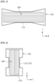
FIGS. 4 and5 are views illustrating an embodiment in which a concave surface is formed in a width direction of a housing. -
FIG. 6 is a view illustrating one embodiment of a concave surface formed as a stepped surface. -
FIG. 7 is a view illustrating one embodiment of a concave surface formed in a central portion of a housing. -
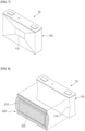
FIG. 8 is a view illustrating an embodiment including a heat absorber. - Since the present disclosure may be variously changed and have various embodiments, specific embodiments will be described in detail below.
- However, it should be understood that there is no intention to limit the present disclosure to particular embodiments, and on the contrary, the present disclosure is to cover all modifications, equivalents, and alternatives falling within the spirit and scope of the present disclosure.
- In this application, it should be understood that terms such as "include" and "have" are intended to indicate the presence of a feature, number, step, operation, component, part, or a combination thereof described in the specification, and they do not preclude the possibility of the presence or addition of one or more other features or numbers, steps, operations, components, parts or combinations thereof.
- Also, when a first portion such as a layer, a film, an area, a plate, etc. is referred to as being "on" a second portion, this includes not only the case where the first portion is "directly on" the second portion, but also the case where a third portion is interposed therebetween. On the other hand, when a first portion such as a layer, a film, an area, a plate, etc. is referred to as being "under" a second portion, this includes not only the case where the first portion is "directly under" the second portion, but also the case where a third portion is interposed therebetween. In addition, to be disposed "on" in the present application may include the case of being disposed at the bottom as well as the top.
- The present disclosure relates to a prismatic secondary battery including a housing made of a metal and having a hexahedral shape, and one or more electrode assemblies inserted through an open surface formed at an upper surface of the housing and accommodated in the housing.
- In the prismatic secondary battery of the present disclosure, in an example, a concave surface is formed in at least one surface of a front surface and a rear surface of the housing. The electrode assembly is supported by contact with the concave surface, and an insertion end portion of the electrode assembly has a wedge shape.
- In the prismatic secondary battery of the present disclosure, due to such a configuration, since the electrode assembly is supported by contact with the concave surface formed in the housing, various problems such as damage to an electrode tab caused by the movement of the electrode assembly in the housing are prevented.
- In addition, even when a swelling phenomenon in which the electrode assembly swells occurs, the deformation of the housing having improved structural rigidity due to the concave surface is suppressed, thereby improving the safety of the prismatic secondary battery.
- In the electrode assembly included in the prismatic secondary battery of the present disclosure, since the insertion end portion has a wedge shape, the risk that the electrode assembly is damaged by the concave surface when the electrode assembly is inserted into the housing is considerably reduced, and thus the structure of the electrode assembly also considerably improves the safety of the prismatic secondary battery.
- Hereinafter, specific embodiments of a prismatic secondary battery of the present disclosure will be described with reference to the accompanying drawings. For reference, front and rear directions or up, down, left, and right directions for designating relative positions used in the following descriptions are intended to help the understanding of the present disclosure and are based on directions shown in the drawings unless otherwise specified.
-
FIG. 1 is an exploded perspective view of a prismaticsecondary battery 10 according to the present disclosure.FIG. 2 is a cross-sectional view illustrating the prismaticsecondary battery 10 along cutting line A-A ofFIG. 1 . - The prismatic
secondary battery 10 of the present disclosure includes ahousing 100 made of a metal and having a hexahedral shape, and one ormore electrode assemblies 200 inserted through an open surface formed at an upper surface of thehousing 100 and accommodated therein - Here, in the structures of the
housing 100 and theelectrode assembly 200 of the prismaticsecondary battery 10 of the present disclosure, aconcave surface 110 is formed in at least one surface of front and rear surfaces of thehousing 100, and thus theelectrode assembly 200 is supported by contact with theconcave surface 110. In addition, aninsertion end portion 210 of theelectrode assembly 200 has a wedge shape. - Here, the accompanying drawings show an embodiment in which the
concave surface 110 is formed in each of the front and rear surfaces of thehousing 100. Although not shown in the drawings, as long as theconcave surface 110 may be in contact with theelectrode assembly 200 to support theelectrode assembly 200, theconcave surface 110 may be formed in only one surface of the front surface and the rear surface. Theinsertion end portion 210 of theelectrode assembly 200 refers to one end portion forming a leading end when theelectrode assembly 200 is inserted through the open upper surface of thehousing 100. That is, the one end portion of theelectrode assembly 200 that first enters an inner space of thehousing 100 corresponds to theinsertion end portion 210. - Since the
insertion end portion 210 having the wedge shape can reduce the capacity of theelectrode assembly 200, theinsertion end portion 210 may be preferably formed to have an appropriate length so as to not be in contact with theconcave surface 110 when theelectrode assembly 200 is completely accommodated in thehousing 100. - In the prismatic
secondary battery 10 of the present disclosure, since a concave portion is formed in the front and/or rear surface of thehousing 100, theelectrode assembly 200 is supported by contact with theconcave surface 110, and thus various problems such as damage to an electrode tab caused by theelectrode assembly 200 moving in thehousing 100 are prevented. - In addition, even when a swelling phenomenon in which the
electrode assembly 200 swells occurs, the deformation of thehousing 100 having improved structural rigidity due to theconcave surface 110 is suppressed, thereby improving the safety of the prismaticsecondary battery 10. - As the
electrode assembly 200 has theinsertion end portion 210 formed in a wedge shape, the risk that theelectrode assembly 200 may be damaged by theconcave surface 110 when theelectrode assembly 200 is inserted into thehousing 100, for example, the risk that a separator serving to insulate theelectrode assembly 200 may be torn, is reduced, and thus theelectrode assembly 200, which has the wedge-shapedinsertion end portion 210, also considerably improves the safety of the prismaticsecondary battery 10. - In one embodiment of the present disclosure, the
concave surface 110 is formed in any one direction of a width direction W and a height direction H of thehousing 100. Theconcave surface 110 is continuously formed from one end to the other end in any one direction of the width direction W and the height direction H. That is, theconcave surface 110 is formed to be long over the entire central portion of the front and/or rear surface of thehousing 100 in the width direction W or height direction H. -
FIGS. 1 to 3 illustrate an example of an embodiment in which theconcave surface 110 is formed in the width direction W of thehousing 100, andFIGS. 4 and5 illustrate an example of an embodiment in which theconcave surface 110 is formed in the width direction W of thehousing 100. Here, in the accompanying drawings, in order for the cross-sectional shape of theconcave surface 110 to be clearly understood,FIGS. 2 and3 illustrate a cross section in the height direction H, andFIGS. 4 and5 illustrate a cross section in the width direction W. - As shown, the
concave surface 110 may be formed curved or flat. The curvedconcave surface 110 is advantageous in that the curvedconcave surface 110 elastically supports theelectrode assembly 200, and the flatconcave surface 110 is advantageous in that a contact area with theelectrode assembly 200 is widened. - The
concave surface 110 in the embodiments ofFIGS. 1 to 5 is connected to each of both ends in the height direction H or the width direction W, which intersects a direction in which theconcave surface 110 extends, as a curved surface or a flat surface. That is, theconcave surface 110 is gently connected to a peripheral edge as a curved surface or a flat surface. The gentle shape of theconcave surface 110 is advantageous for plastic processing of thehousing 100. - Meanwhile, the
concave surface 110 provided in the prismaticsecondary battery 10 of the present disclosure may have other modified shapes, and such modified embodiments are shown inFIGS. 6 and7 . -
FIG. 6 illustrates an embodiment of theconcave surface 110 formed as a steppedsurface 112. An example of a housing in which theconcave surface 110, which is the steppedsurface 112, is formed in the width direction W of thehousing 100 is shown. The concave steppedsurface 112 including a curved step surface is in contact with an outer surface of theelectrode assembly 200 to support theelectrode assembly 200. -
FIG. 7 illustrates a modified embodiment in which theconcave surface 110 is formed in a central portion of at least one surface of the front and rear surfaces of thehousing 100. That is, theconcave surface 110 inFIG. 7 is not formed continuously from one end to the other end in any one direction of the width direction W and the height direction H of thehousing 100, rather the central portion forms a concave surface. - Here, it may be preferable that the
concave surface 110 have a structure connected to an edge of thehousing 100 through a continuous inclined surface such that theconcave surface 110 formed in the central portion may elastically support theelectrode assembly 200. In other words, a surface profile of theconcave surface 110 ofFIG. 7 has a shape similar to a quadrangular frustum pyramid. - As described above, in the prismatic
secondary battery 10 of the present disclosure, theelectrode assembly 200 is supported by contact with theconcave surface 110 formed in thehousing 100 so that internal movement is suppressed. In addition, since theinsertion end portion 210 of theelectrode assembly 200 has the wedge shape, the risk of damage when theelectrode assembly 200 is inserted into thehousing 100 is reduced. -
FIG. 8 is a view illustrating a prismaticsecondary battery 10 according to a second embodiment of the present disclosure. The illustrated prismaticsecondary battery 10 further include aheat absorber 300 disposed in an external space formed by aconcave surface 110. - The
heat absorber 300 is a component that promotes stable operation by absorbing heat generated from the prismaticsecondary battery 10. In particular, theheat absorber 300 serves to delay a fire or explosion by effectively absorbing heat in an overheating situation such as thermal runaway or the like. In addition, theheat absorber 300 also performs a heat insulating function of suppressing heat transfer between adjacent batteries. - As described above, in the second embodiment of the present disclosure, by using the space of the
concave surface 110 formed on a front and/or rear surface of the prismaticsecondary battery 10, theheat absorber 300 may be disposed in the space to smoothly cool the prismaticsecondary battery 10, thereby achieving effective cooling without additionally providing a separate cooling space. - In the illustrated second embodiment, an
exterior material 310 of theheat absorber 300 is a pouch, and the pouch, which is theexterior material 310, seals anabsorbent material 320 impregnated with a liquid that absorbs external heat and is vaporized. - Here, the
absorbent material 320 impregnated with a liquid having a heat absorbing function may be anabsorbent material 320 including a super absorbent matrix, for example, a super absorbent polymer (SAP) or a super absorbent fiber (SAF). The super absorbent matrix is porous or fibrous and exhibits a capillary action, and thus it is possible to absorb a large amount of liquid, and SAFs may be made into a fiber form, such as a nonwoven fabric, by processing SAPs. - In the present disclosure, specific types of the SAP and the SAF produced therefrom are not particularly limited, and any material having an excellent ability to absorb a fluid, particularly, water, may be used without limitation. Examples of the SAP may include at least one selected from the group consisting of polyacrylic acid, a polyacrylic salt, a polyacrylate graft polymer, starch, crosslinked carboxymethylated cellulose, an acrylic acid copolymer, a hydrolyzed starch-acrylonitrile graft copolymer, a starch-acrylic acid graft copolymer, a saponified vinyl acetate-acrylic acid ester copolymer, a hydrolyzed acrylonitrile copolymer, a hydrolyzed acrylamide copolymer, an ethylene-maleic anhydride copolymer, an isobutylene-maleic anhydride copolymer, polyvinylsulfonic acid, polyvinylphosphonic acid, polyvinyl phosphoric acid, polyvinyl sulfuric acid, sulfonated polystyrene, polyvinylamine, polydialkylaminoalkyl(meth)acrylamide, polyethyleneimine, polyallylamine, polyallylguanidine, polydimethyldiallylammonium hydroxide, a quaternized polystyrene derivative, guanidine-modified polystyrene, quaternized poly((meth)acrylamide, polyvinylguanidine, and a mixture thereof and may preferably include at least one selected from the group consisting of a crosslinked polyacrylic salt, crosslinked polyacrylic acid, and a crosslinked acrylic acid copolymer, but the present disclosure is not limited thereto.
- The type of acrylic acid copolymer used as the SAP in the present disclosure is not particularly limited, but preferably, the acrylic acid copolymer may be a copolymer including at least one comonomer selected from the group consisting of an acrylic acid monomer, maleic acid, itaconic acid, acrylamide, 2-acrylamide-2-methylpropanesulfonic acid, 2-(meth)acryloylethanesulfonic acid, 2-hydroxyethyl(meth)acrylate, and styrenesulfonic acid.
- In the present disclosure, the amount of water absorbed by the SAP may be in a range of 10 g/g to 500 g/g and preferably 50 g/g to 200 g/g, but the present disclosure is not limited thereto. That is, 10 g to 500 g of water, preferably, 50 g to 200 g, may be absorbed per 1 g of the SAP.
- In the present disclosure, the duration of a cooling effect may be improved as the amount of water absorbed by the SAP is increased. However, when the amount of water absorbed by the SAP exceeds 500 g/g, since the fluidity of the SAP increases, it may be difficult to maintain a shape of the SAP, which makes effective cooling impossible, and when the amount of water absorbed by the SAP is less than 10 g/g, the duration of a cooling effect is too short, which makes it ineffective.
- In one embodiment of the present disclosure, the liquid impregnated in the absorbent material 330 may be water. Water is a material with the highest specific heat and latent heat among readily available liquids. Therefore, since the water contained in the absorbent material 330 absorbs much heat during a process in which a temperature rises to the boiling point to cause a phase change to gas, water is suitable for application as a liquid accommodated in the
heat absorber 300 of the present disclosure. - The present disclosure has been described above in more detail through the drawings and embodiments. However, the configurations described in the drawings or the embodiments in the specification are merely embodiments of the present disclosure and do not represent all the technical ideas of the present disclosure. Thus, it is to be understood that there may be various equivalents and variations that can replace them at the time of filing the present application.
-
10: prismatic secondary battery 100: housing 110: concave surface 112: stepped surface 200: electrode assembly 210: insertion end portion 300: heat absorber 310: exterior material (pouch) 320: absorbent material W: width direction H: height direction T: thickness direction
Claims (13)
- A prismatic secondary battery, comprising:a housing made of a metal and having a hexahedral shape; andone or more electrode assemblies inserted through an open surface formed at an upper surface of the housing and accommodated in the housing,wherein a concave surface is formed in at least one surface of a front surface or a rear surface of the housing,wherein the one or more electrode assemblies are supported by contacting the concave surface in the housing, andwherein an insertion end portion of the one or more electrode assemblies have a wedge shape.
- The prismatic secondary battery of claim 1, wherein the concave surface is formed along a width direction or a height direction of the housing.
- The prismatic secondary battery of claim 2, wherein the concave surface is continuously formed from one end to the other end of the housing.
- The prismatic secondary battery of claim 3, wherein the concave surface is formed curved or flat.
- The prismatic secondary battery of claim 4, wherein the concave surface is connected to both ends in the height direction or in the width direction of the housing, which intersects a direction in which the concave surface extends, as a curved surface or a flat surface.
- The prismatic secondary battery of claim 4, wherein the concave surface is formed as a stepped surface.
- The prismatic secondary battery of claim 1, wherein the concave surface is formed in a central portion of at least one surface of the front surface or the rear surface of the housing.
- The prismatic secondary battery of claim 7, wherein the concave surface is connected to an edge of the housing through a continuous inclined surface.
- The prismatic secondary battery of claim 1, wherein the insertion end portion of the one or more electrode assemblies are not in contact with the concave surface.
- The prismatic secondary battery of claim 1, further comprising:
a heat absorber disposed in a space formed by the concave surface. - The prismatic secondary battery of claim 10, wherein an exterior material of the heat absorber is a pouch, and
wherein the pouch seals an absorbent material impregnated with a liquid that absorbs external heat and is vaporized. - The prismatic secondary battery of claim 11, wherein the absorbent material is a super absorbent matrix.
- The prismatic secondary battery of claim 12, wherein the super absorbent matrix includes a super absorbent polymer (SAP) or a super absorbent fiber (SAF).
Applications Claiming Priority (2)
| Application Number | Priority Date | Filing Date | Title |
|---|---|---|---|
| KR1020220065161A KR20230165448A (en) | 2022-05-27 | 2022-05-27 | Safety improved secondary battery |
| PCT/KR2023/006594 WO2023229280A1 (en) | 2022-05-27 | 2023-05-16 | Secondary battery having enhanced safety |
Publications (2)
| Publication Number | Publication Date |
|---|---|
| EP4336630A1 true EP4336630A1 (en) | 2024-03-13 |
| EP4336630A4 EP4336630A4 (en) | 2025-02-19 |
Family
ID=88919550
Family Applications (1)
| Application Number | Title | Priority Date | Filing Date |
|---|---|---|---|
| EP23812054.7A Pending EP4336630A4 (en) | 2022-05-27 | 2023-05-16 | SECONDARY BATTERY WITH INCREASED SAFETY |
Country Status (6)
| Country | Link |
|---|---|
| US (1) | US20240291075A1 (en) |
| EP (1) | EP4336630A4 (en) |
| JP (1) | JP7772458B2 (en) |
| KR (1) | KR20230165448A (en) |
| CN (1) | CN117501517A (en) |
| WO (1) | WO2023229280A1 (en) |
Family Cites Families (13)
| Publication number | Priority date | Publication date | Assignee | Title |
|---|---|---|---|---|
| KR100601536B1 (en) * | 2004-07-29 | 2006-07-19 | 삼성에스디아이 주식회사 | Lithium ion secondary battery |
| KR20070080923A (en) * | 2006-02-09 | 2007-08-14 | 삼성에스디아이 주식회사 | Can type secondary battery |
| JP2008130371A (en) * | 2006-11-21 | 2008-06-05 | Sanyo Electric Co Ltd | Battery case, non-aqueous electrolyte secondary battery including the battery case, and method for manufacturing the non-aqueous electrolyte secondary battery |
| KR100898677B1 (en) * | 2007-03-07 | 2009-05-22 | 삼성에스디아이 주식회사 | Square Lithium Ion Battery |
| KR100997715B1 (en) * | 2008-08-28 | 2010-12-01 | 주식회사 일광캔테크 | Manufacturing method of secondary battery case |
| JP5810861B2 (en) * | 2011-11-17 | 2015-11-11 | 株式会社Gsユアサ | battery |
| JP5692045B2 (en) * | 2011-12-21 | 2015-04-01 | 株式会社豊田自動織機 | Module and vehicle |
| JP6052574B2 (en) | 2012-05-16 | 2016-12-27 | 株式会社Gsユアサ | Power storage device and method for manufacturing power storage device |
| JP2014010916A (en) * | 2012-06-27 | 2014-01-20 | Sharp Corp | Secondary battery |
| JP6414731B2 (en) * | 2013-10-01 | 2018-10-31 | 株式会社Gsユアサ | Power storage element and power storage device |
| KR102265219B1 (en) * | 2017-02-08 | 2021-06-16 | (주)엘지에너지솔루션 | Manufacturing Method of Battery Cell Comprising Step of Binding Membrane Surplus |
| CN113381099A (en) * | 2020-02-21 | 2021-09-10 | 比亚迪股份有限公司 | Battery case, battery pack, battery module and electric vehicle |
| KR20220065161A (en) | 2020-11-12 | 2022-05-20 | (주)에프씨언와이어드 | Bio sensor capsule device with wireless charging function |
-
2022
- 2022-05-27 KR KR1020220065161A patent/KR20230165448A/en active Pending
-
2023
- 2023-05-16 JP JP2023578823A patent/JP7772458B2/en active Active
- 2023-05-16 EP EP23812054.7A patent/EP4336630A4/en active Pending
- 2023-05-16 WO PCT/KR2023/006594 patent/WO2023229280A1/en not_active Ceased
- 2023-05-16 CN CN202380012370.4A patent/CN117501517A/en active Pending
- 2023-05-16 US US18/571,635 patent/US20240291075A1/en active Pending
Also Published As
| Publication number | Publication date |
|---|---|
| KR20230165448A (en) | 2023-12-05 |
| JP2024528445A (en) | 2024-07-30 |
| US20240291075A1 (en) | 2024-08-29 |
| WO2023229280A1 (en) | 2023-11-30 |
| EP4336630A4 (en) | 2025-02-19 |
| JP7772458B2 (en) | 2025-11-18 |
| CN117501517A (en) | 2024-02-02 |
Similar Documents
| Publication | Publication Date | Title |
|---|---|---|
| EP4044349B1 (en) | Battery module comprising absorption member, battery rack comprising same, and power storage system | |
| EP4329048B1 (en) | Prismatic secondary battery | |
| EP4325635B1 (en) | Battery pack with enhanced cooling performance | |
| JP7636104B2 (en) | Heat absorbing pouch assembly for secondary batteries | |
| EP4322288A1 (en) | Prismatic secondary battery with heat absorber embedded therein | |
| EP4336626A1 (en) | Prismatic secondary battery | |
| US20250293347A1 (en) | Secondary battery module with improved module interior temperature stability | |
| KR20230153919A (en) | Prismatic secondary battery including heat absorber | |
| US20240291075A1 (en) | Secondary battery having improved safety | |
| EP4318739A1 (en) | Battery pack | |
| JP7782928B2 (en) | Secondary battery module with improved temperature stability inside the module | |
| KR20230148731A (en) | Battery pack | |
| KR102307664B1 (en) | Cleaning Device for Prismatic Battery Cell Having Roller Coated with Organic Solvent | |
| CN117378082A (en) | Prismatic secondary battery with built-in heat absorber | |
| CN117296188A (en) | Battery | |
| KR20240084194A (en) | Battery block having improved cold operation performance | |
| KR20260073592A (en) | Pack case having top cooling and bottom venting structure |
Legal Events
| Date | Code | Title | Description |
|---|---|---|---|
| STAA | Information on the status of an ep patent application or granted ep patent |
Free format text: STATUS: THE INTERNATIONAL PUBLICATION HAS BEEN MADE |
|
| PUAI | Public reference made under article 153(3) epc to a published international application that has entered the european phase |
Free format text: ORIGINAL CODE: 0009012 |
|
| STAA | Information on the status of an ep patent application or granted ep patent |
Free format text: STATUS: REQUEST FOR EXAMINATION WAS MADE |
|
| 17P | Request for examination filed |
Effective date: 20231207 |
|
| AK | Designated contracting states |
Kind code of ref document: A1 Designated state(s): AL AT BE BG CH CY CZ DE DK EE ES FI FR GB GR HR HU IE IS IT LI LT LU LV MC ME MK MT NL NO PL PT RO RS SE SI SK SM TR |
|
| A4 | Supplementary search report drawn up and despatched |
Effective date: 20250120 |
|
| RIC1 | Information provided on ipc code assigned before grant |
Ipc: H01M 10/658 20140101ALI20250114BHEP Ipc: H01M 10/04 20060101ALI20250114BHEP Ipc: H01M 10/6569 20140101ALI20250114BHEP Ipc: H01M 10/613 20140101ALI20250114BHEP Ipc: H01M 10/647 20140101ALI20250114BHEP Ipc: H01M 10/659 20140101ALI20250114BHEP Ipc: H01M 50/119 20210101ALI20250114BHEP Ipc: H01M 50/103 20210101AFI20250114BHEP |
|
| STAA | Information on the status of an ep patent application or granted ep patent |
Free format text: STATUS: EXAMINATION IS IN PROGRESS |
|
| 17Q | First examination report despatched |
Effective date: 20250728 |
|
| DAV | Request for validation of the european patent (deleted) | ||
| DAX | Request for extension of the european patent (deleted) |