EP4336621A1 - Charging control method for battery pack, and battery system using same - Google Patents
Charging control method for battery pack, and battery system using same Download PDFInfo
- Publication number
- EP4336621A1 EP4336621A1 EP22919100.2A EP22919100A EP4336621A1 EP 4336621 A1 EP4336621 A1 EP 4336621A1 EP 22919100 A EP22919100 A EP 22919100A EP 4336621 A1 EP4336621 A1 EP 4336621A1
- Authority
- EP
- European Patent Office
- Prior art keywords
- battery
- charging
- charging rate
- battery pack
- value
- Prior art date
- Legal status (The legal status is an assumption and is not a legal conclusion. Google has not performed a legal analysis and makes no representation as to the accuracy of the status listed.)
- Granted
Links
Images



Classifications
-
- H—ELECTRICITY
- H02—GENERATION; CONVERSION OR DISTRIBUTION OF ELECTRIC POWER
- H02J—ELECTRIC POWER NETWORKS; CIRCUIT ARRANGEMENTS OR SYSTEMS FOR SUPPLYING OR DISTRIBUTING ELECTRIC POWER; SYSTEMS FOR STORING ELECTRIC ENERGY
- H02J7/00—Circuit arrangements for charging or discharging batteries or for supplying loads from batteries
- H02J7/90—Regulation of charging or discharging current or voltage
- H02J7/933—Regulation of charging or discharging current or voltage the cycle being controlled or terminated in response to electric parameters
-
- H—ELECTRICITY
- H01—ELECTRIC ELEMENTS
- H01M—PROCESSES OR MEANS, e.g. BATTERIES, FOR THE DIRECT CONVERSION OF CHEMICAL ENERGY INTO ELECTRICAL ENERGY
- H01M10/00—Secondary cells; Manufacture thereof
- H01M10/42—Methods or arrangements for servicing or maintenance of secondary cells or secondary half-cells
- H01M10/44—Methods for charging or discharging
- H01M10/441—Methods for charging or discharging for several batteries or cells simultaneously or sequentially
-
- G—PHYSICS
- G05—CONTROLLING; REGULATING
- G05B—CONTROL OR REGULATING SYSTEMS IN GENERAL; FUNCTIONAL ELEMENTS OF SUCH SYSTEMS; MONITORING OR TESTING ARRANGEMENTS FOR SUCH SYSTEMS OR ELEMENTS
- G05B11/00—Automatic controllers
- G05B11/01—Automatic controllers electric
- G05B11/36—Automatic controllers electric with provision for obtaining particular characteristics, e.g. proportional, integral, differential
- G05B11/42—Automatic controllers electric with provision for obtaining particular characteristics, e.g. proportional, integral, differential for obtaining a characteristic which is both proportional and time-dependent, e.g. P. I., P. I. D.
-
- G—PHYSICS
- G05—CONTROLLING; REGULATING
- G05B—CONTROL OR REGULATING SYSTEMS IN GENERAL; FUNCTIONAL ELEMENTS OF SUCH SYSTEMS; MONITORING OR TESTING ARRANGEMENTS FOR SUCH SYSTEMS OR ELEMENTS
- G05B19/00—Program-control systems
- G05B19/02—Program-control systems electric
- G05B19/18—Numerical control [NC], i.e. automatically operating machines, in particular machine tools, e.g. in a manufacturing environment, so as to execute positioning, movement or co-ordinated operations by means of program data in numerical form
- G05B19/4155—Numerical control [NC], i.e. automatically operating machines, in particular machine tools, e.g. in a manufacturing environment, so as to execute positioning, movement or co-ordinated operations by means of program data in numerical form characterised by program execution, i.e. part program or machine function execution, e.g. selection of a program
-
- H—ELECTRICITY
- H01—ELECTRIC ELEMENTS
- H01M—PROCESSES OR MEANS, e.g. BATTERIES, FOR THE DIRECT CONVERSION OF CHEMICAL ENERGY INTO ELECTRICAL ENERGY
- H01M10/00—Secondary cells; Manufacture thereof
- H01M10/42—Methods or arrangements for servicing or maintenance of secondary cells or secondary half-cells
- H01M10/425—Structural combination with electronic components, e.g. electronic circuits integrated to the outside of the casing
-
- H—ELECTRICITY
- H01—ELECTRIC ELEMENTS
- H01M—PROCESSES OR MEANS, e.g. BATTERIES, FOR THE DIRECT CONVERSION OF CHEMICAL ENERGY INTO ELECTRICAL ENERGY
- H01M10/00—Secondary cells; Manufacture thereof
- H01M10/42—Methods or arrangements for servicing or maintenance of secondary cells or secondary half-cells
- H01M10/44—Methods for charging or discharging
- H01M10/443—Methods for charging or discharging in response to temperature
-
- H—ELECTRICITY
- H01—ELECTRIC ELEMENTS
- H01M—PROCESSES OR MEANS, e.g. BATTERIES, FOR THE DIRECT CONVERSION OF CHEMICAL ENERGY INTO ELECTRICAL ENERGY
- H01M10/00—Secondary cells; Manufacture thereof
- H01M10/42—Methods or arrangements for servicing or maintenance of secondary cells or secondary half-cells
- H01M10/48—Accumulators combined with arrangements for measuring, testing or indicating the condition of cells, e.g. the level or density of the electrolyte
- H01M10/482—Accumulators combined with arrangements for measuring, testing or indicating the condition of cells, e.g. the level or density of the electrolyte for several batteries or cells simultaneously or sequentially
-
- H—ELECTRICITY
- H01—ELECTRIC ELEMENTS
- H01M—PROCESSES OR MEANS, e.g. BATTERIES, FOR THE DIRECT CONVERSION OF CHEMICAL ENERGY INTO ELECTRICAL ENERGY
- H01M10/00—Secondary cells; Manufacture thereof
- H01M10/42—Methods or arrangements for servicing or maintenance of secondary cells or secondary half-cells
- H01M10/48—Accumulators combined with arrangements for measuring, testing or indicating the condition of cells, e.g. the level or density of the electrolyte
- H01M10/486—Accumulators combined with arrangements for measuring, testing or indicating the condition of cells, e.g. the level or density of the electrolyte for measuring temperature
-
- H—ELECTRICITY
- H02—GENERATION; CONVERSION OR DISTRIBUTION OF ELECTRIC POWER
- H02J—ELECTRIC POWER NETWORKS; CIRCUIT ARRANGEMENTS OR SYSTEMS FOR SUPPLYING OR DISTRIBUTING ELECTRIC POWER; SYSTEMS FOR STORING ELECTRIC ENERGY
- H02J7/00—Circuit arrangements for charging or discharging batteries or for supplying loads from batteries
- H02J7/50—Circuit arrangements for charging or discharging batteries or for supplying loads from batteries acting upon multiple batteries simultaneously or sequentially
-
- H—ELECTRICITY
- H02—GENERATION; CONVERSION OR DISTRIBUTION OF ELECTRIC POWER
- H02J—ELECTRIC POWER NETWORKS; CIRCUIT ARRANGEMENTS OR SYSTEMS FOR SUPPLYING OR DISTRIBUTING ELECTRIC POWER; SYSTEMS FOR STORING ELECTRIC ENERGY
- H02J7/00—Circuit arrangements for charging or discharging batteries or for supplying loads from batteries
- H02J7/80—Circuit arrangements for charging or discharging batteries or for supplying loads from batteries including monitoring or indicating arrangements
- H02J7/82—Control of state of charge [SOC]
-
- H—ELECTRICITY
- H02—GENERATION; CONVERSION OR DISTRIBUTION OF ELECTRIC POWER
- H02J—ELECTRIC POWER NETWORKS; CIRCUIT ARRANGEMENTS OR SYSTEMS FOR SUPPLYING OR DISTRIBUTING ELECTRIC POWER; SYSTEMS FOR STORING ELECTRIC ENERGY
- H02J7/00—Circuit arrangements for charging or discharging batteries or for supplying loads from batteries
- H02J7/90—Regulation of charging or discharging current or voltage
- H02J7/96—Regulation of charging or discharging current or voltage in response to battery voltage
-
- H—ELECTRICITY
- H02—GENERATION; CONVERSION OR DISTRIBUTION OF ELECTRIC POWER
- H02J—ELECTRIC POWER NETWORKS; CIRCUIT ARRANGEMENTS OR SYSTEMS FOR SUPPLYING OR DISTRIBUTING ELECTRIC POWER; SYSTEMS FOR STORING ELECTRIC ENERGY
- H02J7/00—Circuit arrangements for charging or discharging batteries or for supplying loads from batteries
- H02J7/90—Regulation of charging or discharging current or voltage
- H02J7/971—Regulation of charging or discharging current or voltage the charge cycle being controlled or terminated in response to non-electric parameters
- H02J7/975—Regulation of charging or discharging current or voltage the charge cycle being controlled or terminated in response to non-electric parameters in response to temperature
- H02J7/977—Regulation of charging or discharging current or voltage the charge cycle being controlled or terminated in response to non-electric parameters in response to temperature of the battery
-
- G—PHYSICS
- G05—CONTROLLING; REGULATING
- G05B—CONTROL OR REGULATING SYSTEMS IN GENERAL; FUNCTIONAL ELEMENTS OF SUCH SYSTEMS; MONITORING OR TESTING ARRANGEMENTS FOR SUCH SYSTEMS OR ELEMENTS
- G05B2219/00—Program-control systems
- G05B2219/30—Nc systems
- G05B2219/42—Servomotor, servo controller kind till VSS
- G05B2219/42033—Kind of servo controller
-
- H—ELECTRICITY
- H01—ELECTRIC ELEMENTS
- H01M—PROCESSES OR MEANS, e.g. BATTERIES, FOR THE DIRECT CONVERSION OF CHEMICAL ENERGY INTO ELECTRICAL ENERGY
- H01M10/00—Secondary cells; Manufacture thereof
- H01M10/42—Methods or arrangements for servicing or maintenance of secondary cells or secondary half-cells
- H01M10/425—Structural combination with electronic components, e.g. electronic circuits integrated to the outside of the casing
- H01M2010/4271—Battery management systems including electronic circuits, e.g. control of current or voltage to keep battery in healthy state, cell balancing
-
- Y—GENERAL TAGGING OF NEW TECHNOLOGICAL DEVELOPMENTS; GENERAL TAGGING OF CROSS-SECTIONAL TECHNOLOGIES SPANNING OVER SEVERAL SECTIONS OF THE IPC; TECHNICAL SUBJECTS COVERED BY FORMER USPC CROSS-REFERENCE ART COLLECTIONS [XRACs] AND DIGESTS
- Y02—TECHNOLOGIES OR APPLICATIONS FOR MITIGATION OR ADAPTATION AGAINST CLIMATE CHANGE
- Y02E—REDUCTION OF GREENHOUSE GAS [GHG] EMISSIONS, RELATED TO ENERGY GENERATION, TRANSMISSION OR DISTRIBUTION
- Y02E60/00—Enabling technologies; Technologies with a potential or indirect contribution to GHG emissions mitigation
- Y02E60/10—Energy storage using batteries
Definitions
- the present disclosure relates to a charging control method of a battery pack and a battery system using the same.
- a battery management system receives a target SOC and a current temperature as initial conditions, and determines a C-rate corresponding to the initial conditions on a rapid charging map.
- the BMS transmits the determined C-rate value to the vehicle or a cycler, and the vehicle or cycler performs the rapid charging by applying the current to the battery cell or the module according to the transmitted C-rate.
- a drawback of this method is that the effect caused by the degeneration of the cell cannot be considered in the rapid charging process.
- the cell voltage may exceed an upper limit voltage that should not be exceeded during the rapid charging process.
- the upper limit voltage may be different depending on the SOC level.
- the present disclosure is intended to provide a charging control method for a battery pack that may prevent the phenomenon of exceeding the upper limit voltage due to the cell degeneration in advance while maintaining the rapid charging speed as much as possible.
- a battery system may include: a battery pack including a plurality of battery cells; and a battery management system configured to derive a charging rate based on a charging target SOC (State of Charge) for the battery pack and the battery pack temperature, and compensate for the charging rate through PID control based on an error voltage between any one of the plurality of cell voltages and an open circuit voltage (OCV) corresponding to the charging target SOC to generate a compensation charging rate.
- SOC Sty of Charge
- OCV open circuit voltage
- the battery management system may generate a proportional value, an integral value, and a differential value based on the error voltage to derive a PID value, and multiplies the charging rate by the PID value to generate the compensation charging rate.
- the battery management system may derive the PID value by adding the proportional value, the integral value, and the differential value.
- the battery management system may include a charging rate map in which a charging rate corresponding to each temperature of a plurality of battery packs is defined for each of a plurality of charging targets SOCs, and receives the charging target SOC and the battery pack temperature, and derives the charging rate corresponding to the received charging target SOC and battery pack temperature from the charging rate map.
- the battery management system may generate the OCV corresponding to the charging target SOC by using an SOC to OCV conversion function.
- the battery management system may generate the error voltage by subtracting the highest cell voltage among the plurality of cell voltages from the OCV.
- the battery management system may generate a modulation charging rate by multiplying the compensation charging rate by p.
- a charging control method of a battery pack including a plurality of battery cells controlled by a battery management system may include: deriving a charging rate based on a charging target State of Charge (SOC) for the battery pack and a battery pack temperature; generating an error voltage between any one of the plurality of cell voltages and an open circuit voltage (OCV) corresponding to the charging target SOC; and generating a compensation charging rate by compensating for the charging rate through PID control based on the error voltage.
- SOC State of Charge
- OCV open circuit voltage
- the generating of the compensation charging rate may include: generating a proportional value, an integral value, and a differential value based on the error voltage; deriving a PID value by adding the proportional value, the integral value, and the differential value; and multiplying the charging rate by the PID value to generate the compensation charging rate.
- the deriving of the charging rate may include: receiving the charging target SOC and the battery pack temperature; and deriving the charging rate corresponding to the received charging target SOC and battery pack temperature from a charging rate map.
- the charging control method of the battery pack may further include generating the OCV corresponding to the charging target SOC by using an SOC to OCV conversion function.
- the generating of the error voltage may include generating the error voltage by subtracting the highest cell voltage among the plurality of cell voltages from the OCV.
- the charging control method of the battery pack may further include, in the plurality of battery cells, when battery cell groups in which battery cells are connected in parallel with p are connected in series with s, generating a modulation charging rate by multiplying the compensation charging rate by p.
- the present disclosure provides the method for controlling the charging of the battery pack, and the battery system using the method so that the cell voltage does not exceed the upper limit voltage.
- An embodiment of the present disclosure may control a charging speed through PID control based on a charging target SOC and a cell voltage in order to prevent a cell from exceeding an upper limit voltage during charging.
- the PID control applied to an embodiment is a well-known control method, but by being applied to an embodiment, a heterogeneous effect capable of preventing an upper limit voltage exceeding phenomenon of a cell during the charging may be provided.
- the PID (Proportional-Integral-Differential) control is a form of negative feedback control, which measures an output value of a controlled object, compares it with a reference value based on a control target to calculate an error, and uses a proportional term, an integral term, and a differential term by this error value, so that a control value (hereinafter, a PID value) required to control a control target may be calculated.
- the output value may be a cell voltage
- the reference value may be an OCV (Open Circuit Voltage) corresponding to the charging target SOC
- the PID value may be a weight value multiplied by a charging speed.
- the proportional term may be a value proportional to the magnitude of the error value in the current state
- the integral term may eliminate a steady-state error
- the differential term may reduce an overshoot and improve stability by braking sudden changes in the output value.
- the charging speed may be expressed as a charging rate (C-rate) hereinafter.
- the charging rate (C-rate) means a magnitude of a charging current ([A]) or a discharging current ([A]) for a rated capacity of the battery when charging or discharging, and "C” is used for the "unit" of the C-rate. This is expressed as Equation 1 below. As seen from Equation 1, the unit of the rated capacity of the battery is not considered in the C-rate.
- C-rate charging or discharging current A / rated capacity of battery
- a program implemented as a set of instructions embodying a control algorithm necessary to control another configuration may be installed in a configuration for controlling another configuration under a specific control condition among configurations according to an embodiment.
- the control configuration may process input data and stored data, based on the installed program to generate output data.
- the control configuration may include a nonvolatile memory storing the program and a memory storing the data.
- FIG. 1 is a view showing a battery system according to an embodiment.
- a battery system 1 is connected to a power converter 2.
- the power converter 2 may supply power supplied from the battery pack 10 by the discharge of the battery pack 10 to an external load (e.g., a motor that provides driving power to an electric vehicle).
- Electric vehicles include vehicles driven only by a motor without an internal combustion engine and hybrid vehicles that include both an internal combustion engine and a motor.
- the power converter 2 may supply the power for charging the battery pack 10 from an external commercial power source.
- the power converter 2 may be a charging and discharging device for testing battery performance like a CYCLER.
- the power converter 2 may be a device that transfers the power from the battery pack 10 to the outside or from the outside to the battery pack 10 according to the discharging or charging of the battery pack 10.
- the battery system 1 includes a battery pack 10, a BMS 20, and first and second contactors 101 and 102.
- the first contactor 101 is connected between a positive electrode (P+) of the battery pack 10 and the power converter 40, and is switched under the control of the BMS 20.
- the second contactor 102 is connected between the negative electrode (P-) of the battery pack 10 and the power converter 2, and is switched under the control of the BMS 20.
- the BMS 20 may generate and supply switching signals SC1 and SC2 that control the switching operations of the first and second contactors 101 and 102 to the first and second contactors 101 and 102.
- the battery pack 10 includes a plurality of battery cells 10_1 to 10_n (n is two or more natural numbers) connected in series.
- the BMS 20 is connected to both terminals of each of a plurality of battery cells 10_1 to 10_n.
- the BMS 20 may measure the cell voltage of each of a plurality of battery cells 10_1 to 10_n at each monitoring period, and may measure the current (hereinafter, a battery pack current) and temperature (hereinafter, a battery pack temperature) of the battery pack 10.
- the temperature of a plurality of battery cells 10_1 to 10_n may follow the battery pack temperature.
- a plurality of temperature sensors may be disposed in the battery pack 10, and the BMS 20 may estimate the temperature for each of a plurality of battery cells 10_1 to 10_n based on temperature information obtained from a plurality of temperature sensors.
- the battery pack temperature may be replaced with the battery cell temperature.
- the current sensor 21 may measure the battery pack current IB and transmit the information about the measured battery pack current to the BMS 20.
- the temperature sensor 22 may measure the battery pack temperature and transmit the information about the measured battery pack temperature to the BMS 20.
- the BMS 20 may control and perform cell balancing for a plurality of battery cells 10_1 to 10_n based on a plurality of cell voltages.
- the BMS 20 may estimate an SOC (State of Charge), an SOH (State of Health), an SOP (State of Power), etc. based on a plurality of cell voltages of a plurality of battery cells 10_1 to 10_n and the measured information (the battery pack current, the battery pack temperature, etc.) of the battery pack 10.
- the BMS 20 may determine a charging rate based on the charging target SOC for the battery pack 10, a plurality of cell voltages, and the battery pack temperature.
- the charging target SOC may be transmitted to the BMS 20 through CAN communication from an electronic control circuit that controls the electric vehicle when the battery system 1 is installed in the electric vehicle.
- the user may transmit the charging target SOC to the BMS 20 through the interface for the battery performance test.
- the BMS 20 may include a map (hereinafter, a charging rate map) in which the charging rate is set based on the charging target SOC and the battery pack temperature.
- a charging rate map a charging rate according to each of a plurality of battery pack temperatures is defined for each of a plurality of charging targets SOC.
- the BMS 20 may derive a target OCV corresponding to the charging target SOC.
- the BMS 20 generates an error voltage, which is the difference between the target OCV and one of a plurality of cell voltages, for each monitoring period, derives a PID value based on the error voltage for each monitoring period, and multiplies the derived PID value by the charging rate determined based on the charging target SOC and the battery pack temperature to generate a compensating charging rate.
- the BMS 20 transmits the compensation charging rate to the power converter 2.
- the power converter 2 may supply the power to the battery pack 10 according to the compensation charging rate.
- the BMS 20 may repeat the PID value derivation and the compensation charging rate generation described above for each monitoring period.
- FIG. 2 is a block diagram showing some components of a BMS according to an embodiment.
- FIG. 3 is a flowchart showing an operation of a BMS according to an embodiment.
- FIG. 2 shows, as configurations of the BMS 20, only configurations necessary to generate the compensation charging rate by deriving the PID value.
- the BMS 20 may include a charging rate derivation unit 21, an OCV conversion unit 22, a subtraction unit 23, a proportional unit 24, an integration unit 25, a differential unit 26, a summing unit 27, and a multiplication unit 28.
- Each of the components 21 to 28 constituting the BMS 20 is a module to perform a corresponding function, and a program including control instructions for performing the corresponding function may be installed in the corresponding module.
- Each of the charging rate derivation unit 21, the OCV conversion unit 22, the subtraction unit 23, the proportional unit 24, the integration unit 25, the differential unit 26, the summing unit 27, and the multiplication unit 28 may operate according to the installed program and generate the output according to the input.
- the charging rate derivation unit 21 stores the charging rate map.
- the charging rate derivation unit 21 receives the charging target SOC and the battery pack temperature, and derives the charging rate cr1 from the charging rate map based on the charging target SOC and the battery pack temperature (S1).
- the OCV conversion unit 22 includes a program that implements a SOC to OCV conversion function, and upon receiving the charging target SOC, it may generate the OCV corresponding to the charging target SOC using the program (S2).
- the subtraction unit 23 may generate an error voltage ve by subtracting the cell voltage vc from the OCV (S3).
- the cell voltage vc may be a cell voltage (hereinafter, a highest cell voltage) that is highest among a plurality of cell voltages. There may be a difference between a plurality of cell voltages, and when the PID value is derived based on the lower cell voltage than the highest cell voltage among a plurality of cell voltages, overcharging may occur for the cell having the highest cell voltage. This may cause the cell voltage of the corresponding cell to become the overvoltage.
- the proportional unit 24, the integration unit 25, and the differential unit 26 for deriving the PID value may receive the error voltage ve for each monitoring period.
- the proportional parameter, the integral parameter, and the differential parameter for deriving the PID value may be set through tuning using an experimental method.
- the proportional unit 24 multiplies the error voltage ve by a predetermined proportional parameter to generate a proportional value pv (S4).
- the integration unit 25 multiplies the result of integrating the error voltage ve with respect to time by the integration parameter to generate an integral value iv (S5).
- the integration period may be a period between the previous monitoring time point and the current monitoring time point, that is, a monitoring cycle. That is, the integration unit 25 may generate an integral value iv by multiplying an integral parameter by the result obtained by multiplying the error voltage ve by the monitoring cycle.
- the differential unit 26 generates a differential value dv by multiplying the differential parameter by the result of differentiating the error voltage ve with respect to time (S6).
- the differential period may also be a monitoring cycle. That is, the differential unit 26 may generate a differential value dv by multiplying a value obtained by dividing a value obtained by subtracting the error voltage at the previous monitoring time point from the error voltage ve at the current monitoring time point by a monitoring cycle by a differential parameter.
- the summing unit 27 generates the PID value by summing the proportional value pv, the integral value iv, and the differential value dv (S7).
- the multiplication unit 28 multiplies the charging rate cr1 by the PID value to generate the compensation charging rate cr2 (S8).
- the BMS 20 may transmit the compensation charging rate cr2 to the power converter 2, and the power converter 2 may charge the battery pack 10 with a charging current depending on the compensation charging rate cr2.
- the BMS 20 may perform the above-described operation by measuring the cell voltages of a plurality of battery cells 10_1 to 10_n in the next monitoring cycle and deriving the highest cell voltage among a plurality of cell voltages. In this way, the BMS 20 may generate the compensation charging rate based on the highest cell voltage for each monitoring cycle.
- the present invention is not limited thereto, and the compensation charging rate may be generated for every predetermined integer multiple of the monitoring cycle.
- FIG. 4 is a block diagram showing a configuration of a BMS according to an embodiment.
- FIG. 5 is a circuit diagram showing a battery pack according to an embodiment.
- the BMS 20 further includes a modulator 29 compared to the preceding embodiment.
- the modulator 29 may modulate the compensation charging rate according to the structure of a plurality of battery cells constituting the battery pack 10.
- FIG. 1 shows that a plurality of battery cells 10_1 to 10_n are connected in series, but the battery pack 10' shown in FIG. 5 may include the battery cells connected in parallel to each of a plurality of battery cells 10_1 to 10_n.
- One of a plurality of battery cells 10_1 to 10_n and one of a plurality of battery cells 11_1 to 11_n are connected in parallel to form a battery cell group, and the plurality of battery cell groups that are connected in parallel are connected in series.
- FIG. 5 is an example of a case where battery cell groups in which battery cells are connected in parallel with p are connected in series with s (p and s are natural numbers of 2 or more).
- the modulator 29 may generate a modulation charging rate cr3 obtained by multiplying the compensation charging rate cr2 by a proportional constant 2 considering two current paths in parallel.
- the modulator 29 may determine a proportional constant value according to the number of battery cells connected in parallel, that is, p. For example, when the number of battery cells connected in parallel is 3, the proportional constant may be 3.
- the BMS 20 may transmits the modulated charging rate cr3 to the power converter 2, and the power converter 2 may charge the battery pack 10 with the charging current according to the modulated charging rate cr3.
- the conventional rapid charging method proceeds with the charging at a constant C-Rate, but reduces the current when the cell voltage exceeds the upper limit voltage.
- the charging method converts the charging target SOC to the OCV, sets the upper limit voltage in the charging for the charging target SOC, and controls the PID based on the error voltage between a plurality of battery cell voltages and the OCV, thereby it is possible to prevent the cell voltage from exceeding the upper limit voltage.
Landscapes
- Engineering & Computer Science (AREA)
- Manufacturing & Machinery (AREA)
- Power Engineering (AREA)
- General Chemical & Material Sciences (AREA)
- Chemical Kinetics & Catalysis (AREA)
- Electrochemistry (AREA)
- Chemical & Material Sciences (AREA)
- Microelectronics & Electronic Packaging (AREA)
- Physics & Mathematics (AREA)
- General Physics & Mathematics (AREA)
- Automation & Control Theory (AREA)
- Human Computer Interaction (AREA)
- Charge And Discharge Circuits For Batteries Or The Like (AREA)
- Secondary Cells (AREA)
Abstract
Description
- This application claims priority to and the benefit of
Korean Patent Application No. 10-2022-0002136 filed in the Korean Intellectual Property Office on January 06, 2022 - The present disclosure relates to a charging control method of a battery pack and a battery system using the same.
- Existing fast charging methods operate based on a rapid charging map composed of fixed C-rates according to an SOC and a temperature. For example, a battery management system (BMS) receives a target SOC and a current temperature as initial conditions, and determines a C-rate corresponding to the initial conditions on a rapid charging map. The BMS transmits the determined C-rate value to the vehicle or a cycler, and the vehicle or cycler performs the rapid charging by applying the current to the battery cell or the module according to the transmitted C-rate. A drawback of this method is that the effect caused by the degeneration of the cell cannot be considered in the rapid charging process. In general, when the cell degenerates, since an internal resistance increases, a larger voltage is output at the same SOC compared to the initial production time. Due to this, the cell voltage may exceed an upper limit voltage that should not be exceeded during the rapid charging process. The upper limit voltage may be different depending on the SOC level.
- The phenomenon of exceeding the upper limit voltage due to the cell degeneration continues to occur as the number of the rapid charging cycles is repeated, which has a negative effect of further accelerating the cell degeneration. When the cell voltage exceeding the upper limit voltage occurs, there is an improvement method to reduce the current magnitude to a certain ratio. However, since it is impossible to predict the voltage change due to the cell degeneration due to various factors, a method of reducing the current magnitude to a constant ratio is not effective.
- The present disclosure is intended to provide a charging control method for a battery pack that may prevent the phenomenon of exceeding the upper limit voltage due to the cell degeneration in advance while maintaining the rapid charging speed as much as possible.
- A battery system may include: a battery pack including a plurality of battery cells; and a battery management system configured to derive a charging rate based on a charging target SOC (State of Charge) for the battery pack and the battery pack temperature, and compensate for the charging rate through PID control based on an error voltage between any one of the plurality of cell voltages and an open circuit voltage (OCV) corresponding to the charging target SOC to generate a compensation charging rate.
- The battery management system may generate a proportional value, an integral value, and a differential value based on the error voltage to derive a PID value, and multiplies the charging rate by the PID value to generate the compensation charging rate.
- The battery management system may derive the PID value by adding the proportional value, the integral value, and the differential value.
- The battery management system may include a charging rate map in which a charging rate corresponding to each temperature of a plurality of battery packs is defined for each of a plurality of charging targets SOCs, and receives the charging target SOC and the battery pack temperature, and derives the charging rate corresponding to the received charging target SOC and battery pack temperature from the charging rate map.
- The battery management system may generate the OCV corresponding to the charging target SOC by using an SOC to OCV conversion function.
- The battery management system may generate the error voltage by subtracting the highest cell voltage among the plurality of cell voltages from the OCV.
- In the plurality of battery cells, when battery cell groups in which battery cells are connected in parallel with p are connected in series with s, the battery management system may generate a modulation charging rate by multiplying the compensation charging rate by p.
- A charging control method of a battery pack including a plurality of battery cells controlled by a battery management system, may include: deriving a charging rate based on a charging target State of Charge (SOC) for the battery pack and a battery pack temperature; generating an error voltage between any one of the plurality of cell voltages and an open circuit voltage (OCV) corresponding to the charging target SOC; and generating a compensation charging rate by compensating for the charging rate through PID control based on the error voltage.
- The generating of the compensation charging rate may include: generating a proportional value, an integral value, and a differential value based on the error voltage; deriving a PID value by adding the proportional value, the integral value, and the differential value; and multiplying the charging rate by the PID value to generate the compensation charging rate.
- The deriving of the charging rate may include: receiving the charging target SOC and the battery pack temperature; and deriving the charging rate corresponding to the received charging target SOC and battery pack temperature from a charging rate map.
- The charging control method of the battery pack may further include generating the OCV corresponding to the charging target SOC by using an SOC to OCV conversion function.
- The generating of the error voltage may include generating the error voltage by subtracting the highest cell voltage among the plurality of cell voltages from the OCV.
- The charging control method of the battery pack may further include, in the plurality of battery cells, when battery cell groups in which battery cells are connected in parallel with p are connected in series with s, generating a modulation charging rate by multiplying the compensation charging rate by p.
- The present disclosure provides the method for controlling the charging of the battery pack, and the battery system using the method so that the cell voltage does not exceed the upper limit voltage.
-
-
FIG. 1 is a view showing a battery system according to an embodiment. -
FIG. 2 is a block diagram showing some components of a BMS according to an embodiment. -
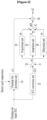
FIG. 3 is a flowchart showing an operation of a BMS according to an embodiment. -
FIG. 4 is a block diagram showing a configuration of a BMS according to an embodiment. -
FIG. 5 is a circuit diagram showing a battery pack according to an embodiment. - An embodiment of the present disclosure may control a charging speed through PID control based on a charging target SOC and a cell voltage in order to prevent a cell from exceeding an upper limit voltage during charging. The PID control applied to an embodiment is a well-known control method, but by being applied to an embodiment, a heterogeneous effect capable of preventing an upper limit voltage exceeding phenomenon of a cell during the charging may be provided. The PID (Proportional-Integral-Differential) control is a form of negative feedback control, which measures an output value of a controlled object, compares it with a reference value based on a control target to calculate an error, and uses a proportional term, an integral term, and a differential term by this error value, so that a control value (hereinafter, a PID value) required to control a control target may be calculated. In an embodiment, the output value may be a cell voltage, the reference value may be an OCV (Open Circuit Voltage) corresponding to the charging target SOC, and the PID value may be a weight value multiplied by a charging speed. The proportional term may be a value proportional to the magnitude of the error value in the current state, the integral term may eliminate a steady-state error, and the differential term may reduce an overshoot and improve stability by braking sudden changes in the output value.
- The charging speed may be expressed as a charging rate (C-rate) hereinafter. The charging rate (C-rate) means a magnitude of a charging current ([A]) or a discharging current ([A]) for a rated capacity of the battery when charging or discharging, and "C" is used for the "unit" of the C-rate. This is expressed as
Equation 1 below. As seen fromEquation 1, the unit of the rated capacity of the battery is not considered in the C-rate.
- Hereinafter, an embodiment disclosed in the present specification will be described in detail with reference to the accompanying drawings, and the same or similar constituent factors are denoted by the same reference numeral regardless of a reference numeral, and a repeated description thereof will be omitted. Suffixes, "module" and and/or "unit" for a constituent factor used for the description below are given or mixed in consideration of only easiness of the writing of the specification, and the suffixes themselves do not have a discriminated meaning or role. Further, in describing the embodiments disclosed in the present disclosure, when it is determined that detailed descriptions relating to well-known functions or configurations may make the subject matter of the embodiments disclosed in the present disclosure unnecessarily ambiguous, the detailed description will be omitted. Further, the accompanying drawings are provided for helping to easily understand embodiments disclosed in the present specification, and the technical spirit disclosed in the present specification is not limited by the accompanying drawings, and it will be appreciated that the present invention includes all of modifications, equivalent matters, and substitutes included in the spirit and the technical scope of the present invention.
- Terms including an ordinary number, such as first and second, are used for describing various constituent factors, but the constituent factors are not limited by the terms. The terms are used only to discriminate one constituent factor from another constituent factor.
- In the present application, it will be appreciated that terms "including" and "having" are intended to designate the existence of characteristics, numbers, steps, operations, constituent factors, and components described in the specification or a combination thereof, and do not exclude a possibility of the existence or addition of one or more other characteristics, numbers, steps, operations, constituent factors, and components, or a combination thereof in advance.
- A program implemented as a set of instructions embodying a control algorithm necessary to control another configuration may be installed in a configuration for controlling another configuration under a specific control condition among configurations according to an embodiment. The control configuration may process input data and stored data, based on the installed program to generate output data. The control configuration may include a nonvolatile memory storing the program and a memory storing the data.
- Hereinafter, a charging control method of a battery pack and a battery system using the same according to an embodiment will be described with reference to drawings.
-
FIG. 1 is a view showing a battery system according to an embodiment. - As shown in
FIG. 1 , abattery system 1 is connected to apower converter 2. - The
power converter 2 may supply power supplied from thebattery pack 10 by the discharge of thebattery pack 10 to an external load (e.g., a motor that provides driving power to an electric vehicle). Electric vehicles include vehicles driven only by a motor without an internal combustion engine and hybrid vehicles that include both an internal combustion engine and a motor. - The
power converter 2 may supply the power for charging thebattery pack 10 from an external commercial power source. Thepower converter 2 may be a charging and discharging device for testing battery performance like a CYCLER. As such, thepower converter 2 may be a device that transfers the power from thebattery pack 10 to the outside or from the outside to thebattery pack 10 according to the discharging or charging of thebattery pack 10. - The
battery system 1 includes abattery pack 10, aBMS 20, and first andsecond contactors - The
first contactor 101 is connected between a positive electrode (P+) of thebattery pack 10 and the power converter 40, and is switched under the control of theBMS 20. Thesecond contactor 102 is connected between the negative electrode (P-) of thebattery pack 10 and thepower converter 2, and is switched under the control of theBMS 20. TheBMS 20 may generate and supply switching signals SC1 and SC2 that control the switching operations of the first andsecond contactors second contactors - The
battery pack 10 includes a plurality of battery cells 10_1 to 10_n (n is two or more natural numbers) connected in series. - The
BMS 20 is connected to both terminals of each of a plurality of battery cells 10_1 to 10_n. TheBMS 20 may measure the cell voltage of each of a plurality of battery cells 10_1 to 10_n at each monitoring period, and may measure the current (hereinafter, a battery pack current) and temperature (hereinafter, a battery pack temperature) of thebattery pack 10. The temperature of a plurality of battery cells 10_1 to 10_n may follow the battery pack temperature. However, the disclosure is not limited thereto, and a plurality of temperature sensors may be disposed in thebattery pack 10, and theBMS 20 may estimate the temperature for each of a plurality of battery cells 10_1 to 10_n based on temperature information obtained from a plurality of temperature sensors. Hereinafter, in the description, the battery pack temperature may be replaced with the battery cell temperature. - The
current sensor 21 may measure the battery pack current IB and transmit the information about the measured battery pack current to theBMS 20. - The
temperature sensor 22 may measure the battery pack temperature and transmit the information about the measured battery pack temperature to theBMS 20. - The
BMS 20 may control and perform cell balancing for a plurality of battery cells 10_1 to 10_n based on a plurality of cell voltages. TheBMS 20 may estimate an SOC (State of Charge), an SOH (State of Health), an SOP (State of Power), etc. based on a plurality of cell voltages of a plurality of battery cells 10_1 to 10_n and the measured information (the battery pack current, the battery pack temperature, etc.) of thebattery pack 10. - The
BMS 20 may determine a charging rate based on the charging target SOC for thebattery pack 10, a plurality of cell voltages, and the battery pack temperature. The charging target SOC may be transmitted to theBMS 20 through CAN communication from an electronic control circuit that controls the electric vehicle when thebattery system 1 is installed in the electric vehicle. Alternatively, the user may transmit the charging target SOC to theBMS 20 through the interface for the battery performance test. - The
BMS 20 may include a map (hereinafter, a charging rate map) in which the charging rate is set based on the charging target SOC and the battery pack temperature. In the charging rate map, a charging rate according to each of a plurality of battery pack temperatures is defined for each of a plurality of charging targets SOC. TheBMS 20 may derive a target OCV corresponding to the charging target SOC. TheBMS 20 generates an error voltage, which is the difference between the target OCV and one of a plurality of cell voltages, for each monitoring period, derives a PID value based on the error voltage for each monitoring period, and multiplies the derived PID value by the charging rate determined based on the charging target SOC and the battery pack temperature to generate a compensating charging rate. - The
BMS 20 transmits the compensation charging rate to thepower converter 2. Thepower converter 2 may supply the power to thebattery pack 10 according to the compensation charging rate. TheBMS 20 may repeat the PID value derivation and the compensation charging rate generation described above for each monitoring period. -
FIG. 2 is a block diagram showing some components of a BMS according to an embodiment. -
FIG. 3 is a flowchart showing an operation of a BMS according to an embodiment. -
FIG. 2 shows, as configurations of theBMS 20, only configurations necessary to generate the compensation charging rate by deriving the PID value. - The
BMS 20 may include a chargingrate derivation unit 21, anOCV conversion unit 22, asubtraction unit 23, aproportional unit 24, anintegration unit 25, adifferential unit 26, a summingunit 27, and amultiplication unit 28. Each of thecomponents 21 to 28 constituting theBMS 20 is a module to perform a corresponding function, and a program including control instructions for performing the corresponding function may be installed in the corresponding module. Each of the chargingrate derivation unit 21, theOCV conversion unit 22, thesubtraction unit 23, theproportional unit 24, theintegration unit 25, thedifferential unit 26, the summingunit 27, and themultiplication unit 28 may operate according to the installed program and generate the output according to the input. - The charging
rate derivation unit 21 stores the charging rate map. The chargingrate derivation unit 21 receives the charging target SOC and the battery pack temperature, and derives the charging rate cr1 from the charging rate map based on the charging target SOC and the battery pack temperature (S1). - The
OCV conversion unit 22 includes a program that implements a SOC to OCV conversion function, and upon receiving the charging target SOC, it may generate the OCV corresponding to the charging target SOC using the program (S2). - The
subtraction unit 23 may generate an error voltage ve by subtracting the cell voltage vc from the OCV (S3). The cell voltage vc may be a cell voltage (hereinafter, a highest cell voltage) that is highest among a plurality of cell voltages. There may be a difference between a plurality of cell voltages, and when the PID value is derived based on the lower cell voltage than the highest cell voltage among a plurality of cell voltages, overcharging may occur for the cell having the highest cell voltage. This may cause the cell voltage of the corresponding cell to become the overvoltage. - The
proportional unit 24, theintegration unit 25, and thedifferential unit 26 for deriving the PID value may receive the error voltage ve for each monitoring period. The proportional parameter, the integral parameter, and the differential parameter for deriving the PID value may be set through tuning using an experimental method. - The
proportional unit 24 multiplies the error voltage ve by a predetermined proportional parameter to generate a proportional value pv (S4). - The
integration unit 25 multiplies the result of integrating the error voltage ve with respect to time by the integration parameter to generate an integral value iv (S5). In this case, the integration period may be a period between the previous monitoring time point and the current monitoring time point, that is, a monitoring cycle. That is, theintegration unit 25 may generate an integral value iv by multiplying an integral parameter by the result obtained by multiplying the error voltage ve by the monitoring cycle. - The
differential unit 26 generates a differential value dv by multiplying the differential parameter by the result of differentiating the error voltage ve with respect to time (S6). At this time, the differential period may also be a monitoring cycle. That is, thedifferential unit 26 may generate a differential value dv by multiplying a value obtained by dividing a value obtained by subtracting the error voltage at the previous monitoring time point from the error voltage ve at the current monitoring time point by a monitoring cycle by a differential parameter. - The summing
unit 27 generates the PID value by summing the proportional value pv, the integral value iv, and the differential value dv (S7). - The
multiplication unit 28 multiplies the charging rate cr1 by the PID value to generate the compensation charging rate cr2 (S8). - The
BMS 20 may transmit the compensation charging rate cr2 to thepower converter 2, and thepower converter 2 may charge thebattery pack 10 with a charging current depending on the compensation charging rate cr2. - The
BMS 20 may perform the above-described operation by measuring the cell voltages of a plurality of battery cells 10_1 to 10_n in the next monitoring cycle and deriving the highest cell voltage among a plurality of cell voltages. In this way, theBMS 20 may generate the compensation charging rate based on the highest cell voltage for each monitoring cycle. However, the present invention is not limited thereto, and the compensation charging rate may be generated for every predetermined integer multiple of the monitoring cycle. -
FIG. 4 is a block diagram showing a configuration of a BMS according to an embodiment. -
FIG. 5 is a circuit diagram showing a battery pack according to an embodiment. - Among the contents shown in
FIG. 4 , the contents overlapping with those shown inFIG. 2 are omitted. - As shown in
FIG. 4 , theBMS 20 further includes amodulator 29 compared to the preceding embodiment. Themodulator 29 may modulate the compensation charging rate according to the structure of a plurality of battery cells constituting thebattery pack 10. - For example,
FIG. 1 shows that a plurality of battery cells 10_1 to 10_n are connected in series, but the battery pack 10' shown inFIG. 5 may include the battery cells connected in parallel to each of a plurality of battery cells 10_1 to 10_n. One of a plurality of battery cells 10_1 to 10_n and one of a plurality of battery cells 11_1 to 11_n are connected in parallel to form a battery cell group, and the plurality of battery cell groups that are connected in parallel are connected in series.FIG. 5 is an example of a case where battery cell groups in which battery cells are connected in parallel with p are connected in series with s (p and s are natural numbers of 2 or more). - In the battery pack 10' shown in
FIG. 5 , since two battery cells are connected in parallel, the charging current is divided into two paths and flows to each cell. Therefore, the compensation charging rate should be doubled. Themodulator 29 may generate a modulation charging rate cr3 obtained by multiplying the compensation charging rate cr2 by a proportional constant 2 considering two current paths in parallel. Themodulator 29 may determine a proportional constant value according to the number of battery cells connected in parallel, that is, p. For example, when the number of battery cells connected in parallel is 3, the proportional constant may be 3. - The
BMS 20 may transmits the modulated charging rate cr3 to thepower converter 2, and thepower converter 2 may charge thebattery pack 10 with the charging current according to the modulated charging rate cr3. - The conventional rapid charging method proceeds with the charging at a constant C-Rate, but reduces the current when the cell voltage exceeds the upper limit voltage. In contrast, the charging method according to an embodiment converts the charging target SOC to the OCV, sets the upper limit voltage in the charging for the charging target SOC, and controls the PID based on the error voltage between a plurality of battery cell voltages and the OCV, thereby it is possible to prevent the cell voltage from exceeding the upper limit voltage.
- While this invention has been described in connection with what is presently considered to be practical embodiments, it is to be understood that the invention is not limited to the disclosed embodiments. On the contrary, it is intended to cover various modifications and equivalent arrangements included within the spirit and scope of the appended claims.
Claims (13)
- A battery system comprising:a battery pack including a plurality of battery cells; anda battery management system configured to derive a charging rate based on a charging target SOC (State of Charge) for the battery pack and the battery pack temperature, compensate the charging rate through PID control based on an error voltage between any one of the plurality of cell voltages and an open circuit voltage (OCV) corresponding to the charging target SOC to generate a compensation charging rate.
- The battery system of claim 1, wherein
the battery management system is configured to generate a proportional value, an integral value, and a differential value based on the error voltage to derive a PID value, and multiply the charging rate by the PID value to generate the compensation charging rate. - The battery system of claim 2, wherein
the battery management system is configured to derive the PID value by adding the proportional value, the integral value, and the differential value. - The battery system of claim 1, whereinthe battery management system includes a charging rate map in which a charging rate corresponding to each temperature of a plurality of battery packs is defined for each of a plurality of charging targets SOCs, andis configured to receive the charging target SOCs and the battery pack temperature, and derive the charging rate corresponding to the received charging target SOCs and battery pack temperature from the charging rate map.
- The battery system of claim 1, wherein
the battery management system is configured to generate the OCV corresponding to the charging target SOC by using an SOC to OCV conversion function. - The battery system of claim 1, wherein
the battery management system is configured to generate the error voltage by subtracting the highest cell voltage among the plurality of cell voltages from the OCV. - The battery system of claim 1, whereinin the plurality of battery cells, when battery cell groups in which battery cells are connected in parallel with p are connected in series with s,the battery management system is configured to generate a modulation charging rate by multiplying the compensation charging rate by p.
- A charging control method of a battery pack including a plurality of battery cells controlled by a battery management system, comprising:deriving a charging rate based on a charging target State of Charge (SOC) for the battery pack and a battery pack temperature;generating an error voltage between any one of the plurality of cell voltages and an open circuit voltage (OCV) corresponding to the charging target SOC; andgenerating a compensation charging rate by compensating for the charging rate through PID control based on the error voltage.
- The charging control method of the battery pack of claim 8, wherein
the generating of the compensation charging rate includes:generating a proportional value, an integral value, and a differential value based on the error voltage;deriving a PID value by adding the proportional value, the integral value, and the differential value; andmultiplying the charging rate by the PID value to generate the compensation charging rate. - The charging control method of the battery pack of claim 8, wherein
the deriving of the charging rate includes:receiving the charging target SOC and the battery pack temperature; andderiving the charging rate corresponding to the received charging target SOC and battery pack temperature from a charging rate map. - The charging control method of the battery pack of claim 8, further comprising
generating the OCV corresponding to the charging target SOC by using an SOC to OCV conversion function. - The charging control method of the battery pack of claim 8, wherein
the generating of the error voltage includes
generating the error voltage by subtracting the highest cell voltage among the plurality of cell voltages from the OCV. - The charging control method of the battery pack of claim 8, further comprising,in the plurality of battery cells, when battery cell groups in which battery cells are connected in parallel with p are connected in series with s,generating a modulation charging rate by multiplying the compensation charging rate by p.
Applications Claiming Priority (2)
| Application Number | Priority Date | Filing Date | Title |
|---|---|---|---|
| KR1020220002136A KR20230106347A (en) | 2022-01-06 | 2022-01-06 | Charging control method of battery pack and battery system using the same |
| PCT/KR2022/021601 WO2023132563A1 (en) | 2022-01-06 | 2022-12-29 | Charging control method for battery pack, and battery system using same |
Publications (3)
| Publication Number | Publication Date |
|---|---|
| EP4336621A1 true EP4336621A1 (en) | 2024-03-13 |
| EP4336621A4 EP4336621A4 (en) | 2025-01-08 |
| EP4336621B1 EP4336621B1 (en) | 2026-04-08 |
Family
ID=87073815
Family Applications (1)
| Application Number | Title | Priority Date | Filing Date |
|---|---|---|---|
| EP22919100.2A Active EP4336621B1 (en) | 2022-01-06 | 2022-12-29 | Charging control method of battery pack and battery system using the same |
Country Status (6)
| Country | Link |
|---|---|
| US (1) | US20240283273A1 (en) |
| EP (1) | EP4336621B1 (en) |
| JP (1) | JP7585599B2 (en) |
| KR (1) | KR20230106347A (en) |
| CN (1) | CN117355976A (en) |
| WO (1) | WO2023132563A1 (en) |
Families Citing this family (1)
| Publication number | Priority date | Publication date | Assignee | Title |
|---|---|---|---|---|
| US20240388111A1 (en) * | 2023-05-15 | 2024-11-21 | Lenovo (Singapore) Pte. Ltd. | Battery Charge Controller |
Family Cites Families (14)
| Publication number | Priority date | Publication date | Assignee | Title |
|---|---|---|---|---|
| US8163410B2 (en) * | 2007-09-14 | 2012-04-24 | A123 Systems, Inc. | Lithium rechargeable cell with reference electrode for state of health monitoring |
| JP5098912B2 (en) * | 2008-07-11 | 2012-12-12 | ソニー株式会社 | Battery pack and charge control system |
| JP5393619B2 (en) * | 2010-08-26 | 2014-01-22 | カルソニックカンセイ株式会社 | Battery charge rate estimation device |
| JP2012200781A (en) | 2011-03-28 | 2012-10-22 | Nippon Avionics Co Ltd | Charge control method for electrostatic energy storage welding power source and electrostatic energy storage welding power source |
| JP2013130448A (en) * | 2011-12-21 | 2013-07-04 | Panasonic Corp | Charging/discharging system and battery pack |
| WO2016113791A1 (en) | 2015-01-16 | 2016-07-21 | ソニー株式会社 | Cell device, charging control device, and charging control method |
| EP3242373B1 (en) | 2016-03-01 | 2020-01-08 | Guangdong Oppo Mobile Telecommunications Corp., Ltd. | Charging method, adapter, mobile terminal and charging system |
| KR102695516B1 (en) * | 2016-11-18 | 2024-08-14 | 삼성전자주식회사 | Battery charging method, battery charging information generating method and battery charging apparatus |
| KR102082381B1 (en) * | 2016-11-24 | 2020-02-27 | 주식회사 엘지화학 | Battery charge control algorithm |
| CN110945738B (en) * | 2017-07-31 | 2023-04-28 | 日产自动车株式会社 | Charging time calculation method and charging control device |
| JP7213698B2 (en) * | 2019-01-22 | 2023-01-27 | サンデン株式会社 | VEHICLE BATTERY TEMPERATURE ADJUSTMENT DEVICE AND VEHICLE AIR CONDITIONER WITH SAME |
| WO2020166087A1 (en) | 2019-02-15 | 2020-08-20 | 株式会社日立製作所 | Charge-discharge control system and charge-discharge control method |
| KR102731551B1 (en) * | 2019-03-04 | 2024-11-18 | 현대자동차주식회사 | System and method for controlling battery charging or discharging |
| CN112234661B (en) * | 2020-04-30 | 2022-03-29 | 蜂巢能源科技有限公司 | Method for determining optimal charging parameter of battery, charging management method and system |
-
2022
- 2022-01-06 KR KR1020220002136A patent/KR20230106347A/en active Pending
- 2022-12-29 EP EP22919100.2A patent/EP4336621B1/en active Active
- 2022-12-29 WO PCT/KR2022/021601 patent/WO2023132563A1/en not_active Ceased
- 2022-12-29 US US18/563,732 patent/US20240283273A1/en active Pending
- 2022-12-29 CN CN202280036895.7A patent/CN117355976A/en active Pending
- 2022-12-29 JP JP2023565475A patent/JP7585599B2/en active Active
Also Published As
| Publication number | Publication date |
|---|---|
| US20240283273A1 (en) | 2024-08-22 |
| JP2024517687A (en) | 2024-04-23 |
| EP4336621B1 (en) | 2026-04-08 |
| CN117355976A (en) | 2024-01-05 |
| KR20230106347A (en) | 2023-07-13 |
| WO2023132563A1 (en) | 2023-07-13 |
| EP4336621A4 (en) | 2025-01-08 |
| JP7585599B2 (en) | 2024-11-19 |
Similar Documents
| Publication | Publication Date | Title |
|---|---|---|
| Tanim et al. | Fast charge implications: Pack and cell analysis and comparison | |
| EP1798100B1 (en) | Battery management system | |
| US6356083B1 (en) | State of charge algorithm for a battery | |
| US9205750B2 (en) | Method to estimate battery open-circuit voltage based on transient resistive effects | |
| EP2720343B1 (en) | Battery control device and battery system | |
| EP1801605B1 (en) | Method for compensating state of charge of a battery and battery management system using the same | |
| US6127806A (en) | State of charge indicator | |
| US6646419B1 (en) | State of charge algorithm for lead-acid battery in a hybrid electric vehicle | |
| JP5715694B2 (en) | Battery control device, battery system | |
| US10124696B2 (en) | Estimation and compensation of battery measurement and asynchronization biases | |
| EP3410558A1 (en) | Battery control device | |
| US9680320B2 (en) | Battery control apparatus | |
| EP3089256A1 (en) | Temperature control apparatus for electricity storage device | |
| EP3664247A1 (en) | Charging time computation method and charge control device | |
| EP2328256A2 (en) | Equalization device, equalization processing program, battery system, electric vehicle and equalization processing method | |
| US8008893B2 (en) | Battery analysis system | |
| US9197078B2 (en) | Battery parameter estimation | |
| EP2720054A1 (en) | Battery control device and battery system | |
| CN115706442B (en) | Battery management device and method | |
| US20190043674A1 (en) | Electric power storage apparatus | |
| EP4336621B1 (en) | Charging control method of battery pack and battery system using the same | |
| Jadhav et al. | Development of IoT based battery management system for EV | |
| EP4507162A1 (en) | Battery control device and battery system | |
| EP4333253A1 (en) | Battery control method | |
| CN120171320A (en) | Active Battery State of Charge Balancing |
Legal Events
| Date | Code | Title | Description |
|---|---|---|---|
| STAA | Information on the status of an ep patent application or granted ep patent |
Free format text: STATUS: THE INTERNATIONAL PUBLICATION HAS BEEN MADE |
|
| PUAI | Public reference made under article 153(3) epc to a published international application that has entered the european phase |
Free format text: ORIGINAL CODE: 0009012 |
|
| STAA | Information on the status of an ep patent application or granted ep patent |
Free format text: STATUS: REQUEST FOR EXAMINATION WAS MADE |
|
| 17P | Request for examination filed |
Effective date: 20231207 |
|
| AK | Designated contracting states |
Kind code of ref document: A1 Designated state(s): AL AT BE BG CH CY CZ DE DK EE ES FI FR GB GR HR HU IE IS IT LI LT LU LV MC ME MK MT NL NO PL PT RO RS SE SI SK SM TR |
|
| A4 | Supplementary search report drawn up and despatched |
Effective date: 20241209 |
|
| RIC1 | Information provided on ipc code assigned before grant |
Ipc: H01M 10/48 20060101ALI20241203BHEP Ipc: G05B 11/42 20060101ALI20241203BHEP Ipc: H02J 7/00 20060101ALI20241203BHEP Ipc: H01M 10/42 20060101ALI20241203BHEP Ipc: H01M 10/44 20060101AFI20241203BHEP |
|
| DAV | Request for validation of the european patent (deleted) | ||
| DAX | Request for extension of the european patent (deleted) | ||
| GRAP | Despatch of communication of intention to grant a patent |
Free format text: ORIGINAL CODE: EPIDOSNIGR1 |
|
| STAA | Information on the status of an ep patent application or granted ep patent |
Free format text: STATUS: GRANT OF PATENT IS INTENDED |
|
| INTG | Intention to grant announced |
Effective date: 20251219 |
|
| P01 | Opt-out of the competence of the unified patent court (upc) registered |
Free format text: CASE NUMBER: UPC_APP_0000274_4336621/2026 Effective date: 20260106 |
|
| GRAS | Grant fee paid |
Free format text: ORIGINAL CODE: EPIDOSNIGR3 |
|
| GRAA | (expected) grant |
Free format text: ORIGINAL CODE: 0009210 |
|
| STAA | Information on the status of an ep patent application or granted ep patent |
Free format text: STATUS: THE PATENT HAS BEEN GRANTED |
|
| AK | Designated contracting states |
Kind code of ref document: B1 Designated state(s): AL AT BE BG CH CY CZ DE DK EE ES FI FR GB GR HR HU IE IS IT LI LT LU LV MC ME MK MT NL NO PL PT RO RS SE SI SK SM TR |
|
| REG | Reference to a national code |
Ref country code: CH Ref legal event code: F10 Free format text: ST27 STATUS EVENT CODE: U-0-0-F10-F00 (AS PROVIDED BY THE NATIONAL OFFICE) Effective date: 20260408 Ref country code: GB Ref legal event code: FG4D |
|
| REG | Reference to a national code |
Ref country code: DE Ref legal event code: R096 Ref document number: 602022034363 Country of ref document: DE |