EP4336342A2 - Processor, image processing device, glasses-type information display device, image processing method, and image processing program - Google Patents
Processor, image processing device, glasses-type information display device, image processing method, and image processing program Download PDFInfo
- Publication number
- EP4336342A2 EP4336342A2 EP23196665.6A EP23196665A EP4336342A2 EP 4336342 A2 EP4336342 A2 EP 4336342A2 EP 23196665 A EP23196665 A EP 23196665A EP 4336342 A2 EP4336342 A2 EP 4336342A2
- Authority
- EP
- European Patent Office
- Prior art keywords
- display
- change
- image
- display image
- processor
- Prior art date
- Legal status (The legal status is an assumption and is not a legal conclusion. Google has not performed a legal analysis and makes no representation as to the accuracy of the status listed.)
- Pending
Links
Images




Classifications
-
- G—PHYSICS
- G06—COMPUTING OR CALCULATING; COUNTING
- G06F—ELECTRIC DIGITAL DATA PROCESSING
- G06F3/00—Input arrangements for transferring data to be processed into a form capable of being handled by the computer; Output arrangements for transferring data from processing unit to output unit, e.g. interface arrangements
- G06F3/14—Digital output to display device ; Cooperation and interconnection of the display device with other functional units
-
- G—PHYSICS
- G06—COMPUTING OR CALCULATING; COUNTING
- G06F—ELECTRIC DIGITAL DATA PROCESSING
- G06F3/00—Input arrangements for transferring data to be processed into a form capable of being handled by the computer; Output arrangements for transferring data from processing unit to output unit, e.g. interface arrangements
- G06F3/01—Input arrangements or combined input and output arrangements for interaction between user and computer
- G06F3/011—Arrangements for interaction with the human body, e.g. for user immersion in virtual reality
-
- G—PHYSICS
- G06—COMPUTING OR CALCULATING; COUNTING
- G06F—ELECTRIC DIGITAL DATA PROCESSING
- G06F3/00—Input arrangements for transferring data to be processed into a form capable of being handled by the computer; Output arrangements for transferring data from processing unit to output unit, e.g. interface arrangements
- G06F3/14—Digital output to display device ; Cooperation and interconnection of the display device with other functional units
- G06F3/147—Digital output to display device ; Cooperation and interconnection of the display device with other functional units using display panels
-
- G—PHYSICS
- G02—OPTICS
- G02B—OPTICAL ELEMENTS, SYSTEMS OR APPARATUS
- G02B27/00—Optical systems or apparatus not provided for by any of the groups G02B1/00 - G02B26/00, G02B30/00
- G02B27/0093—Optical systems or apparatus not provided for by any of the groups G02B1/00 - G02B26/00, G02B30/00 with means for monitoring data relating to the user, e.g. head-tracking, eye-tracking
-
- G—PHYSICS
- G02—OPTICS
- G02B—OPTICAL ELEMENTS, SYSTEMS OR APPARATUS
- G02B27/00—Optical systems or apparatus not provided for by any of the groups G02B1/00 - G02B26/00, G02B30/00
- G02B27/01—Head-up displays
- G02B27/017—Head mounted
- G02B27/0172—Head mounted characterised by optical features
-
- G—PHYSICS
- G06—COMPUTING OR CALCULATING; COUNTING
- G06T—IMAGE DATA PROCESSING OR GENERATION, IN GENERAL
- G06T19/00—Manipulating three-dimensional [3D] models or images for computer graphics
- G06T19/006—Mixed reality
-
- G—PHYSICS
- G09—EDUCATION; CRYPTOGRAPHY; DISPLAY; ADVERTISING; SEALS
- G09G—ARRANGEMENTS OR CIRCUITS FOR CONTROL OF INDICATING DEVICES USING STATIC MEANS TO PRESENT VARIABLE INFORMATION
- G09G5/00—Control arrangements or circuits for visual indicators common to cathode-ray tube indicators and other visual indicators
- G09G5/36—Control arrangements or circuits for visual indicators common to cathode-ray tube indicators and other visual indicators characterised by the display of a graphic pattern, e.g. using an all-points-addressable [APA] memory
- G09G5/37—Details of the operation on graphic patterns
- G09G5/377—Details of the operation on graphic patterns for mixing or overlaying two or more graphic patterns
-
- G—PHYSICS
- G09—EDUCATION; CRYPTOGRAPHY; DISPLAY; ADVERTISING; SEALS
- G09G—ARRANGEMENTS OR CIRCUITS FOR CONTROL OF INDICATING DEVICES USING STATIC MEANS TO PRESENT VARIABLE INFORMATION
- G09G5/00—Control arrangements or circuits for visual indicators common to cathode-ray tube indicators and other visual indicators
- G09G5/36—Control arrangements or circuits for visual indicators common to cathode-ray tube indicators and other visual indicators characterised by the display of a graphic pattern, e.g. using an all-points-addressable [APA] memory
- G09G5/38—Control arrangements or circuits for visual indicators common to cathode-ray tube indicators and other visual indicators characterised by the display of a graphic pattern, e.g. using an all-points-addressable [APA] memory with means for controlling the display position
-
- G—PHYSICS
- G02—OPTICS
- G02B—OPTICAL ELEMENTS, SYSTEMS OR APPARATUS
- G02B27/00—Optical systems or apparatus not provided for by any of the groups G02B1/00 - G02B26/00, G02B30/00
- G02B27/01—Head-up displays
- G02B27/017—Head mounted
- G02B2027/0178—Eyeglass type
-
- G—PHYSICS
- G02—OPTICS
- G02B—OPTICAL ELEMENTS, SYSTEMS OR APPARATUS
- G02B27/00—Optical systems or apparatus not provided for by any of the groups G02B1/00 - G02B26/00, G02B30/00
- G02B27/01—Head-up displays
- G02B27/0179—Display position adjusting means not related to the information to be displayed
- G02B2027/0187—Display position adjusting means not related to the information to be displayed slaved to motion of at least a part of the body of the user, e.g. head, eye
-
- G—PHYSICS
- G06—COMPUTING OR CALCULATING; COUNTING
- G06F—ELECTRIC DIGITAL DATA PROCESSING
- G06F2203/00—Indexing scheme relating to G06F3/00 - G06F3/048
- G06F2203/01—Indexing scheme relating to G06F3/01
- G06F2203/012—Walk-in-place systems for allowing a user to walk in a virtual environment while constraining him to a given position in the physical environment
-
- G—PHYSICS
- G06—COMPUTING OR CALCULATING; COUNTING
- G06T—IMAGE DATA PROCESSING OR GENERATION, IN GENERAL
- G06T2200/00—Indexing scheme for image data processing or generation, in general
- G06T2200/04—Indexing scheme for image data processing or generation, in general involving 3D image data
-
- G—PHYSICS
- G09—EDUCATION; CRYPTOGRAPHY; DISPLAY; ADVERTISING; SEALS
- G09G—ARRANGEMENTS OR CIRCUITS FOR CONTROL OF INDICATING DEVICES USING STATIC MEANS TO PRESENT VARIABLE INFORMATION
- G09G2320/00—Control of display operating conditions
- G09G2320/02—Improving the quality of display appearance
- G09G2320/0261—Improving the quality of display appearance in the context of movement of objects on the screen or movement of the observer relative to the screen
-
- G—PHYSICS
- G09—EDUCATION; CRYPTOGRAPHY; DISPLAY; ADVERTISING; SEALS
- G09G—ARRANGEMENTS OR CIRCUITS FOR CONTROL OF INDICATING DEVICES USING STATIC MEANS TO PRESENT VARIABLE INFORMATION
- G09G2340/00—Aspects of display data processing
- G09G2340/04—Changes in size, position or resolution of an image
- G09G2340/0464—Positioning
-
- G—PHYSICS
- G09—EDUCATION; CRYPTOGRAPHY; DISPLAY; ADVERTISING; SEALS
- G09G—ARRANGEMENTS OR CIRCUITS FOR CONTROL OF INDICATING DEVICES USING STATIC MEANS TO PRESENT VARIABLE INFORMATION
- G09G2340/00—Aspects of display data processing
- G09G2340/14—Solving problems related to the presentation of information to be displayed
- G09G2340/145—Solving problems related to the presentation of information to be displayed related to small screens
-
- G—PHYSICS
- G09—EDUCATION; CRYPTOGRAPHY; DISPLAY; ADVERTISING; SEALS
- G09G—ARRANGEMENTS OR CIRCUITS FOR CONTROL OF INDICATING DEVICES USING STATIC MEANS TO PRESENT VARIABLE INFORMATION
- G09G2354/00—Aspects of interface with display user
Definitions
- the present disclosure relates to a processor, an image processing device, a glasses-type information display device, an image processing method, and a non-transitory storage medium storing an image processing program.
- a transmissive display device such as an augmented reality (AR) device that displays a state in which images are superimposed in a real space is known in the related art as a display device that displays a three-dimensional video.
- AR augmented reality
- the display image in a case in which the position of the display image is changed for image stabilization, the display image may not be displayed appropriately, for example, the display image may not be displayed.
- the present disclosure has been made in view of the above circumstances, and an object of the present disclosure is to provide a processor, an image processing device, a glasses-type information display device, an image processing method, and a non-transitory storage medium storing an image processing program capable of performing image stabilization for an appropriate display position of a display image.
- a processor of a first aspect of the present disclosure is configured to, based on a change of a relative position between a transmissive display device and a user's eye, derive a second position according to a first position of a display image displayed in a display region of the display device and the change of the relative position, change the first position to the second position in a case in which the second position does not exceed a correction region where a correction of a display position is possible, and change the first position to a third position and display the display image within the correction region in a case in which the second position exceeds the correction region.
- the processor is configured to change a position of the display region with respect to the correction region according to the change of the relative position.
- the processor in the processor of the second aspect, is configured to independently correct display positions of the plurality of display images, in a case in which a plurality of the display images are displayed in the display region.
- the processor is configured to perform a control to change a display position of the second display image according to the first display image after changing the display position to the third position, in a case in which a first display image is superimposed on a second display image by changing a display position of the first display image to the third position.
- the processor is configured to selectively perform any of a first control to change a display position of the second display image according to the first display image after changing the display position to the third position, a second control to superimpose and display the first display image and the second display image, or a third control to set the display position of the first display image to the second position, in a case in which a first display image is superimposed on a second display image by changing a display position of the first display image to the third position.
- a displayable range in which the display of the display image is possible is predetermined according to a degree of the change of the relative position, and the processor is configured to change the display position of the display image to within the displayable range.
- the processor is configured to select the displayable range according to a motion state of the user, and changes the display position of the display image to within the selected displayable range.
- the processor is configured to perform a control to hide the display image instead of changing the first position to the third position, in a case in which a change amount of the relative position exceeds a predetermined threshold value.
- the display image is divided into a plurality of partial regions, and the third position is a position where at least a predetermined partial region among the plurality of partial regions is within the correction region.
- a priority according to an area within the correction region is given to the display image, and the processor is configured to change the second position to the third position based on the priority, in a case in which the second position exceeds the correction region.
- a case in which the second position exceeds the correction region where the correction of the display position is possible is a case in which at least a part of the display image is outside the correction region.
- a case in which the second position exceeds the correction region where the correction of the display position is possible is a case in which 90% or more of an area of the display image is outside the correction region.
- an image processing device of a further aspect of the present disclosure comprises a processor configured to, based on a change of a relative position between a transmissive display device and a user's eye, derive a second position according to a first position of a display image displayed in a display region of the display device and the change of the relative position, change the first position to the second position in a case in which the second position does not exceed a correction region where a correction of a display position is possible, and change the first position to a third position and display the display image within the correction region in a case in which the second position exceeds the correction region.
- a glasses-type information display device of a further aspect of the present disclosure comprises a transmissive display device and the processor of the present disclosure.
- an image processing method executed by a processor of a further aspect of the present disclosure comprises, based on a change of a relative position between a transmissive display device and a user's eye, deriving a second position according to a first position of a display image displayed in a display region of the display device and the change of the relative position, changing the first position to the second position in a case in which the second position does not exceed a correction region where a correction of a display position is possible, and changing the first position to a third position and displaying the display image within the correction region in a case in which the second position exceeds the correction region.
- a non- transitory storage medium storing an image processing program for causing a processor to execute a process of a further aspect of the present disclosure comprises, based on a change of a relative position between a transmissive display device and a user's eye, deriving a second position according to a first position of a display image displayed in a display region of the display device and the change of the relative position, changing the first position to the second position in a case in which the second position does not exceed a correction region where a correction of a display position is possible, and changing the first position to a third position and displaying the display image within the correction region in a case in which the second position exceeds the correction region.
- the glasses-type information display device 1 comprises augmented reality (AR) glasses 10 and a smartphone 12.
- AR augmented reality
- the AR glasses 10 are a device that allows a user to visually recognize a projection image, which is projected from an organic light emitting diode (OLED) 26, in a state in which the projection image is superimposed on a real image.
- Fig. 2 is a perspective view of an example of the AR glasses 10 of the present embodiment. As shown in Figs. 1 and 2 , the AR glasses 10 comprise a pair of a transmission unit 20L for a left eye and a transmission unit 20R for a right eye, an OLED 26, and vibration detection sensor 29.
- the AR glasses 10 of the present embodiment are an example of a transmissive display device of the present disclosure.
- the OLED 26 projects an image (projection image), which represents information, onto the transmission unit 20R for a right eye in order to insert information into the visual field of a real image, which is visually recognized by the user through the transmission unit 20R for a right eye, in a superimposed manner.
- image projection image
- the transmission unit 20R for a right eye includes a lens 22R for a right eye and a light guide plate 24.
- Light corresponding to the projection image projected from the OLED 26 is incident on one end of the light guide plate 24.
- the direction of light propagated through the light guide plate 24 is changed at an emission portion (not shown), and the light is emitted in a direction of the user's eye.
- the light, which is emitted from the light guide plate 24 and corresponds to the projection image, is transmitted through the lens 22R for a right eye, is guided to the right eye of the user, and is visually recognized as a projected image with the right eye.
- the user visually recognizes a real space, which is shown through the lens 22R for a right eye, as a real image with the right eye.
- the visually-recognized image visually recognized with the right eye of the user is in a state in which the projected image according to the projection image projected onto the light guide plate 24 is superimposed on the real image representing the real space shown through the lens 22R for a right eye.
- the visually-recognized image visually recognized by the user is the real image that represents the real space shown through the lens 22R for a right eye and the light guide plate 24.
- the transmission unit 20L for a left eye includes a lens 22L for a left eye.
- the user visually recognizes the real space, which is shown through the lens 22L for a left eye, with the left eye.
- the vibration detection sensor 29 is a sensor that detects a change of a relative position between the AR glasses 10 and the user's eye as vibration of the AR glasses 10. That is, the vibration detection sensor 29 is a sensor that detects so-called "blur". Specifically, in the vibration detection sensor 29 is a sensor that detects a moving direction indicating whether the AR glasses 10 have moved in an in-plane direction of the lens 22R for a right eye, in other words, in a left-right or up-down direction of the user, and the moving amount in the moving direction. The moving direction and the moving amount detected by the vibration detection sensor 29 are output to the smartphone 12 as information indicating vibration.
- the smartphone 12 comprises a processor 41.
- the processor 41 of the present embodiment controls the OLED 26 to project the projection image onto the light guide plate 24 from the OLED 26.
- the processor 41 of the present embodiment performs a control of correcting blurring, that is, a change of a relative position between the AR glasses 10 and the user's eye.
- the smartphone 12 of the present embodiment is an example of an image processing device of the present disclosure.
- Fig. 3 shows a block diagram showing an example of a hardware configuration of the smartphone 12.
- the smartphone 12 comprises a central processing unit (CPU) 40, a memory 42, an interface (I/F) unit 43, a storage unit 44, a display 46, and an input device 48.
- the CPU 40, the memory 42, the I/F unit 43, the storage unit 44, the display 46, and the input device 48 are connected to each other via a bus 49, such as a system bus or a control bus, such that various types of information can be given and received therebetween.
- a bus 49 such as a system bus or a control bus
- the CPU 40 reads out various programs, which include an image processing program 45 stored in the storage unit 44, to the memory 42 and performs processing corresponding to the program read out. Accordingly, the CPU 40 performs a control of the image stabilization and a control of the display of the projected image by the OLED 26.
- the processor 41 of the present embodiment is composed of a combination of the CPU 40 and the image processing program 45.
- the memory 42 is a work memory that is used in a case in which the CPU 40 performs processing.
- the image processing program 45 executed in the CPU 40 is stored in the storage unit 44.
- the image data (not shown) of the projection image projected from the OLED 26, various other types of information, and the like are also stored in the storage unit 44.
- Specific examples of the storage unit 44 include a hard disk drive (HDD), a solid state drive (SSD), and the like.
- the I/F unit 43 communicates various types of information to each of the OLED 26 using wireless communication or wired communication.
- the display 46 and the input device 48 function as a user interface.
- the display 46 provides various types of information, which is related to the projection of the projection image, to a user.
- the display 46 is not particularly limited, and examples of the display 46 include a liquid crystal monitor, a light emitting diode (LED) monitor, and the like.
- the input device 48 is operated by a user so that various instructions related to the projection of the projection image are input.
- the input device 48 is not particularly limited, and examples of the input device 48 include a keyboard, a touch pen, a mouse, and the like.
- a touch panel display in which the display 46 and the input device 48 are integrated with each other is employed in the smartphone 12.
- Fig. 4 shows a functional block diagram showing an example of a configuration related to the function of the processor 41 of the present embodiment.
- the processor 41 comprises an acquisition unit 50, an image stabilization unit 52, and a display controller 54.
- the CPU 40 executes the image processing program 45 stored in the storage unit 44, so that the CPU 40 functions as the acquisition unit 50, the image stabilization unit 52, and the display controller 54.
- the acquisition unit 50 acquires information indicating the vibration from the vibration detection sensor 29 of the AR glasses 10.
- the acquisition unit 50 outputs the acquired information indicating the vibration to the image stabilization unit 52.
- the image stabilization unit 52 of the present embodiment has a function of correcting the display position of the display image to cancel the blur based on the information indicating the vibration. As shown in Fig. 4 , the image stabilization unit 52 includes a display region position change unit 53A and a display image display position change unit 53B. The image stabilization and a change of the display position of the display image by the image stabilization unit 52 will be described with reference to Fig. 5A and Fig. 5B .
- a state in which the user's eye U and the AR glasses 10 are facing each other is defined as an initial state in which no blurring occurs.
- a display region 70 that displays a display image 80 displayed by projecting a projection image from the OLED 26 is provided.
- Fig. 5A shows display images 80Ato 80D as an example of the display image 80.
- the display images 80A to 80D are collectively referred to without distinguishing between them, they are referred to as the display image 80.
- a correction region 72 for correcting the display position of the display image 80 in a case in which blurring occurs is provided.
- a position of the correction region 72 is fixed with respect to the lens 22R for a right eye.
- the maximum region in which the display image 80 can be displayed in the AR glasses 10 is defined as the correction region 72.
- an area of the correction region 72 is greater than an area of the display region 70.
- the display region 70 is provided inside the correction region 72, and in the initial state, center positions of the display region 70 and the correction region 72 are the same.
- Fig. 5B shows a case in which at least one of the downward movement of the user's eye U or the upward movement of the AR glasses 10 occurs as the change of the relative position from the state shown in Fig. 5A .
- the display region position change unit 53A performs image stabilization that changes the position of the display region 70 with respect to the lens 22R for a right eye in a downward direction so as to cancel the change of the relative position.
- the relative position between the user's eye U and the display region 70 does not change from the initial state by changing the position of the display region 70 by the display region position change unit 53A.
- the relative position between the user's eye U and the display position of the display image 80 does not change from the initial state. Therefore, the user can visually recognize the display image 80 as if it is not moving.
- the display region 70 in a case in which the amount of blurring is large, the display region 70, whose position has been changed by the display region position change unit 53A, may exceed the correction region 72 to the outside.
- the display image 80 whose display position is within the display region 70 outside the correction region 72 is not actually displayed on the lens 22R for a right eye and is not visually recognized by the user's eye U.
- the display position of the display image 80A indicated by a dotted line is outside the correction region 72. Therefore, the display image 80A is not actually displayed on the lens 22R for a right eye and is not visually recognized by the user's eye U.
- the display image display position change unit 53B of the present embodiment changes the display position of the display image 80 whose display position is outside the correction region 72 to within the correction region 72.
- the display position of the display image 80A indicated by the dotted line is moved in a direction of an arrow Z, and the display position is changed to within the correction region 72 such that the entire display image 80A is within the correction region 72.
- the display image 80A after changing the display position to within the correction region 72 is indicated by a solid line. In this way, the user can visually recognize the display image 80A by changing the display position of the display image 80A to within the correction region 72.
- the display region position change unit 53A performs basic image stabilization that changes the position of the display region 70 with respect to the lens 22R for a right eye based on the change of the relative position between the AR glasses 10 (lens 22R for a right eye) and the user's eye U.
- the display region position change unit 53A of the present embodiment derives a display position (hereinafter, referred to as a basic correction display position) of the display image 80 according to a display position (hereinafter, referred to as an initial display position) of the display image 80 displayed in the display region 70 in the initial state and the change of the relative position.
- the display image display position change unit 53B changes the display position of the display image 80 to a position within the correction region 72.
- the initial display position of the present embodiment is an example of a first position of the present disclosure.
- the basic correction display position of the display image 80 in a case in which the basic image stabilization is performed in the present embodiment is an example of a second position of the present disclosure.
- the display position of the display image 80 derived by the display image display position change unit 53B of the present embodiment is an example of a third position of the present disclosure.
- the specific state in a case in which the display position of the display image 80 exceeds the correction region 72 is not particularly limited and may be predetermined.
- a case in which at least a part of the display image 80 is outside the correction region 72 in other words, there may be a case in which the display image 80 even slightly reaches outside the correction region 72.
- Fig. 6B there may be a case in which 90% or more of the area of the display image 80 is outside the correction region 72.
- the image stabilization unit 52 outputs the display positions of the display images 80A to 80D derived by the display region position change unit 53A and the display image display position change unit 53B to the display controller 54.
- the display controller 54 has a function of displaying the display images 80A to 80D at the display position input from the image stabilization unit 52. Specifically, the display controller 54 acquires image data of each of the display images 80A to 80D projected by the OLED 26. As an example, in the present embodiment, since the image data of each of the display images 80A to 80D is stored in the storage unit 44, the display controller 54 acquires the image data of each of the display images 80Ato 80D from the storage unit 44. In addition, regardless of the present embodiment, an embodiment in which the image data of each of the display images 80A to 80D may be acquired from an external device of the smartphone 12 via the I/F unit 43 may be used. In the following, the image data of the display images 80A to 80D will be simply referred to as display images, and for example, acquiring the display image 80A is referred to as acquiring the display image.
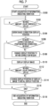
- FIG. 7 shows a flowchart showing an example of the flow of image processing that is performed by the processor 41 of the smartphone 12 of the present embodiment.
- the processor 41 of the present embodiment in a case in which the projection of the projection image by the OLED 26 is started and the display of the display image 80 is started, the image processing shown as an example in Fig. 7 is executed.
- Step S100 of Fig. 7 the acquisition unit 50 starts acquisition of information indicating vibration as described above. Specifically, the acquisition of the information indicating the vibration output from the vibration detection sensor 29 is started.
- the display region position change unit 53A determines whether or not the moving amount of the AR glasses 10 is equal to or greater than a blur threshold value based on the information indicating the vibration acquired by the acquisition unit 50.
- a blur threshold value based on the information indicating the vibration acquired by the acquisition unit 50.
- the image stabilization is not performed, that is, the position of the display region 70 is not changed, and the position of the display image 80 is also not changed. Therefore, in the present embodiment, in a case in which the moving amount is equal to or greater than the blur threshold value, it is assumed that the moving amount is large, and the image stabilization is performed.
- the method of determining the blur threshold value which is a criterion for whether or not to perform the image stabilization, is not particularly limited, and for example, may use an experimentally obtained value or may be adjustable by an individual user.
- Step S102 In a case in which the moving amount is less than the blur threshold value, the determination in Step S102 is a negative determination. On the other hand, in a case in which the moving amount is equal to or greater than the blur threshold value, the determination in Step S102 is an affirmative determination, and the processing proceeds to Step S104.
- the display region position change unit 53A derives a basic correction display position of the display image 80 from the change of the relative position between the AR glasses 10 and the user's eye U and the initial display position in a case in which the basic image stabilization is performed. Specifically, the display region position change unit 53A derives the display position of the display image 80 according to the moving direction and the moving amount of the AR glasses 10 included in the information indicating the vibration acquired in Step S100. For example, in a case in which the moving amount is 5 mm and the moving direction is the downward direction, the display position, which is moved in the upward direction by 5 mm from the initial display position, is derived as the display position of the display image 80 as the basic correction display position. In a case in which a plurality of display images 80 are displayed in the display region 70, the basic correction display position is corrected for each of the plurality of display images 80.
- the display image display position change unit 53B determines whether or not the basic correction display position derived in Step S104 is within the correction region 72. In a case in which the basic correction display position is within the correction region 72, the determination in Step S106 is an affirmative determination, and the processing proceeds to Step S112. On the other hand, in a case in which the basic correction display position is outside the correction region 72, the determination in Step S106 is a negative determination, and the processing proceeds to Step S108.
- the display image display position change unit 53B changes the display position outside the correction region 72 to the display position within the correction region 72, as described above.
- the change amount and change direction of the display position for changing the display position outside the correction region 72 to the display position within the correction region 72 by the display image display position change unit 53B are not particularly limited.
- the display image display position change unit 53B changes the display position of the display image 80 to within the correction region 72 may be used such that the change amount is minimized.
- the display image display position change unit 53B is not limited to a degree to which the display image 80 is within the correction region 72 by changing the display position outside the correction region 72 to the display position within the correction region 72.
- the display position may be changed such that the entire display image 80 is within the correction region 72, as in the display image 80A of Fig. 5B described above.
- partial regions 81 1 to 81 4 are determined for the display image 80, and the display position may be changed such that the predetermined partial region 81 (partial region 81 1 in Fig. 8 ) is at least within the correction region 72.
- Which partial region 81 is to be at least within the correction region 72 may be determined by the content of the display image 80, the display position of the display image 80, or the like, and the method of determination is not particularly limited.
- the display image display position change unit 53B gives, for example, a priority to the display image 80 according to the area within the correction region 72, and sets the display position of the display image 80 to the display position within the correction region 72 based on the priority given to the display image 80.
- the display image display position change unit 53B may set the display position such that the entire area of the display image 80 is within the correction region 72, as shown in Fig. 5B described above, and may set the display position such that a part of the area of the display image 80 is allowed to be outside the correction region 72 as the priority becomes lower.
- Step S106 and Step S108 are performed independently for each display image 80. That is, the display image display position change unit 53B corrects the display positions of the plurality of display images 80 independently.
- the display controller 54 perform a control to display the display image 80. Specifically, for the display image 80 in which the display position derived in Step S104 is within the correction region 72, the display image 80 is displayed at the display position derived in Step S104. In addition, for the display image 80 in which the display position has been changed to within the correction region 72 in Step S108, the display controller 54 displays the display image 80 at the changed display position.
- the display region position change unit 53A determines whether or not the moving amount of the AR glasses 10 is equal to or greater than the blur threshold value based on the information indicating the vibration acquired by the acquisition unit 50, as in Step S102. That is, it is determined whether or not the vibration is continuing. In a case in which the moving amount is equal to or greater than the blur threshold value, that is, in a case in which the vibration is continuing, the determination in Step S112 is an affirmative determination, and the processing proceeds to Step S116.
- Step S112 the determination in Step S112 is a negative determination, and the processing proceeds to Step S114.
- the image stabilization unit 52 changes the display position of the display image 80 being displayed to the initial display position.
- the acquisition unit 50 determines whether or not to end the image processing shown in Fig. 7 , that is, the image stabilization.
- the determination in Step S116 is a negative determination, the processing returns to Step S102, and the processing of Steps S102 to S114 is repeated.
- the determination in Step S116 is an affirmative determination, and the processing proceeds to Step S118.
- Step S118 the acquisition unit 50 ends the acquisition of the information indicating the vibration started in Step S100.
- the image processing shown in Fig. 7 ends.
- the displayable range is a region in which the basic correction display position according to the change of the relative position between the AR glasses 10 and the user's eye U is predicted not to exceed the correction region 72 for the display image 80 within the range.
- the change amount of the relative position between the AR glasses 10 and the user's eye U varies depending on the motion state of the user. Therefore, in the present embodiment, an aspect in which a displayable range according to the motion of the user is selected and the initial display position of the display image 80 is provided within the selected displayable range will be described.
- a range narrower in the up-down direction than the display region 70 is provided within the display region 70 as a displayable range 71.
- the relative position between the AR glasses 10 and the user's eye U is likely to change in the up-down direction of the user, and the change amount thereof is greater than in a case in which the user is walking. Therefore, as shown in Fig. 9B , in a case in which the user is traveling, a range narrower even in the up-down direction than in a case in which the user is walking is provided within the display region 70 as the displayable range 71.
- the relative position of the AR glasses 10 and the user's eye U may change in the up-down and left-right directions of the user. Therefore, as shown in Fig. 9C , in a case in which the user is riding in the vehicle, a range narrower in the up-down direction and the left-right direction than the display region 70 is provided within the display region 70 as the displayable range 71.
- the displayable range 71 is not particularly provided.
- the display region position change unit 53A of the image stabilization unit 52 predicts the motion state of the user based on the information indicating the vibration acquired by the acquisition unit 50, and changes the initial display position of the display image 80 to within the displayable range 71 according to the prediction result.
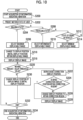
- Fig. 10 shows a flowchart showing an example of the flow of image processing that is performed by the processor 41 of the smartphone 12 of the present embodiment.
- Step S200 of Fig. 10 the acquisition unit 50 starts acquisition of information indicating vibration as described above. Specifically, the acquisition of the information indicating the vibration output from the vibration detection sensor 29 is started.
- the display region position change unit 53A predicts the motion state of the user.
- the method used by the display region position change unit 53A to predict the motion state of the user is not particularly limited.
- an aspect in which a machine learning model that has been trained a correspondence relationship between the information indicating the vibration and the motion state of the user is used and the motion state of the user according to the information indicating the vibration acquired by the acquisition unit 50 is predicted may be used.
- the information indicating the vibration or other information may be used to predict the motion state of the user.
- an aspect in which the moving speed of the user is detected, and based on the detection result, whether the motion state of the user is a stopped state, a walking state, a traveling state, or a state of riding in a vehicle is predicted may be used.
- Step S204 it is determined whether or not the prediction result is the walking state.
- the determination in Step S204 is an affirmative determination, and the processing proceeds to Step S206.
- Step S206 the display region position change unit 53A selects the maximum displayable range 71, specifically, the displayable range 71 shown in Fig. 9A , as the displayable range 71.
- Step S204 becomes a negative determination, and the processing proceeds to Step S208.
- Step S208 it is determined whether or not the prediction result is the traveling state. In a case in which it is the traveling state, the determination in Step S208 is an affirmative determination, and the processing proceeds to Step S210.
- Step S210 the display region position change unit 53A selects an intermediate displayable range 71, specifically, the displayable range 71 shown in Fig. 9B , as the displayable range 71.
- Step S208 becomes a negative determination, and the processing proceeds to Step S212.
- Step S212 it is determined whether or not the prediction result is the state of riding in the vehicle. In a state in which it is the state of riding in the vehicle, the determination in Step S212 is an affirmative determination, and the processing proceeds to Step S214.
- Step S214 the display region position change unit 53A selects the minimum displayable range 71, specifically, the displayable range 71 shown in Fig. 9C , as the displayable range 71.
- Step S212 becomes a negative determination, and the processing returns to Step S202.
- Step S216 the display region position change unit 53A changes the display position of the display image 80 to the displayable range 71. Specifically, the display position of the display image 80 is changed to within the displayable range 71 selected in any of Steps S206, S210, or S214, and the changed display position is set as the initial display position.
- the display controller 54 displays the display image 80 at the initial display position after the change in Step S216.
- the display region position change unit 53A determines whether or not the moving amount of the AR glasses 10 is equal to or greater than the blur threshold value based on the information indicating the vibration acquired by the acquisition unit 50. That is, it is determined whether or not the vibration is continuing. In a case in which the moving amount is equal to or greater than the blur threshold value, that is, in a case in which the vibration is continuing, the determination in Step S220 is an affirmative determination, and the processing proceeds to Step S222.
- Step S222 to S228 Since the processing of Steps S222 to S228 is the same as the processing of Steps S104 to S110 of the image processing (refer to Fig. 7 ) of the first embodiment, the description thereof will be omitted. In the present embodiment, after the end of Step S228, the processing returns to Step S220.
- Step S230 the image stabilization unit 52 changes the display position of the display image 80 being displayed to the initial display position.
- the initial display position here is the initial display position after the change in Step S216.
- Step S232 the acquisition unit 50 determines whether or not to end the image processing shown in Fig. 10 , that is, the image stabilization. As described above, while the display image 80 is being displayed, the determination in Step S232 is a negative determination, the processing returns to Step S220, and the processing of Steps S220 to S230 is repeated. On the other hand, in a case in which the display of the display image 80 ends, the determination in Step S232 is an affirmative determination, and the processing proceeds to Step S234.
- Step S234 the acquisition unit 50 ends the acquisition of the information indicating the vibration started in Step S200.
- the image processing shown in Fig. 10 ends.
- the initial display position is within the displayable range 71 according to the change of the relative position between the AR glasses 10 and the user's eye U
- the basic correction display position can be suppressed from exceeding the correction region 72. Therefore, a correction amount of the display position of the display image 80 can be reduced.
- the display position of the other display image 80 may be changed according to the display image 80 changed within the correction region 72.
- control may be performed such that the display images 80 are superimposed and displayed.
- a control of keeping the display position at the basic correction display position without changing the correction region 72 may be performed.
- the display image display position change unit 53B may selectively execute these three controls based on the user's instruction, the predetermined setting, or the like.
- a shape of the glasses-type information display device is not limited to a general shape of glasses, an application, or a wearing portion.
- the glasses-type information display device may be a monocular type or a compound eye type, and the aspect in which the projected image is visually recognized with one eye has been described in the above-mentioned embodiment, but the projected image may be visually recognized with both eyes.
- a shape in which the left and right sides are connected like goggles may be used.
- control device it is not limited to devices worn on a human head, like a so-called head-mounted display (for example, if a robot with the appearance of a dog simulates a function of a human, and the function of human eyes is achieved by a camera in the robot's knee, then the control device according to the embodiment of the present disclosure is mounted on the knee). Such a control device is also included in the technique of the present disclosure.
- the AR glasses 10 may comprise some or all of the functions of the processor 41 of the above-mentioned embodiment, or a device other than the glasses-type information display device 1 may comprise the functions.
- the following various processors can be used in the above-mentioned embodiment as the hardware structures of processing units, which perform various types of processing, such as the acquisition unit 50, the image stabilization unit 52 (the display region position change unit 53A and the display image display position change unit 53B), and the display controller 54.
- the various processors include a programmable logic device (PLD) that is a processor of which the circuit configuration can be changed after manufacture, such as a field programmable gate array (FPGA), a dedicated electrical circuit that is a processor having circuit configuration dedicatedly designed to perform specific processing, such as an application specific integrated circuit (ASIC), and the like in addition to a CPU that is a general-purpose processor functioning as various processing units by executing software (program) as described above.
- PLD programmable logic device
- FPGA field programmable gate array
- ASIC application specific integrated circuit
- One processing unit may be formed of one of these various processors, or may be formed of a combination of two or more processors of the same type or different types (for example, a combination of a plurality of FPGAs or a combination of a CPU and an FPGA).
- a plurality of processing units may be formed of one processor.
- a plurality of processing units are formed of one processor
- one processor is formed of a combination of one or more CPUs and software as typified by a computer, such as a client or a server, and functions as a plurality of processing units.
- a processor fulfilling the functions of the entire system which includes a plurality of processing units, by one integrated circuit (IC) chip as typified by System On Chip (SoC) or the like is used.
- IC integrated circuit
- SoC System On Chip
- circuit elements such as semiconductor elements
- circuit elements such as semiconductor elements
- the image processing program 45 may be provided in a form where the image processing program 45 is recorded in recording mediums, such as a compact disc read only memory (CD-ROM), a digital versatile disc read only memory (DVD-ROM), and a universal serial bus (USB) memory.
- the image processing program 45 may be downloaded from an external device through a network.
- a processor configured to, based on a change of a relative position between a transmissive display device and a user's eye, derive a second position according to a first position of a display image displayed in a display region of the display device and the change of the relative position, change the first position to the second position in a case in which the second position does not exceed a correction region where a correction of a display position is possible, and change the first position to a third position and display the display image within the correction region in a case in which the second position exceeds the correction region.
- the processor according to Supplementary Note 1 or 2 in which in a case in which a plurality of the display images are displayed in the display region, the processor independently corrects display positions of the plurality of display images.
- the processor according to any one of Supplementary Notes 1 to 3, in which in a case in which a first display image is superimposed on a second display image by changing a display position of the first display image to the third position, the processor performs a control to change a display position of the second display image according to the first display image after changing the display position to the third position.
- the processor in which in a case in which a first display image is superimposed on a second display image by changing a display position of the first display image to the third position, the processor selectively performs any of a first control to change a display position of the second display image according to the first display image after changing the display position to the third position, a second control to superimpose and display the first display image and the second display image, or a third control to set the display position of the first display image to the second position.
- the processor according to any one of Supplementary Notes 1 to 5, in which a displayable range in which the display of the display image is possible is predetermined according to a degree of the change of the relative position, and the processor changes the display position of the display image to within the displayable range.
- the processor selects the displayable range according to a motion state of the user, and changes the display position of the display image to within the selected displayable range.
- the processor according to any one of Supplementary Notes 1 to 7, in which in a case in which a change amount of the relative position exceeds a predetermined threshold value, the processor performs a control to hide the display image instead of changing the first position to the third position.
- the processor according to any one of Supplementary Notes 1 to 8, in which the display image is divided into a plurality of partial regions, and the third position is a position where at least a predetermined partial region among the plurality of partial regions is within the correction region.
- the processor in which a priority according to an area within the correction region is given to the display image, and in a case in which the second position exceeds the correction region, the processor changes the second position to the third position based on the priority.
- a case in which the second position exceeds the correction region where the correction of the display position is possible is a case in which at least a part of the display image is outside the correction region.
- a case in which the second position exceeds the correction region where the correction of the display position is possible is a case in which 90% or more of an area of the display image is outside the correction region.
- An image processing device comprising a processor configured to, based on a change of a relative position between a transmissive display device and a user's eye, derive a second position according to a first position of a display image displayed in a display region of the display device and the change of the relative position, change the first position to the second position in a case in which the second position does not exceed a correction region where a correction of a display position is possible, and change the first position to a third position and display the display image within the correction region in a case in which the second position exceeds the correction region.
- a glasses-type information display device comprising a transmissive display device, and the processor according to any one of Supplementary Notes 1 to 12.
- An image processing method executed by a processor comprising, based on a change of a relative position between a transmissive display device and a user's eye, deriving a second position according to a first position of a display image displayed in a display region of the display device and the change of the relative position, changing the first position to the second position in a case in which the second position does not exceed a correction region where a correction of a display position is possible, and changing the first position to a third position and displaying the display image within the correction region in a case in which the second position exceeds the correction region.
- An image processing program for causing a processor to execute a process comprising, based on a change of a relative position between a transmissive display device and a user's eye, deriving a second position according to a first position of a display image displayed in a display region of the display device and the change of the relative position, changing the first position to the second position in a case in which the second position does not exceed a correction region where a correction of a display position is possible, and changing the first position to a third position and displaying the display image within the correction region in a case in which the second position exceeds the correction region.
Landscapes
- Engineering & Computer Science (AREA)
- Physics & Mathematics (AREA)
- Theoretical Computer Science (AREA)
- General Physics & Mathematics (AREA)
- General Engineering & Computer Science (AREA)
- Computer Hardware Design (AREA)
- Human Computer Interaction (AREA)
- Optics & Photonics (AREA)
- Software Systems (AREA)
- Computer Graphics (AREA)
- Controls And Circuits For Display Device (AREA)
- Processing Or Creating Images (AREA)
- User Interface Of Digital Computer (AREA)
Abstract
Description
- The present disclosure relates to a processor, an image processing device, a glasses-type information display device, an image processing method, and a non-transitory storage medium storing an image processing program.
- A transmissive display device such as an augmented reality (AR) device that displays a state in which images are superimposed in a real space is known in the related art as a display device that displays a three-dimensional video.
- In a case in which a relative position between the transmissive display device and the user's eye changes, such as in a case in which the user is running, the display image displayed on the display device may be blurred and visually recognized. For this reason, in order to suppress blurred visual recognition, a technique for performing so-called image stabilization, in which a display position of a display image is changed so as to cancel a change of a relative position between the transmissive display device and the user's eye is known (for example, refer to
JP2014-110474A - However, in the technique of the related art, in a case in which the position of the display image is changed for image stabilization, the display image may not be displayed appropriately, for example, the display image may not be displayed.
- The present disclosure has been made in view of the above circumstances, and an object of the present disclosure is to provide a processor, an image processing device, a glasses-type information display device, an image processing method, and a non-transitory storage medium storing an image processing program capable of performing image stabilization for an appropriate display position of a display image.
- In order to achieve the above object, a processor of a first aspect of the present disclosure is configured to, based on a change of a relative position between a transmissive display device and a user's eye, derive a second position according to a first position of a display image displayed in a display region of the display device and the change of the relative position, change the first position to the second position in a case in which the second position does not exceed a correction region where a correction of a display position is possible, and change the first position to a third position and display the display image within the correction region in a case in which the second position exceeds the correction region.
- According to an embodiment, the processor is configured to change a position of the display region with respect to the correction region according to the change of the relative position.
- According to a processor of a third aspect of the present disclosure, in the processor of the second aspect, the processor is configured to independently correct display positions of the plurality of display images, in a case in which a plurality of the display images are displayed in the display region.
- According to an embodiment, the processor is configured to perform a control to change a display position of the second display image according to the first display image after changing the display position to the third position, in a case in which a first display image is superimposed on a second display image by changing a display position of the first display image to the third position.
- According to an embodiment, the processor is configured to selectively perform any of a first control to change a display position of the second display image according to the first display image after changing the display position to the third position, a second control to superimpose and display the first display image and the second display image, or a third control to set the display position of the first display image to the second position, in a case in which a first display image is superimposed on a second display image by changing a display position of the first display image to the third position.
- According to an embodiment, a displayable range in which the display of the display image is possible is predetermined according to a degree of the change of the relative position, and the processor is configured to change the display position of the display image to within the displayable range.
- According to an embodiment, the processor is configured to select the displayable range according to a motion state of the user, and changes the display position of the display image to within the selected displayable range.
- According to an embodiment, the processor is configured to perform a control to hide the display image instead of changing the first position to the third position, in a case in which a change amount of the relative position exceeds a predetermined threshold value.
- According to an embodiment, the display image is divided into a plurality of partial regions, and the third position is a position where at least a predetermined partial region among the plurality of partial regions is within the correction region.
- According to an embodiment, a priority according to an area within the correction region is given to the display image, and the processor is configured to change the second position to the third position based on the priority, in a case in which the second position exceeds the correction region.
- According to an embodiment, a case in which the second position exceeds the correction region where the correction of the display position is possible is a case in which at least a part of the display image is outside the correction region.
- According to an embodiment, a case in which the second position exceeds the correction region where the correction of the display position is possible is a case in which 90% or more of an area of the display image is outside the correction region.
- In order to achieve the above object, an image processing device of a further aspect of the present disclosure comprises a processor configured to, based on a change of a relative position between a transmissive display device and a user's eye, derive a second position according to a first position of a display image displayed in a display region of the display device and the change of the relative position, change the first position to the second position in a case in which the second position does not exceed a correction region where a correction of a display position is possible, and change the first position to a third position and display the display image within the correction region in a case in which the second position exceeds the correction region.
- In order to achieve the above object, a glasses-type information display device of a further aspect of the present disclosure comprises a transmissive display device and the processor of the present disclosure.
- In order to achieve the above object, an image processing method executed by a processor of a further aspect of the present disclosure comprises, based on a change of a relative position between a transmissive display device and a user's eye, deriving a second position according to a first position of a display image displayed in a display region of the display device and the change of the relative position, changing the first position to the second position in a case in which the second position does not exceed a correction region where a correction of a display position is possible, and changing the first position to a third position and displaying the display image within the correction region in a case in which the second position exceeds the correction region.
- In order to achieve the above object, a non- transitory storage medium storing an image processing program for causing a processor to execute a process of a further aspect of the present disclosure comprises, based on a change of a relative position between a transmissive display device and a user's eye, deriving a second position according to a first position of a display image displayed in a display region of the display device and the change of the relative position, changing the first position to the second position in a case in which the second position does not exceed a correction region where a correction of a display position is possible, and changing the first position to a third position and displaying the display image within the correction region in a case in which the second position exceeds the correction region.
- According to the present disclosure, it is possible to perform image stabilization for an appropriate display position of a display image.
-
-
Fig. 1 is a configuration diagram showing an example of a configuration of a glasses-type information display device according to an embodiment. -
Fig. 2 is a perspective view showing an example of AR glasses according to the embodiment. -
Fig. 3 is a block diagram showing an example of a hardware configuration of the smartphone according to the embodiment. -
Fig. 4 is a block diagram showing an example of a configuration of the processor according to the embodiment. -
Fig. 5A is a diagram for explaining image stabilization by the processor according to the embodiment. -
Fig. 5B is a diagram for explaining image stabilization by the processor according to the embodiment. -
Fig. 6A is a diagram for explaining an example in a case in which a display position by basic image stabilization exceeds a correction region. -
Fig. 6B is a diagram for explaining another example in a case in which the display position by the basic image stabilization exceeds the correction region. -
Fig. 7 is a flowchart showing an example of image processing executed by the processor according to the first embodiment. -
Fig. 8 is a diagram for explaining an example in which a display position of a display image is set within the correction region. -
Fig. 9A is a diagram for explaining an example of a displayable range in a walking state. -
Fig. 9B is a diagram for explaining an example of a displayable range in a traveling state. -
Fig. 9C is a diagram for explaining an example of a displayable range in a state of riding in a vehicle. -
Fig. 10 is a flowchart showing an example of image processing executed by the processor according to the second embodiment. - Hereinafter, examples of an embodiment for implementing the technique of the present disclosure will be described in detail with reference to the drawings.
- The configuration of a glasses-type information display device 1 according to the present embodiment will be described with reference to
Fig. 1 . As shown inFig. 1 , the glasses-type information display device 1 according to the present embodiment comprises augmented reality (AR)glasses 10 and asmartphone 12. - The
AR glasses 10 are a device that allows a user to visually recognize a projection image, which is projected from an organic light emitting diode (OLED) 26, in a state in which the projection image is superimposed on a real image.Fig. 2 is a perspective view of an example of theAR glasses 10 of the present embodiment. As shown inFigs. 1 and 2 , theAR glasses 10 comprise a pair of atransmission unit 20L for a left eye and atransmission unit 20R for a right eye, anOLED 26, andvibration detection sensor 29. TheAR glasses 10 of the present embodiment are an example of a transmissive display device of the present disclosure. - The OLED 26 projects an image (projection image), which represents information, onto the
transmission unit 20R for a right eye in order to insert information into the visual field of a real image, which is visually recognized by the user through thetransmission unit 20R for a right eye, in a superimposed manner. - The
transmission unit 20R for a right eye includes alens 22R for a right eye and alight guide plate 24. Light corresponding to the projection image projected from the OLED 26 is incident on one end of thelight guide plate 24. The direction of light propagated through thelight guide plate 24 is changed at an emission portion (not shown), and the light is emitted in a direction of the user's eye. The light, which is emitted from thelight guide plate 24 and corresponds to the projection image, is transmitted through thelens 22R for a right eye, is guided to the right eye of the user, and is visually recognized as a projected image with the right eye. In addition, the user visually recognizes a real space, which is shown through thelens 22R for a right eye, as a real image with the right eye. - For this reason, while the projection image is projected from the
OLED 26, the visually-recognized image visually recognized with the right eye of the user is in a state in which the projected image according to the projection image projected onto thelight guide plate 24 is superimposed on the real image representing the real space shown through thelens 22R for a right eye. In addition, while the projection image is not projected from theOLED 26, the visually-recognized image visually recognized by the user is the real image that represents the real space shown through thelens 22R for a right eye and thelight guide plate 24. - Meanwhile, the
transmission unit 20L for a left eye includes alens 22L for a left eye. The user visually recognizes the real space, which is shown through thelens 22L for a left eye, with the left eye. - The
vibration detection sensor 29 is a sensor that detects a change of a relative position between theAR glasses 10 and the user's eye as vibration of theAR glasses 10. That is, thevibration detection sensor 29 is a sensor that detects so-called "blur". Specifically, in thevibration detection sensor 29 is a sensor that detects a moving direction indicating whether theAR glasses 10 have moved in an in-plane direction of thelens 22R for a right eye, in other words, in a left-right or up-down direction of the user, and the moving amount in the moving direction. The moving direction and the moving amount detected by thevibration detection sensor 29 are output to thesmartphone 12 as information indicating vibration. - On the other hand, the
smartphone 12 comprises aprocessor 41. Theprocessor 41 of the present embodiment controls theOLED 26 to project the projection image onto thelight guide plate 24 from theOLED 26. In addition, theprocessor 41 of the present embodiment performs a control of correcting blurring, that is, a change of a relative position between theAR glasses 10 and the user's eye. Thesmartphone 12 of the present embodiment is an example of an image processing device of the present disclosure. -
Fig. 3 shows a block diagram showing an example of a hardware configuration of thesmartphone 12. As shown inFig. 3 , thesmartphone 12 comprises a central processing unit (CPU) 40, amemory 42, an interface (I/F)unit 43, astorage unit 44, adisplay 46, and aninput device 48. TheCPU 40, thememory 42, the I/F unit 43, thestorage unit 44, thedisplay 46, and theinput device 48 are connected to each other via abus 49, such as a system bus or a control bus, such that various types of information can be given and received therebetween. - The
CPU 40 reads out various programs, which include animage processing program 45 stored in thestorage unit 44, to thememory 42 and performs processing corresponding to the program read out. Accordingly, theCPU 40 performs a control of the image stabilization and a control of the display of the projected image by theOLED 26. As an example, theprocessor 41 of the present embodiment is composed of a combination of theCPU 40 and theimage processing program 45. Thememory 42 is a work memory that is used in a case in which theCPU 40 performs processing. - The
image processing program 45 executed in theCPU 40 is stored in thestorage unit 44. In addition, the image data (not shown) of the projection image projected from theOLED 26, various other types of information, and the like are also stored in thestorage unit 44. Specific examples of thestorage unit 44 include a hard disk drive (HDD), a solid state drive (SSD), and the like. - The I/
F unit 43 communicates various types of information to each of theOLED 26 using wireless communication or wired communication. Thedisplay 46 and theinput device 48 function as a user interface. Thedisplay 46 provides various types of information, which is related to the projection of the projection image, to a user. Thedisplay 46 is not particularly limited, and examples of thedisplay 46 include a liquid crystal monitor, a light emitting diode (LED) monitor, and the like. In addition, theinput device 48 is operated by a user so that various instructions related to the projection of the projection image are input. Theinput device 48 is not particularly limited, and examples of theinput device 48 include a keyboard, a touch pen, a mouse, and the like. A touch panel display in which thedisplay 46 and theinput device 48 are integrated with each other is employed in thesmartphone 12. -
Fig. 4 shows a functional block diagram showing an example of a configuration related to the function of theprocessor 41 of the present embodiment. As shown inFig. 4 , theprocessor 41 comprises anacquisition unit 50, animage stabilization unit 52, and a display controller 54. As an example, in thesmartphone 12 of the present embodiment, theCPU 40 executes theimage processing program 45 stored in thestorage unit 44, so that theCPU 40 functions as theacquisition unit 50, theimage stabilization unit 52, and the display controller 54. - The
acquisition unit 50 acquires information indicating the vibration from thevibration detection sensor 29 of theAR glasses 10. Theacquisition unit 50 outputs the acquired information indicating the vibration to theimage stabilization unit 52. - The
image stabilization unit 52 of the present embodiment has a function of correcting the display position of the display image to cancel the blur based on the information indicating the vibration. As shown inFig. 4 , theimage stabilization unit 52 includes a display regionposition change unit 53A and a display image displayposition change unit 53B. The image stabilization and a change of the display position of the display image by theimage stabilization unit 52 will be described with reference toFig. 5A and Fig. 5B . - As shown in
Fig. 5A , a state in which the user's eye U and theAR glasses 10 are facing each other is defined as an initial state in which no blurring occurs. In theAR glasses 10, adisplay region 70 that displays adisplay image 80 displayed by projecting a projection image from theOLED 26 is provided.Fig. 5A showsdisplay images 80Ato 80D as an example of thedisplay image 80. In the present embodiment, in a case in which thedisplay images 80A to 80D are collectively referred to without distinguishing between them, they are referred to as thedisplay image 80. - In addition, in the
AR glasses 10, acorrection region 72 for correcting the display position of thedisplay image 80 in a case in which blurring occurs is provided. A position of thecorrection region 72 is fixed with respect to thelens 22R for a right eye. As an example, in the present embodiment, the maximum region in which thedisplay image 80 can be displayed in theAR glasses 10 is defined as thecorrection region 72. As shown inFig. 5A , an area of thecorrection region 72 is greater than an area of thedisplay region 70. As an example, in theAR glasses 10 of the present embodiment, thedisplay region 70 is provided inside thecorrection region 72, and in the initial state, center positions of thedisplay region 70 and thecorrection region 72 are the same. -
Fig. 5B shows a case in which at least one of the downward movement of the user's eye U or the upward movement of theAR glasses 10 occurs as the change of the relative position from the state shown inFig. 5A . In this case, the display regionposition change unit 53A performs image stabilization that changes the position of thedisplay region 70 with respect to thelens 22R for a right eye in a downward direction so as to cancel the change of the relative position. As shown inFig. 5B , the relative position between the user's eye U and thedisplay region 70 does not change from the initial state by changing the position of thedisplay region 70 by the display regionposition change unit 53A. Since the display position of thedisplay image 80 is also changed in response to the change of the position of thedisplay region 70, the relative position between the user's eye U and the display position of thedisplay image 80 does not change from the initial state. Therefore, the user can visually recognize thedisplay image 80 as if it is not moving. - However, as shown in
Fig. 5B , in a case in which the amount of blurring is large, thedisplay region 70, whose position has been changed by the display regionposition change unit 53A, may exceed thecorrection region 72 to the outside. Thedisplay image 80 whose display position is within thedisplay region 70 outside thecorrection region 72 is not actually displayed on thelens 22R for a right eye and is not visually recognized by the user's eye U. In the example shown inFig. 5B , the display position of thedisplay image 80A indicated by a dotted line is outside thecorrection region 72. Therefore, thedisplay image 80A is not actually displayed on thelens 22R for a right eye and is not visually recognized by the user's eye U. - Therefore, the display image display
position change unit 53B of the present embodiment changes the display position of thedisplay image 80 whose display position is outside thecorrection region 72 to within thecorrection region 72. In the example shown inFig. 5B , the display position of thedisplay image 80A indicated by the dotted line is moved in a direction of an arrow Z, and the display position is changed to within thecorrection region 72 such that theentire display image 80A is within thecorrection region 72. In the example shown inFig. 5B , thedisplay image 80A after changing the display position to within thecorrection region 72 is indicated by a solid line. In this way, the user can visually recognize thedisplay image 80A by changing the display position of thedisplay image 80A to within thecorrection region 72. - In this way, the display region
position change unit 53A performs basic image stabilization that changes the position of thedisplay region 70 with respect to thelens 22R for a right eye based on the change of the relative position between the AR glasses 10 (lens 22R for a right eye) and the user's eye U. Specifically, the display regionposition change unit 53A of the present embodiment derives a display position (hereinafter, referred to as a basic correction display position) of thedisplay image 80 according to a display position (hereinafter, referred to as an initial display position) of thedisplay image 80 displayed in thedisplay region 70 in the initial state and the change of the relative position. In a case in which the display position of thedisplay image 80 derived by the display regionposition change unit 53A exceeds thecorrection region 72, the display image displayposition change unit 53B changes the display position of thedisplay image 80 to a position within thecorrection region 72. The initial display position of the present embodiment is an example of a first position of the present disclosure. In addition, the basic correction display position of thedisplay image 80 in a case in which the basic image stabilization is performed in the present embodiment is an example of a second position of the present disclosure. Further, the display position of thedisplay image 80 derived by the display image displayposition change unit 53B of the present embodiment is an example of a third position of the present disclosure. - The specific state in a case in which the display position of the
display image 80 exceeds thecorrection region 72 is not particularly limited and may be predetermined. For example, as shown inFig. 6A , in a case in which at least a part of thedisplay image 80 is outside thecorrection region 72, in other words, there may be a case in which thedisplay image 80 even slightly reaches outside thecorrection region 72. In addition, for example, as shown inFig. 6B , there may be a case in which 90% or more of the area of thedisplay image 80 is outside thecorrection region 72. - The
image stabilization unit 52 outputs the display positions of thedisplay images 80A to 80D derived by the display regionposition change unit 53A and the display image displayposition change unit 53B to the display controller 54. - The display controller 54 has a function of displaying the
display images 80A to 80D at the display position input from theimage stabilization unit 52. Specifically, the display controller 54 acquires image data of each of thedisplay images 80A to 80D projected by theOLED 26. As an example, in the present embodiment, since the image data of each of thedisplay images 80A to 80D is stored in thestorage unit 44, the display controller 54 acquires the image data of each of thedisplay images 80Ato 80D from thestorage unit 44. In addition, regardless of the present embodiment, an embodiment in which the image data of each of thedisplay images 80A to 80D may be acquired from an external device of thesmartphone 12 via the I/F unit 43 may be used. In the following, the image data of thedisplay images 80A to 80D will be simply referred to as display images, and for example, acquiring thedisplay image 80A is referred to as acquiring the display image. - Next, the action of the
processor 41 of the present embodiment will be described.Fig. 7 shows a flowchart showing an example of the flow of image processing that is performed by theprocessor 41 of thesmartphone 12 of the present embodiment. As an example, in theprocessor 41 of the present embodiment, in a case in which the projection of the projection image by theOLED 26 is started and the display of thedisplay image 80 is started, the image processing shown as an example inFig. 7 is executed. - In Step S100 of
Fig. 7 , theacquisition unit 50 starts acquisition of information indicating vibration as described above. Specifically, the acquisition of the information indicating the vibration output from thevibration detection sensor 29 is started. - In the next step S102, the display region position change unit 53Adetermines whether or not the moving amount of the
AR glasses 10 is equal to or greater than a blur threshold value based on the information indicating the vibration acquired by theacquisition unit 50. As an example, in the present embodiment, in a case in which the moving amount is extremely small, the image stabilization is not performed, that is, the position of thedisplay region 70 is not changed, and the position of thedisplay image 80 is also not changed. Therefore, in the present embodiment, in a case in which the moving amount is equal to or greater than the blur threshold value, it is assumed that the moving amount is large, and the image stabilization is performed. The method of determining the blur threshold value, which is a criterion for whether or not to perform the image stabilization, is not particularly limited, and for example, may use an experimentally obtained value or may be adjustable by an individual user. - In a case in which the moving amount is less than the blur threshold value, the determination in Step S102 is a negative determination. On the other hand, in a case in which the moving amount is equal to or greater than the blur threshold value, the determination in Step S102 is an affirmative determination, and the processing proceeds to Step S104.
- As described above, in Step S104, the display region
position change unit 53A derives a basic correction display position of thedisplay image 80 from the change of the relative position between theAR glasses 10 and the user's eye U and the initial display position in a case in which the basic image stabilization is performed. Specifically, the display regionposition change unit 53A derives the display position of thedisplay image 80 according to the moving direction and the moving amount of theAR glasses 10 included in the information indicating the vibration acquired in Step S100. For example, in a case in which the moving amount is 5 mm and the moving direction is the downward direction, the display position, which is moved in the upward direction by 5 mm from the initial display position, is derived as the display position of thedisplay image 80 as the basic correction display position. In a case in which a plurality ofdisplay images 80 are displayed in thedisplay region 70, the basic correction display position is corrected for each of the plurality ofdisplay images 80. - In the next step S106, the display image display
position change unit 53B determines whether or not the basic correction display position derived in Step S104 is within thecorrection region 72. In a case in which the basic correction display position is within thecorrection region 72, the determination in Step S106 is an affirmative determination, and the processing proceeds to Step S112. On the other hand, in a case in which the basic correction display position is outside thecorrection region 72, the determination in Step S106 is a negative determination, and the processing proceeds to Step S108. - In Step S108, the display image display
position change unit 53B changes the display position outside thecorrection region 72 to the display position within thecorrection region 72, as described above. The change amount and change direction of the display position for changing the display position outside thecorrection region 72 to the display position within thecorrection region 72 by the display image displayposition change unit 53B are not particularly limited. For example, as an aspect in which the display image displayposition change unit 53B changes the display position of thedisplay image 80 to within thecorrection region 72 may be used such that the change amount is minimized. - The display image display
position change unit 53B is not limited to a degree to which thedisplay image 80 is within thecorrection region 72 by changing the display position outside thecorrection region 72 to the display position within thecorrection region 72. For example, the display position may be changed such that theentire display image 80 is within thecorrection region 72, as in thedisplay image 80A ofFig. 5B described above. In addition, for example, as shown inFig. 8 , partial regions 811 to 814 are determined for thedisplay image 80, and the display position may be changed such that the predetermined partial region 81 (partial region 811 inFig. 8 ) is at least within thecorrection region 72. Which partial region 81 is to be at least within thecorrection region 72 may be determined by the content of thedisplay image 80, the display position of thedisplay image 80, or the like, and the method of determination is not particularly limited. - In addition, the display image display
position change unit 53B gives, for example, a priority to thedisplay image 80 according to the area within thecorrection region 72, and sets the display position of thedisplay image 80 to the display position within thecorrection region 72 based on the priority given to thedisplay image 80. For example, in a case in which the given priority is the highest, the display image displayposition change unit 53B may set the display position such that the entire area of thedisplay image 80 is within thecorrection region 72, as shown inFig. 5B described above, and may set the display position such that a part of the area of thedisplay image 80 is allowed to be outside thecorrection region 72 as the priority becomes lower. - In a case in which the plurality of
display images 80 are displayed in thedisplay region 70, the determinations in Step S106 and Step S108 are performed independently for eachdisplay image 80. That is, the display image displayposition change unit 53B corrects the display positions of the plurality ofdisplay images 80 independently. - In the next step S110, the display controller 54 perform a control to display the
display image 80. Specifically, for thedisplay image 80 in which the display position derived in Step S104 is within thecorrection region 72, thedisplay image 80 is displayed at the display position derived in Step S104. In addition, for thedisplay image 80 in which the display position has been changed to within thecorrection region 72 in Step S108, the display controller 54 displays thedisplay image 80 at the changed display position. - In the next step S112, the display region
position change unit 53A determines whether or not the moving amount of theAR glasses 10 is equal to or greater than the blur threshold value based on the information indicating the vibration acquired by theacquisition unit 50, as in Step S102. That is, it is determined whether or not the vibration is continuing. In a case in which the moving amount is equal to or greater than the blur threshold value, that is, in a case in which the vibration is continuing, the determination in Step S112 is an affirmative determination, and the processing proceeds to Step S116. - On the other hand, in a case in which the moving amount is less than the blur threshold value, that is, in a case in which the vibration is stopped, the determination in Step S112 is a negative determination, and the processing proceeds to Step S114. In Step S114, the
image stabilization unit 52 changes the display position of thedisplay image 80 being displayed to the initial display position. - In the next step S116, the
acquisition unit 50 determines whether or not to end the image processing shown inFig. 7 , that is, the image stabilization. As an example, in the present embodiment, while thedisplay image 80 is being displayed, the determination in Step S116 is a negative determination, the processing returns to Step S102, and the processing of Steps S102 to S114 is repeated. On the other hand, in a case in which the display of thedisplay image 80 ends, the determination in Step S116 is an affirmative determination, and the processing proceeds to Step S118. - In Step S118, the
acquisition unit 50 ends the acquisition of the information indicating the vibration started in Step S100. In a case in which the processing of Step S118 ends, the image processing shown inFig. 7 ends. - As described above, according to the
processor 41 of the present embodiment, the display position of thedisplay image 80 can be made appropriate in the image stabilization performed according to the change of the relative position between theAR glasses 10 and the user's eye U. - In the present embodiment, an aspect of changing the initial display position of the
display image 80 to a position within a predetermined displayable range according to the change of the relative position between theAR glasses 10 and the user's eye U will be described. The displayable range is a region in which the basic correction display position according to the change of the relative position between theAR glasses 10 and the user's eye U is predicted not to exceed thecorrection region 72 for thedisplay image 80 within the range. - For example, the change amount of the relative position between the
AR glasses 10 and the user's eye U varies depending on the motion state of the user. Therefore, in the present embodiment, an aspect in which a displayable range according to the motion of the user is selected and the initial display position of thedisplay image 80 is provided within the selected displayable range will be described. - For example, in a case in which the user is walking, the relative position between the
AR glasses 10 and the user's eye U is likely to change in the up-down direction of the user. Therefore, as shown inFig. 9A , in a case in which the user is walking, a range narrower in the up-down direction than thedisplay region 70 is provided within thedisplay region 70 as adisplayable range 71. - In addition, for example, in a case in which the user is traveling, the relative position between the
AR glasses 10 and the user's eye U is likely to change in the up-down direction of the user, and the change amount thereof is greater than in a case in which the user is walking. Therefore, as shown inFig. 9B , in a case in which the user is traveling, a range narrower even in the up-down direction than in a case in which the user is walking is provided within thedisplay region 70 as thedisplayable range 71. - In addition, for example, in a case in which the user is riding in a vehicle such as an automobile or a train, the relative position of the
AR glasses 10 and the user's eye U may change in the up-down and left-right directions of the user. Therefore, as shown inFig. 9C , in a case in which the user is riding in the vehicle, a range narrower in the up-down direction and the left-right direction than thedisplay region 70 is provided within thedisplay region 70 as thedisplayable range 71. - In a case in which the user is stopped, such as the user is standing still or sitting, the relative position between the
AR glasses 10 and the user's eye U does not change, and the display position of thedisplay image 80 remains the initial display position. Therefore, thedisplayable range 71 is not particularly provided. - Unlike the first embodiment, in the present embodiment, the display region
position change unit 53A of theimage stabilization unit 52 predicts the motion state of the user based on the information indicating the vibration acquired by theacquisition unit 50, and changes the initial display position of thedisplay image 80 to within thedisplayable range 71 according to the prediction result. -
Fig. 10 shows a flowchart showing an example of the flow of image processing that is performed by theprocessor 41 of thesmartphone 12 of the present embodiment. - In Step S200 of
Fig. 10 , theacquisition unit 50 starts acquisition of information indicating vibration as described above. Specifically, the acquisition of the information indicating the vibration output from thevibration detection sensor 29 is started. - In the next step S202, as described above, the display region
position change unit 53A predicts the motion state of the user. The method used by the display regionposition change unit 53A to predict the motion state of the user is not particularly limited. For example, an aspect in which a machine learning model that has been trained a correspondence relationship between the information indicating the vibration and the motion state of the user is used and the motion state of the user according to the information indicating the vibration acquired by theacquisition unit 50 is predicted may be used. In addition to the information indicating the vibration or other information may be used to predict the motion state of the user. For example, an aspect in which the moving speed of the user is detected, and based on the detection result, whether the motion state of the user is a stopped state, a walking state, a traveling state, or a state of riding in a vehicle is predicted may be used. - In the next step S204, it is determined whether or not the prediction result is the walking state. In the case of the walking state, the determination in Step S204 is an affirmative determination, and the processing proceeds to Step S206. In Step S206, the display region
position change unit 53A selects the maximumdisplayable range 71, specifically, thedisplayable range 71 shown inFig. 9A , as thedisplayable range 71. On the other hand, in a case in which it is not the walking state, Step S204 becomes a negative determination, and the processing proceeds to Step S208. - In Step S208, it is determined whether or not the prediction result is the traveling state. In a case in which it is the traveling state, the determination in Step S208 is an affirmative determination, and the processing proceeds to Step S210. In Step S210, the display region
position change unit 53A selects an intermediatedisplayable range 71, specifically, thedisplayable range 71 shown inFig. 9B , as thedisplayable range 71. On the other hand, in a case in which it is not the traveling state, Step S208 becomes a negative determination, and the processing proceeds to Step S212. - In Step S212, it is determined whether or not the prediction result is the state of riding in the vehicle. In a state in which it is the state of riding in the vehicle, the determination in Step S212 is an affirmative determination, and the processing proceeds to Step S214. In Step S214, the display region
position change unit 53A selects the minimumdisplayable range 71, specifically, thedisplayable range 71 shown inFig. 9C , as thedisplayable range 71. On the other hand, in a case in which it is not the state of riding in the vehicle, that is, it is the stop state, Step S212 becomes a negative determination, and the processing returns to Step S202. - In Step S216, the display region
position change unit 53A changes the display position of thedisplay image 80 to thedisplayable range 71. Specifically, the display position of thedisplay image 80 is changed to within thedisplayable range 71 selected in any of Steps S206, S210, or S214, and the changed display position is set as the initial display position. - In the next step S218, the display controller 54 displays the
display image 80 at the initial display position after the change in Step S216. - In the next step S220, in the same manner as in Step S112 of the image processing (refer to
Fig. 7 ) of the first embodiment, the display regionposition change unit 53A determines whether or not the moving amount of theAR glasses 10 is equal to or greater than the blur threshold value based on the information indicating the vibration acquired by theacquisition unit 50. That is, it is determined whether or not the vibration is continuing. In a case in which the moving amount is equal to or greater than the blur threshold value, that is, in a case in which the vibration is continuing, the determination in Step S220 is an affirmative determination, and the processing proceeds to Step S222. - Since the processing of Steps S222 to S228 is the same as the processing of Steps S104 to S110 of the image processing (refer to
Fig. 7 ) of the first embodiment, the description thereof will be omitted. In the present embodiment, after the end of Step S228, the processing returns to Step S220. - On the other hand, in a case in which the moving amount is less than the blur threshold value, that is, in a case in which the vibration is stopped, the determination in Step S220 is a negative determination, and the processing proceeds to Step S230. In Step S230, the
image stabilization unit 52 changes the display position of thedisplay image 80 being displayed to the initial display position. The initial display position here is the initial display position after the change in Step S216. - In the next step S232, the
acquisition unit 50 determines whether or not to end the image processing shown inFig. 10 , that is, the image stabilization. As described above, while thedisplay image 80 is being displayed, the determination in Step S232 is a negative determination, the processing returns to Step S220, and the processing of Steps S220 to S230 is repeated. On the other hand, in a case in which the display of thedisplay image 80 ends, the determination in Step S232 is an affirmative determination, and the processing proceeds to Step S234. - In Step S234, the
acquisition unit 50 ends the acquisition of the information indicating the vibration started in Step S200. In a case in which the processing of Step S234 ends, the image processing shown inFig. 10 ends. - In this way, according to the
processor 41 of the present embodiment, since the initial display position is within thedisplayable range 71 according to the change of the relative position between theAR glasses 10 and the user's eye U, the basic correction display position can be suppressed from exceeding thecorrection region 72. Therefore, a correction amount of the display position of thedisplay image 80 can be reduced. - In each of the above-mentioned embodiments, in a case in which the
display image 80 is superimposed on anotherdisplay image 80 by changing the display position of thedisplay image 80 to within thecorrection region 72 using the display image displayposition change unit 53B, the display position of theother display image 80 may be changed according to thedisplay image 80 changed within thecorrection region 72. - In addition to the control of changing the display position of the
other display image 80 as described above, the control may be performed such that thedisplay images 80 are superimposed and displayed. In addition, a control of keeping the display position at the basic correction display position without changing thecorrection region 72 may be performed. In addition, an aspect in which the display image displayposition change unit 53B may selectively execute these three controls based on the user's instruction, the predetermined setting, or the like. - A shape of the glasses-type information display device is not limited to a general shape of glasses, an application, or a wearing portion. In addition, the glasses-type information display device may be a monocular type or a compound eye type, and the aspect in which the projected image is visually recognized with one eye has been described in the above-mentioned embodiment, but the projected image may be visually recognized with both eyes. A shape in which the left and right sides are connected like goggles may be used. In addition, it is not limited to devices worn on a human head, like a so-called head-mounted display (for example, if a robot with the appearance of a dog simulates a function of a human, and the function of human eyes is achieved by a camera in the robot's knee, then the control device according to the embodiment of the present disclosure is mounted on the knee). Such a control device is also included in the technique of the present disclosure.
- In addition, the
AR glasses 10 may comprise some or all of the functions of theprocessor 41 of the above-mentioned embodiment, or a device other than the glasses-type information display device 1 may comprise the functions. - In addition, the following various processors can be used in the above-mentioned embodiment as the hardware structures of processing units, which perform various types of processing, such as the
acquisition unit 50, the image stabilization unit 52 (the display regionposition change unit 53A and the display image displayposition change unit 53B), and the display controller 54. The various processors include a programmable logic device (PLD) that is a processor of which the circuit configuration can be changed after manufacture, such as a field programmable gate array (FPGA), a dedicated electrical circuit that is a processor having circuit configuration dedicatedly designed to perform specific processing, such as an application specific integrated circuit (ASIC), and the like in addition to a CPU that is a general-purpose processor functioning as various processing units by executing software (program) as described above. - One processing unit may be formed of one of these various processors, or may be formed of a combination of two or more processors of the same type or different types (for example, a combination of a plurality of FPGAs or a combination of a CPU and an FPGA). In addition, a plurality of processing units may be formed of one processor.
- As an example in which a plurality of processing units are formed of one processor, first, as in the above-mentioned embodiment, there is an aspect in which one processor is formed of a combination of one or more CPUs and software as typified by a computer, such as a client or a server, and functions as a plurality of processing units. Second, there is an aspect where a processor fulfilling the functions of the entire system, which includes a plurality of processing units, by one integrated circuit (IC) chip as typified by System On Chip (SoC) or the like is used. In this way, various processing units are formed using one or more of the above-mentioned various processors as hardware structures.
- Furthermore, more specifically, electrical circuitry in which circuit elements, such as semiconductor elements, are combined can be used as the hardware structures of these various processors.
- In addition, an aspect in which the
image processing program 45 is stored (installed) in thestorage unit 44 in advance has been described in each above-mentioned embodiment, but the present disclosure is not limited thereto. Theimage processing program 45 may be provided in a form where theimage processing program 45 is recorded in recording mediums, such as a compact disc read only memory (CD-ROM), a digital versatile disc read only memory (DVD-ROM), and a universal serial bus (USB) memory. In addition, theimage processing program 45 may be downloaded from an external device through a network. - In regard to the embodiment described above, the following supplementary notes will be further disclosed.
- A processor configured to, based on a change of a relative position between a transmissive display device and a user's eye, derive a second position according to a first position of a display image displayed in a display region of the display device and the change of the relative position, change the first position to the second position in a case in which the second position does not exceed a correction region where a correction of a display position is possible, and change the first position to a third position and display the display image within the correction region in a case in which the second position exceeds the correction region.
- The processor according to Supplementary Note 1, in which a position of the display region with respect to the correction region is changed according to the change of the relative position.
- The processor according to Supplementary Note 1 or 2, in which in a case in which a plurality of the display images are displayed in the display region, the processor independently corrects display positions of the plurality of display images.
- The processor according to any one of Supplementary Notes 1 to 3, in which in a case in which a first display image is superimposed on a second display image by changing a display position of the first display image to the third position, the processor performs a control to change a display position of the second display image according to the first display image after changing the display position to the third position.
- The processor according to any one of Supplementary Notes 1 to 3, in which in a case in which a first display image is superimposed on a second display image by changing a display position of the first display image to the third position, the processor selectively performs any of a first control to change a display position of the second display image according to the first display image after changing the display position to the third position, a second control to superimpose and display the first display image and the second display image, or a third control to set the display position of the first display image to the second position.
- The processor according to any one of Supplementary Notes 1 to 5, in which a displayable range in which the display of the display image is possible is predetermined according to a degree of the change of the relative position, and the processor changes the display position of the display image to within the displayable range.
- The processor according to Supplementary Note 6, in which the processor selects the displayable range according to a motion state of the user, and changes the display position of the display image to within the selected displayable range.
- The processor according to any one of Supplementary Notes 1 to 7, in which in a case in which a change amount of the relative position exceeds a predetermined threshold value, the processor performs a control to hide the display image instead of changing the first position to the third position.
- The processor according to any one of Supplementary Notes 1 to 8, in which the display image is divided into a plurality of partial regions, and the third position is a position where at least a predetermined partial region among the plurality of partial regions is within the correction region.
- The processor according to any one of Supplementary Notes 1 to 8, in which a priority according to an area within the correction region is given to the display image, and in a case in which the second position exceeds the correction region, the processor changes the second position to the third position based on the priority.
- The processor according to any one of Supplementary Notes 1 to 10, in which a case in which the second position exceeds the correction region where the correction of the display position is possible is a case in which at least a part of the display image is outside the correction region.
- The processor according to any one of Supplementary Notes 1 to 10, in which a case in which the second position exceeds the correction region where the correction of the display position is possible is a case in which 90% or more of an area of the display image is outside the correction region.
- An image processing device comprising a processor configured to, based on a change of a relative position between a transmissive display device and a user's eye, derive a second position according to a first position of a display image displayed in a display region of the display device and the change of the relative position, change the first position to the second position in a case in which the second position does not exceed a correction region where a correction of a display position is possible, and change the first position to a third position and display the display image within the correction region in a case in which the second position exceeds the correction region.
- A glasses-type information display device comprising a transmissive display device, and the processor according to any one of Supplementary Notes 1 to 12.
- An image processing method executed by a processor, comprising, based on a change of a relative position between a transmissive display device and a user's eye, deriving a second position according to a first position of a display image displayed in a display region of the display device and the change of the relative position, changing the first position to the second position in a case in which the second position does not exceed a correction region where a correction of a display position is possible, and changing the first position to a third position and displaying the display image within the correction region in a case in which the second position exceeds the correction region.
- An image processing program for causing a processor to execute a process comprising, based on a change of a relative position between a transmissive display device and a user's eye, deriving a second position according to a first position of a display image displayed in a display region of the display device and the change of the relative position, changing the first position to the second position in a case in which the second position does not exceed a correction region where a correction of a display position is possible, and changing the first position to a third position and displaying the display image within the correction region in a case in which the second position exceeds the correction region.
Claims (16)
- A processor configured to:based on a change of a relative position between a transmissive display device (10) and a user's eye,derive a second position according to a first position of a display image displayed in a display region of the display device and the change of the relative position;change the first position to the second position in a case in which the second position does not exceed a correction region where a correction of a display position is possible; andchange the first position to a third position and display the display image within the correction region in a case in which the second position exceeds the correction region.
- The processor according to claim 1,
wherein the processor (41) is configured to change a position of the display region with respect to the correction region according to the change of the relative position. - The processor according to claim 1 or 2,
wherein the processor (41) is configured to independently correct display positions of the plurality of display images, in a case in which a plurality of the display images are displayed in the display region. - The processor according to any one of claims 1 to 3,
wherein the processor (41) is configured to perform a control to change a display position of the second display image according to the first display image after changing the display position to the third position, in a case in which a first display image is superimposed on a second display image by changing a display position of the first display image to the third position. - The processor according to any one of claims 1 to 3,
wherein the processor (41) is configured to selectively perform any of a first control to change a display position of the second display image according to the first display image after changing the display position to the third position, a second control to superimpose and display the first display image and the second display image, or a third control to set the display position of the first display image to the second position, in a case in which a first display image is superimposed on a second display image by changing a display position of the first display image to the third position. - The processor according to any one of claims 1 to 5,wherein a displayable range in which the display of the display image is possible is predetermined according to a degree of the change of the relative position, andthe processor is configured to change the display position of the display image to within the displayable range.
- The processor according to claim 6,
wherein the processor (41) is configured to:select the displayable range according to a motion state of the user, andchange the display position of the display image to within the selected displayable range. - The processor according to any one of claims 1 to 7,
wherein the processor (41) is configured to perform a control to hide the display image instead of changing the first position to the third position, in a case in which a change amount of the relative position exceeds a predetermined threshold value. - The processor according to any one of claims 1 to 8,wherein the display image is divided into a plurality of partial regions, andthe third position is a position where at least a predetermined partial region among the plurality of partial regions is within the correction region.
- The processor according to any one of claims 1 to 8,wherein a priority according to an area within the correction region is given to the display image, andthe processor is configured to change the second position to the third position based on the priority, in a case in which the second position exceeds the correction region.
- The processor according to any one of claims 1 to 10,
wherein a case in which the second position exceeds the correction region where the correction of the display position is possible is a case in which at least a part of the display image is outside the correction region. - The processor according to any one of claims 1 to 10,
wherein a case in which the second position exceeds the correction region where the correction of the display position is possible is a case in which 90% or more of an area of the display image is outside the correction region. - An image processing device comprising:a processor (41) configured to, based on a change of a relative position between a transmissive display device (10) and a user's eye,derive a second position according to a first position of a display image displayed in a display region of the display device and the change of the relative position,change the first position to the second position in a case in which the second position does not exceed a correction region where a correction of a display position is possible, andchange the first position to a third position and display the display image within the correction region in a case in which the second position exceeds the correction region.
- A glasses-type information display device comprising:a transmissive display device (10); andthe processor (41) according to any one of claims 1 to 12.
- An image processing method executed by a processor, comprising:based on a change of a relative position between a transmissive display device and a user's eye,deriving a second position according to a first position of a display image displayed in a display region of the display device and the change of the relative position;changing the first position to the second position in a case in which the second position does not exceed a correction region where a correction of a display position is possible; andchanging the first position to a third position and displaying the display image within the correction region in a case in which the second position exceeds the correction region.
- A non-transitory storage medium storing an image processing program for causing a processor to execute a process comprising:based on a change of a relative position between a transmissive display device and a user's eye,deriving a second position according to a first position of a display image displayed in a display region of the display device and the change of the relative position;changing the first position to the second position in a case in which the second position does not exceed a correction region where a correction of a display position is possible; andchanging the first position to a third position and displaying the display image within the correction region in a case in which the second position exceeds the correction region.
Applications Claiming Priority (1)
| Application Number | Priority Date | Filing Date | Title |
|---|---|---|---|
| JP2022144849A JP2024040035A (en) | 2022-09-12 | 2022-09-12 | Processor, image processing device, glasses-type information display device, image processing method, and image processing program |
Publications (2)
| Publication Number | Publication Date |
|---|---|
| EP4336342A2 true EP4336342A2 (en) | 2024-03-13 |
| EP4336342A3 EP4336342A3 (en) | 2024-05-08 |
Family
ID=88017892
Family Applications (1)
| Application Number | Title | Priority Date | Filing Date |
|---|---|---|---|
| EP23196665.6A Pending EP4336342A3 (en) | 2022-09-12 | 2023-09-11 | Processor, image processing device, glasses-type information display device, image processing method, and image processing program |
Country Status (4)
| Country | Link |
|---|---|
| US (2) | US12346621B2 (en) |
| EP (1) | EP4336342A3 (en) |
| JP (1) | JP2024040035A (en) |
| CN (1) | CN117687503A (en) |
Citations (1)
| Publication number | Priority date | Publication date | Assignee | Title |
|---|---|---|---|---|
| JP2014110474A (en) | 2012-11-30 | 2014-06-12 | Olympus Corp | Head-mounted device |
Family Cites Families (13)
| Publication number | Priority date | Publication date | Assignee | Title |
|---|---|---|---|---|
| US8681093B2 (en) | 2008-02-11 | 2014-03-25 | Apple Inc. | Motion compensation for screens |
| US9417666B2 (en) * | 2012-10-19 | 2016-08-16 | Microsoft Technology Licesning, LLC | User and device movement based display compensation |
| US10951310B2 (en) * | 2012-12-27 | 2021-03-16 | Panasonic Intellectual Property Corporation Of America | Communication method, communication device, and transmitter |
| KR20150071344A (en) | 2013-12-18 | 2015-06-26 | 삼성전기주식회사 | Apparatus and method for stabilizing image of display |
| US10444847B2 (en) | 2014-12-31 | 2019-10-15 | Oath Inc. | Stabilizing content display on wearable devices |
| US9706086B2 (en) | 2015-08-26 | 2017-07-11 | Intel Corporation | Camera-assisted display motion compensation |
| JP2017068595A (en) | 2015-09-30 | 2017-04-06 | ソニー株式会社 | Information processing device, information processing method, and program |
| CN106921890A (en) | 2015-12-24 | 2017-07-04 | 上海贝尔股份有限公司 | A kind of method and apparatus of the Video Rendering in the equipment for promotion |
| JP2018004756A (en) * | 2016-06-28 | 2018-01-11 | 株式会社リコー | Information display system |
| JP7013128B2 (en) * | 2017-01-27 | 2022-01-31 | キヤノン株式会社 | Image display device, image display method and program |
| US10726814B2 (en) | 2017-01-27 | 2020-07-28 | Canon Kabushiki Kaisha | Image display apparatus, image processing apparatus, image display method, image processing method, and storage medium |
| JP7287950B2 (en) * | 2018-03-30 | 2023-06-06 | パナソニック インテレクチュアル プロパティ コーポレーション オブ アメリカ | COMMUNICATION METHOD, COMMUNICATION DEVICE, AND PROGRAM |
| JP2021124529A (en) * | 2020-01-31 | 2021-08-30 | キヤノン株式会社 | Image processing apparatus, image processing system, image processing method, and program |
-
2022
- 2022-09-12 JP JP2022144849A patent/JP2024040035A/en active Pending
-
2023
- 2023-09-08 CN CN202311161531.4A patent/CN117687503A/en active Pending
- 2023-09-08 US US18/463,635 patent/US12346621B2/en active Active
- 2023-09-11 EP EP23196665.6A patent/EP4336342A3/en active Pending
-
2025
- 2025-06-04 US US19/228,104 patent/US20250298567A1/en active Pending
Patent Citations (1)
| Publication number | Priority date | Publication date | Assignee | Title |
|---|---|---|---|---|
| JP2014110474A (en) | 2012-11-30 | 2014-06-12 | Olympus Corp | Head-mounted device |
Also Published As
| Publication number | Publication date |
|---|---|
| US20240086133A1 (en) | 2024-03-14 |
| US12346621B2 (en) | 2025-07-01 |
| JP2024040035A (en) | 2024-03-25 |
| EP4336342A3 (en) | 2024-05-08 |
| CN117687503A (en) | 2024-03-12 |
| US20250298567A1 (en) | 2025-09-25 |
Similar Documents
| Publication | Publication Date | Title |
|---|---|---|
| US9521325B2 (en) | Terminal device and line of sight detection method | |
| JP7198023B2 (en) | Eyeball information estimation device, eyeball information estimation method, and eyeball information estimation program | |
| US20170232343A1 (en) | Method and system for adjusting a field of view region in a virtual space | |
| US10304253B2 (en) | Computer program, object tracking method, and display device | |
| US11301969B1 (en) | Context aware dynamic distortion correction | |
| US11308685B2 (en) | Rendering computer-generated reality text | |
| EP4425305A1 (en) | Processor, image processing method, and image processing program | |
| US12175711B2 (en) | Determining optical center in an image | |
| EP4336342A2 (en) | Processor, image processing device, glasses-type information display device, image processing method, and image processing program | |
| JP2018180623A (en) | Sight line direction estimation device and sight line direction estimation method | |
| EP4312205A1 (en) | Control device, glasses-type information display device, control method, and control program | |
| US20240087299A1 (en) | Image processing apparatus, image processing method, and image processing computer program product | |
| US11972549B2 (en) | Frame selection for image matching in rapid target acquisition | |
| EP4336319B1 (en) | Processor, image processing device, glasses-type information display device, image processing method, and image processing program | |
| US12189849B2 (en) | Processor, information processing method, and information processing program | |
| JP2012023567A (en) | Display device, image processing device, and program | |
| US12323747B2 (en) | Control device, control method, and control program for augmented reality device which adjusts a projection image brightness according to a measured user pupil size | |
| JP7652053B2 (en) | AR Glasses Overlay Display Control Device | |
| EP4312191A1 (en) | Image processing device, glasses-type information display device, image processing method, and image processing program | |
| WO2025196865A1 (en) | Information processing device, information processing method, and recording medium | |
| JP2020190601A (en) | Display controller, display system, method and computer program |
Legal Events
| Date | Code | Title | Description |
|---|---|---|---|
| PUAI | Public reference made under article 153(3) epc to a published international application that has entered the european phase |
Free format text: ORIGINAL CODE: 0009012 |
|
| STAA | Information on the status of an ep patent application or granted ep patent |
Free format text: STATUS: THE APPLICATION HAS BEEN PUBLISHED |
|
| AK | Designated contracting states |
Kind code of ref document: A2 Designated state(s): AL AT BE BG CH CY CZ DE DK EE ES FI FR GB GR HR HU IE IS IT LI LT LU LV MC ME MK MT NL NO PL PT RO RS SE SI SK SM TR |
|
| PUAL | Search report despatched |
Free format text: ORIGINAL CODE: 0009013 |
|
| AK | Designated contracting states |
Kind code of ref document: A3 Designated state(s): AL AT BE BG CH CY CZ DE DK EE ES FI FR GB GR HR HU IE IS IT LI LT LU LV MC ME MK MT NL NO PL PT RO RS SE SI SK SM TR |
|
| RIC1 | Information provided on ipc code assigned before grant |
Ipc: G06F 3/01 20060101ALI20240404BHEP Ipc: G06F 3/048 20130101ALI20240404BHEP Ipc: G02B 27/01 20060101ALI20240404BHEP Ipc: G02B 27/00 20060101ALI20240404BHEP Ipc: G09G 5/38 20060101ALI20240404BHEP Ipc: G06F 3/147 20060101AFI20240404BHEP |
|
| STAA | Information on the status of an ep patent application or granted ep patent |
Free format text: STATUS: REQUEST FOR EXAMINATION WAS MADE |
|
| 17P | Request for examination filed |
Effective date: 20241105 |
|
| RBV | Designated contracting states (corrected) |
Designated state(s): AL AT BE BG CH CY CZ DE DK EE ES FI FR GB GR HR HU IE IS IT LI LT LU LV MC ME MK MT NL NO PL PT RO RS SE SI SK SM TR |
|
| STAA | Information on the status of an ep patent application or granted ep patent |
Free format text: STATUS: EXAMINATION IS IN PROGRESS |
|
| 17Q | First examination report despatched |
Effective date: 20250818 |