EP4336117A1 - Air duct member, ventilation and heat exchange component, and air conditioner - Google Patents
Air duct member, ventilation and heat exchange component, and air conditioner Download PDFInfo
- Publication number
- EP4336117A1 EP4336117A1 EP22819418.9A EP22819418A EP4336117A1 EP 4336117 A1 EP4336117 A1 EP 4336117A1 EP 22819418 A EP22819418 A EP 22819418A EP 4336117 A1 EP4336117 A1 EP 4336117A1
- Authority
- EP
- European Patent Office
- Prior art keywords
- air duct
- water receiving
- air
- drainage hole
- receiving recess
- Prior art date
- Legal status (The legal status is an assumption and is not a legal conclusion. Google has not performed a legal analysis and makes no representation as to the accuracy of the status listed.)
- Pending
Links
Images




Classifications
-
- F—MECHANICAL ENGINEERING; LIGHTING; HEATING; WEAPONS; BLASTING
- F24—HEATING; RANGES; VENTILATING
- F24F—AIR-CONDITIONING; AIR-HUMIDIFICATION; VENTILATION; USE OF AIR CURRENTS FOR SCREENING
- F24F1/00—Room units for air-conditioning, e.g. separate or self-contained units or units receiving primary air from a central station
- F24F1/0007—Indoor units, e.g. fan coil units
- F24F1/0011—Indoor units, e.g. fan coil units characterised by air outlets
- F24F1/0014—Indoor units, e.g. fan coil units characterised by air outlets having two or more outlet openings
-
- F—MECHANICAL ENGINEERING; LIGHTING; HEATING; WEAPONS; BLASTING
- F24—HEATING; RANGES; VENTILATING
- F24F—AIR-CONDITIONING; AIR-HUMIDIFICATION; VENTILATION; USE OF AIR CURRENTS FOR SCREENING
- F24F13/00—Details common to, or for air-conditioning, air-humidification, ventilation or use of air currents for screening
- F24F13/22—Means for preventing condensation or evacuating condensate
-
- F—MECHANICAL ENGINEERING; LIGHTING; HEATING; WEAPONS; BLASTING
- F24—HEATING; RANGES; VENTILATING
- F24F—AIR-CONDITIONING; AIR-HUMIDIFICATION; VENTILATION; USE OF AIR CURRENTS FOR SCREENING
- F24F1/00—Room units for air-conditioning, e.g. separate or self-contained units or units receiving primary air from a central station
- F24F1/0007—Indoor units, e.g. fan coil units
- F24F1/0059—Indoor units, e.g. fan coil units characterised by heat exchangers
- F24F1/0063—Indoor units, e.g. fan coil units characterised by heat exchangers by the mounting or arrangement of the heat exchangers
-
- F—MECHANICAL ENGINEERING; LIGHTING; HEATING; WEAPONS; BLASTING
- F24—HEATING; RANGES; VENTILATING
- F24F—AIR-CONDITIONING; AIR-HUMIDIFICATION; VENTILATION; USE OF AIR CURRENTS FOR SCREENING
- F24F13/00—Details common to, or for air-conditioning, air-humidification, ventilation or use of air currents for screening
- F24F13/02—Ducting arrangements
-
- F—MECHANICAL ENGINEERING; LIGHTING; HEATING; WEAPONS; BLASTING
- F24—HEATING; RANGES; VENTILATING
- F24F—AIR-CONDITIONING; AIR-HUMIDIFICATION; VENTILATION; USE OF AIR CURRENTS FOR SCREENING
- F24F13/00—Details common to, or for air-conditioning, air-humidification, ventilation or use of air currents for screening
- F24F13/22—Means for preventing condensation or evacuating condensate
- F24F13/222—Means for preventing condensation or evacuating condensate for evacuating condensate
-
- F—MECHANICAL ENGINEERING; LIGHTING; HEATING; WEAPONS; BLASTING
- F24—HEATING; RANGES; VENTILATING
- F24F—AIR-CONDITIONING; AIR-HUMIDIFICATION; VENTILATION; USE OF AIR CURRENTS FOR SCREENING
- F24F1/00—Room units for air-conditioning, e.g. separate or self-contained units or units receiving primary air from a central station
- F24F1/0007—Indoor units, e.g. fan coil units
- F24F1/0043—Indoor units, e.g. fan coil units characterised by mounting arrangements
- F24F1/005—Indoor units, e.g. fan coil units characterised by mounting arrangements mounted on the floor; standing on the floor
-
- F—MECHANICAL ENGINEERING; LIGHTING; HEATING; WEAPONS; BLASTING
- F24—HEATING; RANGES; VENTILATING
- F24F—AIR-CONDITIONING; AIR-HUMIDIFICATION; VENTILATION; USE OF AIR CURRENTS FOR SCREENING
- F24F1/00—Room units for air-conditioning, e.g. separate or self-contained units or units receiving primary air from a central station
- F24F1/02—Self-contained room units for air-conditioning, i.e. with all apparatus for treatment installed in a common casing
Definitions
- the present disclosure relates to the field of air conditioners, and more particularly, to an air duct member, a ventilation and heat exchange component, and an air conditioner.
- a conventional air conditioner is provided with an air duct structure.
- condensed water is likely to be generated on an outer surface of a second air duct wall of the air duct structure, and flows downwardly into the air conditioner by gravity. If the condensed water cannot flow into a water receiving pan of the air conditioner, it is prone to cause a short circuit in the air conditioner.
- an insulation layer is disposed at the outer surface of the second air duct wall.
- the insulation layer may be a sponge, which can absorb the condensed water on the outer surface of the second air duct wall.
- the sponge is susceptible to mould and bacterial growth after repeated dry-wet cycles over a long period of time, generating an unpleasant odour.
- arranging the sponge would increase assembly steps and wastes manpower. Also, more materials are used, resulting in a waste of resources.
- the present disclosure aims to solve at least one of the technical problems in the related art.
- embodiments of the present disclosure provide an air duct member, which can avoid an unpleasant odour generated by the air duct member, simplify assembly steps of the air duct member, and save materials and resources.
- Embodiments of the present disclosure further provide a ventilation and heat exchange component.
- Embodiments of the present disclosure further provide an air conditioner.
- an air duct member includes an air duct portion and a water receiving portion.
- the air duct potion includes at least one air duct structure, and the at least one air duct structure has a first air duct wall and a second air duct wall spaced apart from each other.
- a cross-flow air duct is defined between the first air duct wall and the second air duct wall.
- the first air duct wall includes a volute tongue structure.
- the water receiving portion is disposed at a lower end of the air duct portion and defines a water receiving recess located outside the cross-flow air duct.
- the water receiving recess is located at a side of the second air duct wall away from the first air duct wall and adapted to receive condensed water flowing down along an outer surface of the second air duct wall.
- the air duct member of the present disclosure by arranging the water receiving portion at the lower end of the air duct portion, the condensed water flowing down along the outer surface of the second air duct wall can flow into the water receiving recess.
- a sponge at the outer surface of the second air duct wall which can avoid a situation that the sponge is susceptible to mould and bacterial growth after repeated dry-wet cycles over a long period of time. Therefore, it is possible to prevent the air duct member from generating an unpleasant odour.
- the step of arranging the sponge at the outer surface of the second air duct wall is removed, which can simplify the assembly steps of the air duct member and save manpower. Also, materials and resources can be saved.
- the air duct portion includes a left air duct structure and a right air duct structure arranged in a left-right direction.
- the left air duct structure has an air duct outlet extending in a left front direction.
- the right air duct structure has an air outlet extending in a right front direction.
- the second air duct wall of the left air duct structure and the second air duct wall of the right air duct structure are located close to each other, and the first air duct wall of the left air duct structure and the first air duct wall of the right air duct structure are located away from each other.
- the water receiving recess is located between lower ends of the two second air duct walls.
- the water receiving recess has a first drainage hole located at a central position in the left-right direction, and a bottom surface of the water receiving recess extends obliquely downwards from front to rear.
- a front end of the water receiving recess has an avoidance notch recessed rearwards.
- the air duct member further includes a support portion.
- the support portion is located between the two second air duct walls and configured to support the two second air duct walls.
- the support portion is spaced apart from the water receiving recess and located above the water receiving recess, and an edge of the support portion has a second drainage hole.
- the two second air duct walls are spaced apart from each other to form a gap between the two second air duct walls; and the air duct member further includes a connection portion disposed in the gap between the two second air duct walls and connecting the two second air duct walls.
- the connection portion is located at a rear side of the support portion.
- the second drainage hole is defined between a rear end of the support portion and the connection portion.
- a drainage channel is defined between the connection portion and the gap between the two second air duct walls and extends vertically.
- the second drainage hole is configured to discharge water towards the water receiving recess through the drainage channel.
- the support portion is provided with a hook located at a front end of the support portion.
- the hook includes a support segment extending transversely and a hooking segment extending upwards from the support segment.
- a water collection recess is defined in the support portion.
- the support portion includes a flow guide rib disposed in the water collection recess.
- the flow guide rib is configured to guide water in the water collection recess to flow towards the second drainage hole.
- the second air duct wall is provided with a cable holder.
- the water receiving portion and at least part of the second air duct wall are integrally formed.
- the water receiving recess has a first drainage hole, and a bottom surface of the water receiving recess extends obliquely downwards towards the first drainage hole.
- the air duct member further includes a flow guide portion located below the water receiving recess and defining a flow guide channel.
- the flow guide channel has an upper end in communication with the first drainage hole and a lower end having a third drainage hole.
- the third drainage hole is located below the first drainage hole and offset from the first drainage hole in a horizontal direction.
- a ventilation and heat exchange component includes a ventilation assembly, a heat exchange assembly, and a water receiving assembly.
- the ventilation assembly includes the above-mentioned air duct member and a fan.
- the fan includes a cross-flow fan wheel disposed at the cross-flow air duct.
- the heat exchange assembly is disposed upstream of an air duct outlet.
- the water receiving assembly includes a water receiving pan disposed below the heat exchange assembly. The water receiving pan is adapted to receive condensed water flowing down along the heat exchange assembly and drainage water from the water receiving recess.
- the air duct member includes a flow guide portion.
- the water receiving pan is located at a rear side of the water receiving portion below the water receiving portion.
- a third drainage hole is located at a rear side of a first drainage hole below the first drainage hole, and arranged directly above the water receiving pan.
- an air conditioner includes a machine body and the above-mentioned ventilation and heat exchange component.
- the machine body has an air inlet and an air outlet.
- the ventilation and heat exchange component is disposed in the machine body.
- the air inlet is in communication with an air duct inlet, and the air outlet is in communication with an air duct outlet.
- the air duct member 101 may be disposed at a ventilation and heat exchange component.
- the ventilation and heat exchange component may be disposed in an air conditioner 400.
- the air duct member 101 includes an air duct portion 10 and a water receiving portion 30.
- the air duct portion 10 includes at least one air duct structure 20. That is, the air duct portion 10 may have one or more the air duct structures 20. Further, the air duct portion 10 may include a plurality of air duct structures 20.
- the air duct structure 20 has a second air duct wall 22 and a first air duct wall 21. The second air duct wall 22 and the first air duct wall 21 are spaced apart from each other. Furthermore, the second air duct wall 22 and the first air duct wall 21 are opposite to each other and spaced apart from each other.
- a cross-flow air duct 23 is defined between the second air duct wall 22 and the first air duct wall 21.
- An axis of the cross-flow air duct 23 may extend in a vertical direction.
- the cross-flow air duct 23 extends in a height direction of the air duct member 101.
- the height direction of the air duct member 101 refers to an up-down direction in FIG. 3 .
- An air duct inlet 24 of the cross-flow air duct 23 is defined between an end of the second air duct wall 22 (or an air duct wall joined to an end of the second air duct wall 22) and an end of the first air duct wall 21.
- the air duct inlet 24 is in communication with an interior of the cross-flow air duct 23.
- An air duct outlet 25 of the cross-flow air duct 23 is defined between another end of the second air duct wall 22 and another end of the first air duct wall 21.
- the air duct outlet 25 is in communication with the interior of the cross-flow air duct 23.
- the first air duct wall 21 includes a volute tongue structure 26.
- the volute tongue structure 26 is disposed at the other end of the first air duct wall 21.
- the water receiving portion 30 is dispose at a lower end of the air duct portion 10. Further, the water receiving portion 30 defines a water receiving recess 31 located outside the cross-flow air duct 23.
- the water receiving recess 31 has an open upper end and is located at a side of the second air duct wall 22 away from the first air duct wall 21.
- the condensed water flows down along the outer surface of the second air duct wall 22 by gravity. Since the water receiving recess 31 is formed at the side of the second air duct wall 22 away from the first air duct wall 21, the water receiving recess 31 may be adapted to receive the condensed water flowing down along the outer surface of the second air duct wall 22.
- air inside the cross-flow air duct 23 has a low temperature. Since a temperature of an outer surface of the air duct structure 20 is approximately the same as an ambient temperature of an indoor space, a temperature of the outer surface of the second air duct wall 22 is greater than the temperature of the air inside the cross-flow air duct 23. Due to such a temperature difference, water vapor in the air is formed into the condensed water on the outer surface of the second air duct wall 22. Under the action of gravity, the condensed water flows down along the outer surface of the second air duct wall 22.
- the condensed water may flow into the water receiving recess 31 to avoid gathering of the condensed water on the outer surface of the second air duct wall 22, which can keep the outer surface of the second air duct wall 22 dry.
- the condensed water generated on the outer surface of the second air duct wall 22 can be collected without providing a thermal insulation layer such as a sponge at the outer surface of the second air duct wall 22, which can avoid a situation that the sponge is susceptible to mould and bacterial growth after repeated dry-wet cycles over a long period of time. Therefore, it is possible to prevent the air duct member 101 from generating an unpleasant odour.
- a step of arranging the sponge at the outer surface of the second air duct wall 22 is removed, which can simplify assembly steps of the air duct member 101 and save manpower. Also, materials and resources can be saved.
- the condensed water flowing down along the outer surface of the second air duct wall 22 may flow into the water receiving recess 31.
- the thermal insulation layer such as the sponge on the outer surface of the second air duct wall 22, which can avoid the situation that the sponge is susceptible to mould and bacterial growth after repeated dry-wet cycles over a long period of time. Therefore, it is possible to prevent the air duct member 101 from generating an unpleasant odour.
- the step of arranging the sponge at the outer surface of the second air duct wall 22 is removed, which can simplify the assembly steps of the air duct member 101 and save manpower. Also, materials and resources can be saved.
- the air duct member 101 may be formed as a plastic member, which is low-cost and lightweight. In this way, manufacturing costs of the air duct member 101 can be lowered to reduce manufacturing costs of the air conditioner 400, enhancing market competitiveness of the air conditioner 400. In addition, a weight of the air duct member 101 can be lowered. When the air duct member 101 is mounted inside the air conditioner 400, a weight of the air conditioner 400 can be reduced, which can make the air conditioner 400 easy to be carried by a user and is conducive to a lightweight design of the air conditioner 400.
- the air duct portion 10 may include a left air duct structure 20 and a right air duct structure 20 arranged in a left-right direction of the air duct member 101.
- the left-right direction of the air duct member 101 is the same as a left-right direction of the air conditioner 400.
- An air duct outlet 25 of the left air duct structure 20 extends in a left front direction of the air duct member 101.
- An air duct outlet 25 of the right air duct structure 20 extends in a right front direction of the air duct member 101.
- the left air duct structure 20 and the right air duct structure 20 are symmetrically arranged in a width direction of the air duct member 101.
- the width direction of the air duct member 101 refers to a left-right direction in FIG. 2 .
- the second air duct wall 22 of the left air duct structure 20 and the second air duct wall 22 of the right air duct structure 20 are located close to each other.
- the first air duct wall 21 of the left air duct structure 20 and the first air duct wall 21 of the right air duct structure 20 are located away from each other.
- the second air duct wall 22 of each of the left air duct structure 20 and the right air duct structure 20 is located at a side of the first air duct wall 21 close to the other one of the left air duct structure 20 and the right air duct structure 20. It should be noted that, as illustrated in FIG.
- the second air duct wall 22 located at the left air duct structure 20 is disposed at a right side of the first air duct wall 21 of the left air duct structure 20, and the second air duct wall 22 located at the right air duct structure 20 is disposed at a left side of the first air duct wall 21 of the right air duct structure 20.
- the water receiving recess 31 is located between lower ends of the second air duct walls 22. That is, the water receiving recess 31 is connected between the two second air duct walls 22 of the left air duct structure 20 and the right air duct structure 20. In addition, the water receiving recess 31 is disposed close to the lower end of the second air duct wall 22.
- the condensed water on the outer surfaces of the two second air duct walls 22 can be ensured to flow into the water receiving recess 31, which can avoid a short circuit in the air conditioner 400 caused when the condensed water on the outer surface of the second air duct wall 22 flows to other parts in the air conditioner 400, enhancing use safety of the air conditioner 400, and further making the water receiving recess 31 be formed at a reasonable position.
- the air duct outlet 25 of the left air duct structure 20 extends in a left front direction of the air duct structure 20, and the air duct outlet 25 of the right air duct structure 20 extends in a right front direction of the air duct structure 20.
- the water receiving recess 31 has a first drainage hole 32.
- the first drainage hole 32 may penetrate a bottom wall of the water receiving recess 31, and is formed at a central position of the water receiving recess 31 in a left-right direction.
- a bottom surface of the water receiving recess 31 extends obliquely.
- the bottom surface of the water receiving recess 31 extends obliquely downwards from front to rear. Furthermore, the first drainage hole 32 is formed close to a rear end of the water receiving recess 31.
- the oblique arrangement of the bottom surface of the water receiving recess 31 can facilitate a flow of the condensed water towards the rear end of the water receiving recess 31, which can allow the condensed water to easily flow out of the water receiving recess 31 through the first drainage hole 32. Therefore, it is possible to prevent the condensed water in the water receiving recess 31 from overflowing the water receiving recess 31.
- the water receiving pan 301 in the air conditioner 400 is disposed below the heat exchange assembly 200 and is located close to the rear of the air conditioner 400, by forming the first drainage hole 32 close to the rear end of the water receiving recess 31, the condensed water in the water receiving recess 31 can flow downwardly and be discharged into the water receiving pan 301 when the condensed water flows out of the first drainage hole 32.
- a front end of the water receiving recess 31 may have an avoidance notch 33 recessed rearwards, which may also be interpreted as that the avoidance notch 33 is formed at the front end of the water receiving recess 31.
- the avoidance notch 33 is recessed towards the rear end of the water receiving recess 31.
- the avoidance notch 33 can provide avoidance. Since a plurality of parts is disposed in the air conditioner 400, the avoidance notch 33 can allow the water receiving recess 31 to avoid other parts in the air conditioner 400 to provide a mounting space for the other parts in the air conditioner 400. As a result, mounting of the other parts in the air conditioner 400 can be facilitated, and thus the air conditioner 400 has a compact structure.
- the air duct member 101 may further include a support portion 40.
- the support portion 40 is located between two adjacent second air duct walls 22. That is, the support portion 40 is connected between the two adjacent second air duct walls 22.
- the support portion 40 is configured to support the two second air duct walls 22.
- the support portion 40 may be spaced apart from the water receiving recess 31 and located above the water receiving recess 31. It should be noted that, the support portion 40 may be disposed above the water receiving recess 31 and is spaced apart from the water receiving recess 31.
- the support portion 40 may have a second drainage hole 41.
- the second drainage hole 41 may be formed at an edge of the support portion 40.
- the support portion 40 Through supporting the two adjacent second air duct walls 22 by the support portion 40, structural strength of the second air duct wall 22 can be enhanced to reinforce structural strength of the air duct structure 20, which can prevent the second air duct wall 22 from being deformed.
- the second drainage hole 41 when the condensed water on the outer surface of the second air duct wall 22 flows to an upper surface of the support portion 40, the condensed water at the upper surface of the support portion 40 may flow downwards through the second drainage hole 41, in such a manner that the condensed water at the upper surface of the support portion 40 flows into the water receiving recess 31, avoiding water accumulation at the upper surface of the support portion 40.
- a plurality of support portions 40 may be provided between the two adjacent second air duct walls 22.
- the plurality of support portions 40 is sequentially arranged at intervals in the height direction of the air duct member 101.
- a constant spacing distance is formed between any two adjacent support portions 40.
- the two second air duct walls 22 are spaced apart from each other. As a result, a gap may be formed between the two second air duct walls 22.
- the air duct member 101 may further include a connection portion 50.
- the connection portion 50 may be disposed in the gap between the two adjacent second air duct walls 22 and is connected between the two adjacent second air duct walls 22.
- the connection portion 50 is located at a rear side of the support portion 40 and extends in the height direction of the air duct member 101.
- a side of the connection portion 50 is connected to one of the two adjacent second air duct walls 22, while another side of the connection portion 50 is connected to the other one of the two adjacent second air duct walls 22.
- connection portion 50 and the two second air duct walls 22 may be integrally formed.
- the second drainage hole 41 may be defined between a rear end of the support portion 50 and the connection portion 50, which may also be interpreted as that the second drainage hole 41 may be formed between a front end of the connection portion 50 and the rear end of the support portion 40.
- connection portion 50 may be formed into a plate-like structure, which can simplify a structure of the connection portion 50 and facilitate production and manufacturing of the connection portion 50. Further, a mould for manufacturing the connection portion 50 can be simplified, and development costs of the connection portion 50 can be reduced.
- the two adjacent second air duct walls 22 are spaced apart from each other, and a drainage channel 51 may be defined between the air between the connection portion 50 and the two second air duct walls 22.
- the drainage channel 51 is configured to discharge water.
- the drainage channel 51 extends vertically. That is, the drainage channel 51 extends in the height direction of the air duct member 101.
- the second drainage hole 41 is in communication with the drainage channel 51, and may discharge water towards the water receiving recess 31 through the drainage channel 51.
- the condensed water at the upper surface of the support portion 40 flows through the second drainage hole 41, the condensed water may flow into the drainage channel 51.
- the condensed water may flow downwardly into the water receiving recess 31 along the drainage channel 51 to be collected in the water receiving recess 31.
- the support portion 40 may be provided with a hook 42.
- the hook 42 is located at a front end of the support portion 40.
- the hook 42 may include a support segment 421 extending transversely and a hooking segment 422 extending upwards from the support segment 421.
- the hook 42 is configured to hang parts.
- the air conditioner 400 has an electric control box provided in the air conditioner 400.
- the cross-flow air duct 23 may have a cross-flow fan wheel 1201 provided in the cross-flow air duct 23.
- the cross-flow fan wheel 1201 is driven by a motor 1202 to rotate to allow an airflow to flow into the cross-flow air duct 23 through the air duct inlet 24, allowing the airflow in the cross-flow air duct 23 to flow out of the cross-flow air duct 23 from the air duct outlet 25.
- the electric control box may be first hung at the hooking segment 422 of the hook 42 and then removed from the hooking segment 422 of the hook 42 after the electric control box is electrically connected to another part, e.g., after the electric control box is connected to the motor 1202 by a wire, and then the electric control box may be mounted at a designated region, realizing the mounting of the electric control box. With the hook 42, the mounting of the electric control box can be facilitated to save an operator's physical strength, increasing a mounting efficiency of the electric control box.
- a water collection recess 431 is defined in the support portion 40.
- the support portion 40 may include a flow guide rib 432 disposed in the water collection recess 431.
- the flow guide rib 432 is configured to guide water in the water collection recess 431 to flow towards the second drainage hole 41. Further, the upper surface of the support portion 40 may be provided with the flow guide rib 432.
- the flow guide rib 432 can provide guiding for the condensed water.
- the flow guide rib 432 can facilitate a flow of the condensed water at the upper surface of the support portion 40 towards the second drainage hole 41, which facilitates discharge of the condensed water at the upper surface of the support portion 40.
- the second air duct wall 22 may be provided with a cable holder 27.
- a plurality of cable holders 27 may be provided and arranged at intervals in a height direction of the second air duct wall 22.
- the plurality of cable holders 27 may be arranged in a plurality of columns, and several cable holders 27 may be included in each column.
- one second air duct wall 22 is provided with one column of cable holders 27.
- Each column of cable holders 27 may include three cable holders 27. The three cable holders 27 are sequentially arranged at intervals in the height direction of the second air duct wall 22.
- wire harness (wire) is arranged between the two adjacent second air duct walls 22
- mounting the wire harness at the cable holder 27 can prevent the wire harness from being brought into contact with the outer surface of the second air duct wall 22 to avoid a short-circuit of the wire harness caused when the wire harness encounters the condensed water. Therefore, the use safety of the air conditioner 400 can be increased. Further, after the electronic control box is connected to the motor 1202 by the wire harness, mounting the wire harness at the cable holder 27 can prevent the wire harness from being brought into contact with the outer surface of the second air duct wall 22.
- the water receiving portion 30 and at least part of a structure of the second air duct wall 22 may be integrally formed. Further, the water receiving portion 30 and the two adjacent second air duct walls 22 are integrally formed. In this way, overall structural strength of the water receiving portion 30 and the air duct structure 20 can be enhanced, and the number of moulds developed for manufacturing the air duct member 101 can be reduced to lower development costs of the air duct member 101. As a result, development costs of the air conditioner 400 can be reduced.
- the water receiving recess 31 may have a first drainage hole 32, and the bottom surface of the water receiving recess 31 extends obliquely. Further, the bottom surface of the water receiving recess 31 extends obliquely downwards towards the first drainage hole 32.
- an angle of the bottom surface of the water receiving recess 31 relative to a horizontal plane may be set to be ⁇ , which satisfies a relational expression: 1° ⁇ 5°.
- the bottom surface of the water receiving recess 31 may be inclined at an appropriate angle, which helps the condensed water flow into the first drainage hole 32 and allows the condensed water to flow in the water receiving recess 31 at an appropriate speed. Therefore, the accumulation of the condensed water in the water receiving recess 31 can be further avoided.
- the angle ⁇ of the bottom surface of the water receiving recess 31 relative to the horizontal plane may be set to be 3°.
- the bottom surface of the water receiving recess 31 may be inclined at a more appropriate angle, which further helps the condensed water flow into the first drainage hole 32 and allows the condensed water to flow in the water receiving recess 31 at a more appropriate speed. Therefore, the accumulation of the condensed water in the water receiving recess 31 can be further avoided, which in turn achieves an appropriate angle of the bottom surface of the water receiving recess 31 relative to the horizontal surface.
- the air duct member 101 may further include a flow guide portion 60.
- the flow guide portion 60 may be located below the water receiving recess 31 and define a flow guide channel 61. It should be noted that the flow guide channel 61 may be defined in the flow guide portion 60.
- the flow guide channel 61 has an open upper end. The upper end of the flow guide channel 61 may be in communication with the first drainage hole 32.
- a lower end of the flow guide channel 61 may have a third drainage hole 62.
- the third drainage hole 62 may be located below the first drainage hole 32, and offset from the first drainage hole 32 in a horizontal direction.
- first drainage hole 32 and the flow guide channel 61 may directly face towards each other from top to bottom, and the third drainage hole 62 and the first drainage hole 32 do not directly face towards each other from top to bottom.
- the third drainage hole 62 is formed below the first drainage hole 32.
- the third drainage hole 62 is located at a rear side of the first drainage hole 32 directly below the first drainage hole 32.
- the third drainage hole 62 and the water receiving pan 301 directly faces towards each other from top to bottom.
- the condensed water in the water receiving recess 31 flows downwardly into the flow guide channel 61 through the first drainage hole 32, then the condensed water in the flow guide channel 61 flows into the water receiving pan 301 through the third drainage hole 62, and finally the condensed water in the water receiving pan 301 is discharged through a drainage pipe of the water receiving pan 301.
- a plurality of first drainage holes 32 may be formed at the water receiving recess 31.
- the plurality of first drainage holes 32 are formed at intervals at the water receiving recess 31.
- the upper end of the flow guide channel 61 may be in communication with each of the plurality of first drainage holes 32.
- Each of the plurality of first drainage holes 32 and the flow guide channel 61 may directly face towards each other from top and bottom.
- the third drainage hole 62 and the plurality of first drainage holes 32 do not directly face towards each other from top and bottom.
- the third drainage hole 62 is formed below the plurality of first drainage holes 32 and is located at the rear side of the first drainage hole 32 directly below the first drainage hole 32.
- the condensed water in the water receiving recess 31 flows downwardly into the flow guide channel 61 through the plurality of first drainage holes 32 simultaneously, and then the condensed water in the flow guide channel 61 flows into the water receiving pan 301 through the third drainage hole 62.
- a discharge efficiency of the condensed water in the water receiving recess 31 can be improved, and a discharge volume of the water receiving recess 31 per unit of time can be increased, thereby effectively avoiding an overflow of the condensed water in the water receiving recess 31.
- a first outlet grille (not illustrated) may be disposed at the air duct outlet 25.
- the first outlet grille can allow the airflow to be uniformly blown out from the air duct outlet 25, which can enhance comfort of air blowing.
- a ventilation and heat exchange component includes a ventilation assembly 100, a heat exchange assembly 200, and a water receiving assembly 300.
- the ventilation assembly 100 includes the air duct member 101 according to any of the above embodiments and a fan 102.
- the fan 102 includes the cross-flow fan wheel 1201 and the motor 1202.
- the cross-flow fan wheel 1201 is disposed in the cross-flow air duct 23.
- the motor 1202 is configured to drive the cross-flow fan wheel 1201 to rotate in the cross-flow air duct 23.
- the heat exchange assembly 200 is disposed upstream of the air duct outlet 25.
- the heat exchange assembly 200 is disposed upstream of the air duct outlet 25. That is, the heat exchange assembly 200 is disposed at a rear side of the air duct outlet 25.
- the heat exchange assembly 200 may include a heat exchanger 203 and an electric auxiliary heater 204.
- the heat exchanger 203 serves as an evaporator in a cooling mode and serves as a condenser in a heating mode.
- the electric auxiliary heater 204 may be switched on in the heating mode.
- the switched-on electric auxiliary heater 204 may heat the air flowing into the air conditioner 400 to assist in heating. In the cooling mode, the electric auxiliary heater 204 is switched off, i.e., the electric auxiliary heater 204 is in no operation.
- the water receiving assembly 300 includes the water receiving pan 301 according to any of the above embodiments.
- the water receiving pan 301 may be disposed below the heat exchange assembly 200, and is adapted to receive the condensed water flowing down along the heat exchange assembly 200 and drainage water from the water receiving recess 31.
- the condensed water on the electric auxiliary heater 204 flows into the water receiving pan 301 below the electric auxiliary heater 204, and the condensed water in the water receiving pan 301 is discharged through the drainage pipe of the water receiving pan 301.
- the condensed water flowing down along the outer surface of the second air duct wall 22 may flow into the water receiving recess 31.
- a thermal insulation layer such as a sponge on the outer surface of the second air duct wall 22, which can avoid the situation that the sponge is susceptible to mould and bacterial growth after repeated dry-wet cycles over a long period of time. Therefore, it is possible to prevent the air duct member 101 from generating an unpleasant odour.
- the step of arranging the sponge at the outer surface of the second air duct wall 22 is removed, which can simplify the assembly steps of the air duct member 101 and save manpower. Also, materials and resources can be saved.
- the air duct member 101 includes the flow guide portion 60.
- the water receiving pan 301 may be located at a rear side of the water receiving portion 30 below the water receiving portion 30.
- the third drainage hole 62 is located at a rear side of the first drainage hole 32 below the first drainage hole 32 and located directly above the water receiving pan 301. In this way, the flow of the condensed water into the water receiving pan 301 can be facilitated.
- an air conditioner 400 includes the ventilation and heat exchange component according to any of the above embodiments and a machine body 401.
- the machine body 401 has an air inlet 402 and an air outlet 403.
- An inlet grille 404 is mounted at the air inlet 402.
- the heat exchange assembly 200 may be disposed behind the air duct member 101.
- the ventilation and heat exchange component is disposed in the machine body 401.
- the air duct inlet 24 is in communication with the air inlet 402.
- the air outlet 403 is in communication with the air duct outlet 25.
- a second outlet grille (not illustrated) may be disposed at the air outlet 403.
- the airflow flows to the air outlet 403 when blown out from the air duct outlet 25.
- the second outlet grille can allow the air to be blown uniformly to an indoor environment from the air outlet 403, which further improves the comfort of air blowing.
- the air outlet 403 may be provided with a humidification module at an inner side of the air outlet 403. Before the air flows through the air outlet 403, the humidification module can humidify the air. The humidified air is blown from the air outlet 403 to the indoor environment. In this way, humidity of the air blown out by the air conditioner 400 can be increased to keep the indoor environment at appropriate humidity, thereby improving comfort for the user. Further, an air purification module may be provided at the air outlet 403 and/or the air duct outlet 25.
- the air purification module can purify the air to make the air blown into the indoor environment clean, which can prevent the air blown out by the air conditioner 400 from polluting the indoor environment, thereby ensuring the health of the user.
- Each of the humidification module and the air purification module may be connected to a controller of the air conditioner 400.
- the controller can be configured to control operation of each of the humidification module and the air purification module.
- the controller controls the humidification module and/or the air purification module to operate.
- the controller controls the humidification module and/or the air purification module to stop operation.
- the air conditioner 400 may be provided with a control button. An operation mode of the air conditioner 400 may be adjusted by the user by means of the control button.
- the control button When the humidification module is required to be in operation, the user may press the control button to make the controller control the humidification module to operate.
- the air purification module is required to be in operation, the user may press the control button to make the controller control the air purification module to operate.
- the machine body 401 may further include an air outlet frame 405 and a base.
- the air outlet 403 may be formed at the air outlet frame 405 and may be selectively covered or exposed.
- the air outlet frame 405 may be provided with a front panel at a front side of the air outlet frame 405.
- the front panel may be movably disposed at the air outlet frame 405 and configured to block the air outlet 403 to cover the air outlet 403.
- the air conditioner 400 controls a driving device to drive the front panel to move to keep the front panel away from the air outlet 403.
- the air outlet 403 is in an exposed state.
- the air conditioner 400 may blow the air towards an outer side from the air outlet 403 to meet the user's needs.
- the air conditioner 400 controls the driving device to drive the front panel to move to allow the front panel to cover the air outlet 403. In this case, the air outlet 403 is in a covered state.
- the air conditioner 400 does not blow the air towards the outer side from the air outlet 403. Covering the air outlet 403 by the front panel can prevent objects such as dust and bugs from moving from the air outlet 403 to an inside of the air conditioner 400 when the air conditioner 400 is not in use, ensuring cleanliness inside the air conditioner 400 and the use safety of the air conditioner 400.
- the base may be disposed at a lowermost end of the air conditioner 400.
- the base is configured to support the air conditioner 400 to place the air conditioner 400 on the ground stably, which can prevent the air conditioner 400 from tipping over. Therefore, the use safety of the air conditioner 400 is ensured, and service life of the air conditioner 400 is prolonged.
- first and second are only used for descriptive purposes, and cannot be understood as indicating or implying relative importance or implicitly indicating the number of the indicated technical features. Therefore, the features associated with “first” and “second” may explicitly or implicitly include at least one of the features. In the description of the present disclosure, “plurality” means at least two, unless otherwise specifically defined.
- the first feature "on” or “under” the second feature may mean that the first feature is in direct contact with the second feature, or the first and second features are in indirect contact through an intermediate.
- the first feature "above” the second feature may mean that the first feature is directly above or obliquely above the second feature, or simply mean that the level of the first feature is higher than that of the second feature.
- the first feature "below” the second feature may mean that the first feature is directly below or obliquely below the second feature, or simply mean that the level of the first feature is smaller than that of the second feature.
Landscapes
- Engineering & Computer Science (AREA)
- Chemical & Material Sciences (AREA)
- Combustion & Propulsion (AREA)
- Mechanical Engineering (AREA)
- General Engineering & Computer Science (AREA)
- Physics & Mathematics (AREA)
- Thermal Sciences (AREA)
- Devices For Blowing Cold Air, Devices For Blowing Warm Air, And Means For Preventing Water Condensation In Air Conditioning Units (AREA)
Abstract
Description
- This application claims priorities to
Chinese Patent Applications No. 202110632637.2 No. 202121268886.X - The present disclosure relates to the field of air conditioners, and more particularly, to an air duct member, a ventilation and heat exchange component, and an air conditioner.
- In the related art, a conventional air conditioner is provided with an air duct structure. When the air conditioner is in a cooling operation, condensed water is likely to be generated on an outer surface of a second air duct wall of the air duct structure, and flows downwardly into the air conditioner by gravity. If the condensed water cannot flow into a water receiving pan of the air conditioner, it is prone to cause a short circuit in the air conditioner. In addition, in the related art, an insulation layer is disposed at the outer surface of the second air duct wall. The insulation layer may be a sponge, which can absorb the condensed water on the outer surface of the second air duct wall. The sponge is susceptible to mould and bacterial growth after repeated dry-wet cycles over a long period of time, generating an unpleasant odour. In addition, arranging the sponge would increase assembly steps and wastes manpower. Also, more materials are used, resulting in a waste of resources.
- The present disclosure aims to solve at least one of the technical problems in the related art. To this end, embodiments of the present disclosure provide an air duct member, which can avoid an unpleasant odour generated by the air duct member, simplify assembly steps of the air duct member, and save materials and resources.
- Embodiments of the present disclosure further provide a ventilation and heat exchange component.
- Embodiments of the present disclosure further provide an air conditioner.
- According to an embodiment of the present disclosure, an air duct member is provided. The air duct member includes an air duct portion and a water receiving portion. The air duct potion includes at least one air duct structure, and the at least one air duct structure has a first air duct wall and a second air duct wall spaced apart from each other. A cross-flow air duct is defined between the first air duct wall and the second air duct wall. The first air duct wall includes a volute tongue structure. The water receiving portion is disposed at a lower end of the air duct portion and defines a water receiving recess located outside the cross-flow air duct. The water receiving recess is located at a side of the second air duct wall away from the first air duct wall and adapted to receive condensed water flowing down along an outer surface of the second air duct wall.
- According to the air duct member of the present disclosure, by arranging the water receiving portion at the lower end of the air duct portion, the condensed water flowing down along the outer surface of the second air duct wall can flow into the water receiving recess. In comparison with the related art, there is no need to arrange a sponge at the outer surface of the second air duct wall, which can avoid a situation that the sponge is susceptible to mould and bacterial growth after repeated dry-wet cycles over a long period of time. Therefore, it is possible to prevent the air duct member from generating an unpleasant odour. In addition, the step of arranging the sponge at the outer surface of the second air duct wall is removed, which can simplify the assembly steps of the air duct member and save manpower. Also, materials and resources can be saved.
- In some examples of the present disclosure, the air duct portion includes a left air duct structure and a right air duct structure arranged in a left-right direction. The left air duct structure has an air duct outlet extending in a left front direction. The right air duct structure has an air outlet extending in a right front direction. The second air duct wall of the left air duct structure and the second air duct wall of the right air duct structure are located close to each other, and the first air duct wall of the left air duct structure and the first air duct wall of the right air duct structure are located away from each other. The water receiving recess is located between lower ends of the two second air duct walls.
- In some examples of the present disclosure, the water receiving recess has a first drainage hole located at a central position in the left-right direction, and a bottom surface of the water receiving recess extends obliquely downwards from front to rear.
- In some examples of the present disclosure, a front end of the water receiving recess has an avoidance notch recessed rearwards.
- In some examples of the present disclosure, the air duct member further includes a support portion. The support portion is located between the two second air duct walls and configured to support the two second air duct walls. The support portion is spaced apart from the water receiving recess and located above the water receiving recess, and an edge of the support portion has a second drainage hole.
- In some examples of the present disclosure, the two second air duct walls are spaced apart from each other to form a gap between the two second air duct walls; and the air duct member further includes a connection portion disposed in the gap between the two second air duct walls and connecting the two second air duct walls. The connection portion is located at a rear side of the support portion. The second drainage hole is defined between a rear end of the support portion and the connection portion.
- In some examples of the present disclosure, a drainage channel is defined between the connection portion and the gap between the two second air duct walls and extends vertically. The second drainage hole is configured to discharge water towards the water receiving recess through the drainage channel.
- In some examples of the present disclosure, the support portion is provided with a hook located at a front end of the support portion. The hook includes a support segment extending transversely and a hooking segment extending upwards from the support segment.
- In some examples of the present disclosure, a water collection recess is defined in the support portion. The support portion includes a flow guide rib disposed in the water collection recess. The flow guide rib is configured to guide water in the water collection recess to flow towards the second drainage hole.
- In some examples of the present disclosure, the second air duct wall is provided with a cable holder.
- In some examples of the present disclosure, the water receiving portion and at least part of the second air duct wall are integrally formed.
- In some examples of the present disclosure, the water receiving recess has a first drainage hole, and a bottom surface of the water receiving recess extends obliquely downwards towards the first drainage hole.
- In some examples of the present disclosure, the air duct member further includes a flow guide portion located below the water receiving recess and defining a flow guide channel. The flow guide channel has an upper end in communication with the first drainage hole and a lower end having a third drainage hole. The third drainage hole is located below the first drainage hole and offset from the first drainage hole in a horizontal direction.
- According to an embodiment of the present disclosure, a ventilation and heat exchange component is provided. The ventilation and heat exchange component includes a ventilation assembly, a heat exchange assembly, and a water receiving assembly. The ventilation assembly includes the above-mentioned air duct member and a fan. The fan includes a cross-flow fan wheel disposed at the cross-flow air duct. The heat exchange assembly is disposed upstream of an air duct outlet. The water receiving assembly includes a water receiving pan disposed below the heat exchange assembly. The water receiving pan is adapted to receive condensed water flowing down along the heat exchange assembly and drainage water from the water receiving recess.
- In some examples of the present disclosure, the air duct member includes a flow guide portion. The water receiving pan is located at a rear side of the water receiving portion below the water receiving portion. A third drainage hole is located at a rear side of a first drainage hole below the first drainage hole, and arranged directly above the water receiving pan.
- According to an embodiment of the present disclosure, an air conditioner is provided. The air conditioner includes a machine body and the above-mentioned ventilation and heat exchange component. The machine body has an air inlet and an air outlet. The ventilation and heat exchange component is disposed in the machine body. The air inlet is in communication with an air duct inlet, and the air outlet is in communication with an air duct outlet.
- Additional aspects and advantages of the present disclosure will be provided at least in part in the following description, or will become apparent at least in part from the following description, or can be learned from practicing of the present disclosure.
-
-
FIG. 1 is a schematic view of an air conditioner according to an embodiment of the present disclosure. -
FIG. 2 is a cross-sectional view of an air conditioner according to an embodiment of the present disclosure. -
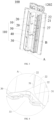
FIG. 3 is a schematic view of an air duct member of an air conditioner according to an embodiment of the present disclosure. -
FIG. 4 is an enlarged view of part A inFIG. 3 . -
FIG. 5 is an enlarged view of part B inFIG. 3 . -
FIG. 6 is a cross-sectional view of an air duct member of an air conditioner according to an embodiment of the present disclosure. -
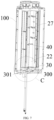
FIG. 7 is a schematic view of cooperation between an air duct member and a water receiving pan of an air conditioner according to an embodiment of the present disclosure. -
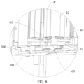
FIG. 8 is an enlarged view of part C inFIG. 7 . -
FIG. 9 is an assembled side view of an air duct member and a water receiving pan of an air conditioner according to an embodiment of the present disclosure. -
FIG. 10 is a partially enlarged view of the air duct member inFIG. 9 . - Embodiments of the present disclosure will be described in detail below with reference to examples thereof as illustrated in the accompanying drawings, throughout which same or similar elements, or elements having same or similar functions, are denoted by same or similar reference numerals. The embodiments described below with reference to the drawings are illustrative only, and are intended to explain, rather than limiting, the present disclosure.
- A number of embodiments or examples are provided below to implement different structures of the present disclosure. To simplify the disclosure of the present disclosure, components and arrangements of particular examples will be described below, which are examples only and are not intended to limit the present disclosure. Furthermore, reference numerals and/or reference letters may be repeated in different examples of the present disclosure. Such repetition is for the purpose of simplicity and clarity and does not indicate any relationship between various embodiments and/or arrangements in question. In addition, various examples of specific processes and materials are provided in the present disclosure. However, those of ordinary skill in the art may be aware of applications of other processes and/or the use of other materials.
- An
air duct member 101 according to an embodiment of the present disclosure will be described below with reference toFIG. 1 to FIG. 10 . Theair duct member 101 may be disposed at a ventilation and heat exchange component. The ventilation and heat exchange component may be disposed in anair conditioner 400. - As illustrated in
FIG. 1 to FIG. 8 , theair duct member 101 according to an embodiment of the present disclosure includes anair duct portion 10 and awater receiving portion 30. Theair duct portion 10 includes at least oneair duct structure 20. That is, theair duct portion 10 may have one or more theair duct structures 20. Further, theair duct portion 10 may include a plurality ofair duct structures 20. Theair duct structure 20 has a secondair duct wall 22 and a firstair duct wall 21. The secondair duct wall 22 and the firstair duct wall 21 are spaced apart from each other. Furthermore, the secondair duct wall 22 and the firstair duct wall 21 are opposite to each other and spaced apart from each other. Across-flow air duct 23 is defined between the secondair duct wall 22 and the firstair duct wall 21. An axis of thecross-flow air duct 23 may extend in a vertical direction. Thecross-flow air duct 23 extends in a height direction of theair duct member 101. The height direction of theair duct member 101 refers to an up-down direction inFIG. 3 . Anair duct inlet 24 of thecross-flow air duct 23 is defined between an end of the second air duct wall 22 (or an air duct wall joined to an end of the second air duct wall 22) and an end of the firstair duct wall 21. Theair duct inlet 24 is in communication with an interior of thecross-flow air duct 23. Anair duct outlet 25 of thecross-flow air duct 23 is defined between another end of the secondair duct wall 22 and another end of the firstair duct wall 21. Theair duct outlet 25 is in communication with the interior of thecross-flow air duct 23. The firstair duct wall 21 includes avolute tongue structure 26. Thevolute tongue structure 26 is disposed at the other end of the firstair duct wall 21. - Further, the
water receiving portion 30 is dispose at a lower end of theair duct portion 10. Further, thewater receiving portion 30 defines awater receiving recess 31 located outside thecross-flow air duct 23. Thewater receiving recess 31 has an open upper end and is located at a side of the secondair duct wall 22 away from the firstair duct wall 21. When there is condensed water on an outer surface of the secondair duct wall 22 away from the firstair duct wall 21, i.e., when there is condensed water on the outer surface of the secondair duct wall 22, the condensed water flows down along the outer surface of the secondair duct wall 22 by gravity. Since thewater receiving recess 31 is formed at the side of the secondair duct wall 22 away from the firstair duct wall 21, thewater receiving recess 31 may be adapted to receive the condensed water flowing down along the outer surface of the secondair duct wall 22. - In some embodiments, when the
air conditioner 400 is in a cooling mode, air inside thecross-flow air duct 23 has a low temperature. Since a temperature of an outer surface of theair duct structure 20 is approximately the same as an ambient temperature of an indoor space, a temperature of the outer surface of the secondair duct wall 22 is greater than the temperature of the air inside thecross-flow air duct 23. Due to such a temperature difference, water vapor in the air is formed into the condensed water on the outer surface of the secondair duct wall 22. Under the action of gravity, the condensed water flows down along the outer surface of the secondair duct wall 22. The condensed water may flow into thewater receiving recess 31 to avoid gathering of the condensed water on the outer surface of the secondair duct wall 22, which can keep the outer surface of the secondair duct wall 22 dry. In comparison with the related art, the condensed water generated on the outer surface of the secondair duct wall 22 can be collected without providing a thermal insulation layer such as a sponge at the outer surface of the secondair duct wall 22, which can avoid a situation that the sponge is susceptible to mould and bacterial growth after repeated dry-wet cycles over a long period of time. Therefore, it is possible to prevent theair duct member 101 from generating an unpleasant odour. In addition, a step of arranging the sponge at the outer surface of the secondair duct wall 22 is removed, which can simplify assembly steps of theair duct member 101 and save manpower. Also, materials and resources can be saved. - As a result, by arranging the
water receiving portion 30 at the lower end of theair duct portion 10, the condensed water flowing down along the outer surface of the secondair duct wall 22 may flow into thewater receiving recess 31. In comparison with the related art, there is no need to provide the thermal insulation layer such as the sponge on the outer surface of the secondair duct wall 22, which can avoid the situation that the sponge is susceptible to mould and bacterial growth after repeated dry-wet cycles over a long period of time. Therefore, it is possible to prevent theair duct member 101 from generating an unpleasant odour. In addition, the step of arranging the sponge at the outer surface of the secondair duct wall 22 is removed, which can simplify the assembly steps of theair duct member 101 and save manpower. Also, materials and resources can be saved. - In some embodiments of the present disclosure, the
air duct member 101 may be formed as a plastic member, which is low-cost and lightweight. In this way, manufacturing costs of theair duct member 101 can be lowered to reduce manufacturing costs of theair conditioner 400, enhancing market competitiveness of theair conditioner 400. In addition, a weight of theair duct member 101 can be lowered. When theair duct member 101 is mounted inside theair conditioner 400, a weight of theair conditioner 400 can be reduced, which can make theair conditioner 400 easy to be carried by a user and is conducive to a lightweight design of theair conditioner 400. - In some embodiments of the present disclosure, as illustrated in
FIG. 2 andFIG. 5 , theair duct portion 10 may include a leftair duct structure 20 and a rightair duct structure 20 arranged in a left-right direction of theair duct member 101. The left-right direction of theair duct member 101 is the same as a left-right direction of theair conditioner 400. Anair duct outlet 25 of the leftair duct structure 20 extends in a left front direction of theair duct member 101. Anair duct outlet 25 of the rightair duct structure 20 extends in a right front direction of theair duct member 101. Further, the leftair duct structure 20 and the rightair duct structure 20 are symmetrically arranged in a width direction of theair duct member 101. The width direction of theair duct member 101 refers to a left-right direction inFIG. 2 . The secondair duct wall 22 of the leftair duct structure 20 and the secondair duct wall 22 of the rightair duct structure 20 are located close to each other. The firstair duct wall 21 of the leftair duct structure 20 and the firstair duct wall 21 of the rightair duct structure 20 are located away from each other. The secondair duct wall 22 of each of the leftair duct structure 20 and the rightair duct structure 20 is located at a side of the firstair duct wall 21 close to the other one of the leftair duct structure 20 and the rightair duct structure 20. It should be noted that, as illustrated inFIG. 5 , the secondair duct wall 22 located at the leftair duct structure 20 is disposed at a right side of the firstair duct wall 21 of the leftair duct structure 20, and the secondair duct wall 22 located at the rightair duct structure 20 is disposed at a left side of the firstair duct wall 21 of the rightair duct structure 20. Thewater receiving recess 31 is located between lower ends of the secondair duct walls 22. That is, thewater receiving recess 31 is connected between the two secondair duct walls 22 of the leftair duct structure 20 and the rightair duct structure 20. In addition, thewater receiving recess 31 is disposed close to the lower end of the secondair duct wall 22. By forming thewater receiving recess 31 at the lower ends of the two secondair duct walls 22, the condensed water on the outer surfaces of the two secondair duct walls 22 can be ensured to flow into thewater receiving recess 31, which can avoid a short circuit in theair conditioner 400 caused when the condensed water on the outer surface of the secondair duct wall 22 flows to other parts in theair conditioner 400, enhancing use safety of theair conditioner 400, and further making thewater receiving recess 31 be formed at a reasonable position. - In some embodiments of the present disclosure, as illustrated in
FIG. 2 andFIG. 5 , theair duct outlet 25 of the leftair duct structure 20 extends in a left front direction of theair duct structure 20, and theair duct outlet 25 of the rightair duct structure 20 extends in a right front direction of theair duct structure 20. Thewater receiving recess 31 has afirst drainage hole 32. Thefirst drainage hole 32 may penetrate a bottom wall of thewater receiving recess 31, and is formed at a central position of thewater receiving recess 31 in a left-right direction. A bottom surface of thewater receiving recess 31 extends obliquely. Further, in a front-rear direction of theair duct member 101, the bottom surface of thewater receiving recess 31 extends obliquely downwards from front to rear. Furthermore, thefirst drainage hole 32 is formed close to a rear end of thewater receiving recess 31. When the condensed water flows into thewater receiving recess 31, the oblique arrangement of the bottom surface of thewater receiving recess 31 can facilitate a flow of the condensed water towards the rear end of thewater receiving recess 31, which can allow the condensed water to easily flow out of thewater receiving recess 31 through thefirst drainage hole 32. Therefore, it is possible to prevent the condensed water in thewater receiving recess 31 from overflowing thewater receiving recess 31. - In addition, since the
water receiving pan 301 in theair conditioner 400 is disposed below theheat exchange assembly 200 and is located close to the rear of theair conditioner 400, by forming thefirst drainage hole 32 close to the rear end of thewater receiving recess 31, the condensed water in thewater receiving recess 31 can flow downwardly and be discharged into thewater receiving pan 301 when the condensed water flows out of thefirst drainage hole 32. - In some embodiments of the present disclosure, as illustrated in
FIG. 3, FIG. 4 ,FIG. 5 , andFIG. 7 , a front end of thewater receiving recess 31 may have anavoidance notch 33 recessed rearwards, which may also be interpreted as that theavoidance notch 33 is formed at the front end of thewater receiving recess 31. In the front-rear direction of theair duct member 101, theavoidance notch 33 is recessed towards the rear end of thewater receiving recess 31. Theavoidance notch 33 can provide avoidance. Since a plurality of parts is disposed in theair conditioner 400, theavoidance notch 33 can allow thewater receiving recess 31 to avoid other parts in theair conditioner 400 to provide a mounting space for the other parts in theair conditioner 400. As a result, mounting of the other parts in theair conditioner 400 can be facilitated, and thus theair conditioner 400 has a compact structure. - In some embodiments of the present disclosure, as illustrated in
FIG. 3 andFIG. 6 , theair duct member 101 may further include asupport portion 40. Thesupport portion 40 is located between two adjacent secondair duct walls 22. That is, thesupport portion 40 is connected between the two adjacent secondair duct walls 22. In addition, thesupport portion 40 is configured to support the two secondair duct walls 22. Thesupport portion 40 may be spaced apart from thewater receiving recess 31 and located above thewater receiving recess 31. It should be noted that, thesupport portion 40 may be disposed above thewater receiving recess 31 and is spaced apart from thewater receiving recess 31. Thesupport portion 40 may have asecond drainage hole 41. Thesecond drainage hole 41 may be formed at an edge of thesupport portion 40. Through supporting the two adjacent secondair duct walls 22 by thesupport portion 40, structural strength of the secondair duct wall 22 can be enhanced to reinforce structural strength of theair duct structure 20, which can prevent the secondair duct wall 22 from being deformed. In addition, with thesecond drainage hole 41, when the condensed water on the outer surface of the secondair duct wall 22 flows to an upper surface of thesupport portion 40, the condensed water at the upper surface of thesupport portion 40 may flow downwards through thesecond drainage hole 41, in such a manner that the condensed water at the upper surface of thesupport portion 40 flows into thewater receiving recess 31, avoiding water accumulation at the upper surface of thesupport portion 40. - Further, a plurality of
support portions 40 may be provided between the two adjacent secondair duct walls 22. The plurality ofsupport portions 40 is sequentially arranged at intervals in the height direction of theair duct member 101. In addition, a constant spacing distance is formed between any twoadjacent support portions 40. By supporting the two adjacent secondair duct walls 22 by the plurality ofsupport portions 40 simultaneously, the structural strength of the secondair duct wall 22 can be further enhanced to further reinforce the structural strength of theair duct structure 20, preventing the secondair duct wall 22 from being deformed. - In some embodiments of the present disclosure, as illustrated in
FIG. 4 andFIG. 5 , the two secondair duct walls 22 are spaced apart from each other. As a result, a gap may be formed between the two secondair duct walls 22. Theair duct member 101 may further include aconnection portion 50. Theconnection portion 50 may be disposed in the gap between the two adjacent secondair duct walls 22 and is connected between the two adjacent secondair duct walls 22. Theconnection portion 50 is located at a rear side of thesupport portion 40 and extends in the height direction of theair duct member 101. A side of theconnection portion 50 is connected to one of the two adjacent secondair duct walls 22, while another side of theconnection portion 50 is connected to the other one of the two adjacent secondair duct walls 22. Theconnection portion 50 and the two secondair duct walls 22 may be integrally formed. Thesecond drainage hole 41 may be defined between a rear end of thesupport portion 50 and theconnection portion 50, which may also be interpreted as that thesecond drainage hole 41 may be formed between a front end of theconnection portion 50 and the rear end of thesupport portion 40. When the condensed water at the upper surface of thesupport portion 40 flows through thesecond drainage hole 41, the condensed water may flow downwardly into thewater receiving recess 31 along theconnection portion 50 to avoid splashing of the condensed water. Therefore, it is possible to further allow thesecond drainage hole 41 be formed at a reasonable position. - In some embodiments of the present disclosure, the
connection portion 50 may be formed into a plate-like structure, which can simplify a structure of theconnection portion 50 and facilitate production and manufacturing of theconnection portion 50. Further, a mould for manufacturing theconnection portion 50 can be simplified, and development costs of theconnection portion 50 can be reduced. - In some embodiments of the present disclosure, as illustrated in
FIG. 4 andFIG. 5 , the two adjacent secondair duct walls 22 are spaced apart from each other, and adrainage channel 51 may be defined between the air between theconnection portion 50 and the two secondair duct walls 22. Thedrainage channel 51 is configured to discharge water. Thedrainage channel 51 extends vertically. That is, thedrainage channel 51 extends in the height direction of theair duct member 101. Thesecond drainage hole 41 is in communication with thedrainage channel 51, and may discharge water towards thewater receiving recess 31 through thedrainage channel 51. When the condensed water at the upper surface of thesupport portion 40 flows through thesecond drainage hole 41, the condensed water may flow into thedrainage channel 51. The condensed water may flow downwardly into thewater receiving recess 31 along thedrainage channel 51 to be collected in thewater receiving recess 31. - In some embodiments of the present disclosure, as illustrated in
FIG. 5 , thesupport portion 40 may be provided with ahook 42. Thehook 42 is located at a front end of thesupport portion 40. In addition, thehook 42 may include asupport segment 421 extending transversely and a hookingsegment 422 extending upwards from thesupport segment 421. Thehook 42 is configured to hang parts. Theair conditioner 400 has an electric control box provided in theair conditioner 400. Thecross-flow air duct 23 may have across-flow fan wheel 1201 provided in thecross-flow air duct 23. Thecross-flow fan wheel 1201 is driven by amotor 1202 to rotate to allow an airflow to flow into thecross-flow air duct 23 through theair duct inlet 24, allowing the airflow in thecross-flow air duct 23 to flow out of thecross-flow air duct 23 from theair duct outlet 25. During mounting of the electric control box, the electric control box may be first hung at the hookingsegment 422 of thehook 42 and then removed from the hookingsegment 422 of thehook 42 after the electric control box is electrically connected to another part, e.g., after the electric control box is connected to themotor 1202 by a wire, and then the electric control box may be mounted at a designated region, realizing the mounting of the electric control box. With thehook 42, the mounting of the electric control box can be facilitated to save an operator's physical strength, increasing a mounting efficiency of the electric control box. - In some embodiments of the present disclosure, a
water collection recess 431 is defined in thesupport portion 40. Thesupport portion 40 may include aflow guide rib 432 disposed in thewater collection recess 431. Theflow guide rib 432 is configured to guide water in thewater collection recess 431 to flow towards thesecond drainage hole 41. Further, the upper surface of thesupport portion 40 may be provided with theflow guide rib 432. Theflow guide rib 432 can provide guiding for the condensed water. When the condensed water flows to the upper surface of thesupport portion 40, theflow guide rib 432 can facilitate a flow of the condensed water at the upper surface of thesupport portion 40 towards thesecond drainage hole 41, which facilitates discharge of the condensed water at the upper surface of thesupport portion 40. - In some embodiments of the present disclosure, as illustrated in
FIG. 3 , the secondair duct wall 22 may be provided with acable holder 27. A plurality ofcable holders 27 may be provided and arranged at intervals in a height direction of the secondair duct wall 22. For example, the plurality ofcable holders 27 may be arranged in a plurality of columns, andseveral cable holders 27 may be included in each column. Further, one secondair duct wall 22 is provided with one column ofcable holders 27. Each column ofcable holders 27 may include threecable holders 27. The threecable holders 27 are sequentially arranged at intervals in the height direction of the secondair duct wall 22. - When a wire harness (wire) is arranged between the two adjacent second
air duct walls 22, mounting the wire harness at thecable holder 27 can prevent the wire harness from being brought into contact with the outer surface of the secondair duct wall 22 to avoid a short-circuit of the wire harness caused when the wire harness encounters the condensed water. Therefore, the use safety of theair conditioner 400 can be increased. Further, after the electronic control box is connected to themotor 1202 by the wire harness, mounting the wire harness at thecable holder 27 can prevent the wire harness from being brought into contact with the outer surface of the secondair duct wall 22. - In some embodiments of the present disclosure, the
water receiving portion 30 and at least part of a structure of the secondair duct wall 22 may be integrally formed. Further, thewater receiving portion 30 and the two adjacent secondair duct walls 22 are integrally formed. In this way, overall structural strength of thewater receiving portion 30 and theair duct structure 20 can be enhanced, and the number of moulds developed for manufacturing theair duct member 101 can be reduced to lower development costs of theair duct member 101. As a result, development costs of theair conditioner 400 can be reduced. - In some embodiments of the present disclosure, as illustrated in
FIG. 10 , thewater receiving recess 31 may have afirst drainage hole 32, and the bottom surface of thewater receiving recess 31 extends obliquely. Further, the bottom surface of thewater receiving recess 31 extends obliquely downwards towards thefirst drainage hole 32. By arranging the bottom surface of thewater receiving recess 31 obliquely, when there is the condensed water in thewater receiving recess 31, the condensed water in thewater receiving recess 31 can easily flow into thefirst drainage hole 32, which can avoid accumulation of the condensed water in thewater receiving recess 31. Therefore, it is possible to prevent the condensed water in thewater receiving recess 31 from overflowing thewater receiving recess 31. - In some embodiments of the present disclosure, an angle of the bottom surface of the
water receiving recess 31 relative to a horizontal plane may be set to be β, which satisfies a relational expression: 1°≤β≤5°. In this way, the bottom surface of thewater receiving recess 31 may be inclined at an appropriate angle, which helps the condensed water flow into thefirst drainage hole 32 and allows the condensed water to flow in thewater receiving recess 31 at an appropriate speed. Therefore, the accumulation of the condensed water in thewater receiving recess 31 can be further avoided. - Further, the angle β of the bottom surface of the
water receiving recess 31 relative to the horizontal plane may be set to be 3°. In this way, the bottom surface of thewater receiving recess 31 may be inclined at a more appropriate angle, which further helps the condensed water flow into thefirst drainage hole 32 and allows the condensed water to flow in thewater receiving recess 31 at a more appropriate speed. Therefore, the accumulation of the condensed water in thewater receiving recess 31 can be further avoided, which in turn achieves an appropriate angle of the bottom surface of thewater receiving recess 31 relative to the horizontal surface. - In some embodiments of the present disclosure, as illustrated in
FIG. 10 , theair duct member 101 may further include aflow guide portion 60. Theflow guide portion 60 may be located below thewater receiving recess 31 and define aflow guide channel 61. It should be noted that theflow guide channel 61 may be defined in theflow guide portion 60. Theflow guide channel 61 has an open upper end. The upper end of theflow guide channel 61 may be in communication with thefirst drainage hole 32. A lower end of theflow guide channel 61 may have athird drainage hole 62. Thethird drainage hole 62 may be located below thefirst drainage hole 32, and offset from thefirst drainage hole 32 in a horizontal direction. It should be noted that thefirst drainage hole 32 and theflow guide channel 61 may directly face towards each other from top to bottom, and thethird drainage hole 62 and thefirst drainage hole 32 do not directly face towards each other from top to bottom. For example, thethird drainage hole 62 is formed below thefirst drainage hole 32. In addition, thethird drainage hole 62 is located at a rear side of thefirst drainage hole 32 directly below thefirst drainage hole 32. Thethird drainage hole 62 and thewater receiving pan 301 directly faces towards each other from top to bottom. When there is the condensed water in thewater receiving recess 31, the condensed water in thewater receiving recess 31 flows downwardly into theflow guide channel 61 through thefirst drainage hole 32, then the condensed water in theflow guide channel 61 flows into thewater receiving pan 301 through thethird drainage hole 62, and finally the condensed water in thewater receiving pan 301 is discharged through a drainage pipe of thewater receiving pan 301. - In some embodiments of the present disclosure, a plurality of first drainage holes 32 may be formed at the
water receiving recess 31. The plurality of first drainage holes 32 are formed at intervals at thewater receiving recess 31. The upper end of theflow guide channel 61 may be in communication with each of the plurality of first drainage holes 32. Each of the plurality of first drainage holes 32 and theflow guide channel 61 may directly face towards each other from top and bottom. Thethird drainage hole 62 and the plurality of first drainage holes 32 do not directly face towards each other from top and bottom. For example, thethird drainage hole 62 is formed below the plurality of first drainage holes 32 and is located at the rear side of thefirst drainage hole 32 directly below thefirst drainage hole 32. When there is the condensed water in thewater receiving recess 31, the condensed water in thewater receiving recess 31 flows downwardly into theflow guide channel 61 through the plurality of first drainage holes 32 simultaneously, and then the condensed water in theflow guide channel 61 flows into thewater receiving pan 301 through thethird drainage hole 62. In this way, a discharge efficiency of the condensed water in thewater receiving recess 31 can be improved, and a discharge volume of thewater receiving recess 31 per unit of time can be increased, thereby effectively avoiding an overflow of the condensed water in thewater receiving recess 31. - In some embodiments of the present disclosure, a first outlet grille (not illustrated) may be disposed at the
air duct outlet 25. When the airflow is blown out from theair duct outlet 25, the first outlet grille can allow the airflow to be uniformly blown out from theair duct outlet 25, which can enhance comfort of air blowing. - As illustrated in
FIG. 2 ,FIG. 3 , andFIG. 9 , a ventilation and heat exchange component according to an embodiment of the present disclosure includes aventilation assembly 100, aheat exchange assembly 200, and awater receiving assembly 300. Theventilation assembly 100 includes theair duct member 101 according to any of the above embodiments and afan 102. Thefan 102 includes thecross-flow fan wheel 1201 and themotor 1202. Thecross-flow fan wheel 1201 is disposed in thecross-flow air duct 23. Themotor 1202 is configured to drive thecross-flow fan wheel 1201 to rotate in thecross-flow air duct 23. Theheat exchange assembly 200 is disposed upstream of theair duct outlet 25. In a flowing direction of the airflow, theheat exchange assembly 200 is disposed upstream of theair duct outlet 25. That is, theheat exchange assembly 200 is disposed at a rear side of theair duct outlet 25. Theheat exchange assembly 200 may include aheat exchanger 203 and an electricauxiliary heater 204. Theheat exchanger 203 serves as an evaporator in a cooling mode and serves as a condenser in a heating mode. The electricauxiliary heater 204 may be switched on in the heating mode. The switched-on electricauxiliary heater 204 may heat the air flowing into theair conditioner 400 to assist in heating. In the cooling mode, the electricauxiliary heater 204 is switched off, i.e., the electricauxiliary heater 204 is in no operation. Thewater receiving assembly 300 includes thewater receiving pan 301 according to any of the above embodiments. Thewater receiving pan 301 may be disposed below theheat exchange assembly 200, and is adapted to receive the condensed water flowing down along theheat exchange assembly 200 and drainage water from thewater receiving recess 31. In the cooling mode, there is also the condensed water on an outer surface of the electricauxiliary heater 204. The condensed water on the electricauxiliary heater 204 flows into thewater receiving pan 301 below the electricauxiliary heater 204, and the condensed water in thewater receiving pan 301 is discharged through the drainage pipe of thewater receiving pan 301. In this way, it is possible to prevent the condensed water from accumulating in large quantities in thewater receiving pan 301, to avoid a short circuit in theair conditioner 400 resulted when the condensed water overflows thewater receiving pan 301. Therefore, the use safety of theair conditioner 400 can be ensured. - As a result, by arranging the
water receiving portion 30 at the lower end of theair duct portion 10, the condensed water flowing down along the outer surface of the secondair duct wall 22 may flow into thewater receiving recess 31. In comparison with the related art, there is no need to provide a thermal insulation layer such as a sponge on the outer surface of the secondair duct wall 22, which can avoid the situation that the sponge is susceptible to mould and bacterial growth after repeated dry-wet cycles over a long period of time. Therefore, it is possible to prevent theair duct member 101 from generating an unpleasant odour. In addition, the step of arranging the sponge at the outer surface of the secondair duct wall 22 is removed, which can simplify the assembly steps of theair duct member 101 and save manpower. Also, materials and resources can be saved. - In some embodiments of the present disclosure, the
air duct member 101 includes theflow guide portion 60. Thewater receiving pan 301 may be located at a rear side of thewater receiving portion 30 below thewater receiving portion 30. Thethird drainage hole 62 is located at a rear side of thefirst drainage hole 32 below thefirst drainage hole 32 and located directly above thewater receiving pan 301. In this way, the flow of the condensed water into thewater receiving pan 301 can be facilitated. - According to an embodiment of the present disclosure, an
air conditioner 400 includes the ventilation and heat exchange component according to any of the above embodiments and amachine body 401. Themachine body 401 has anair inlet 402 and anair outlet 403. Aninlet grille 404 is mounted at theair inlet 402. Theheat exchange assembly 200 may be disposed behind theair duct member 101. The ventilation and heat exchange component is disposed in themachine body 401. Theair duct inlet 24 is in communication with theair inlet 402. Theair outlet 403 is in communication with theair duct outlet 25. By arranging thewater receiving portion 30 at the lower end of theair duct portion 10, the condensed water flowing down along the outer surface of the secondair duct wall 22 may flow into thewater receiving recess 31. In comparison with the related art, there is no need to provide a thermal insulation layer such as a sponge on the outer surface of the secondair duct wall 22, which can avoid the situation that the sponge is susceptible to mould and bacterial growth after repeated dry-wet cycles over a long period of time. Therefore, it is possible to prevent theair duct member 101 from generating an unpleasant odour, and effectively avoid an unpleasant odour in the air blown by theair conditioner 400. In addition, the step of arranging the sponge at the outer surface of the secondair duct wall 22 is removed, which can simplify the assembly steps of theair duct member 101 and save manpower. Also, materials and resources can be saved. Therefore, the manufacturing costs of theair conditioner 400 can be lowered, and an assembly efficiency of theair conditioner 400 can be improved. - In some embodiments of the present disclosure, a second outlet grille (not illustrated) may be disposed at the
air outlet 403. The airflow flows to theair outlet 403 when blown out from theair duct outlet 25. When the airflow flows through theair outlet 403, the second outlet grille can allow the air to be blown uniformly to an indoor environment from theair outlet 403, which further improves the comfort of air blowing. - Further, the
air outlet 403 may be provided with a humidification module at an inner side of theair outlet 403. Before the air flows through theair outlet 403, the humidification module can humidify the air. The humidified air is blown from theair outlet 403 to the indoor environment. In this way, humidity of the air blown out by theair conditioner 400 can be increased to keep the indoor environment at appropriate humidity, thereby improving comfort for the user. Further, an air purification module may be provided at theair outlet 403 and/or theair duct outlet 25. Before the air flows through theair outlet 403 and/or theair duct outlet 25, the air purification module can purify the air to make the air blown into the indoor environment clean, which can prevent the air blown out by theair conditioner 400 from polluting the indoor environment, thereby ensuring the health of the user. - Each of the humidification module and the air purification module may be connected to a controller of the
air conditioner 400. The controller can be configured to control operation of each of the humidification module and the air purification module. When the humidification module and/or the air purification module is required to be in operation, the controller controls the humidification module and/or the air purification module to operate. When the humidification module and/or the air purification module are not required to be in operation, the controller controls the humidification module and/or the air purification module to stop operation. Further, theair conditioner 400 may be provided with a control button. An operation mode of theair conditioner 400 may be adjusted by the user by means of the control button. When the humidification module is required to be in operation, the user may press the control button to make the controller control the humidification module to operate. When the air purification module is required to be in operation, the user may press the control button to make the controller control the air purification module to operate. - It should be noted that the
machine body 401 may further include anair outlet frame 405 and a base. Theair outlet 403 may be formed at theair outlet frame 405 and may be selectively covered or exposed. Theair outlet frame 405 may be provided with a front panel at a front side of theair outlet frame 405. The front panel may be movably disposed at theair outlet frame 405 and configured to block theair outlet 403 to cover theair outlet 403. When theair conditioner 400 is required to blow air outwards, theair conditioner 400 controls a driving device to drive the front panel to move to keep the front panel away from theair outlet 403. In this case, theair outlet 403 is in an exposed state. Theair conditioner 400 may blow the air towards an outer side from theair outlet 403 to meet the user's needs. When there is no need for theair conditioner 400 to blow the air outwards, theair conditioner 400 controls the driving device to drive the front panel to move to allow the front panel to cover theair outlet 403. In this case, theair outlet 403 is in a covered state. Theair conditioner 400 does not blow the air towards the outer side from theair outlet 403. Covering theair outlet 403 by the front panel can prevent objects such as dust and bugs from moving from theair outlet 403 to an inside of theair conditioner 400 when theair conditioner 400 is not in use, ensuring cleanliness inside theair conditioner 400 and the use safety of theair conditioner 400. - Further, the base may be disposed at a lowermost end of the
air conditioner 400. The base is configured to support theair conditioner 400 to place theair conditioner 400 on the ground stably, which can prevent theair conditioner 400 from tipping over. Therefore, the use safety of theair conditioner 400 is ensured, and service life of theair conditioner 400 is prolonged. - In the description of the present disclosure, it should be understood that, the orientation or the position indicated by terms such as "center", "longitudinal", "lateral", "length", "width", "thickness", "over", "below", "front", "rear", "left", "right", "vertical", "horizontal", "top", "bottom", "inner", "outer", "clockwise", "anti-clockwise", "axial", "radial", and "circumferential" should be construed to refer to the orientation and the position as shown in the drawings, and is only for the convenience of describing the present disclosure and simplifying the description, rather than indicating or implying that the pointed device or element must have a specific orientation, or be constructed and operated in a specific orientation, and therefore cannot be understood as a limitation of the present disclosure.
- In addition, terms "first" and "second" are only used for descriptive purposes, and cannot be understood as indicating or implying relative importance or implicitly indicating the number of the indicated technical features. Therefore, the features associated with "first" and "second" may explicitly or implicitly include at least one of the features. In the description of the present disclosure, "plurality" means at least two, unless otherwise specifically defined.
- In the present disclosure, unless otherwise clearly specified and limited, terms such as "install", "connect", "connect to", "fix" and the like should be understood in a broad sense. For example, it may be a fixed connection or a detachable connection or connection as one piece; mechanical connection or electrical connection or communication; direct connection or indirect connection through an intermediate; internal communication of two components or the interaction relationship between two components. For those of ordinary skill in the art, the specific meaning of the above-mentioned terms in the present disclosure can be understood according to specific circumstances.
- In the present disclosure, unless expressly stipulated and defined otherwise, the first feature "on" or "under" the second feature may mean that the first feature is in direct contact with the second feature, or the first and second features are in indirect contact through an intermediate. Moreover, the first feature "above" the second feature may mean that the first feature is directly above or obliquely above the second feature, or simply mean that the level of the first feature is higher than that of the second feature. The first feature "below" the second feature may mean that the first feature is directly below or obliquely below the second feature, or simply mean that the level of the first feature is smaller than that of the second feature.
- Reference throughout this specification to "an embodiment", "some embodiments", "an example", "a specific example", or "some examples" means that a particular feature, structure, material, or characteristic described in connection with the embodiment or example is included in at least one embodiment or example of the present disclosure. The appearances of the above phrases in various places throughout this specification are not necessarily referring to the same embodiment or example. Furthermore, the particular features, structures, materials, or characteristics may be combined in any suitable manner in one or more embodiments or examples. In addition, different embodiments or examples and features of different embodiments or examples described in the specification may be combined by those skilled in the art without mutual contradiction.
- Although embodiments of the present disclosure have been illustrated and described, it is conceivable for those of ordinary skill in the art that various changes, modifications, replacements, and variations can be made to these embodiments without departing from the principles of the present disclosure. The scope of the present disclosure shall be defined by the claims as appended and their equivalents.
Claims (16)
- An air duct member, characterized by:an air duct portion comprising at least one air duct structure, the at least one air duct structure having a first air duct wall and a second air duct wall spaced apart from each other, a cross-flow air duct being defined between the first air duct wall and the second air duct wall, and the first air duct wall comprising a volute tongue structure; anda water receiving portion disposed at a lower end of the air duct portion and defining a water receiving recess located outside the cross-flow air duct, the water receiving recess being located at a side of the second air duct wall away from the first air duct wall and adapted to receive condensed water flowing down along an outer surface of the second air duct wall.
- The air duct member according to claim 1, wherein the air duct portion comprises a left air duct structure and a right air duct structure arranged in a left-right direction, wherein:the left air duct structure has an air duct outlet extending in a left front direction;the right air duct structure has an air duct outlet extending in a right front direction;the second air duct wall of the left air duct structure and the second air duct wall of the right air duct structure are located close to each other;the first air duct wall of the left air duct structure and the first air duct wall of the right air duct structure are located away from each other; andthe water receiving recess is located between lower ends of the two second air duct walls.
- The air duct member according to claim 2, wherein:the water receiving recess has a first drainage hole located at a central position in the left-right direction; anda bottom surface of the water receiving recess extends obliquely downwards from front to rear.
- The air duct member according to claim 3, wherein a front end of the water receiving recess has an avoidance notch recessed rearwards.
- The air duct member according to claim 2, further comprising a support portion located between the two second air duct walls and configured to support the two second air duct walls, wherein:the support portion is spaced apart from the water receiving recess and located above the water receiving recess; andan edge of the support portion has a second drainage hole.
- The air duct member according to claim 5, wherein:the two second air duct walls are spaced apart from each other to form a gap between the two second air duct walls;the air duct member further comprises a connection portion disposed in the gap between the two second air duct walls and connecting the two second air duct walls, the connection portion being located at a rear side of the support portion; andthe second drainage hole is defined between a rear end of the support portion and the connection portion.
- The air duct member according to claim 6, wherein a drainage channel is defined between the connection portion and the gap between the two second air duct walls and extends vertically, the second drainage hole being configured to discharge water towards the water receiving recess through the drainage channel.
- The air duct member according to claim 5, wherein the support portion is provided with a hook located at a front end of the support portion, the hook comprising a support segment extending transversely and a hooking segment extending upwards from the support segment.
- The air duct member according to claim 5, wherein:a water collection recess is defined in the support portion; andthe support portion comprises a flow guide rib disposed in the water collection recess, the flow guide rib being configured to guide water in the water collection recess to flow towards the second drainage hole.
- The air duct member according to any one of claims 1 to 9, wherein the second air duct wall is provided with a cable holder.
- The air duct member according to any one of claims 1 to 10, wherein the water receiving portion and at least part of the second air duct wall are integrally formed.
- The air duct member according to any one of claims 1 to 11, wherein:the water receiving recess has a first drainage hole; anda bottom surface of the water receiving recess extends obliquely downwards towards the first drainage hole.
- The air duct member according to claim 3 or 12, further comprising:
a flow guide portion located below the water receiving recess and defining a flow guide channel, the flow guide channel having an upper end in communication with the first drainage hole and a lower end having a third drainage hole, the third drainage hole being located below the first drainage hole and offset from the first drainage hole in a horizontal direction. - A ventilation and heat exchange component, comprising:a ventilation assembly comprising the air duct member according to any one of claims 1 to 13 and a fan, the fan comprising a cross-flow fan wheel disposed at the cross-flow air duct;a heat exchange assembly disposed upstream of an air duct outlet; anda water receiving assembly comprising a water receiving pan disposed below the heat exchange assembly, the water receiving pan being adapted to receive condensed water flowing down along the heat exchange assembly and drainage water from the water receiving recess.
- The ventilation and heat exchange component according to claim 14, wherein:the air duct member comprises a flow guide portion;the water receiving pan is located at a rear side of the water receiving portion below the water receiving portion; anda third drainage hole is located at a rear side of a first drainage hole below the first drainage hole, and arranged directly above the water receiving pan.
- An air conditioner, comprising:a machine body having an air inlet and an air outlet; andthe ventilation and heat exchange component according to claim 14 or 15, the ventilation and heat exchange component being disposed in the machine body, wherein:the air inlet is in communication with an air duct inlet; andthe air outlet is in communication with an air duct outlet.
Applications Claiming Priority (3)
| Application Number | Priority Date | Filing Date | Title |
|---|---|---|---|
| CN202110632637.2A CN115507532A (en) | 2021-06-07 | 2021-06-07 | Air duct piece, ventilation and heat exchange part and air conditioner |
| CN202121268886.XU CN215909348U (en) | 2021-06-07 | 2021-06-07 | Air duct piece, ventilation and heat exchange component and air conditioner |
| PCT/CN2022/096297 WO2022257820A1 (en) | 2021-06-07 | 2022-05-31 | Air duct member, ventilation and heat exchange component, and air conditioner |
Publications (2)
| Publication Number | Publication Date |
|---|---|
| EP4336117A1 true EP4336117A1 (en) | 2024-03-13 |
| EP4336117A4 EP4336117A4 (en) | 2024-09-11 |
Family
ID=84424638
Family Applications (1)
| Application Number | Title | Priority Date | Filing Date |
|---|---|---|---|
| EP22819418.9A Pending EP4336117A4 (en) | 2021-06-07 | 2022-05-31 | Air duct member, ventilation and heat exchange component, and air conditioner |
Country Status (3)
| Country | Link |
|---|---|
| US (1) | US20240117973A1 (en) |
| EP (1) | EP4336117A4 (en) |
| WO (1) | WO2022257820A1 (en) |
Families Citing this family (1)
| Publication number | Priority date | Publication date | Assignee | Title |
|---|---|---|---|---|
| CN119860564B (en) * | 2023-10-20 | 2026-02-27 | 青岛海尔空调器有限总公司 | Indoor unit of floor air conditioner |
Family Cites Families (12)
| Publication number | Priority date | Publication date | Assignee | Title |
|---|---|---|---|---|
| CN106705232B (en) * | 2014-03-31 | 2019-08-09 | 美的集团股份有限公司 | vertical air conditioner indoor unit |
| CN104296343A (en) * | 2014-09-26 | 2015-01-21 | 广州华凌制冷设备有限公司 | Wind blocking piece, air flue assembly and vertical air conditioner indoor unit |
| CN104807109A (en) * | 2015-05-08 | 2015-07-29 | 珠海格力电器股份有限公司 | Air conditioner |
| CN204901963U (en) * | 2015-07-31 | 2015-12-23 | 芜湖美智空调设备有限公司 | Two through -flow cabinet -type air conditioners |
| CN105352040B (en) * | 2015-11-30 | 2018-10-23 | 广东美的制冷设备有限公司 | Cabinet air-conditioner |
| CN206803443U (en) * | 2017-06-19 | 2017-12-26 | 奥克斯空调股份有限公司 | A kind of air channel structure of air conditioner |
| CN107388364B (en) * | 2017-07-27 | 2023-04-28 | 青岛海尔空调器有限总公司 | An air conditioner and its water tray device |
| CN107366964A (en) * | 2017-07-27 | 2017-11-21 | 青岛海尔空调器有限总公司 | A kind of vertical air conditioner and its air channel |
| CN210153949U (en) * | 2019-06-25 | 2020-03-17 | 宁波奥克斯电气股份有限公司 | Water receiving tray for vertical air conditioner and air conditioner |
| CN210861425U (en) * | 2019-10-31 | 2020-06-26 | 广东美的制冷设备有限公司 | Mobile air conditioner |
| CN211345786U (en) * | 2019-12-05 | 2020-08-25 | 青岛海尔空调器有限总公司 | Water pan and air conditioner indoor unit with same |
| CN215909348U (en) * | 2021-06-07 | 2022-02-25 | 美的集团股份有限公司 | Air duct piece, ventilation and heat exchange component and air conditioner |
-
2022
- 2022-05-31 EP EP22819418.9A patent/EP4336117A4/en active Pending
- 2022-05-31 WO PCT/CN2022/096297 patent/WO2022257820A1/en not_active Ceased
-
2023
- 2023-12-05 US US18/529,503 patent/US20240117973A1/en active Pending
Also Published As
| Publication number | Publication date |
|---|---|
| EP4336117A4 (en) | 2024-09-11 |
| US20240117973A1 (en) | 2024-04-11 |
| WO2022257820A1 (en) | 2022-12-15 |
Similar Documents
| Publication | Publication Date | Title |
|---|---|---|
| CN113701334B (en) | Wall-mounted air conditioner indoor unit | |
| US20240117973A1 (en) | Air duct member, ventilation and heat exchange component, and air conditioner | |
| CN212719963U (en) | Integrated dry type fan coil | |
| CN211345777U (en) | Chassis shell and window type air conditioner | |
| CN113701335B (en) | Wall-mounted air conditioner indoor unit | |
| CN215909348U (en) | Air duct piece, ventilation and heat exchange component and air conditioner | |
| CN1097198C (en) | Air conditioner | |
| CN214841231U (en) | Wall-mounted air conditioner indoor unit | |
| CN102141270B (en) | Window-type air conditioner | |
| CN115507532A (en) | Air duct piece, ventilation and heat exchange part and air conditioner | |
| CN112325390B (en) | Mobile Air Conditioning | |
| CN218001666U (en) | Air duct machine | |
| JP2007210360A (en) | Air conditioner | |
| CN214949372U (en) | Humidification device and air conditioning system with same | |
| CN216620025U (en) | Air conditioner | |
| JP2009041542A (en) | Electric fan device | |
| CN224033910U (en) | air conditioner | |
| CN219389905U (en) | Indoor unit of vertical air conditioner and vertical air conditioner with indoor unit | |
| CN211290678U (en) | Small refrigerator with dry inner cavity | |
| CN210292082U (en) | Machine and air conditioner in air conditioning | |
| CN201110606Y (en) | Indoor machine of air conditioner | |
| CN115143532A (en) | Wall-mounted air conditioner indoor unit | |
| CN210861408U (en) | Air conditioner | |
| CN215062477U (en) | Humidification device and air conditioning system with same | |
| CN218495348U (en) | Drainage device of air conditioner |
Legal Events
| Date | Code | Title | Description |
|---|---|---|---|
| STAA | Information on the status of an ep patent application or granted ep patent |
Free format text: STATUS: THE INTERNATIONAL PUBLICATION HAS BEEN MADE |
|
| PUAI | Public reference made under article 153(3) epc to a published international application that has entered the european phase |
Free format text: ORIGINAL CODE: 0009012 |
|
| STAA | Information on the status of an ep patent application or granted ep patent |
Free format text: STATUS: REQUEST FOR EXAMINATION WAS MADE |
|
| 17P | Request for examination filed |
Effective date: 20231208 |
|
| AK | Designated contracting states |
Kind code of ref document: A1 Designated state(s): AL AT BE BG CH CY CZ DE DK EE ES FI FR GB GR HR HU IE IS IT LI LT LU LV MC MK MT NL NO PL PT RO RS SE SI SK SM TR |
|
| A4 | Supplementary search report drawn up and despatched |
Effective date: 20240808 |
|
| DAV | Request for validation of the european patent (deleted) | ||
| DAX | Request for extension of the european patent (deleted) | ||
| RIC1 | Information provided on ipc code assigned before grant |
Ipc: F24F 13/22 20060101ALI20240802BHEP Ipc: F24F 1/0093 20190101ALI20240802BHEP Ipc: F24F 1/0063 20190101ALI20240802BHEP Ipc: F24F 13/02 20060101AFI20240802BHEP |