EP4336071A1 - Method for estimating a valve characteristic for an actuator system of a work vehicle transmission - Google Patents
Method for estimating a valve characteristic for an actuator system of a work vehicle transmission Download PDFInfo
- Publication number
- EP4336071A1 EP4336071A1 EP23195876.0A EP23195876A EP4336071A1 EP 4336071 A1 EP4336071 A1 EP 4336071A1 EP 23195876 A EP23195876 A EP 23195876A EP 4336071 A1 EP4336071 A1 EP 4336071A1
- Authority
- EP
- European Patent Office
- Prior art keywords
- actuator system
- electronic control
- control unit
- seats
- shaft
- Prior art date
- Legal status (The legal status is an assumption and is not a legal conclusion. Google has not performed a legal analysis and makes no representation as to the accuracy of the status listed.)
- Withdrawn
Links
- 238000000034 method Methods 0.000 title claims abstract description 28
- 230000005540 biological transmission Effects 0.000 title claims description 28
- 238000012512 characterization method Methods 0.000 claims abstract description 18
- 238000006073 displacement reaction Methods 0.000 claims 1
- 230000033001 locomotion Effects 0.000 description 7
- 230000004913 activation Effects 0.000 description 3
- 230000006835 compression Effects 0.000 description 3
- 238000007906 compression Methods 0.000 description 3
- 238000012986 modification Methods 0.000 description 2
- 230000004048 modification Effects 0.000 description 2
- 230000007935 neutral effect Effects 0.000 description 2
- 230000000694 effects Effects 0.000 description 1
- 239000012530 fluid Substances 0.000 description 1
- 239000002783 friction material Substances 0.000 description 1
- 238000009434 installation Methods 0.000 description 1
- 238000012423 maintenance Methods 0.000 description 1
- 238000013507 mapping Methods 0.000 description 1
Images

Classifications
-
- F—MECHANICAL ENGINEERING; LIGHTING; HEATING; WEAPONS; BLASTING
- F16—ENGINEERING ELEMENTS AND UNITS; GENERAL MEASURES FOR PRODUCING AND MAINTAINING EFFECTIVE FUNCTIONING OF MACHINES OR INSTALLATIONS; THERMAL INSULATION IN GENERAL
- F16H—GEARING
- F16H61/00—Control functions within control units of change-speed- or reversing-gearings for conveying rotary motion ; Control of exclusively fluid gearing, friction gearing, gearings with endless flexible members or other particular types of gearing
- F16H61/26—Generation or transmission of movements for final actuating mechanisms
- F16H61/28—Generation or transmission of movements for final actuating mechanisms with at least one movement of the final actuating mechanism being caused by a non-mechanical force, e.g. power-assisted
- F16H61/2807—Generation or transmission of movements for final actuating mechanisms with at least one movement of the final actuating mechanism being caused by a non-mechanical force, e.g. power-assisted using electric control signals for shift actuators, e.g. electro-hydraulic control therefor
-
- F—MECHANICAL ENGINEERING; LIGHTING; HEATING; WEAPONS; BLASTING
- F16—ENGINEERING ELEMENTS AND UNITS; GENERAL MEASURES FOR PRODUCING AND MAINTAINING EFFECTIVE FUNCTIONING OF MACHINES OR INSTALLATIONS; THERMAL INSULATION IN GENERAL
- F16H—GEARING
- F16H61/00—Control functions within control units of change-speed- or reversing-gearings for conveying rotary motion ; Control of exclusively fluid gearing, friction gearing, gearings with endless flexible members or other particular types of gearing
- F16H61/26—Generation or transmission of movements for final actuating mechanisms
- F16H61/28—Generation or transmission of movements for final actuating mechanisms with at least one movement of the final actuating mechanism being caused by a non-mechanical force, e.g. power-assisted
- F16H2061/283—Adjustment or calibration of actuator positions, e.g. neutral position
-
- F—MECHANICAL ENGINEERING; LIGHTING; HEATING; WEAPONS; BLASTING
- F16—ENGINEERING ELEMENTS AND UNITS; GENERAL MEASURES FOR PRODUCING AND MAINTAINING EFFECTIVE FUNCTIONING OF MACHINES OR INSTALLATIONS; THERMAL INSULATION IN GENERAL
- F16H—GEARING
- F16H2342/00—Calibrating
- F16H2342/02—Calibrating shift or range movements
-
- F—MECHANICAL ENGINEERING; LIGHTING; HEATING; WEAPONS; BLASTING
- F16—ENGINEERING ELEMENTS AND UNITS; GENERAL MEASURES FOR PRODUCING AND MAINTAINING EFFECTIVE FUNCTIONING OF MACHINES OR INSTALLATIONS; THERMAL INSULATION IN GENERAL
- F16H—GEARING
- F16H2342/00—Calibrating
- F16H2342/10—Calibrating valves
-
- F—MECHANICAL ENGINEERING; LIGHTING; HEATING; WEAPONS; BLASTING
- F16—ENGINEERING ELEMENTS AND UNITS; GENERAL MEASURES FOR PRODUCING AND MAINTAINING EFFECTIVE FUNCTIONING OF MACHINES OR INSTALLATIONS; THERMAL INSULATION IN GENERAL
- F16H—GEARING
- F16H59/00—Control inputs to control units of change-speed- or reversing-gearings for conveying rotary motion
- F16H59/68—Inputs being a function of gearing status
-
- F—MECHANICAL ENGINEERING; LIGHTING; HEATING; WEAPONS; BLASTING
- F16—ENGINEERING ELEMENTS AND UNITS; GENERAL MEASURES FOR PRODUCING AND MAINTAINING EFFECTIVE FUNCTIONING OF MACHINES OR INSTALLATIONS; THERMAL INSULATION IN GENERAL
- F16H—GEARING
- F16H63/00—Control outputs from the control unit to change-speed- or reversing-gearings for conveying rotary motion or to other devices than the final output mechanism
- F16H63/02—Final output mechanisms therefor; Actuating means for the final output mechanisms
- F16H63/30—Constructional features of the final output mechanisms
- F16H63/38—Detents
Definitions
- the present invention concerns a method for estimating a valve characteristic, in particular a method for estimating a valve characteristic for an actuator system of a work vehicle transmission such as an agricultural vehicle.
- the present invention finds its preferred, although not exclusive, application in transmission for a work vehicle. Reference will be made to this application by way of example below.
- Transmission architectures for work vehicles such as agricultural vehicles use synchronizer elements configured to engage or disengage shafts of the transmission.
- power shift transmission use a large number of such synchronizer elements.
- Such transmission architecture comprise hydraulic actuators configured to apply a force to the parts of the synchronizer elements in order to engage or disengage the elements connectable by this latter.
- force is controlled by electro-actuated valves that regulate the passage of actuation fluid.
- known transmission architectures do not comprise pressure sensor configured to detect pressure of the activation of such electro valves.
- valve current-pressure characteristics can be assumed linear with the same slope for all valves, the current need to activate the valve can be different.
- An aim of the present invention is to satisfy the above mentioned needs in a cost-effective and optimized manner.
- FIG 1 it is partially shown an actuator system 1 for a synchronizer element 2 for a transmission architecture (not shown) of a work vehicle (not shown).
- the transmission architecture comprises a synchronizer configured to selectively engage or disengage an element of the transmission with respect to another one.
- the actuator system 1 comprise essentially a moving shaft 3 supported in translational free manner by the vehicle along its longitudinal axis A.
- the synchronizer element 2 comprises at least a portion 4 that is fixedly carried by the moving shaft 3 and therefore moves along longitudinal axis A direction to control the engagement or disengagement of the portions of synchronizer element 2.
- the actuator system 1 comprises actuation means 5 configured to move the moving shaft 3 along longitudinal axis A.
- actuation means 5 comprise a valve (not show into detail) that is controlled via an electric input signal.
- the actuator system 1 further comprises sensor means 6 configured to detect the movement of the moving shaft 3.
- the sensor means 6 comprises a magnet 7' configured to generate a magnet field and a target 7", that is fixedly carried by moving shaft 3, configured to detect the aforementioned magnet field.
- actuation means 5 control the movement of moving shaft 3.
- the actuator system 1 further comprise detent means 8 configured to maintain the moving shaft in at least two predefined positions, i.e. engaged or disengaged position of the synchronizer element 2.
- detent means 8 configured to maintain the moving shaft in at least two predefined positions, i.e. engaged or disengaged position of the synchronizer element 2.
- two predefined positions are discussed while it is clear that three predefined positions may be defined, i.e. adding a so-called "neutral" position of the synchronizer element 2.
- Detents means 8 comprises a plunger 9 configured to engage a seat 11 carried by moving shaft 3 and in particular directly realized on the moving shaft 3.
- the moving shaft 3, as said, comprises at least two seats 11', 11'' realized to house the plunger 9 along a direction of an axis B that is preferably perpendicular to longitudinal axis A.
- the seats 11', 11'' are longitudinally adjacent along longitudinal axis A and separated by a shoulder 12. In particular, they have a curved shape configured to allow rotation motion of the plunger 9 as defined below in detail.
- the plunger 9 essentially comprise a spherical element 13 and elastic means 14 such as a helicoidally spring.
- the elastic means 14 are configured to carry said spherical element 13, e.g. by contact, and to exert a force on this latter in order to be always in contact with the profile of the moving shaft 3, i.e. either with one of seats 11', 11'' or with shoulder 12 during the movement between the two seats 11', 11'' .
- the plunger 9 is advantageously housed in a carcass 15 that is fixedly carried by the vehicle and defines a housing for the elastic means 14 and the spherical element 13.
- the aforementioned distance is the distance of the center of the radius r of the spherical element 13 with respect to the middle axis of the seat 11', 11".
- the electronic control unit may be part of the actuator system and/or of the transmission and/or of the vehicle and comprises elaboration means configured to memorize at least some of the above listed quantities and to acquire data from the aforementioned position sensor means.
- the moving shaft 3 is controlled by actuator means 5 to move along longitudinal axis A thereby controlling the engagement of transmission elements via portion 4.
- the current signal i' is imparted to actuation means thereby allowing the passage of the moving shaft 3 so that detent means 8 maintain the latter in the at least two aforementioned positions, i.e. so that the plunger 9 is seated in one of seats 11.
- the current signal i' is provided in function of the needed pressure at synchronizer element 2 by a characterization mapping that is memorized in the electronic control unit of the transmission/vehicle.
- the invention relates to a characterization method, schematized in figure 4 , for valve means of an actuator system 1 as described above and comprising the following steps:
- the first current value may be a value of 200 mA and the subsequent increase may be of 1 mA for instance each 2 ms
- Such value of subsequent increases may be modified by the user, acting on the electronic control unit, to tune the quality of the detected valve characteristic.
- valve means The estimation of the pressure at point iv) imparted by valve means may be estimated as follows.
- Such function may be memorized in the electronic control unit and clearly varies in function of the dimensions of plunger/seats i.e. of radius r.
- the pressure may be directly linked to the control current signal provided to the magnet.
- P A ⁇ k ⁇ f x i , r
- the aforementioned method is advantageously executed by the electronic control unit at a specific condition, i.e. at any requested characterization of the actuator system 1 or at its first operation or after any maintenance.
- the aforementioned method can also be executed by the electronic control unit at any suitable predefined timing to ensure continuous correct data linked to the valve characteristic.
- the aforementioned method may further comprise the update of a characterization map memorized in the electronic control unit with the characterization current-pressure point retrieved by the aforementioned method. In other words, the starting point of the slope of the valve is updated.
- the above described method allows to estimate the different starting of the inclination k', k" of each valve. Indeed, as shown, different valve means in the same transmission architecture, even if equal, or the same valve mean after a long usage, may lead, via the same input current signal i' to different pressure p', p'' as output.
- the above mentioned characterization method may be provided in any typology of transmission with small modifications, without increasing costs.
- valve characteristic may be calibrated at each needed occurrence, the accuracy in controlling synchronizer element is increased,
- the plunger may be realized differently or, as said, the seats may be more than two.
- the function relating the compression of elastic means related to longitudinal movement of the moving shaft may be of any typology.
- Distance sensor means may be realized of any suitable typology.
- timing of execution of the method and the current steps may vary according to the need of the typology of vehicle and its use.
Landscapes
- Engineering & Computer Science (AREA)
- General Engineering & Computer Science (AREA)
- Mechanical Engineering (AREA)
- Control Of Transmission Device (AREA)
Abstract
i) the electronic control units provides a first current value iN, wherein N is 0 at start, suitable to move moving shaft (3) along its longitudinal axis A in order to allow plunger (9) to move towards the shoulder (12);
ii) position sensor means reads the position value xN corresponding to the applied current value iN;
iii) if the electronic control unit verifies that position value xN is equal to zero, the index N is increased of one and the method return back to step i), otherwise
if the electronic control unit verifies that position value xN is different from zero, estimates the pressure imparted by actuation means (5);
iv) the electronic control unit store the pressure-current data and stop the characterization method.
Description
- The present invention concerns a method for estimating a valve characteristic, in particular a method for estimating a valve characteristic for an actuator system of a work vehicle transmission such as an agricultural vehicle.
- The present invention finds its preferred, although not exclusive, application in transmission for a work vehicle. Reference will be made to this application by way of example below.
- Transmission architectures for work vehicles such as agricultural vehicles use synchronizer elements configured to engage or disengage shafts of the transmission. In particular, power shift transmission use a large number of such synchronizer elements.
- Such transmission architecture comprise hydraulic actuators configured to apply a force to the parts of the synchronizer elements in order to engage or disengage the elements connectable by this latter. In particular, such force is controlled by electro-actuated valves that regulate the passage of actuation fluid.
- However, known transmission architectures do not comprise pressure sensor configured to detect pressure of the activation of such electro valves.
- In particular, even if the valve current-pressure characteristics can be assumed linear with the same slope for all valves, the current need to activate the valve can be different.
- This variation implies that for the same current control signal the activation pressure may vary of some bars, thereby leading to different newton of applied force to the synchronizer element parts.
- The aforementioned discrepancy may lead to different problems, namely:
- Mechanical stresses, due to a force higher than the needed that reduce globally the durability of the synchronizer element parts;
- Increased wear, due to a force lower than the needed that increase the friction of friction material parts of the synchronizer element; and
- Wrong synchronization, i.e. a wrong synchronization force may lead to an incorrect neutral or engaged actuation of the synchronizer thereby causing problems to the overall transmission and thereby reducing the driving quality.
- In view of the above, the need is felt to address the problems due to the different characteristic of activation of valves that control synchronizer elements in a transmission without using pressure sensors that would need a complex and costly installation.
- An aim of the present invention is to satisfy the above mentioned needs in a cost-effective and optimized manner.
- The aforementioned aim is reached by method for characterization of an actuator valve for a transmission of a work vehicle as claimed in the appended set of claims.
- For a better understanding of the present invention, a preferred embodiment is described in the following, by way of a non-limiting example, with reference to the attached drawings wherein:
-
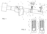
Figure 1 is a perspective view of a portion of an actuator system for a synchronizer element of a transmission of a work vehicle; -
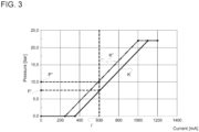
Figure 2 comprises schematic sectional views of a portion of the actuator system offigure 1 in different operational configurations; -
Figure 3 is a graph plotting pressure in function of current of actuation in a valve of the actuator system offigure 1 ; and -
Figure 4 is a schematic flowchart of a valve characterization method according to the invention. - In
figure 1 it is partially shown an actuator system 1 for asynchronizer element 2 for a transmission architecture (not shown) of a work vehicle (not shown). In particular, the transmission architecture comprises a synchronizer configured to selectively engage or disengage an element of the transmission with respect to another one. - The actuator system 1 comprise essentially a moving
shaft 3 supported in translational free manner by the vehicle along its longitudinal axis A. - The
synchronizer element 2 comprises at least aportion 4 that is fixedly carried by the movingshaft 3 and therefore moves along longitudinal axis A direction to control the engagement or disengagement of the portions ofsynchronizer element 2. - The actuator system 1 comprises actuation means 5 configured to move the moving
shaft 3 along longitudinal axis A. In particular, such actuation means 5 comprise a valve (not show into detail) that is controlled via an electric input signal. - The actuator system 1 further comprises sensor means 6 configured to detect the movement of the moving
shaft 3. In particular, the sensor means 6 comprises a magnet 7' configured to generate a magnet field and atarget 7", that is fixedly carried by movingshaft 3, configured to detect the aforementioned magnet field. - Therefore, according to a control signal provided by an electronic control unit (not shown) as defined below, actuation means 5 control the movement of moving
shaft 3. - The actuator system 1 further comprise detent means 8 configured to maintain the moving shaft in at least two predefined positions, i.e. engaged or disengaged position of the
synchronizer element 2. In particular, in the shown embodiment two predefined positions are discussed while it is clear that three predefined positions may be defined, i.e. adding a so-called "neutral" position of thesynchronizer element 2. - Detents means 8 comprises a
plunger 9 configured to engage aseat 11 carried by movingshaft 3 and in particular directly realized on the movingshaft 3. In particular, the movingshaft 3, as said, comprises at least two seats 11', 11'' realized to house theplunger 9 along a direction of an axis B that is preferably perpendicular to longitudinal axis A. - The seats 11', 11'' are longitudinally adjacent along longitudinal axis A and separated by a
shoulder 12. In particular, they have a curved shape configured to allow rotation motion of theplunger 9 as defined below in detail. - The
plunger 9 essentially comprise aspherical element 13 and elastic means 14 such as a helicoidally spring. Theelastic means 14 are configured to carry saidspherical element 13, e.g. by contact, and to exert a force on this latter in order to be always in contact with the profile of the movingshaft 3, i.e. either with one of seats 11', 11'' or withshoulder 12 during the movement between the two seats 11', 11'' . - The
plunger 9 is advantageously housed in acarcass 15 that is fixedly carried by the vehicle and defines a housing for theelastic means 14 and thespherical element 13. - Making reference to figures 2A and 2B and to graph of
figure 3 , the following quantities are defined: - x is the linear distance of the movement of the moving
shaft 3 along longitudinal axis A detected by sensor means 6; - r is the radius of the
spherical element 13; - i' is the current signal applied to actuator means 5 that generate an x movement of the moving
shaft 3; - p', p'' is the pressure exerted to the
portion 4 of thesynchronizer element 2 due to input current i'; and - k', k'' is the slope of the valve characteristic by plotting pressure values in function of applied current signal.
- In addition to the above, the aforementioned distance is the distance of the center of the radius r of the
spherical element 13 with respect to the middle axis of theseat 11', 11". - The electronic control unit may be part of the actuator system and/or of the transmission and/or of the vehicle and comprises elaboration means configured to memorize at least some of the above listed quantities and to acquire data from the aforementioned position sensor means.
- The operation of the above described actuator system 1 is the following.
- During the operation of the transmission of the work vehicle, the moving
shaft 3 is controlled by actuator means 5 to move along longitudinal axis A thereby controlling the engagement of transmission elements viaportion 4. The current signal i' is imparted to actuation means thereby allowing the passage of the movingshaft 3 so that detent means 8 maintain the latter in the at least two aforementioned positions, i.e. so that theplunger 9 is seated in one ofseats 11. The current signal i' is provided in function of the needed pressure atsynchronizer element 2 by a characterization mapping that is memorized in the electronic control unit of the transmission/vehicle. - In particular, the invention relates to a characterization method, schematized in
figure 4 , for valve means of an actuator system 1 as described above and comprising the following steps: - i) the electronic control units provides a first current value iN, wherein N is 0 at start, suitable to move moving
shaft 3 along its longitudinal axis A in order to allowplunger 9 to move towards theshoulder 12; - ii) position sensor means reads the position value xN corresponding to the applied current value iN;
- iii) if the electronic control unit verifies that position value xN is equal to zero, the index N is increased of one and the method return back to step i), otherwise
if the electronic control unit verifies that position value xN is different from zero, estimates the pressure imparted by actuation means 5; - iv) the electronic control unit store the pressure-current data and stop the characterization method.
- In particular, the first current value may be a value of 200 mA and the subsequent increase may be of 1 mA for instance each 2 ms
- Such value of subsequent increases may be modified by the user, acting on the electronic control unit, to tune the quality of the detected valve characteristic.
- The estimation of the pressure at point iv) imparted by valve means may be estimated as follows.
- Pressure exerted by hydraulic actuation means to control synchronizer element depends on the area A of the hydraulic actuation means (i.e. the piston axial area) multiplied by hydraulic force imparted by the hydraulic actuation means, that is contrasted by plunger means 9 force, i.e.

- The force exerted by the plunger means 9 depends on the vertical compression Y of
elastic means 14 along axis B multiplied by elastic means stiffness, k:
- The vertical compression Y of the elastic means 14 along axis B may be estimated in function of detected distance x and of memorized radius r:

- Such function may be memorized in the electronic control unit and clearly varies in function of the dimensions of plunger/seats i.e. of radius r.
- Therefore, in the end, the pressure may be directly linked to the control current signal provided to the magnet.

- The aforementioned method is advantageously executed by the electronic control unit at a specific condition, i.e. at any requested characterization of the actuator system 1 or at its first operation or after any maintenance.
- The aforementioned method can also be executed by the electronic control unit at any suitable predefined timing to ensure continuous correct data linked to the valve characteristic.
- The aforementioned method may further comprise the update of a characterization map memorized in the electronic control unit with the characterization current-pressure point retrieved by the aforementioned method. In other words, the starting point of the slope of the valve is updated.
- In view of the foregoing, the advantages of method for characterization of an actuator valve for a transmission of a work vehicle according to the invention are apparent.
- Making reference to
figure 3 , the above described method allows to estimate the different starting of the inclination k', k" of each valve. Indeed, as shown, different valve means in the same transmission architecture, even if equal, or the same valve mean after a long usage, may lead, via the same input current signal i' to different pressure p', p'' as output. - In particular, the above effect is reached without using any pressure sensor downstream to valve means, thereby reducing costs and encumbrance of the transmission.
- Accordingly, the above mentioned characterization method may be provided in any typology of transmission with small modifications, without increasing costs.
- Since the valve characteristic may be calibrated at each needed occurrence, the accuracy in controlling synchronizer element is increased,
- It is clear that modifications can be made to method for characterization of an actuator valve for a transmission of a work vehicle which do not extend beyond the scope of protection defined by the claims.
- For example, the plunger may be realized differently or, as said, the seats may be more than two.
- Furthermore, the function relating the compression of elastic means related to longitudinal movement of the moving shaft may be of any typology.
- Distance sensor means may be realized of any suitable typology.
- Moreover, as outlined, the timing of execution of the method and the current steps may vary according to the need of the typology of vehicle and its use.
Claims (12)
- Method for characterization of a valve for an actuator system (1) for a work vehicle,said actuator system (1) comprising a shaft (3) moving along a longitudinal axis (A) and actuator means (5) provided with a valve to move said shaft (3),said actuator system (1) comprising detent means (8) comprising a plunger (9) configured to be housed in one among a plurality of seats (11', 11'') fixedly carried by said shaft (3) and separated by a shoulder (12), said plunger (9) comprising a spherical element (13) configured to cooperate by contact with one among said plurality of seats (11', 11'') and elastic means (14) configured to exert a force to maintain said spherical element (13) in contact with said one among said plurality of seats (11', 11'')said actuator system (1) further comprising position sensor means (6) configured to detect the position of said spherical elementsaid work vehicle comprising an electronic control unit comprising elaboration means configured to memorize quantities related to said actuator system (1) and to acquire data from said position sensor means (6), said method comprising the following steps:i) the electronic control units provides a first current value iN, wherein N is 0 at start, suitable to move moving shaft (3) along its longitudinal axis A in order to allow plunger (9) to move towards the shoulder (12);ii) position sensor means reads the position value xN corresponding to the applied current value iN;iii) if the electronic control unit verifies that position value xN is equal to zero, the index N is increased of one and the method return back to step i), otherwise
if the electronic control unit verifies that position value xN is different from zero, estimates the pressure imparted by actuation means (5);iv) the electronic control unit store the pressure-current data and stop the characterization method. - Method according to claim 1, wherein he first current value is 200 mA.
- Method according to claim 1 or 2, wherein the subsequent increase of current value is of 1 mA.
- Method according to claim 3, wherein the subsequent increase is executed each 2 ms.
- Method according to claim 1 or 2, wherein the value of said subsequent increases are tunable by the user.
- Method according to any of the aforementioned claims, wherein the estimation of said pressure is obtained by the following formula
 - A is the area of a hydraulic actuator controlled by valve means;- k is the stiffness of the elastic means (14);- f(x(i), r) is a predefined function of the detected longitudinal displacement x and a radius r of said spherical element (13).the aforementioned values A, k, r, and the function f(x(i), r) being memorized in said electronic control unit.
 - Method according to any of the preceding claims, wherein the aforementioned steps are executed according to a specific condition.
- Method according to any of the preceding claims, wherein the aforementioned steps are executed according to a specific condition.
- Method according to the any of the preceding claims, further comprising the step of updating of a characterization map memorized in the electronic control unit by the current-pressure value stored in step iv).
- Electronic control unit comprising elaboration means configured to memorize and execute the method according to any of the preceding claims.
- Transmission for a work vehicle comprising an actuator system (1) for a synchronizer element of said transmission, said actuator system (1) comprising a shaft (3) moving along a longitudinal axis (A) and actuator means (5) provided with a valve to move said shaft (3),said actuator system (1) comprising detent means (8) comprising a plunger (9) configured to be housed in one among a plurality of seats (11', 11'') fixedly carried by said shaft (3) and separated by a shoulder (12), said plunger (9) comprising a spherical element (13) configured to cooperate by contact with one among said plurality of seats (11', 11'') and elastic means (14) configured to exert a force to maintain said spherical element (13) in contact with said one among said plurality of seats (11', 11"),said actuator system (1) further comprising position sensor means (6) configured to detect the position of said spherical element said work vehicle, said transmission comprising an electronic control unit comprising elaboration means configured execute the aforementioned characterization method.
- Work vehicle comprising a transmission provided with a synchronizer element (2) and an actuator system (1) for said synchronizer element (2), said actuator system (1) comprising a shaft (3) moving along a longitudinal axis (A) and carrying a portion (4) for carrying said synchronizer element (2) and actuation means (5) provided with a valve configured to move said shaft (3),said actuator system (1) comprising detent means (8) comprising a plunger (9) configured to be housed in one among a plurality of seats (11', 11'') fixedly carried by said shaft (3) and separated by a shoulder (12), said plunger (9) comprising a spherical element (13) configured to cooperate by contact with one among said plurality of seats (11', 11') and elastic means (14) configured to exert a force to maintain said spherical element (13) in contact with said one among said plurality of seats (11', 11"),said actuator system (1) further comprising position sensor means (6) configured to detect the position of said spherical element said work vehicle, said work vehicle comprising an electronic control unit comprising elaboration means configured execute the aforementioned characterization method.
Applications Claiming Priority (1)
| Application Number | Priority Date | Filing Date | Title |
|---|---|---|---|
| IT102022000018345A IT202200018345A1 (en) | 2022-09-08 | 2022-09-08 | METHOD FOR ESTIMATING THE VALVE CHARACTERISTIC OF AN ACTUATOR SYSTEM OF A WORK VEHICLE TRANSMISSION |
Publications (1)
| Publication Number | Publication Date |
|---|---|
| EP4336071A1 true EP4336071A1 (en) | 2024-03-13 |
Family
ID=87889862
Family Applications (1)
| Application Number | Title | Priority Date | Filing Date |
|---|---|---|---|
| EP23195876.0A Withdrawn EP4336071A1 (en) | 2022-09-08 | 2023-09-07 | Method for estimating a valve characteristic for an actuator system of a work vehicle transmission |
Country Status (2)
| Country | Link |
|---|---|
| EP (1) | EP4336071A1 (en) |
| IT (1) | IT202200018345A1 (en) |
Citations (2)
| Publication number | Priority date | Publication date | Assignee | Title |
|---|---|---|---|---|
| FR2849129A1 (en) * | 2002-12-19 | 2004-06-25 | Renault Sa | METHOD AND DEVICE FOR DRIVING A SYSTEM FOR ENGAGING TRANSMISSION GEARS IN A ROBOTIC MECHANICAL GEARBOX |
| EP1887258A1 (en) * | 2006-08-01 | 2008-02-13 | Peugeot Citroën Automobiles S.A. | Method of determining start and end jaw clutching positions and gearbox estimating a start and end jaw clutching position when shifting gear |
-
2022
- 2022-09-08 IT IT102022000018345A patent/IT202200018345A1/en unknown
-
2023
- 2023-09-07 EP EP23195876.0A patent/EP4336071A1/en not_active Withdrawn
Patent Citations (2)
| Publication number | Priority date | Publication date | Assignee | Title |
|---|---|---|---|---|
| FR2849129A1 (en) * | 2002-12-19 | 2004-06-25 | Renault Sa | METHOD AND DEVICE FOR DRIVING A SYSTEM FOR ENGAGING TRANSMISSION GEARS IN A ROBOTIC MECHANICAL GEARBOX |
| EP1887258A1 (en) * | 2006-08-01 | 2008-02-13 | Peugeot Citroën Automobiles S.A. | Method of determining start and end jaw clutching positions and gearbox estimating a start and end jaw clutching position when shifting gear |
Also Published As
| Publication number | Publication date |
|---|---|
| IT202200018345A1 (en) | 2024-03-08 |
Similar Documents
| Publication | Publication Date | Title |
|---|---|---|
| KR100436278B1 (en) | The gear ratio selector mechanism | |
| US20100152985A1 (en) | Method and device for controlling the degree of engagement of an automatic or automated motor vehicle clutch | |
| US6050379A (en) | Algorithm for electro-mechanical clutch actuator | |
| EP2221511B1 (en) | Fluid pressure control apparatus and process | |
| KR102651961B1 (en) | Clutch control method for vehicle | |
| CN102159836B (en) | Control device for stroke of actuator | |
| CN111963673B (en) | Self-learning method and system for half-joint point of wet-type double-clutch transmission | |
| JP2008232245A (en) | Flow control valve of clutch control device | |
| US7484429B2 (en) | Closed loop adaptive fluid control system and method | |
| GB2493380A (en) | A method of calibrating a selected gear sensor | |
| EP1411262B1 (en) | Clutch control device | |
| US6989729B2 (en) | Proportional pressure control valve for controlling the pressure level in a hydraulic circuit | |
| KR20090007299A (en) | Apparatus and method for facilitating gear shifting in mechanical gear boxes | |
| EP2989342B1 (en) | System and method for the update of fill parameters in wet clutches through cross learning | |
| US8074533B2 (en) | Servo assistance device for motor vehicle variable-speed transmission | |
| US9114790B2 (en) | Shift-by-wire actuation of a transmission park brake | |
| EP1416182B1 (en) | Clutch control device | |
| US9523377B2 (en) | Method for controlling an actuator | |
| CN109780086B (en) | Hydraulic control device and method for controlling a dual clutch transmission | |
| JP2006292007A (en) | Automatic transmission control device | |
| EP1184607B1 (en) | A control device for an actuator applied in a transmission | |
| US9316271B2 (en) | Adaptive control of a linear actuator | |
| EP1193425A2 (en) | Shift actuating control system for synchromesh-type automatic transmission | |
| WO2005108148A2 (en) | An observed-based control method for automatically shifting a manul transmission | |
| JP2009138937A (en) | Servo assist device for automobile transmission |
Legal Events
| Date | Code | Title | Description |
|---|---|---|---|
| PUAI | Public reference made under article 153(3) epc to a published international application that has entered the european phase |
Free format text: ORIGINAL CODE: 0009012 |
|
| STAA | Information on the status of an ep patent application or granted ep patent |
Free format text: STATUS: THE APPLICATION HAS BEEN PUBLISHED |
|
| AK | Designated contracting states |
Kind code of ref document: A1 Designated state(s): AL AT BE BG CH CY CZ DE DK EE ES FI FR GB GR HR HU IE IS IT LI LT LU LV MC ME MK MT NL NO PL PT RO RS SE SI SK SM TR |
|
| STAA | Information on the status of an ep patent application or granted ep patent |
Free format text: STATUS: REQUEST FOR EXAMINATION WAS MADE |
|
| 17P | Request for examination filed |
Effective date: 20240913 |
|
| RBV | Designated contracting states (corrected) |
Designated state(s): AL AT BE BG CH CY CZ DE DK EE ES FI FR GB GR HR HU IE IS IT LI LT LU LV MC ME MK MT NL NO PL PT RO RS SE SI SK SM TR |
|
| STAA | Information on the status of an ep patent application or granted ep patent |
Free format text: STATUS: THE APPLICATION IS DEEMED TO BE WITHDRAWN |
|
| 18D | Application deemed to be withdrawn |
Effective date: 20240914 |