EP4336052A1 - Variable vaneless diffuser with moving floor - Google Patents
Variable vaneless diffuser with moving floor Download PDFInfo
- Publication number
- EP4336052A1 EP4336052A1 EP23196913.0A EP23196913A EP4336052A1 EP 4336052 A1 EP4336052 A1 EP 4336052A1 EP 23196913 A EP23196913 A EP 23196913A EP 4336052 A1 EP4336052 A1 EP 4336052A1
- Authority
- EP
- European Patent Office
- Prior art keywords
- variable
- plate
- shroud
- diffuser
- floor plate
- Prior art date
- Legal status (The legal status is an assumption and is not a legal conclusion. Google has not performed a legal analysis and makes no representation as to the accuracy of the status listed.)
- Pending
Links
Images




Classifications
-
- F—MECHANICAL ENGINEERING; LIGHTING; HEATING; WEAPONS; BLASTING
- F04—POSITIVE - DISPLACEMENT MACHINES FOR LIQUIDS; PUMPS FOR LIQUIDS OR ELASTIC FLUIDS
- F04D—NON-POSITIVE-DISPLACEMENT PUMPS
- F04D29/00—Details, component parts, or accessories
- F04D29/40—Casings; Connections of working fluid
- F04D29/42—Casings; Connections of working fluid for radial or helico-centrifugal pumps
- F04D29/44—Fluid-guiding means, e.g. diffusers
- F04D29/46—Fluid-guiding means, e.g. diffusers adjustable
- F04D29/462—Fluid-guiding means, e.g. diffusers adjustable especially adapted for elastic fluid pumps
- F04D29/464—Fluid-guiding means, e.g. diffusers adjustable especially adapted for elastic fluid pumps adjusting flow cross-section, otherwise than by using adjustable stator blades
-
- F—MECHANICAL ENGINEERING; LIGHTING; HEATING; WEAPONS; BLASTING
- F05—INDEXING SCHEMES RELATING TO ENGINES OR PUMPS IN VARIOUS SUBCLASSES OF CLASSES F01-F04
- F05D—INDEXING SCHEME FOR ASPECTS RELATING TO NON-POSITIVE-DISPLACEMENT MACHINES OR ENGINES, GAS-TURBINES OR JET-PROPULSION PLANTS
- F05D2250/00—Geometry
- F05D2250/50—Inlet or outlet
- F05D2250/52—Outlet
Definitions
- the present disclosure relates generally to aircraft environmental control systems and in particular to a vaneless, low-solidity diffuser with a moving floor and variable flow area.
- Environmental control systems can provide conditioned air to an aircraft cabin.
- a cabin air compressor can be used to compress air for use in an environmental control system, and the cabin air compressor can include a variable diffuser.
- Many variable diffusers include a system of vanes which can vary the amount of airflow through the diffuser.
- vaned diffusers present a number of disadvantages. The vanes are constructed individually and then assembled, leading to high manufacturing costs and increased assembly time. Additionally, there are a large number of wear surfaces within the system due to the rotation of the vanes, which can decrease part life and increase maintenance costs.
- a variable vaneless diffuser in one aspect, includes a shroud, a backing plate, a divider plate adjacent to the backing plate, a floor plate adjacent to the shroud, a plurality of standoffs formed on the divider plate, and a plurality of clearance slots formed in the floor plate.
- the divider plate is between the shroud and the backing plate.
- the floor plate is between the shroud and the divider plate and is movable relative to the divider plate.
- the plurality of standoffs and the plurality of clearance slots define a flow path for fluid flow.
- the flow path has an area which is variable through movement of the floor plate relative to the divider plate.
- a compressor in another aspect, includes a compressor housing, an impeller, and a variable vaneless diffuser downstream from the impeller.
- the compressor housing includes an inlet, an outlet, and a duct connecting the inlet to the outlet.
- the impeller is within the duct in the compressor housing.
- the variable vaneless diffuser is within the duct and includes a shroud, a backing plate, a divider plate adjacent to the backing plate, a floor plate adjacent to the shroud, a plurality of standoffs formed on the divider plate, and a plurality of clearance slots formed in the floor plate.
- the divider plate is between the shroud and the backing plate.
- the floor plate is between the shroud and the divider plate and is movable relative to the divider plate.
- the plurality of standoffs and the plurality of clearance slots define a flow path for fluid flow.
- the flow path has an area which is variable through movement of the floor plate relative to the divider plate.
- a vaneless low-solidity diffuser can include a movable floor and a series of mating standoffs and clearance slots.
- the movable floor can be actuated to provide continuous motion over a range of flow areas.
- standoffs/clearance slots with an actuated floor allows for the elimination of individual vanes, which are costly to produce and assemble, and reduces weight and part count of the diffuser system.
- the low-solidity design (using standoffs which take up a low percentage of the surface area of the backing plate) allows for better performance across a wider range of operating conditions as compared to a channel diffuser.
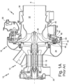
- FIG. 1A is a cross-sectional view of prior art air compressor 10.
- Prior art air compressor 10 includes motor 12, compressor section 14, prior art vaned diffuser 16, and tie rod 18. Also shown in FIG. 1A is axis X.
- Motor 12 drives compressor section 14 in prior art air compressor 10. Air will enter into compressor section 14 and then flow through prior art vaned diffuser 16 before exiting compressor section 14.
- Tie rod 18 extends through prior art air compressor 10 and is centered on axis X.
- Motor 12 and compressor section 14 are mounted to tie rod 18. Motor 12 will drive tie rod 18 and cause it to rotate, which in turn will rotate compressor section 14.
- FIG. 1B is a cross-sectional view of diffuser 16. FIGS. 1A-1B will be discussed together.
- Motor 12 includes motor housing 20, motor rotor 22, and motor stator 24.
- Motor housing 20 surrounds motor rotor 22 and motor stator 24.
- Motor 12 is an electric motor with motor rotor 22 disposed within motor stator 24.
- Motor rotor 22 is rotatable about axis X.
- Motor rotor 12 is mounted to tie rod 18 to drive rotation of tie rod 18 in prior art air compressor 10.
- Compressor section 14 includes compressor housing 30, compressor inlet 32, compressor outlet 34, and compressor rotor 36.
- Compressor housing 30 includes a duct that forms compressor inlet 32 and a duct that forms compressor outlet 34.
- Compressor inlet 32 draws air into compressor section 14.
- compressor rotor 36 Positioned in compressor housing 30 is compressor rotor 36.
- Compressor rotor 36 is driven with motor 12 and is mounted on tie rod 18 to rotate with tie rod 18 about axis X. Air that is drawn into compressor section 14 through compressor inlet 32 is compressed with compressor rotor 36. The compressor air is then routed through prior art vaned diffuser 16 before exiting compressor section 14 through compressor outlet 34.
- Prior art vaned diffuser 16 includes shroud 40, vanes 42, backing plate 44, mounting plate 46, fasteners 48, pivot pins 50, drive ring 52, drive pins 54, and diffuser actuator 56.
- Shroud 40 of prior art vaned diffuser 16 can be attached to compressor housing 30. Vanes 42 are positioned between shroud 40 and backing plate 44. Backing plate 44 is held against vanes 42 with mounting plate 46. Fasteners 48 extend through openings in mounting plate 46, backing plate 44, vanes 42, and shroud 40. Vanes 42 are positioned between shroud 40 and backing plate 44 so that there is a small clearance between vanes 42 and shroud 40 and between vanes 42 and backing plate 44.
- Pivot pins 50 extend between openings in vanes 42 and openings in shroud 40. Vanes 42 can rotate about pivot pins 50.
- Drive ring 52 is positioned adjacent shroud 40.
- Drive pins 54 extend from drive ring 52 through shroud 40 into a slot in vanes 42.
- Drive ring 52 can be rotated about axis X with diffuser actuator 56.
- drive pins 54 engaged in the slots in vanes 42 will drag vanes 42 and cause them to rotate about pivot pins 50. This movement of vanes 42 will vary the gap between adjacent vanes 42 to vary the amount of air flowing between vanes 42.
- Varying the amount of air that flows between vanes 42 allows prior art vaned diffuser 16 to be used in different settings.
- the air that is taken into prior art vaned diffuser 16 is typically at a low pressure that is unsuitable for use in the cabin. Vanes 42 can thus be positioned to compress the air flowing through prior art vaned diffuser 16 before that air is routed to an environmental control system.
- FIG. 2 is a perspective cut-away view of prior art vaned diffuser 16.
- Prior art vaned diffuser 16 includes shroud 40, vanes 42, fasteners 48, pivot pins 50, drive ring 52, and drive pins 54.
- Each vane 42 includes inlet end 60, outlet end 62, first surface 64, second surface 66, leading surface 68, trailing surface 70, first aperture 80, second aperture 82, third aperture 84, first recess 86, second recess 88, slot 90, first cavity 100, second cavity 102, a third cavity (not shown in FIG. 2 ), a fourth cavity (not shown in FIG. 2 ), first notch 110, second notch 112, a third notch (not shown in FIG. 2 ), and a fourth notch (not shown in FIG. 2 ).
- Prior art vaned diffuser 16 includes vanes 42 positioned on shroud 40.
- Fasteners 48 extend through a mounting plate (not shown in FIG. 2 ), a backing plate (not shown in FIG. 2 ), vanes 42, and shroud 40 to hold vanes 42 between the backing plate and shroud 40.
- Pivot pins 50 extend through vanes 42 and shroud 40 so that vanes 42 can pivot about pivot pins 50.
- Drive ring 52 is positioned adjacent shroud 40 and has a retaining ring that extends up to be flush with the surface of shroud 40 that abuts vanes 42.
- Drive pins 54 extend from drive ring 52 into vanes 42 to engage vanes 42.
- Drive ring 52 can be rotated, causing drive pins 54 to rotate vanes 42.
- Vanes 42 are pivotally positioned in prior art vaned diffuser 16. Each vane 42 includes inlet end 60 positioned radially inward in relation to prior art vaned diffuser 16 and outlet end 62 positioned radially outward in relation to prior art vaned diffuser 16. Each vane 42 also includes first surface 64 and second surface 66 extending from inlet end 60 to outlet end 62. First surface 64 abuts the backing plate (not shown in FIG. 2 ) and second surface 64 abuts shroud 40. Each vane 42 also includes leading surface 68 and trailing surface 70 extending from inlet end 60 to outlet end 62. Leading surface 68 faces radially inward in relation to prior art vaned diffuser 16 and trailing surface 70 faces radially outward in relation to prior art vaned diffuser 16.
- Each vane 42 includes first aperture 80 and second aperture 82 extending from first surface 64 to second surface 66.
- First aperture 80 receives one fastener 48 and second aperture 82 receives one fastener 48.
- First aperture 80 and second aperture 82 are sized so that first aperture 80 and second aperture 82 do not limit the movement of vane 42 when it pivots. There is a small clearance between vanes 42 and shroud 40 and between vanes 42 and the backing plate.
- Each vane 42 also includes third aperture 84 extending from first surface 64 to second surface 66.
- Third aperture 84 is sized to receive pivot pin 50.
- Vanes 42 pivot on pivot pins 50.
- Each vane 42 further includes first recess 86, second recess 88, and slot 90.
- First recess 86 is positioned on first surface 64 of vane 42.
- Second recess 88 is positioned on second surface 66 of vane 42.
- Second recess 88 is positioned around slot 90.
- Slot 90 extends a distance into vane 42 from second surface 66.
- Slot 90 is sized to slidably engage drive pin 54. As drive ring 52 rotates, drive pins 54 can slide through slots 90 to rotate vanes 42 about pivot pins 50.
- Each vane 42 further includes first cavity 100, second cavity 102, a third cavity, and a fourth cavity.
- First cavity 100 and second cavity 102 are positioned on first surface 64.
- the third cavity and fourth cavity are positioned on second surface 66.
- the third cavity and fourth cavity are not shown in FIG. 2 , as the third cavity is positioned below first cavity 100 on second surface 66 facing shroud 40 and the fourth cavity is positioned below second cavity 102 on second surface 66 facing shroud 40.
- Vane 42 further includes first notch 110, second notch 112, a third notch, and a fourth notch.
- First notch 110 in on first surface 64 and extends from leading surface 68 to first cavity 100.
- Second notch 112 is on first surface 64 and extends from leading surface 68 to second cavity 102.
- the third notch is on second surface 66 and extends from trailing surface 70 to the third cavity.
- the fourth notch is on second surface 66 and extends from trailing surface 70 to the fourth cavity.
- the third notch and fourth notch are not shown in FIG. 2 , as they are positioned on second surface 66 facing shroud 40.
- First cavity 100, second cavity 102, the third cavity, and the fourth cavity are included on vane 42 to load vane 42 against the backing plate (not shown in FIG. 2 ).
- First notch 110, second notch 112, the third notch, and the fourth notch are included on vane 42 to vent first cavity 100, second cavity 102, the third cavity, and the fourth cavity, respectively.
- First cavity 100, second cavity 102, the third cavity, and the fourth cavity are vented to different pressures to create the load that holds vane 42 against the backing plate.
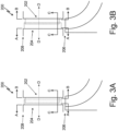
- FIG. 3A is a schematic depiction of variable vaneless diffuser 200 in a fully compressed state.
- Variable vaneless diffuser 200 includes a shroud (such as shroud 40 shown in FIGS. 1A and 2 , or shroud 216 shown in FIGS. 6A-6B ; not shown in FIGS. 3A-3B ), a backing plate (such as backing plate 44 shown in FIGS. 1A-2 ; not shown in FIGS. 3A-3B ), floor plate 202, divider plate 204, diffuser inlet section 206, and diffuser outlet section 208.
- Floor plate 202 includes standoffs 210 (shown in FIGS. 4B and 5A-5B ), and divider plate 204 includes clearance slots 212 (shown in FIGS. 4A and 5A-5B ).
- FIG. 3B is a schematic depiction of variable vaneless diffuser 200 in a fully expanded state. FIGS. 3A-3B will be discussed concurrently.
- Floor plate 202 is located adjacent to the shroud such that floor plate 202 is on a shroud side of variable vaneless diffuser 200.
- Divider plate 204 is located adjacent to the backing plate such that divider plate 204 is on a backing plate side of variable vaneless diffuser 200.
- Diffuser inlet section 206 is located radially outward of diffuser inlet section 206 with respect to an axis (such as axis X shown in FIG. 1A ).
- floor plate 202 can be slidably connected to the shroud. This slidable connection allows floor plate 202 to move along line D-D relative to divider plate 204 such that floor plate 202 can move closer to, or further from, divider plate 204.
- variable vaneless diffuser 200 can be in the fully compressed state shown in FIG. 3A when floor plate 202 is at a minimum distance from divider plate 204, and can be in the fully extended state shown in FIG. 3B when floor plate 202 is at a maximum distance from divider plate 204.
- the movement of floor plate 202 can be driven by servo pressure (which can be provided from a post-heat exchanger hose or a compressor outlet), and additionally or alternatively can be driven by an actuator (such as actuator 218 shown in FIG. 6A ).
- servo pressure which can be provided from a post-heat exchanger hose or a compressor outlet
- actuator such as actuator 218 shown in FIG. 6A
- the delivered servo pressure can reduce the load on the actuator, which can increase the life of the actuator.
- Variable vaneless diffuser 200 operates in a similar manner as prior art vaned diffuser 16 (described above in reference to FIGS. 1A-2 ).
- Variable vaneless diffuser 200 receives airflow at diffuser inlet section 206 from a compressor inlet (such as compressor inlet 32 shown in FIG. 1A ) after the airflow has passed through an impeller (such as compressor rotor 36 shown in FIG. 1A ).
- Variable vaneless diffuser 200 can thus be downstream of the impeller with respect to the direction of airflow through the compressor.
- the airflow is then diffused as it travels through variable vaneless diffuser 200 from diffuser inlet section 206 to diffuser outlet section 208 through flow path 214 (shown in FIGS. 5A-5B ).
- divider plate 204 includes standoffs 210 which each mate with a clearance slot 212 formed in floor plate 202.
- the standoffs 210 and clearance slots 212 define a flow path 214 (shown in FIGS. 5A-5B ) which has a flow area that is variable based on the movement of floor plate 202 relative to divider plate 204.
- FIG. 4A is a schematic depiction of divider plate 204 viewed along line A-A of FIGS. 3A-3B .
- Divider plate 204 includes standoffs 210.
- FIG. 4B is a schematic depiction of floor plate 202 viewed along line B-B of FIGS. 3A-3B .
- Floor plate 202 includes clearance slots 212.
- FIGS. 4A-4B will be discussed concurrently.
- floor plate 202 is located adjacent to the shroud (that is, on the shroud side of variable vaneless diffuser 200) and divider plate 204 is located adjacent to the backing plate (on the backing plate side of variable vaneless diffuser 200).
- Standoffs 210 are formed on divider plate 204 such that standoffs 210 form raised shapes which extend away from divider plate 204. In some examples, standoffs 210 can be approximate ellipses in shape.
- Clearance slots 212 are formed in floor plate 202 such that clearance slots 212 form sunken shapes which extend into floor plate 202.
- Clearance slots 212 have a shape which approximates the shape of each standoff 210 such that each standoff 210 is able to fit into a clearance slot 212.
- clearance slots 212 can be recesses which are also approximately elliptical in shape.
- the number of standoffs 210 is equal to the number of clearance slots 212 such that each standoff 210 has a corresponding clearance slot 212.
- standoffs 210 can be arranged circumferentially about floor plate 202 and be approximately evenly spaced.
- clearance slots 212 can be similarly arranged circumferentially about divider plate 204 and be approximately evenly spaced.
- floor plate 202 can be movable along line D-D (shown in FIGS. 3A-3B ) relative to divider plate 204.
- the circumference of each clearance slot 212 is slightly larger than the circumference of each standoff 210.
- this close clearance can increase the life of components within variable vaneless diffuser 200 by reducing the number of wear surfaces.
- each standoff 210 moves relative to a clearance slot 212.
- the movement of each standoff 210 with respect to the corresponding clearance slot 212 allows for the flow of air through flow path 214 to be varied as the flow area of flow path 214 changes.
- Standoffs 210 serve as flow straighteners within variable vaneless diffuser 200.
- Standoffs 210 can be integrally formed with floor plate 202, and floor plate 202 can be manufactured as a single piece through casting or additive manufacturing techniques. Similarly, clearance slots 212 can be formed in divider plate 204 through casting or additive manufacturing, machining, or a combination of these techniques.
- variable vaneless diffuser 200 in combination with the flow-straightening provided by standoffs 210, provides increased efficiency over a channel diffuser over a wider range of operating conditions.
- variable vaneless diffuser 200 may be slightly less efficient at the flow rate at which a channel diffuser achieves optimal performance, variable vaneless diffuser 200 can achieve better performance at lower and higher flow rates. This increased efficiency range is desirable for accommodating a more diverse set of operating conditions.
- FIGS. 5A-5B are schematic cross-sectional views of a section of variable vaneless diffuser 200 along line C-C of FIGS. 3A-3B .
- Shown in FIG. 5A are a mating clearance slot 212 and standoff 210, which define a portion of flow path 214, when variable vaneless diffuser 200 is in a fully compressed state.
- Shown in FIG. 5B are the mating clearance slot 212 and standoff 210 when variable vaneless diffuser 200 is in a fully expanded state.
- FIGS. 5A-5B will be discussed in turn below.
- Flow path 214 includes a flow path inlet in diffuser inlet section 206 and a flow path outlet in diffuser outlet section 208 (both shown in FIGS. 3A-3B ).
- variable vaneless diffuser 200 When variable vaneless diffuser 200 is in a fully compressed state, as in FIG. 5A , flow path 214 has a minimum flow area. When variable vaneless diffuser 200 is in a fully expanded state, as in FIG. 5A , flow path 214 has a maximum flow area. The flow area of flow path 214 can be varied based upon the pressure and speed of air which is entering variable vaneless diffuser 200.
- FIG. 6A is a schematic depiction of the shroud side of variable vaneless diffuser 200 which includes shroud 216, floor plate 202, and actuator 218.
- Shroud 216 and floor plate 202 define floor cavity 220.
- FIG. 6B is a schematic depiction of slider seal 222 which connects shroud 216 and floor plate 202.
- FIGS. 6A-6B will be discussed concurrently.
- Shroud 216 can operate in substantially the same manner as shroud 40 (described above in reference to FIGS. 1A-2 ).
- floor plate 202 is slidably connected to shroud 216 such that floor plate 202 is movable relative to divider plate 204 (shown in FIGS. 3A-3B ) along line D-D.
- Floor plate 202 can be slidably connected to shroud 216 via a sliding mechanism.
- This sliding mechanism can be, for example a seal ring such as slider seal 222.
- the sliding mechanism can additionally or alternatively be a metallic seal, a non-metallic seal, or a slipper seal.
- Servo pressure can be supplied to floor cavity 220 from a servo pressure source, such as a heat exchanger outlet or a compressor outlet (such as compressor outlet 34 shown in FIG. 1A ). Ambient pressure, in addition to the added pressure from the compressor outlet, can be less than the pressure within flow path 214. This enables the movement of floor plate 202 away from divider plate 204 by allowing the flow path area to increase.
- actuator 218 can be used to drive the movement of floor plate 202 relative to shroud 216 and divider plate 204. Actuator 218 can supplement servo pressure provided to floor cavity 220.
- actuator 218 can be a torque motor. In other examples, actuator 218 can be a linear actuator.
- FIG. 7 is a schematic depiction of air compressor 224 including variable channel diffuser 200.
- Air compressor 224 includes ram air scoop 226, compressor housing inlet 228, impeller 230, variable channel diffuser 200, and compressor housing outlet 232.
- Air compressor 224 also includes a servo pressure system with ambient pressure air duct 234, torque motor 236, compressed pressure air duct 238, and servo pressure air duct 240.
- Air scoop 226 is located along a body of an aircraft and ducts ambient air into air compressor 224.
- Air compressor 224 includes a compressor housing, and compressor housing inlet 228, impeller 230, variable diffuser 200, and compressor housing outlet 232 are all located within the compressor housing.
- Air compressor 224 operates similarly to compressor 10 (shown in FIG. 1A ).
- Compressor housing inlet 228 receives air from ram air scoop 226 and moves air toward impeller 230. Air then moves through impeller 230 where velocity increases.
- Impeller 230 is upstream from variable diffuser 200. Air moves from impeller 230 into open channels in variable channel diffuser 200. Within variable diffuser 200, air loses velocity and increases in pressure. Compressed air moves out of variable channel diffuser 200 toward compressor housing outlet 232.
- compressor 224 includes a servo pressure system to adjust the area of flow path 214 within variable channel diffuser 200 using servo pressure.
- Ambient pressure air duct 234 connects ram air scoop 226 with torque motor 236.
- Ambient pressure air duct 234 can receive ambient air from the external environment of the aircraft (i.e., through ram air scoop 226) and/or receive air from a compressor inlet.
- Compressed pressure air duct 238 connects a portion of the compressor housing downstream from variable diffuser 200 with torque motor 236. Additionally or alternatively, compressed pressure air duct 238 can use air from a heat exchanger downstream of air compressor 224.
- Servo pressure air duct 240 connects torque motor 236 to variable channel diffuser 200.
- Torque motor 236 can combine air at an ambient pressure (P AMB ) with air at a compressed pressure (Pco). Ambient pressure is dependent on the altitude of the aircraft. Compressed pressure is dependent on the area of flow path 214 within variable channel diffuser 200. Torque motor 236 can generate a flow of air at a servo pressure (P SERVO ) by, for example, mixing ambient pressure air and compressed pressure air. Servo pressure air duct 240 moves air at servo pressure (P SERVO ). Servo pressure air duct 240 can connect to a cavity (such as cavity 220 shown in FIG. 6A ).
- servo pressure When servo pressure is higher than pressure within the compressor housing between torque motor 236 and variable diffuser 200, servo pressure can drive floor plate 202 to move between various positions (for example, between the fully compressed state shown in FIG. 5A and the fully extended state shown in FIG. 5B ). Servo pressure can be used in combination with, or in place of, an actuator such as torque motor 236 to help reduce the load on the actuator, thus increasing actuator lifespan.
- variable vaneless diffuser as described herein provides numerous advantages.
- the number of wear surfaces are greatly reduced as compared to a diffuser including vanes.
- Time and costs relating to manufacturing, assembly, and maintenance can be reduced due to a lower number of parts.
- a low-solidity design provides increased efficiency over a greater range of operating conditions than a channel diffuser, and decreases the impact of flow leakage on diffuser performance.
- the use of a variable vaneless diffuser can decrease system weight as compared to conventional vaned diffusers.
Landscapes
- Engineering & Computer Science (AREA)
- Mechanical Engineering (AREA)
- General Engineering & Computer Science (AREA)
- Structures Of Non-Positive Displacement Pumps (AREA)
Abstract
Description
- The present disclosure relates generally to aircraft environmental control systems and in particular to a vaneless, low-solidity diffuser with a moving floor and variable flow area.
- Environmental control systems can provide conditioned air to an aircraft cabin. A cabin air compressor can be used to compress air for use in an environmental control system, and the cabin air compressor can include a variable diffuser. Many variable diffusers include a system of vanes which can vary the amount of airflow through the diffuser. However, vaned diffusers present a number of disadvantages. The vanes are constructed individually and then assembled, leading to high manufacturing costs and increased assembly time. Additionally, there are a large number of wear surfaces within the system due to the rotation of the vanes, which can decrease part life and increase maintenance costs.
- In one aspect, a variable vaneless diffuser includes a shroud, a backing plate, a divider plate adjacent to the backing plate, a floor plate adjacent to the shroud, a plurality of standoffs formed on the divider plate, and a plurality of clearance slots formed in the floor plate. The divider plate is between the shroud and the backing plate. The floor plate is between the shroud and the divider plate and is movable relative to the divider plate. The plurality of standoffs and the plurality of clearance slots define a flow path for fluid flow. The flow path has an area which is variable through movement of the floor plate relative to the divider plate.
- In another aspect, a compressor includes a compressor housing, an impeller, and a variable vaneless diffuser downstream from the impeller. The compressor housing includes an inlet, an outlet, and a duct connecting the inlet to the outlet. The impeller is within the duct in the compressor housing. The variable vaneless diffuser is within the duct and includes a shroud, a backing plate, a divider plate adjacent to the backing plate, a floor plate adjacent to the shroud, a plurality of standoffs formed on the divider plate, and a plurality of clearance slots formed in the floor plate. The divider plate is between the shroud and the backing plate. The floor plate is between the shroud and the divider plate and is movable relative to the divider plate. The plurality of standoffs and the plurality of clearance slots define a flow path for fluid flow. The flow path has an area which is variable through movement of the floor plate relative to the divider plate.
-
-
FIGS. 1A-1B are cross-sectional views of a prior art air compressor. -
FIG. 2 is a perspective cut-away view of a prior art variable diffuser. -
FIG. 3A is a schematic depiction of a variable vaneless diffuser in a compressed state. -
FIG. 3B is a schematic depiction of the variable vaneless diffuser ofFIG. 3A in an extended state. -
FIGS. 4A-4B are schematic depictions mating standoffs and clearance slots within the variable vaneless diffuser ofFIG. 3A . -
FIG. 5A is a schematic cross-sectional view of a mating air passage and standoff within the variable vaneless diffuser ofFIG. 3A in a compressed state. -
FIG. 5B is a schematic cross-sectional view of the mating standoff and clearance slot ofFIG. 5A in an expanded state. -
FIG. 6A is a schematic depiction of the variable vaneless diffuser ofFIG. 3A including a sliding mechanism. -
FIG. 6B is a schematic depiction of the sliding mechanism ofFIG. 6A . -
FIG. 7 is a schematic depiction of an air compressor including the variable vaneless diffuser ofFIG. 3A . - A vaneless low-solidity diffuser can include a movable floor and a series of mating standoffs and clearance slots. The movable floor can be actuated to provide continuous motion over a range of flow areas. The use of standoffs/clearance slots with an actuated floor allows for the elimination of individual vanes, which are costly to produce and assemble, and reduces weight and part count of the diffuser system. Additionally, the low-solidity design (using standoffs which take up a low percentage of the surface area of the backing plate) allows for better performance across a wider range of operating conditions as compared to a channel diffuser.
-
FIG. 1A is a cross-sectional view of priorart air compressor 10. Priorart air compressor 10 includesmotor 12,compressor section 14, prior artvaned diffuser 16, andtie rod 18. Also shown inFIG. 1A is axis X.Motor 12drives compressor section 14 in priorart air compressor 10. Air will enter intocompressor section 14 and then flow through prior art vaneddiffuser 16 before exitingcompressor section 14.Tie rod 18 extends through priorart air compressor 10 and is centered on axis X.Motor 12 andcompressor section 14 are mounted totie rod 18.Motor 12 will drivetie rod 18 and cause it to rotate, which in turn will rotatecompressor section 14.FIG. 1B is a cross-sectional view ofdiffuser 16.FIGS. 1A-1B will be discussed together. -
Motor 12 includesmotor housing 20,motor rotor 22, andmotor stator 24.Motor housing 20 surroundsmotor rotor 22 andmotor stator 24.Motor 12 is an electric motor withmotor rotor 22 disposed withinmotor stator 24.Motor rotor 22 is rotatable about axis X.Motor rotor 12 is mounted totie rod 18 to drive rotation oftie rod 18 in priorart air compressor 10. -
Compressor section 14 includescompressor housing 30,compressor inlet 32,compressor outlet 34, andcompressor rotor 36.Compressor housing 30 includes a duct that formscompressor inlet 32 and a duct that formscompressor outlet 34.Compressor inlet 32 draws air intocompressor section 14. Positioned incompressor housing 30 iscompressor rotor 36.Compressor rotor 36 is driven withmotor 12 and is mounted ontie rod 18 to rotate withtie rod 18 about axis X. Air that is drawn intocompressor section 14 throughcompressor inlet 32 is compressed withcompressor rotor 36. The compressor air is then routed through prior artvaned diffuser 16 before exitingcompressor section 14 throughcompressor outlet 34. - Prior art
vaned diffuser 16 includesshroud 40,vanes 42, backingplate 44, mountingplate 46,fasteners 48, pivot pins 50,drive ring 52, drive pins 54, anddiffuser actuator 56.Shroud 40 of prior artvaned diffuser 16 can be attached tocompressor housing 30.Vanes 42 are positioned betweenshroud 40 andbacking plate 44. Backingplate 44 is held againstvanes 42 with mountingplate 46.Fasteners 48 extend through openings in mountingplate 46, backingplate 44,vanes 42, andshroud 40.Vanes 42 are positioned betweenshroud 40 andbacking plate 44 so that there is a small clearance betweenvanes 42 andshroud 40 and betweenvanes 42 andbacking plate 44. - Pivot pins 50 extend between openings in
vanes 42 and openings inshroud 40.Vanes 42 can rotate about pivot pins 50. Drivering 52 is positionedadjacent shroud 40. Drive pins 54 extend fromdrive ring 52 throughshroud 40 into a slot invanes 42. Drivering 52 can be rotated about axis X withdiffuser actuator 56. Asdrive ring 52 is rotated, drive pins 54 engaged in the slots invanes 42 will dragvanes 42 and cause them to rotate about pivot pins 50. This movement ofvanes 42 will vary the gap betweenadjacent vanes 42 to vary the amount of air flowing betweenvanes 42. - Varying the amount of air that flows between
vanes 42 allows prior artvaned diffuser 16 to be used in different settings. First, when an aircraft is positioned on the ground the air that is taken into prior artvaned diffuser 16 is typically at a pressure that is suitable for use in the cabin.Vanes 42 can thus be positioned to allow air to flow through prior artvaned diffuser 16 without compressing the air. Alternatively, when an aircraft is in flight the air that is taken into prior artvaned diffuser 16 is typically at a low pressure that is unsuitable for use in the cabin.Vanes 42 can thus be positioned to compress the air flowing through prior artvaned diffuser 16 before that air is routed to an environmental control system. -
FIG. 2 is a perspective cut-away view of prior artvaned diffuser 16. Prior artvaned diffuser 16 includesshroud 40,vanes 42,fasteners 48, pivot pins 50,drive ring 52, and drive pins 54. Eachvane 42 includesinlet end 60,outlet end 62,first surface 64,second surface 66, leadingsurface 68, trailingsurface 70,first aperture 80,second aperture 82,third aperture 84,first recess 86,second recess 88,slot 90,first cavity 100,second cavity 102, a third cavity (not shown inFIG. 2 ), a fourth cavity (not shown inFIG. 2 ),first notch 110,second notch 112, a third notch (not shown inFIG. 2 ), and a fourth notch (not shown inFIG. 2 ). - Prior art
vaned diffuser 16 includesvanes 42 positioned onshroud 40.Fasteners 48 extend through a mounting plate (not shown inFIG. 2 ), a backing plate (not shown inFIG. 2 ),vanes 42, andshroud 40 to holdvanes 42 between the backing plate andshroud 40. Pivot pins 50 extend throughvanes 42 andshroud 40 so thatvanes 42 can pivot about pivot pins 50. Drivering 52 is positionedadjacent shroud 40 and has a retaining ring that extends up to be flush with the surface ofshroud 40 that abutsvanes 42. Drive pins 54 extend fromdrive ring 52 intovanes 42 to engagevanes 42. Drivering 52 can be rotated, causing drive pins 54 to rotatevanes 42. -
Vanes 42 are pivotally positioned in prior artvaned diffuser 16. Eachvane 42 includesinlet end 60 positioned radially inward in relation to prior artvaned diffuser 16 and outlet end 62 positioned radially outward in relation to prior artvaned diffuser 16. Eachvane 42 also includesfirst surface 64 andsecond surface 66 extending frominlet end 60 to outlet end 62.First surface 64 abuts the backing plate (not shown inFIG. 2 ) andsecond surface 64 abutsshroud 40. Eachvane 42 also includes leadingsurface 68 and trailingsurface 70 extending frominlet end 60 to outlet end 62. Leadingsurface 68 faces radially inward in relation to prior artvaned diffuser 16 and trailingsurface 70 faces radially outward in relation to prior artvaned diffuser 16. - Each
vane 42 includesfirst aperture 80 andsecond aperture 82 extending fromfirst surface 64 tosecond surface 66.First aperture 80 receives onefastener 48 andsecond aperture 82 receives onefastener 48.First aperture 80 andsecond aperture 82 are sized so thatfirst aperture 80 andsecond aperture 82 do not limit the movement ofvane 42 when it pivots. There is a small clearance betweenvanes 42 andshroud 40 and betweenvanes 42 and the backing plate. - Each
vane 42 also includesthird aperture 84 extending fromfirst surface 64 tosecond surface 66.Third aperture 84 is sized to receivepivot pin 50.Vanes 42 pivot on pivot pins 50. Eachvane 42 further includesfirst recess 86,second recess 88, andslot 90.First recess 86 is positioned onfirst surface 64 ofvane 42.Second recess 88 is positioned onsecond surface 66 ofvane 42.Second recess 88 is positioned aroundslot 90.Slot 90 extends a distance intovane 42 fromsecond surface 66.Slot 90 is sized to slidably engagedrive pin 54. Asdrive ring 52 rotates, drive pins 54 can slide throughslots 90 to rotatevanes 42 about pivot pins 50. - Each
vane 42 further includesfirst cavity 100,second cavity 102, a third cavity, and a fourth cavity.First cavity 100 andsecond cavity 102 are positioned onfirst surface 64. The third cavity and fourth cavity are positioned onsecond surface 66. The third cavity and fourth cavity are not shown inFIG. 2 , as the third cavity is positioned belowfirst cavity 100 onsecond surface 66 facingshroud 40 and the fourth cavity is positioned belowsecond cavity 102 onsecond surface 66 facingshroud 40.Vane 42 further includesfirst notch 110,second notch 112, a third notch, and a fourth notch.First notch 110 in onfirst surface 64 and extends from leadingsurface 68 tofirst cavity 100.Second notch 112 is onfirst surface 64 and extends from leadingsurface 68 tosecond cavity 102. The third notch is onsecond surface 66 and extends from trailingsurface 70 to the third cavity. The fourth notch is onsecond surface 66 and extends from trailingsurface 70 to the fourth cavity. The third notch and fourth notch are not shown inFIG. 2 , as they are positioned onsecond surface 66 facingshroud 40. -
First cavity 100,second cavity 102, the third cavity, and the fourth cavity are included onvane 42 to loadvane 42 against the backing plate (not shown inFIG. 2 ).First notch 110,second notch 112, the third notch, and the fourth notch are included onvane 42 to ventfirst cavity 100,second cavity 102, the third cavity, and the fourth cavity, respectively. This allows air that is flowing through prior artvaned diffuser 16 to flow intofirst cavity 100,second cavity 102, the third cavity, and the fourth cavity throughfirst notch 110,second notch 112, the third notch, and the fourth notch, respectively.First cavity 100,second cavity 102, the third cavity, and the fourth cavity are vented to different pressures to create the load that holdsvane 42 against the backing plate. -
FIG. 3A is a schematic depiction ofvariable vaneless diffuser 200 in a fully compressed state.Variable vaneless diffuser 200 includes a shroud (such asshroud 40 shown inFIGS. 1A and2 , orshroud 216 shown inFIGS. 6A-6B ; not shown inFIGS. 3A-3B ), a backing plate (such asbacking plate 44 shown inFIGS. 1A-2 ; not shown inFIGS. 3A-3B ),floor plate 202,divider plate 204,diffuser inlet section 206, anddiffuser outlet section 208.Floor plate 202 includes standoffs 210 (shown inFIGS. 4B and5A-5B ), anddivider plate 204 includes clearance slots 212 (shown inFIGS. 4A and5A-5B ).FIG. 3B is a schematic depiction ofvariable vaneless diffuser 200 in a fully expanded state.FIGS. 3A-3B will be discussed concurrently. -
Floor plate 202 is located adjacent to the shroud such thatfloor plate 202 is on a shroud side ofvariable vaneless diffuser 200.Divider plate 204 is located adjacent to the backing plate such thatdivider plate 204 is on a backing plate side ofvariable vaneless diffuser 200.Diffuser inlet section 206 is located radially outward ofdiffuser inlet section 206 with respect to an axis (such as axis X shown inFIG. 1A ). - As described in more detail below in reference to
FIGS. 6A-6B ,floor plate 202 can be slidably connected to the shroud. This slidable connection allowsfloor plate 202 to move along line D-D relative to dividerplate 204 such thatfloor plate 202 can move closer to, or further from,divider plate 204. For example,variable vaneless diffuser 200 can be in the fully compressed state shown inFIG. 3A whenfloor plate 202 is at a minimum distance fromdivider plate 204, and can be in the fully extended state shown inFIG. 3B whenfloor plate 202 is at a maximum distance fromdivider plate 204. The movement offloor plate 202 can be driven by servo pressure (which can be provided from a post-heat exchanger hose or a compressor outlet), and additionally or alternatively can be driven by an actuator (such asactuator 218 shown inFIG. 6A ). The delivered servo pressure can reduce the load on the actuator, which can increase the life of the actuator. -
Variable vaneless diffuser 200 operates in a similar manner as prior art vaned diffuser 16 (described above in reference toFIGS. 1A-2 ).Variable vaneless diffuser 200 receives airflow atdiffuser inlet section 206 from a compressor inlet (such ascompressor inlet 32 shown inFIG. 1A ) after the airflow has passed through an impeller (such ascompressor rotor 36 shown inFIG. 1A ).Variable vaneless diffuser 200 can thus be downstream of the impeller with respect to the direction of airflow through the compressor. The airflow is then diffused as it travels throughvariable vaneless diffuser 200 fromdiffuser inlet section 206 todiffuser outlet section 208 through flow path 214 (shown inFIGS. 5A-5B ). - As described in more detail below in reference to
FIGS. 4A-5B ,divider plate 204 includesstandoffs 210 which each mate with aclearance slot 212 formed infloor plate 202. Thestandoffs 210 andclearance slots 212 define a flow path 214 (shown inFIGS. 5A-5B ) which has a flow area that is variable based on the movement offloor plate 202 relative to dividerplate 204. -
FIG. 4A is a schematic depiction ofdivider plate 204 viewed along line A-A ofFIGS. 3A-3B .Divider plate 204 includesstandoffs 210.FIG. 4B is a schematic depiction offloor plate 202 viewed along line B-B ofFIGS. 3A-3B .Floor plate 202 includesclearance slots 212.FIGS. 4A-4B will be discussed concurrently. - As described above in reference to
FIGS. 3A-3B ,floor plate 202 is located adjacent to the shroud (that is, on the shroud side of variable vaneless diffuser 200) anddivider plate 204 is located adjacent to the backing plate (on the backing plate side of variable vaneless diffuser 200).Standoffs 210 are formed ondivider plate 204 such thatstandoffs 210 form raised shapes which extend away fromdivider plate 204. In some examples,standoffs 210 can be approximate ellipses in shape.Clearance slots 212 are formed infloor plate 202 such thatclearance slots 212 form sunken shapes which extend intofloor plate 202.Clearance slots 212 have a shape which approximates the shape of eachstandoff 210 such that eachstandoff 210 is able to fit into aclearance slot 212. In examples wherestandoffs 210 are approximately elliptical,clearance slots 212 can be recesses which are also approximately elliptical in shape. The number ofstandoffs 210 is equal to the number ofclearance slots 212 such that eachstandoff 210 has acorresponding clearance slot 212. In some examples,standoffs 210 can be arranged circumferentially aboutfloor plate 202 and be approximately evenly spaced. In some examples,clearance slots 212 can be similarly arranged circumferentially aboutdivider plate 204 and be approximately evenly spaced. - As described above in reference to
FIGS. 3A-3B ,floor plate 202 can be movable along line D-D (shown inFIGS. 3A-3B ) relative to dividerplate 204. The circumference of eachclearance slot 212 is slightly larger than the circumference of eachstandoff 210. During operation ofvariable vaneless diffuser 200, this provides a close clearance between eachstandoff 210 and eachclearance slot 212 as opposed to a tight fit. This close clearance can increase the life of components withinvariable vaneless diffuser 200 by reducing the number of wear surfaces. - As described above in reference to
FIGS. 3A-3B , the axial movement offloor plate 202 relative to dividerplate 204 causes the movement of eachstandoff 210 relative to aclearance slot 212. The movement of eachstandoff 210 with respect to thecorresponding clearance slot 212 allows for the flow of air throughflow path 214 to be varied as the flow area offlow path 214 changes.Standoffs 210 serve as flow straighteners withinvariable vaneless diffuser 200. -
Standoffs 210 can be integrally formed withfloor plate 202, andfloor plate 202 can be manufactured as a single piece through casting or additive manufacturing techniques. Similarly,clearance slots 212 can be formed individer plate 204 through casting or additive manufacturing, machining, or a combination of these techniques. - The low-solidity design of
variable vaneless diffuser 200, in combination with the flow-straightening provided bystandoffs 210, provides increased efficiency over a channel diffuser over a wider range of operating conditions. For example, whilevariable vaneless diffuser 200 may be slightly less efficient at the flow rate at which a channel diffuser achieves optimal performance,variable vaneless diffuser 200 can achieve better performance at lower and higher flow rates. This increased efficiency range is desirable for accommodating a more diverse set of operating conditions. -
FIGS. 5A-5B are schematic cross-sectional views of a section ofvariable vaneless diffuser 200 along line C-C ofFIGS. 3A-3B . Shown inFIG. 5A are amating clearance slot 212 andstandoff 210, which define a portion offlow path 214, whenvariable vaneless diffuser 200 is in a fully compressed state. Shown inFIG. 5B are themating clearance slot 212 andstandoff 210 whenvariable vaneless diffuser 200 is in a fully expanded state.FIGS. 5A-5B will be discussed in turn below. - As described above in reference to
FIGS. 4A-4B ,standoffs 210 mate withclearance slots 212 to formflow path 214, and the movement ofstandoff 210 relative toclearance slot 212 is driven by the movement offloor plate 202 relative to dividerplate 204. The flow area offlow path 214 is variable based upon the position ofstandoffs 210 relative toclearance slots 212. Flowpath 214 includes a flow path inlet indiffuser inlet section 206 and a flow path outlet in diffuser outlet section 208 (both shown inFIGS. 3A-3B ). - When
variable vaneless diffuser 200 is in a fully compressed state, as inFIG. 5A ,flow path 214 has a minimum flow area. Whenvariable vaneless diffuser 200 is in a fully expanded state, as inFIG. 5A ,flow path 214 has a maximum flow area. The flow area offlow path 214 can be varied based upon the pressure and speed of air which is enteringvariable vaneless diffuser 200. -
FIG. 6A is a schematic depiction of the shroud side ofvariable vaneless diffuser 200 which includesshroud 216,floor plate 202, andactuator 218.Shroud 216 andfloor plate 202 definefloor cavity 220.FIG. 6B is a schematic depiction ofslider seal 222 which connectsshroud 216 andfloor plate 202.FIGS. 6A-6B will be discussed concurrently. -
Shroud 216 can operate in substantially the same manner as shroud 40 (described above in reference toFIGS. 1A-2 ). As described above in reference toFIGS. 3A-3B ,floor plate 202 is slidably connected toshroud 216 such thatfloor plate 202 is movable relative to divider plate 204 (shown inFIGS. 3A-3B ) along line D-D.Floor plate 202 can be slidably connected toshroud 216 via a sliding mechanism. This sliding mechanism can be, for example a seal ring such asslider seal 222. The sliding mechanism can additionally or alternatively be a metallic seal, a non-metallic seal, or a slipper seal. - Servo pressure can be supplied to
floor cavity 220 from a servo pressure source, such as a heat exchanger outlet or a compressor outlet (such ascompressor outlet 34 shown inFIG. 1A ). Ambient pressure, in addition to the added pressure from the compressor outlet, can be less than the pressure withinflow path 214. This enables the movement offloor plate 202 away fromdivider plate 204 by allowing the flow path area to increase. In some examples,actuator 218 can be used to drive the movement offloor plate 202 relative toshroud 216 anddivider plate 204.Actuator 218 can supplement servo pressure provided tofloor cavity 220. In some examples (such as the example shown inFIG. 7 ),actuator 218 can be a torque motor. In other examples,actuator 218 can be a linear actuator. -
FIG. 7 is a schematic depiction ofair compressor 224 includingvariable channel diffuser 200.Air compressor 224 includesram air scoop 226,compressor housing inlet 228,impeller 230,variable channel diffuser 200, andcompressor housing outlet 232.Air compressor 224 also includes a servo pressure system with ambientpressure air duct 234,torque motor 236, compressedpressure air duct 238, and servopressure air duct 240. -
Ram air scoop 226 is located along a body of an aircraft and ducts ambient air intoair compressor 224.Air compressor 224 includes a compressor housing, andcompressor housing inlet 228,impeller 230,variable diffuser 200, andcompressor housing outlet 232 are all located within the compressor housing.Air compressor 224 operates similarly to compressor 10 (shown inFIG. 1A ).Compressor housing inlet 228 receives air fromram air scoop 226 and moves air towardimpeller 230. Air then moves throughimpeller 230 where velocity increases.Impeller 230 is upstream fromvariable diffuser 200. Air moves fromimpeller 230 into open channels invariable channel diffuser 200. Withinvariable diffuser 200, air loses velocity and increases in pressure. Compressed air moves out ofvariable channel diffuser 200 towardcompressor housing outlet 232. - In the example shown in
FIG. 7 ,compressor 224 includes a servo pressure system to adjust the area offlow path 214 withinvariable channel diffuser 200 using servo pressure. Ambientpressure air duct 234 connectsram air scoop 226 withtorque motor 236. Ambientpressure air duct 234 can receive ambient air from the external environment of the aircraft (i.e., through ram air scoop 226) and/or receive air from a compressor inlet. Compressedpressure air duct 238 connects a portion of the compressor housing downstream fromvariable diffuser 200 withtorque motor 236. Additionally or alternatively, compressedpressure air duct 238 can use air from a heat exchanger downstream ofair compressor 224. Servopressure air duct 240 connectstorque motor 236 tovariable channel diffuser 200.Torque motor 236 can combine air at an ambient pressure (PAMB) with air at a compressed pressure (Pco). Ambient pressure is dependent on the altitude of the aircraft. Compressed pressure is dependent on the area offlow path 214 withinvariable channel diffuser 200.Torque motor 236 can generate a flow of air at a servo pressure (PSERVO) by, for example, mixing ambient pressure air and compressed pressure air. Servopressure air duct 240 moves air at servo pressure (PSERVO). Servopressure air duct 240 can connect to a cavity (such ascavity 220 shown inFIG. 6A ). When servo pressure is higher than pressure within the compressor housing betweentorque motor 236 andvariable diffuser 200, servo pressure can drivefloor plate 202 to move between various positions (for example, between the fully compressed state shown inFIG. 5A and the fully extended state shown inFIG. 5B ). Servo pressure can be used in combination with, or in place of, an actuator such astorque motor 236 to help reduce the load on the actuator, thus increasing actuator lifespan. - A variable vaneless diffuser as described herein provides numerous advantages. The number of wear surfaces are greatly reduced as compared to a diffuser including vanes. Time and costs relating to manufacturing, assembly, and maintenance can be reduced due to a lower number of parts. A low-solidity design provides increased efficiency over a greater range of operating conditions than a channel diffuser, and decreases the impact of flow leakage on diffuser performance. Finally, the use of a variable vaneless diffuser can decrease system weight as compared to conventional vaned diffusers.
- While the invention has been described with reference to an exemplary embodiment(s), it will be understood by those skilled in the art that various changes may be made without departing from the scope of the invention as defined by the claims. In addition, many modifications may be made to adapt a particular situation or material to the teachings of the invention without departing from the scope of the claims. Therefore, it is intended that the invention not be limited to the particular embodiment(s) disclosed, but that the invention will include all embodiments falling within the scope of the appended claims.
Claims (11)
- A variable vaneless diffuser comprising:a shroud (40);a backing plate (44);a divider plate (204) adjacent to the backing plate such that the divider plate is between the shroud and the backing plate;a floor plate (202) adjacent to the shroud such that the floor plate is between the shroud and the divider plate, wherein the floor plate is movable relative to the divider plate;a plurality of standoffs (210) formed on the divider plate; anda plurality of clearance slots (212) formed in the floor plate, wherein the plurality of standoffs and the plurality of clearance slots define a flow path for fluid flow, the flow path having an area which is variable through movement of the floor plate relative to the divider plate.
- The variable vaneless diffuser of claim 1, wherein the floor plate (202) is slidably connected to the shroud (40).
- The variable vaneless diffuser of claim 2, wherein the floor plate is slidably connected to the shroud via a slider seal (222).
- The variable vaneless diffuser of claim 2, wherein the floor plate (202) has a continuous range of motion such that the area of the flow path is continuously variable between a minimum flow area and a maximum flow area.
- The variable vaneless diffuser of any preceding claim, wherein a servo pressure source provides servo pressure to move the floor plate relative to the divider plate.
- The variable vaneless diffuser of any preceding claim, further comprising an actuator (218) which drives movement of the floor plate relative to the divider plate.
- The variable vaneless diffuser of claim 6, wherein the actuator is a torque motor.
- The variable vaneless diffuser of any preceding claim, wherein each standoff (210) has an approximate elliptical shape and each clearance slot (212) has an approximate elliptical shape which mates to the approximate elliptical shape of the standoff
- The variable vaneless diffuser of any preceding claim, wherein the plurality of standoffs (210) is arranged circumferentially about the divider plate (204) and the plurality of clearance slots (212) is arranged circumferentially about the floor plate (202).
- A compressor comprising:a compressor housing (30) comprising:an inlet (228);an outlet (232); anda duct (238) connecting the inlet to the outlet;an impeller (230) within the duct in the compressor housing; anda variable vaneless diffuser (200) as claimed in any preceding claim, within the duct and downstream from the impeller.
- The compressor of claim 10, wherein the outlet of the compressor housing supplies servo pressure to move the floor plate relative to the divider plate.
Applications Claiming Priority (1)
| Application Number | Priority Date | Filing Date | Title |
|---|---|---|---|
| US17/942,942 US11873839B1 (en) | 2022-09-12 | 2022-09-12 | Variable vaneless diffuser with moving floor |
Publications (1)
| Publication Number | Publication Date |
|---|---|
| EP4336052A1 true EP4336052A1 (en) | 2024-03-13 |
Family
ID=88017610
Family Applications (1)
| Application Number | Title | Priority Date | Filing Date |
|---|---|---|---|
| EP23196913.0A Pending EP4336052A1 (en) | 2022-09-12 | 2023-09-12 | Variable vaneless diffuser with moving floor |
Country Status (2)
| Country | Link |
|---|---|
| US (1) | US11873839B1 (en) |
| EP (1) | EP4336052A1 (en) |
Citations (4)
| Publication number | Priority date | Publication date | Assignee | Title |
|---|---|---|---|---|
| US2648195A (en) * | 1945-12-28 | 1953-08-11 | Rolls Royce | Centrifugal compressor for supercharging internal-combustion engines |
| US3358965A (en) * | 1964-05-11 | 1967-12-19 | Sulzer Ag | Turbine |
| US4378194A (en) * | 1980-10-02 | 1983-03-29 | Carrier Corporation | Centrifugal compressor |
| JPH09100799A (en) * | 1995-10-06 | 1997-04-15 | Ishikawajima Harima Heavy Ind Co Ltd | Centrifugal compressor |
Family Cites Families (18)
| Publication number | Priority date | Publication date | Assignee | Title |
|---|---|---|---|---|
| NL98031C (en) * | 1957-12-23 | |||
| NL94684C (en) * | 1958-01-20 | |||
| US3826586A (en) | 1972-12-29 | 1974-07-30 | Gen Electric | Variable diffuser centrifugal pump shutter control |
| US4292807A (en) * | 1979-05-02 | 1981-10-06 | United Technologies Corporation | Variable geometry turbosupercharger system for internal combustion engine |
| US4460310A (en) * | 1982-06-28 | 1984-07-17 | Carrier Corporation | Diffuser throttle ring control |
| US4844690A (en) | 1985-01-24 | 1989-07-04 | Carrier Corporation | Diffuser vane seal for a centrifugal compressor |
| US7326027B1 (en) | 2004-05-25 | 2008-02-05 | The United States Of America As Represented By The Administrator Of The National Aeronautics And Space Administration | Devices and methods of operation thereof for providing stable flow for centrifugal compressors |
| US8696308B2 (en) | 2009-10-06 | 2014-04-15 | Cummins Ltd. | Turbomachine |
| GB2474342A (en) | 2009-10-06 | 2011-04-13 | Cummins Ltd | Turbine nozzle component connection |
| WO2011061816A1 (en) * | 2009-11-17 | 2011-05-26 | トヨタ自動車株式会社 | Centrifugal compressor and turbo supercharger |
| AU2010365829A1 (en) | 2010-12-22 | 2013-05-23 | Danfoss A/S | Variable-speed oil-free refrigerant centrifugal compressor with variable geometry diffuser |
| GB201105726D0 (en) | 2011-04-04 | 2011-05-18 | Cummins Ltd | A turbine |
| EP3171034B1 (en) * | 2012-11-09 | 2020-10-07 | Johnson Controls Technology Company | Variable geometry diffuser having extended travel |
| JP2014118925A (en) | 2012-12-19 | 2014-06-30 | Ihi Corp | Centrifugal compressor, impeller and manufacturing method of impeller |
| US9784126B2 (en) * | 2015-12-14 | 2017-10-10 | Hamilton Sundstrand Corporation | Variable-sized cooling air flow path |
| US10753370B2 (en) | 2017-05-23 | 2020-08-25 | Rolls-Royce Corporation | Variable diffuser with axially translating end wall for a centrifugal compressor |
| US11125247B2 (en) | 2018-11-16 | 2021-09-21 | Pratt & Whitney Canada Corp. | Compressor diffuser with plasma actuators |
| CN109356886A (en) | 2018-12-17 | 2019-02-19 | 珠海格力电器股份有限公司 | Centrifugal compressor and diffuser device |
-
2022
- 2022-09-12 US US17/942,942 patent/US11873839B1/en active Active
-
2023
- 2023-09-12 EP EP23196913.0A patent/EP4336052A1/en active Pending
Patent Citations (4)
| Publication number | Priority date | Publication date | Assignee | Title |
|---|---|---|---|---|
| US2648195A (en) * | 1945-12-28 | 1953-08-11 | Rolls Royce | Centrifugal compressor for supercharging internal-combustion engines |
| US3358965A (en) * | 1964-05-11 | 1967-12-19 | Sulzer Ag | Turbine |
| US4378194A (en) * | 1980-10-02 | 1983-03-29 | Carrier Corporation | Centrifugal compressor |
| JPH09100799A (en) * | 1995-10-06 | 1997-04-15 | Ishikawajima Harima Heavy Ind Co Ltd | Centrifugal compressor |
Also Published As
| Publication number | Publication date |
|---|---|
| US11873839B1 (en) | 2024-01-16 |
Similar Documents
| Publication | Publication Date | Title |
|---|---|---|
| US8147186B2 (en) | Centrifugal compressor | |
| US4844690A (en) | Diffuser vane seal for a centrifugal compressor | |
| EP2024645B1 (en) | Geared inlet guide vane for a centrifugal compressor | |
| US5784894A (en) | Integral bypass valves and air cycle machine | |
| US8221059B2 (en) | Variable geometry turbine | |
| US6945748B2 (en) | Centrifugal compressor with channel ring defined inlet recirculation channel | |
| EP1413763A1 (en) | Rotating vane diffuser for a centrifugal compressor | |
| US20160230650A1 (en) | Passive and semi-passive inlet-adjustment mechanisms for compressor, and turbocharger having same | |
| CA2963498A1 (en) | Turbine engine airfoil bleed pumping | |
| CN106232941B (en) | Controlling cooling flow in cooled turbine vanes or blades using impingement tubes | |
| CN116044816A (en) | An axially movable adjustable slotted vane diffuser and its centrifugal compressor | |
| US11873839B1 (en) | Variable vaneless diffuser with moving floor | |
| CN109026167B (en) | Turbomachine including cooling and turbine clearance control system and air supply scoop therefor | |
| EP4336051A1 (en) | Variable channel diffuser with moving floor | |
| US4321008A (en) | Wide range compressor | |
| EP2500581B1 (en) | Variable throat device for air compressor | |
| US11773870B1 (en) | Variable channel diffuser | |
| US11578612B2 (en) | Distributor for a turbomachine radial turbine, turbomachine comprising such a distributor and air conditioning system comprising such a turbomachine | |
| EP4336050A1 (en) | Variable pipe diffuser | |
| US9784376B2 (en) | Check valve assembly | |
| EP4545798B1 (en) | Guide vane assembly | |
| CN108626141B (en) | Compressor | |
| CN220551288U (en) | Impeller of centrifugal fan, centrifugal fan and range hood | |
| JPH0447199A (en) | Centrifugal compressor | |
| CN110940078A (en) | Air duct component and air conditioner with same |
Legal Events
| Date | Code | Title | Description |
|---|---|---|---|
| PUAI | Public reference made under article 153(3) epc to a published international application that has entered the european phase |
Free format text: ORIGINAL CODE: 0009012 |
|
| STAA | Information on the status of an ep patent application or granted ep patent |
Free format text: STATUS: THE APPLICATION HAS BEEN PUBLISHED |
|
| AK | Designated contracting states |
Kind code of ref document: A1 Designated state(s): AL AT BE BG CH CY CZ DE DK EE ES FI FR GB GR HR HU IE IS IT LI LT LU LV MC ME MK MT NL NO PL PT RO RS SE SI SK SM TR |
|
| STAA | Information on the status of an ep patent application or granted ep patent |
Free format text: STATUS: REQUEST FOR EXAMINATION WAS MADE |
|
| 17P | Request for examination filed |
Effective date: 20240912 |
|
| RBV | Designated contracting states (corrected) |
Designated state(s): AL AT BE BG CH CY CZ DE DK EE ES FI FR GB GR HR HU IE IS IT LI LT LU LV MC ME MK MT NL NO PL PT RO RS SE SI SK SM TR |
|
| STAA | Information on the status of an ep patent application or granted ep patent |
Free format text: STATUS: EXAMINATION IS IN PROGRESS |
|
| 17Q | First examination report despatched |
Effective date: 20260220 |