EP4336037A2 - Engine, control device, and control program - Google Patents
Engine, control device, and control program Download PDFInfo
- Publication number
- EP4336037A2 EP4336037A2 EP23189746.3A EP23189746A EP4336037A2 EP 4336037 A2 EP4336037 A2 EP 4336037A2 EP 23189746 A EP23189746 A EP 23189746A EP 4336037 A2 EP4336037 A2 EP 4336037A2
- Authority
- EP
- European Patent Office
- Prior art keywords
- temperature
- gas
- cylinder
- gas mixture
- engine
- Prior art date
- Legal status (The legal status is an assumption and is not a legal conclusion. Google has not performed a legal analysis and makes no representation as to the accuracy of the status listed.)
- Pending
Links
Images






Classifications
-
- F—MECHANICAL ENGINEERING; LIGHTING; HEATING; WEAPONS; BLASTING
- F02—COMBUSTION ENGINES; HOT-GAS OR COMBUSTION-PRODUCT ENGINE PLANTS
- F02D—CONTROLLING COMBUSTION ENGINES
- F02D19/00—Controlling engines characterised by their use of non-liquid fuels, pluralities of fuels, or non-fuel substances added to the combustible mixtures
- F02D19/06—Controlling engines characterised by their use of non-liquid fuels, pluralities of fuels, or non-fuel substances added to the combustible mixtures peculiar to engines working with pluralities of fuels, e.g. alternatively with light and heavy fuel oil, other than engines indifferent to the fuel consumed
- F02D19/08—Controlling engines characterised by their use of non-liquid fuels, pluralities of fuels, or non-fuel substances added to the combustible mixtures peculiar to engines working with pluralities of fuels, e.g. alternatively with light and heavy fuel oil, other than engines indifferent to the fuel consumed simultaneously using pluralities of fuels
- F02D19/081—Adjusting the fuel composition or mixing ratio; Transitioning from one fuel to the other
-
- F—MECHANICAL ENGINEERING; LIGHTING; HEATING; WEAPONS; BLASTING
- F02—COMBUSTION ENGINES; HOT-GAS OR COMBUSTION-PRODUCT ENGINE PLANTS
- F02P—IGNITION, OTHER THAN COMPRESSION IGNITION, FOR INTERNAL-COMBUSTION ENGINES; TESTING OF IGNITION TIMING IN COMPRESSION-IGNITION ENGINES
- F02P5/00—Advancing or retarding ignition; Control therefor
- F02P5/04—Advancing or retarding ignition; Control therefor automatically, as a function of the working conditions of the engine or vehicle or of the atmospheric conditions
- F02P5/145—Advancing or retarding ignition; Control therefor automatically, as a function of the working conditions of the engine or vehicle or of the atmospheric conditions using electrical means
- F02P5/15—Digital data processing
- F02P5/1502—Digital data processing using one central computing unit
-
- F—MECHANICAL ENGINEERING; LIGHTING; HEATING; WEAPONS; BLASTING
- F02—COMBUSTION ENGINES; HOT-GAS OR COMBUSTION-PRODUCT ENGINE PLANTS
- F02D—CONTROLLING COMBUSTION ENGINES
- F02D19/00—Controlling engines characterised by their use of non-liquid fuels, pluralities of fuels, or non-fuel substances added to the combustible mixtures
- F02D19/02—Controlling engines characterised by their use of non-liquid fuels, pluralities of fuels, or non-fuel substances added to the combustible mixtures peculiar to engines working with gaseous fuels
- F02D19/021—Control of components of the fuel supply system
- F02D19/023—Control of components of the fuel supply system to adjust the fuel mass or volume flow
-
- F—MECHANICAL ENGINEERING; LIGHTING; HEATING; WEAPONS; BLASTING
- F02—COMBUSTION ENGINES; HOT-GAS OR COMBUSTION-PRODUCT ENGINE PLANTS
- F02D—CONTROLLING COMBUSTION ENGINES
- F02D19/00—Controlling engines characterised by their use of non-liquid fuels, pluralities of fuels, or non-fuel substances added to the combustible mixtures
- F02D19/02—Controlling engines characterised by their use of non-liquid fuels, pluralities of fuels, or non-fuel substances added to the combustible mixtures peculiar to engines working with gaseous fuels
- F02D19/021—Control of components of the fuel supply system
- F02D19/023—Control of components of the fuel supply system to adjust the fuel mass or volume flow
- F02D19/024—Control of components of the fuel supply system to adjust the fuel mass or volume flow by controlling fuel injectors
-
- F—MECHANICAL ENGINEERING; LIGHTING; HEATING; WEAPONS; BLASTING
- F02—COMBUSTION ENGINES; HOT-GAS OR COMBUSTION-PRODUCT ENGINE PLANTS
- F02D—CONTROLLING COMBUSTION ENGINES
- F02D19/00—Controlling engines characterised by their use of non-liquid fuels, pluralities of fuels, or non-fuel substances added to the combustible mixtures
- F02D19/02—Controlling engines characterised by their use of non-liquid fuels, pluralities of fuels, or non-fuel substances added to the combustible mixtures peculiar to engines working with gaseous fuels
- F02D19/025—Failure diagnosis or prevention; Safety measures; Testing
-
- F—MECHANICAL ENGINEERING; LIGHTING; HEATING; WEAPONS; BLASTING
- F02—COMBUSTION ENGINES; HOT-GAS OR COMBUSTION-PRODUCT ENGINE PLANTS
- F02D—CONTROLLING COMBUSTION ENGINES
- F02D35/00—Controlling engines, dependent on conditions exterior or interior to engines, not otherwise provided for
- F02D35/02—Controlling engines, dependent on conditions exterior or interior to engines, not otherwise provided for on interior conditions
- F02D35/023—Controlling engines, dependent on conditions exterior or interior to engines, not otherwise provided for on interior conditions by determining the cylinder pressure
-
- F—MECHANICAL ENGINEERING; LIGHTING; HEATING; WEAPONS; BLASTING
- F02—COMBUSTION ENGINES; HOT-GAS OR COMBUSTION-PRODUCT ENGINE PLANTS
- F02D—CONTROLLING COMBUSTION ENGINES
- F02D35/00—Controlling engines, dependent on conditions exterior or interior to engines, not otherwise provided for
- F02D35/02—Controlling engines, dependent on conditions exterior or interior to engines, not otherwise provided for on interior conditions
- F02D35/023—Controlling engines, dependent on conditions exterior or interior to engines, not otherwise provided for on interior conditions by determining the cylinder pressure
- F02D35/024—Controlling engines, dependent on conditions exterior or interior to engines, not otherwise provided for on interior conditions by determining the cylinder pressure using an estimation
-
- F—MECHANICAL ENGINEERING; LIGHTING; HEATING; WEAPONS; BLASTING
- F02—COMBUSTION ENGINES; HOT-GAS OR COMBUSTION-PRODUCT ENGINE PLANTS
- F02D—CONTROLLING COMBUSTION ENGINES
- F02D35/00—Controlling engines, dependent on conditions exterior or interior to engines, not otherwise provided for
- F02D35/02—Controlling engines, dependent on conditions exterior or interior to engines, not otherwise provided for on interior conditions
- F02D35/025—Controlling engines, dependent on conditions exterior or interior to engines, not otherwise provided for on interior conditions by determining temperatures inside the cylinder, e.g. combustion temperatures
-
- F—MECHANICAL ENGINEERING; LIGHTING; HEATING; WEAPONS; BLASTING
- F02—COMBUSTION ENGINES; HOT-GAS OR COMBUSTION-PRODUCT ENGINE PLANTS
- F02D—CONTROLLING COMBUSTION ENGINES
- F02D35/00—Controlling engines, dependent on conditions exterior or interior to engines, not otherwise provided for
- F02D35/02—Controlling engines, dependent on conditions exterior or interior to engines, not otherwise provided for on interior conditions
- F02D35/025—Controlling engines, dependent on conditions exterior or interior to engines, not otherwise provided for on interior conditions by determining temperatures inside the cylinder, e.g. combustion temperatures
- F02D35/026—Controlling engines, dependent on conditions exterior or interior to engines, not otherwise provided for on interior conditions by determining temperatures inside the cylinder, e.g. combustion temperatures using an estimation
-
- F—MECHANICAL ENGINEERING; LIGHTING; HEATING; WEAPONS; BLASTING
- F02—COMBUSTION ENGINES; HOT-GAS OR COMBUSTION-PRODUCT ENGINE PLANTS
- F02D—CONTROLLING COMBUSTION ENGINES
- F02D41/00—Electrical control of supply of combustible mixture or its constituents
- F02D41/0025—Controlling engines characterised by use of non-liquid fuels, pluralities of fuels, or non-fuel substances added to the combustible mixtures
- F02D41/0027—Controlling engines characterised by use of non-liquid fuels, pluralities of fuels, or non-fuel substances added to the combustible mixtures the fuel being gaseous
-
- F—MECHANICAL ENGINEERING; LIGHTING; HEATING; WEAPONS; BLASTING
- F02—COMBUSTION ENGINES; HOT-GAS OR COMBUSTION-PRODUCT ENGINE PLANTS
- F02D—CONTROLLING COMBUSTION ENGINES
- F02D41/00—Electrical control of supply of combustible mixture or its constituents
- F02D41/02—Circuit arrangements for generating control signals
- F02D41/14—Introducing closed-loop corrections
- F02D41/1401—Introducing closed-loop corrections characterised by the control or regulation method
-
- F—MECHANICAL ENGINEERING; LIGHTING; HEATING; WEAPONS; BLASTING
- F02—COMBUSTION ENGINES; HOT-GAS OR COMBUSTION-PRODUCT ENGINE PLANTS
- F02D—CONTROLLING COMBUSTION ENGINES
- F02D41/00—Electrical control of supply of combustible mixture or its constituents
- F02D41/02—Circuit arrangements for generating control signals
- F02D41/14—Introducing closed-loop corrections
- F02D41/1438—Introducing closed-loop corrections using means for determining characteristics of the combustion gases; Sensors therefor
- F02D41/1444—Introducing closed-loop corrections using means for determining characteristics of the combustion gases; Sensors therefor characterised by the characteristics of the combustion gases
-
- F—MECHANICAL ENGINEERING; LIGHTING; HEATING; WEAPONS; BLASTING
- F02—COMBUSTION ENGINES; HOT-GAS OR COMBUSTION-PRODUCT ENGINE PLANTS
- F02D—CONTROLLING COMBUSTION ENGINES
- F02D41/00—Electrical control of supply of combustible mixture or its constituents
- F02D41/02—Circuit arrangements for generating control signals
- F02D41/14—Introducing closed-loop corrections
- F02D41/1438—Introducing closed-loop corrections using means for determining characteristics of the combustion gases; Sensors therefor
- F02D41/1493—Details
- F02D41/1495—Detection of abnormalities in the air/fuel ratio feedback system
-
- F—MECHANICAL ENGINEERING; LIGHTING; HEATING; WEAPONS; BLASTING
- F02—COMBUSTION ENGINES; HOT-GAS OR COMBUSTION-PRODUCT ENGINE PLANTS
- F02D—CONTROLLING COMBUSTION ENGINES
- F02D41/00—Electrical control of supply of combustible mixture or its constituents
- F02D41/22—Safety or indicating devices for abnormal conditions
-
- F—MECHANICAL ENGINEERING; LIGHTING; HEATING; WEAPONS; BLASTING
- F02—COMBUSTION ENGINES; HOT-GAS OR COMBUSTION-PRODUCT ENGINE PLANTS
- F02M—SUPPLYING COMBUSTION ENGINES IN GENERAL WITH COMBUSTIBLE MIXTURES OR CONSTITUENTS THEREOF
- F02M21/00—Apparatus for supplying engines with non-liquid fuels, e.g. gaseous fuels stored in liquid form
- F02M21/02—Apparatus for supplying engines with non-liquid fuels, e.g. gaseous fuels stored in liquid form for gaseous fuels
- F02M21/0203—Apparatus for supplying engines with non-liquid fuels, e.g. gaseous fuels stored in liquid form for gaseous fuels characterised by the type of gaseous fuel
- F02M21/0206—Non-hydrocarbon fuels, e.g. hydrogen, ammonia or carbon monoxide
-
- F—MECHANICAL ENGINEERING; LIGHTING; HEATING; WEAPONS; BLASTING
- F02—COMBUSTION ENGINES; HOT-GAS OR COMBUSTION-PRODUCT ENGINE PLANTS
- F02M—SUPPLYING COMBUSTION ENGINES IN GENERAL WITH COMBUSTIBLE MIXTURES OR CONSTITUENTS THEREOF
- F02M21/00—Apparatus for supplying engines with non-liquid fuels, e.g. gaseous fuels stored in liquid form
- F02M21/02—Apparatus for supplying engines with non-liquid fuels, e.g. gaseous fuels stored in liquid form for gaseous fuels
- F02M21/0218—Details on the gaseous fuel supply system, e.g. tanks, valves, pipes, pumps, rails, injectors or mixers
- F02M21/0248—Injectors
- F02M21/0278—Port fuel injectors for single or multipoint injection into the air intake system
-
- F—MECHANICAL ENGINEERING; LIGHTING; HEATING; WEAPONS; BLASTING
- F02—COMBUSTION ENGINES; HOT-GAS OR COMBUSTION-PRODUCT ENGINE PLANTS
- F02P—IGNITION, OTHER THAN COMPRESSION IGNITION, FOR INTERNAL-COMBUSTION ENGINES; TESTING OF IGNITION TIMING IN COMPRESSION-IGNITION ENGINES
- F02P5/00—Advancing or retarding ignition; Control therefor
- F02P5/04—Advancing or retarding ignition; Control therefor automatically, as a function of the working conditions of the engine or vehicle or of the atmospheric conditions
- F02P5/045—Advancing or retarding ignition; Control therefor automatically, as a function of the working conditions of the engine or vehicle or of the atmospheric conditions combined with electronic control of other engine functions, e.g. fuel injection
-
- F—MECHANICAL ENGINEERING; LIGHTING; HEATING; WEAPONS; BLASTING
- F02—COMBUSTION ENGINES; HOT-GAS OR COMBUSTION-PRODUCT ENGINE PLANTS
- F02D—CONTROLLING COMBUSTION ENGINES
- F02D19/00—Controlling engines characterised by their use of non-liquid fuels, pluralities of fuels, or non-fuel substances added to the combustible mixtures
- F02D19/06—Controlling engines characterised by their use of non-liquid fuels, pluralities of fuels, or non-fuel substances added to the combustible mixtures peculiar to engines working with pluralities of fuels, e.g. alternatively with light and heavy fuel oil, other than engines indifferent to the fuel consumed
- F02D19/0639—Controlling engines characterised by their use of non-liquid fuels, pluralities of fuels, or non-fuel substances added to the combustible mixtures peculiar to engines working with pluralities of fuels, e.g. alternatively with light and heavy fuel oil, other than engines indifferent to the fuel consumed characterised by the type of fuels
- F02D19/0642—Controlling engines characterised by their use of non-liquid fuels, pluralities of fuels, or non-fuel substances added to the combustible mixtures peculiar to engines working with pluralities of fuels, e.g. alternatively with light and heavy fuel oil, other than engines indifferent to the fuel consumed characterised by the type of fuels at least one fuel being gaseous, the other fuels being gaseous or liquid at standard conditions
- F02D19/0644—Controlling engines characterised by their use of non-liquid fuels, pluralities of fuels, or non-fuel substances added to the combustible mixtures peculiar to engines working with pluralities of fuels, e.g. alternatively with light and heavy fuel oil, other than engines indifferent to the fuel consumed characterised by the type of fuels at least one fuel being gaseous, the other fuels being gaseous or liquid at standard conditions the gaseous fuel being hydrogen, ammonia or carbon monoxide
-
- F—MECHANICAL ENGINEERING; LIGHTING; HEATING; WEAPONS; BLASTING
- F02—COMBUSTION ENGINES; HOT-GAS OR COMBUSTION-PRODUCT ENGINE PLANTS
- F02D—CONTROLLING COMBUSTION ENGINES
- F02D19/00—Controlling engines characterised by their use of non-liquid fuels, pluralities of fuels, or non-fuel substances added to the combustible mixtures
- F02D19/06—Controlling engines characterised by their use of non-liquid fuels, pluralities of fuels, or non-fuel substances added to the combustible mixtures peculiar to engines working with pluralities of fuels, e.g. alternatively with light and heavy fuel oil, other than engines indifferent to the fuel consumed
- F02D19/08—Controlling engines characterised by their use of non-liquid fuels, pluralities of fuels, or non-fuel substances added to the combustible mixtures peculiar to engines working with pluralities of fuels, e.g. alternatively with light and heavy fuel oil, other than engines indifferent to the fuel consumed simultaneously using pluralities of fuels
- F02D19/10—Controlling engines characterised by their use of non-liquid fuels, pluralities of fuels, or non-fuel substances added to the combustible mixtures peculiar to engines working with pluralities of fuels, e.g. alternatively with light and heavy fuel oil, other than engines indifferent to the fuel consumed simultaneously using pluralities of fuels peculiar to compression-ignition engines in which the main fuel is gaseous
-
- F—MECHANICAL ENGINEERING; LIGHTING; HEATING; WEAPONS; BLASTING
- F02—COMBUSTION ENGINES; HOT-GAS OR COMBUSTION-PRODUCT ENGINE PLANTS
- F02D—CONTROLLING COMBUSTION ENGINES
- F02D2200/00—Input parameters for engine control
- F02D2200/02—Input parameters for engine control the parameters being related to the engine
- F02D2200/04—Engine intake system parameters
- F02D2200/0406—Intake manifold pressure
-
- F—MECHANICAL ENGINEERING; LIGHTING; HEATING; WEAPONS; BLASTING
- F02—COMBUSTION ENGINES; HOT-GAS OR COMBUSTION-PRODUCT ENGINE PLANTS
- F02D—CONTROLLING COMBUSTION ENGINES
- F02D2200/00—Input parameters for engine control
- F02D2200/02—Input parameters for engine control the parameters being related to the engine
- F02D2200/04—Engine intake system parameters
- F02D2200/0414—Air temperature
-
- F—MECHANICAL ENGINEERING; LIGHTING; HEATING; WEAPONS; BLASTING
- F02—COMBUSTION ENGINES; HOT-GAS OR COMBUSTION-PRODUCT ENGINE PLANTS
- F02D—CONTROLLING COMBUSTION ENGINES
- F02D2200/00—Input parameters for engine control
- F02D2200/02—Input parameters for engine control the parameters being related to the engine
- F02D2200/06—Fuel or fuel supply system parameters
- F02D2200/0602—Fuel pressure
-
- F—MECHANICAL ENGINEERING; LIGHTING; HEATING; WEAPONS; BLASTING
- F02—COMBUSTION ENGINES; HOT-GAS OR COMBUSTION-PRODUCT ENGINE PLANTS
- F02D—CONTROLLING COMBUSTION ENGINES
- F02D2200/00—Input parameters for engine control
- F02D2200/02—Input parameters for engine control the parameters being related to the engine
- F02D2200/06—Fuel or fuel supply system parameters
- F02D2200/0606—Fuel temperature
-
- F—MECHANICAL ENGINEERING; LIGHTING; HEATING; WEAPONS; BLASTING
- F02—COMBUSTION ENGINES; HOT-GAS OR COMBUSTION-PRODUCT ENGINE PLANTS
- F02D—CONTROLLING COMBUSTION ENGINES
- F02D2200/00—Input parameters for engine control
- F02D2200/02—Input parameters for engine control the parameters being related to the engine
- F02D2200/06—Fuel or fuel supply system parameters
- F02D2200/0611—Fuel type, fuel composition or fuel quality
- F02D2200/0612—Fuel type, fuel composition or fuel quality determined by estimation
-
- F—MECHANICAL ENGINEERING; LIGHTING; HEATING; WEAPONS; BLASTING
- F02—COMBUSTION ENGINES; HOT-GAS OR COMBUSTION-PRODUCT ENGINE PLANTS
- F02D—CONTROLLING COMBUSTION ENGINES
- F02D2200/00—Input parameters for engine control
- F02D2200/02—Input parameters for engine control the parameters being related to the engine
- F02D2200/10—Parameters related to the engine output, e.g. engine torque or engine speed
- F02D2200/101—Engine speed
-
- F—MECHANICAL ENGINEERING; LIGHTING; HEATING; WEAPONS; BLASTING
- F02—COMBUSTION ENGINES; HOT-GAS OR COMBUSTION-PRODUCT ENGINE PLANTS
- F02D—CONTROLLING COMBUSTION ENGINES
- F02D41/00—Electrical control of supply of combustible mixture or its constituents
- F02D41/0002—Controlling intake air
- F02D41/0007—Controlling intake air for control of turbo-charged or super-charged engines
-
- F—MECHANICAL ENGINEERING; LIGHTING; HEATING; WEAPONS; BLASTING
- F02—COMBUSTION ENGINES; HOT-GAS OR COMBUSTION-PRODUCT ENGINE PLANTS
- F02D—CONTROLLING COMBUSTION ENGINES
- F02D41/00—Electrical control of supply of combustible mixture or its constituents
- F02D41/0025—Controlling engines characterised by use of non-liquid fuels, pluralities of fuels, or non-fuel substances added to the combustible mixtures
-
- F—MECHANICAL ENGINEERING; LIGHTING; HEATING; WEAPONS; BLASTING
- F02—COMBUSTION ENGINES; HOT-GAS OR COMBUSTION-PRODUCT ENGINE PLANTS
- F02D—CONTROLLING COMBUSTION ENGINES
- F02D41/00—Electrical control of supply of combustible mixture or its constituents
- F02D41/02—Circuit arrangements for generating control signals
- F02D41/14—Introducing closed-loop corrections
- F02D41/1438—Introducing closed-loop corrections using means for determining characteristics of the combustion gases; Sensors therefor
- F02D41/1444—Introducing closed-loop corrections using means for determining characteristics of the combustion gases; Sensors therefor characterised by the characteristics of the combustion gases
- F02D41/1446—Introducing closed-loop corrections using means for determining characteristics of the combustion gases; Sensors therefor characterised by the characteristics of the combustion gases the characteristics being exhaust temperatures
-
- F—MECHANICAL ENGINEERING; LIGHTING; HEATING; WEAPONS; BLASTING
- F02—COMBUSTION ENGINES; HOT-GAS OR COMBUSTION-PRODUCT ENGINE PLANTS
- F02D—CONTROLLING COMBUSTION ENGINES
- F02D41/00—Electrical control of supply of combustible mixture or its constituents
- F02D41/02—Circuit arrangements for generating control signals
- F02D41/14—Introducing closed-loop corrections
- F02D41/1438—Introducing closed-loop corrections using means for determining characteristics of the combustion gases; Sensors therefor
- F02D41/1444—Introducing closed-loop corrections using means for determining characteristics of the combustion gases; Sensors therefor characterised by the characteristics of the combustion gases
- F02D41/1448—Introducing closed-loop corrections using means for determining characteristics of the combustion gases; Sensors therefor characterised by the characteristics of the combustion gases the characteristics being an exhaust gas pressure
-
- Y—GENERAL TAGGING OF NEW TECHNOLOGICAL DEVELOPMENTS; GENERAL TAGGING OF CROSS-SECTIONAL TECHNOLOGIES SPANNING OVER SEVERAL SECTIONS OF THE IPC; TECHNICAL SUBJECTS COVERED BY FORMER USPC CROSS-REFERENCE ART COLLECTIONS [XRACs] AND DIGESTS
- Y02—TECHNOLOGIES OR APPLICATIONS FOR MITIGATION OR ADAPTATION AGAINST CLIMATE CHANGE
- Y02T—CLIMATE CHANGE MITIGATION TECHNOLOGIES RELATED TO TRANSPORTATION
- Y02T10/00—Road transport of goods or passengers
- Y02T10/10—Internal combustion engine [ICE] based vehicles
- Y02T10/30—Use of alternative fuels, e.g. biofuels
Definitions
- the present invention relates to an engine, a control device, and a control program.
- Patent Document 1 discloses a technique of detecting occurrence of abnormal combustion by measuring a pressure in a cylinder of an engine.
- Patent Document 2 discloses a technique of controlling an engine to be driven in a state in which the temperature of a cylinder wall surface is in a temperature range in which abnormal combustion is less likely to occur.
- Patent Document 1 Since the technique described in Patent Document 1 detects occurrence of the abnormal combustion, it is difficult to reduce occurrence of the abnormal combustion before the abnormal combustion starts.
- the technique described in Patent Document 2 drives the engine in the temperature range in which the abnormal combustion is less likely to occur, and does not reduce occurrence of the abnormal combustion before the abnormal combustion starts.
- an object of the present disclosure is to estimate occurrence of abnormal combustion before the abnormal combustion starts.
- An engine (1000) includes a cylinder (110), a piston (120), an ignition device (140), a rotation sensor (170-1), an intake temperature sensor (170-3), an intake pressure sensor (170-2), and a control device (500).
- the cylinder (110) combusts a gas mixture containing hydrogen inside.
- the piston (120) reciprocates in the cylinder (110).
- the ignition device (140) ignites the gas mixture.
- the rotation sensor (170-1) measures the rotation speed of a crankshaft (130).
- the intake temperature sensor (170-3) measures the temperature of the gas mixture.
- the intake pressure sensor (170-2) measures a first pressure value of the gas mixture.
- the control device (500) controls the hydrogen equivalent ratio of hydrogen contained in the gas mixture and/or timing of igniting the gas mixture based on the rotation speed, the temperature of the gas mixture, and the first pressure value of the gas mixture.
- a control device (500) includes an abnormal combustion estimation unit (550) and a control unit (560).
- the abnormal combustion estimation unit (550) estimates abnormal combustion in a cylinder (110) included in an engine (1000) based on the compression pressure of gas in the cylinder (110), the compression temperature of gas in the cylinder (110), the hydrogen equivalent ratio of gas in the cylinder (110), and the rotation speed of the engine (1000).
- the control unit (560) generates a first control signal for controlling the hydrogen equivalent ratio and/or timing of igniting gas in the cylinder (110).
- a control program (600) causes an arithmetic device (520) to execute estimating abnormal combustion in a cylinder (110) included in an engine (1000) based on the compression pressure of gas in the cylinder (110), the compression temperature of gas in the cylinder (110), the hydrogen equivalent ratio of gas in the cylinder (110), and the rotation speed of the engine (1000).
- the control program (600) causes the arithmetic device (520) to execute generating a first control signal for controlling the hydrogen equivalent ratio and/or timing of igniting gas in the cylinder (110).
- occurrence of the abnormal combustion can be estimated before the abnormal combustion starts.
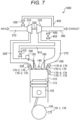
- the engine 1000 takes in air from an air inlet 210.
- the intake air passes through an intake pipe 220, is mixed with hydrogen injected from a hydrogen injection device 240 in an intake port 230, and is supplied to a combustion chamber 115 in a cylinder 110 as a gas mixture.
- the gas mixture supplied to the combustion chamber 115 is compressed by a piston 120, and is ignited by an ignition device 140 such as a diesel injection device.
- the gas mixture expands when combusted, pushes the piston 120, and causes a crankshaft 130 to rotate.
- the combusted gas mixture is discharged as combustion gas from the combustion chamber 115 to an exhaust port 280, passes through a second exhaust pipe 270 and a first exhaust pipe 260, and is discharged to the outside.
- the ignition device 140 ignites gas in the combustion chamber 115 when the piston 120 reaches a top dead center, which is, for example, immediately after having moved beyond the top dead center.
- a top dead center which is, for example, immediately after having moved beyond the top dead center.
- the engine 1000 estimates a temperature in the combustion chamber 115, e.g., the cylinder 110, when the piston 120 is at the top dead center position, and performs a control of reducing pre-ignition when the estimated temperature is higher than a reference value. As a result, the engine 1000 performs a control of reducing abnormal combustion before the abnormal combustion occurs.
- the reference value to be compared with the estimated temperature indicates a value corresponding to an ignition temperature at which hydrogen spontaneously ignites, and is determined, for example, based on the pressure level and hydrogen equivalent ratio of gas in the combustion chamber 115 (cylinder 110) and the rotation speed of the engine 1000.
- the hydrogen equivalent ratio indicates the concentration of hydrogen in gas in the combustion chamber 115, and for gas in the combustion chamber 115, indicates a value obtained by dividing a theoretical air-fuel ratio, which is an air-fuel ratio having the highest combustion efficiency in theory, by an actual air-fuel ratio, for example.
- the configuration of the engine 1000 illustrated in Fig. 1 will be described.
- the engine 1000 includes, for example, the cylinder 110, the piston 120, the crankshaft 130, a sensor 170, the hydrogen injection device 240, and a compression device 310.
- the cylinder 110 is configured to form the combustion chamber 115 surrounded by wall surfaces of the cylinder 110 and the upper surface of the piston 120.
- the cylinder 110 includes the ignition device 140, an intake valve 150, and an exhaust valve 160. Note that the upward direction in the cylinder 110 indicates a direction from the piston 120 to the ignition device 140 in the axial direction of the cylinder 110.
- the ignition device 140 is configured to ignite gas in the combustion chamber 115, such as gas containing hydrogen.
- the ignition device 140 includes, for example, a pilot liquid injection device that injects pilot liquid (e.g., light oil).
- the pilot liquid injected from the pilot liquid injection device is ignited by the temperature in the combustion chamber 115. Flame generated by ignition of the pilot liquid ignites gas in the combustion chamber 115, such as hydrogen. As a result, the gas in the combustion chamber 115 is combusted.
- the ignition device 140 may be a spark ignition device (e.g., ignition plug) that generates a spark.
- the intake valve 150 is configured to open when the gas mixture containing hydrogen is taken into the combustion chamber 115. When the intake valve 150 is opened, the gas mixture is taken into the cylinder 110 from the intake port 230.
- the exhaust valve 160 is configured to open when the combustion gas combusted in the combustion chamber 115 is discharged to the outside of the combustion chamber 115. When the exhaust valve 160 is opened, the combustion gas in the cylinder 110 is discharged to the exhaust port 280.
- the intake valve 150 and the exhaust valve 160 operate according to the angle of the crankshaft 130, for example.
- the piston 120 reciprocates in the axial direction of the cylinder 110 to compress gas in the combustion chamber 115.
- the crankshaft 130 is rotated once.
- the piston 120 reciprocates twice, for example, when gas in the combustion chamber 115 is combusted once.
- the crankshaft 130 is rotated by reciprocation of the piston 120, and transmits generated rotational force to the outside.
- the rotation speed of the engine 1000 indicates the number of rotations of the crankshaft 130 per unit time. Moreover, the rotation speed of the engine 1000 indicates the number of reciprocations of the piston 120 per unit time.
- the hydrogen injection device 240 is configured to inject hydrogen into air flowing in the intake port 230.
- the hydrogen injection device 240 injects hydrogen to generate the gas mixture of air and hydrogen.
- the generated gas mixture is supplied to the cylinder 110.
- the compression device 310 compresses air taken in from the air inlet 210.
- the compressed air is discharged to the intake pipe 220.
- the compression device 310 is connected to an exhaust turbine 320 through a shaft 330. As the shaft 330 rotates, the compression device 310 compresses air.
- the exhaust turbine 320 takes in the combustion gas discharged from the cylinder 110 through the second exhaust pipe 270, and discharges the combustion gas to the first exhaust pipe 260.
- the exhaust turbine 320 utilizes the flow of combustion gas to rotate the shaft 330.
- the engine 1000 may have a branch pipe 420 that connects the second exhaust pipe 270 and the first exhaust pipe 260 to each other.
- the branch pipe 420 discharges the combustion gas from the second exhaust pipe 270 to the first exhaust pipe 260 without the combustion gas passing through the exhaust turbine 320.
- the branch pipe 420 is provided with a branch valve 425.
- the branch valve 425 adjusts the flow rate of the combustion gas discharged from the second exhaust pipe 270 to the first exhaust pipe 260.
- the branch valve 425 adjusts the flow rate of the combustion gas passing through the branch pipe 420 to adjust the flow rate of the combustion gas passing through the exhaust turbine 320.
- the branch valve 425 controls the rotational force to be applied to the shaft 330 by the exhaust turbine 320.
- the engine 1000 may have a first exhaust recirculation pipe 410 that connects the second exhaust pipe 270 and the intake pipe 220 to each other.
- the first exhaust recirculation pipe 410 discharges the combustion gas from the second exhaust pipe 270 to the intake pipe 220, and for example, functions as a high pressure loop exhaust gas recirculation (HP-EGR).
- HP-EGR high pressure loop exhaust gas recirculation
- the first exhaust recirculation pipe 410 is provided with a first exhaust recirculation valve 415 that adjusts the flow rate of the passing combustion gas.
- the first exhaust recirculation pipe 410 may be provided with a recirculation cooling device that cools the passing combustion gas.
- the engine 1000 may have a second exhaust recirculation pipe 430 that connects the first exhaust pipe 260 and the air inlet 210 to each other.
- the second exhaust recirculation pipe 430 discharges the combustion gas from the first exhaust pipe 260 to the air inlet 210, and for example, functions as a low pressure loop exhaust gas recirculation (LP-EGR).
- the second exhaust recirculation pipe 430 is provided with a second exhaust recirculation valve 435 that adjusts the flow rate of the passing combustion gas.
- the second exhaust recirculation pipe 430 may be provided with a recirculation cooling device that cools the passing combustion gas.
- An intercooler may be provided in the intake pipe 220 connecting the compression device 310 and the intake port 230 to each other.
- the air inlet 210 may be provided with an air filter that removes a foreign substance such as dust from air taken in from the outside.
- the first exhaust pipe 260 may be provided with a removal device for removing a harmful substance from the combustion gas, such as a catalyst or a diesel particulate filter (DPF).
- a removal device for removing a harmful substance from the combustion gas such as a catalyst or a diesel particulate filter (DPF).
- the sensor 170 measures the state of the engine 1000.
- the sensor 170 includes a rotation sensor 170-1 that measures the rotation speed of the crankshaft 130.
- the rotation sensor 170-1 may measure the rotation angle of the crankshaft 130, for example, a rotation angle with reference to the rotation angle when the piston 120 is at the top dead center position being "0" degrees.
- the sensor 170 measures the state of gas in the engine 1000, which is, for example, the states of the gas mixture and the combustion gas, such as a pressure value indicating the level of the pressure and a temperature.
- the sensor 170 includes an intake pressure sensor 170-2 configured to measure the pressure value of the gas mixture supplied to the cylinder 110.
- the sensor 170 includes an intake temperature sensor 170-3 configured to measure the temperature of the gas mixture supplied to the cylinder 110.
- the intake temperature sensor 170-3 may measure the temperature of the wall surface of the intake port 230 to determine the temperature of the gas mixture.
- the intake pressure sensor 170-2 and the intake temperature sensor 170-3 are provided, for example, in the intake port 230.
- the intake pressure sensor 170-2 and the intake temperature sensor 170-3 may be provided, for example, in the intake pipe 220.
- the senor 170 may have a cylinder internal pressure sensor 170-4 configured to measure the pressure value of gas in the combustion chamber 115, such as the gas mixture and the combustion gas.
- the cylinder internal pressure sensor 170-4 is provided at a position where the pressure value of gas in the combustion chamber 115 can be measured when the piston 120 is at the top dead center position.
- the cylinder internal pressure sensor 170-4 is arranged on the upper side in the cylinder 110, for example, near the intake valve 150 or the exhaust valve 160.
- the sensor 170 may include an exhaust pressure sensor 170-5 configured to measure the pressure value of the combustion gas discharged from the cylinder 110.
- the sensor 170 may include an exhaust temperature sensor 170-6 configured to measure the temperature of the combustion gas discharged from the cylinder 110.
- the exhaust temperature sensor 170-6 may measure the temperature of the wall surface of the exhaust port 280 to determine the temperature of the combustion gas.
- the exhaust pressure sensor 170-5 and the exhaust temperature sensor 170-6 are provided, for example, in the exhaust port 280.
- the exhaust pressure sensor 170-5 and the exhaust temperature sensor 170-6 may be provided in the second exhaust pipe 270.
- the engine 1000 further includes a control device 500 illustrated in Fig. 2 .
- the control device 500 controls operation of the engine 1000.
- the control device 500 includes, for example, an arithmetic device 520, a communication device 530, and a storage device 540.
- the communication device 530 communicates with each device provided in the engine 1000. For example, the communication device 530 acquires a signal indicating information measured by the sensor 170. In addition, the communication device 530 outputs a signal for igniting gas in the combustion chamber 115 to the ignition device 140.
- the communication device 530 may output a signal for controlling the compression ratio of air by the compression device 310.
- the communication device 530 may transmit and receive a signal in accordance with a serial communication protocol defined for a device on which the engine 1000 is mounted, such as a controller area network (CAN) of a vehicle. Further, the communication device 530 may include various interfaces for communicating with an external terminal, such as a network interface card (NIC) and a universal serial bus (USB).
- a serial communication protocol defined for a device on which the engine 1000 is mounted, such as a controller area network (CAN) of a vehicle.
- CAN controller area network
- the communication device 530 may include various interfaces for communicating with an external terminal, such as a network interface card (NIC) and a universal serial bus (USB).
- NIC network interface card
- USB universal serial bus
- the storage device 540 stores various types of data for controlling the engine 1000, such as a control program 600 and spontaneous ignition temperature data 610.
- the storage device 540 is used as a non-transitory tangible storage medium that stores the control program 600.
- the control program 600 may be provided as a computer program product recorded in a computer-readable storage medium 1, or may be provided as a computer program product downloadable from a server.
- the spontaneous ignition temperature data 610 indicates a first reference value determined based on the pressure value of gas in the combustion chamber 115, the hydrogen equivalent ratio of gas in the combustion chamber 115, and the rotation speed of the engine 1000.
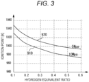
- the first reference value is expressed according to an ignition point at which hydrogen spontaneously ignites.
- the ignition point of hydrogen changes according to the hydrogen equivalent ratio and the pressure value.
- a first spontaneous ignition line 910 indicates a relationship between the hydrogen equivalent ratio and the ignition point when the pressure value is 10 MPa.
- a second spontaneous ignition line 920 indicates a relationship between the hydrogen equivalent ratio and the ignition point when the pressure value is 5 MPa.
- predetermined time is required until the hydrogen spontaneously ignites after the temperature has reached the ignition point.
- the spontaneous ignition temperature data 610 indicates a relationship among the pressure value, hydrogen equivalent ratio, and temperature of gas when hydrogen is ignited in this period.
- the first reference value indicated by the spontaneous ignition temperature data 610 indicates a value obtained by subtracting a predetermined value from a temperature at which hydrogen is ignited, which is determined according to the pressure value and hydrogen equivalent ratio of gas in this period.
- the predetermined value to be subtracted is set so that ignition of hydrogen can be suppressed with a margin.
- the first reference value indicated by the spontaneous ignition temperature data 610 decreases because the ignition point of hydrogen decreases as the hydrogen equivalent ratio increases.
- the first reference value decreases as the pressure value increases. Since the period in which the pressure value and the temperature are the highest becomes shorter as the rotation speed of the engine 1000 increases, the first reference value increases as the rotation speed increases.
- the spontaneous ignition temperature data 610 indicates the first reference value according to the pressure value and hydrogen equivalent ratio of gas in the combustion chamber 115 and the rotation speed of the engine 1000.
- the spontaneous ignition temperature data 610 may be determined by simulation or by a test for hydrogen ignition.
- the spontaneous ignition temperature data 610 may include a lookup table that outputs the first reference value using the pressure value and hydrogen equivalent ratio of gas and the rotation speed of the engine 1000 as arguments.
- the arithmetic device 520 illustrated in Fig. 2 reads the control program 600 from the storage device 540 and executes the control program 600 to perform various types of data processing for controlling the engine 1000.
- the arithmetic device 520 includes an electronic control unit (ECU).
- the electronic control unit may be implemented by the arithmetic device 520 and the storage device 540, or may be implemented by the control device 500.
- the arithmetic device 520 reads and executes the control program 600 to implement an abnormal combustion estimation unit 550 and a control unit 560 as illustrated in Fig. 4 .
- the abnormal combustion estimation unit 550 estimates occurrence of the abnormal combustion based on the pressure value, hydrogen equivalent ratio, and temperature of gas in the combustion chamber 115 and the rotation speed of the engine 1000.
- the control unit 560 controls the engine 1000 to reduce occurrence of the abnormal combustion.
- the abnormal combustion estimation unit 550 includes a temperature estimation unit 551, a reference value determination unit 552, and a determination unit 553.
- the temperature estimation unit 551 estimates a compression temperature indicating the temperature of gas when the piston 120 is at the top dead center position.
- the reference value determination unit 552 determines the first reference value based on the pressure value and hydrogen equivalent ratio of gas and the rotation speed of the engine 1000.
- the determination unit 553 compares the determined first reference value with the estimated compression temperature to determine whether or not the abnormal combustion has occurred.
- Step S110 the temperature estimation unit 551 implemented by the arithmetic device 520 estimates the compression temperature of gas in the combustion chamber 115 based on the temperature of the gas mixture.
- the temperature estimation unit 551 acquires the temperature measured by the intake temperature sensor 170-3 illustrated in Fig. 1 as the temperature of the gas mixture taken into the cylinder 110.
- the temperature estimation unit 551 acquires the temperature measured when the intake valve 150 is opened as the temperature of the gas mixture taken into the cylinder 110.
- the temperature estimation unit 551 determines the compression temperature T comp based on Equation (1).
- Equation (1) is derived based on the first law of thermodynamics, the ideal gas law, and the polytropic relationship equation.
- T comp T in ⁇ ⁇ n ⁇ 1
- T in indicates the temperature of the gas mixture taken into the cylinder 110
- ⁇ indicates the geometrical compression ratio of the combustion chamber 115
- n indicates a polytropic index.
- the reference value determination unit 552 estimates, based on the pressure value of the gas mixture, a compression pressure value indicating the pressure value in the combustion chamber 115 when the piston 120 is at the top dead center position. For example, the reference value determination unit 552 acquires the pressure value measured by the intake pressure sensor 170-2 illustrated in Fig. 1 as the pressure value of the gas mixture taken into the cylinder 110. For example, the reference value determination unit 552 acquires the pressure value measured when the intake valve 150 is opened as the pressure value of the gas mixture taken into the cylinder 110. The reference value determination unit 552 determines the compression pressure value P comp based on Equation (2).
- Equation (2) is derived based on the first law of thermodynamics, the ideal gas law, and the polytropic relationship equation.
- P comp P in ⁇ ⁇ n
- P in indicates the pressure value of the gas mixture taken into the cylinder 110
- ⁇ indicates the geometrical compression ratio of the combustion chamber 115
- n indicates a polytropic index.
- the reference value determination unit 552 determines the mass flow rate G Air of air based on the temperature of the gas mixture, the pressure value of the gas mixture, and the rotation speed of the engine 1000. For example, the reference value determination unit 552 determines the mass flow rate G Air of air based on the temperature and pressure value of the gas mixture taken into the cylinder 110 and the rotation speed of the engine 1000. For example, the reference value determination unit 552 uses the values used in Steps S110 and S120 as the temperature and pressure value of the gas mixture taken into the cylinder 110. In addition, the reference value determination unit 552 acquires the rotation speed of the engine 1000 measured from the rotation sensor 170-1. For example, the reference value determination unit 552 determines the mass flow rate G Air of air using Equation (4).
- Equation (4) is derived based on the ideal gas law.
- G Air ⁇ vcor ⁇ P in ⁇ V swpt R ⁇ T in ⁇ 60 ⁇ N 2
- ⁇ vcor indicates the volumetric efficiency of air
- V swpt indicates a total stroke volume in the cylinder 110
- R indicates a gas constant
- N indicates the rotation speed of the engine 1000.
- P in indicates the pressure value of the gas mixture taken into the cylinder 110
- T in indicates the temperature of the gas mixture taken into the cylinder 110.
- the volumetric efficiency ⁇ vcor is determined from the pressure of the gas mixture, the injection amount of hydrogen, and the like by a known method.
- the volumetric efficiency ⁇ vcor is calculated, in a test for the engine 1000, based on an air flow rate measured while changing the rotation speed, the hydrogen injection amount, the air excess ratio, and the like.
- R indicates a fixed value such as 287
- V swpt indicates a fixed value according to the number of cylinders 110 and the shape of the cylinders 110 in the engine 1000.
- the reference value determination unit 552 determines the hydrogen equivalent ratio of gas in the combustion chamber 115 based on the determined mass flow rate G Air of air and Equation (3).
- the reference value determination unit 552 determines the first reference value based on the spontaneous ignition temperature data 610. For example, the reference value determination unit 552 acquires, from the spontaneous ignition temperature data 610, the first reference value corresponding to the estimated gas pressure value P comp , the hydrogen equivalent ratio ⁇ , and the rotation speed N of the engine 1000.
- Step S150 the determination unit 553 determines whether or not the abnormal combustion occurs, based on the determined compression temperature T comp and the first reference value. For example, the determination unit 553 determines whether or not the compression temperature T comp is greater than the first reference value. When the compression temperature T comp is greater than the first reference value, the determination unit 553 determines that the abnormal combustion occurs. When the compression temperature T comp is the first reference value or less, the determination unit 553 determines that the abnormal combustion does not occur. When it is determined that the abnormal combustion does not occur, the processing returns to Step S110 and is repeated. When it is determined that the abnormal combustion occurs, the processing proceeds to Step S160.
- Step S160 the control unit 560 generates a first control signal for reducing occurrence of the abnormal combustion, and outputs the first control signal to a corresponding device.
- the control unit 560 generates a first control signal for delaying timing of igniting the gas mixture by the ignition device 140.
- the ignition device 140 delays the timing of igniting the gas mixture.
- the ignition device 140 delays timing of injecting the pilot liquid (e.g., light oil).
- the control unit 560 may generate a first control signal for controlling the hydrogen equivalent ratio.
- the control unit 560 generates a first control signal for increasing the compression ratio of air by the compression device 310 illustrated in Fig. 1 .
- the control unit 560 generates, for example, a first control signal for decreasing the combustion gas passing through the branch valve 425.
- the branch valve 425 decreases the cross-sectional area of a flow path in which the combustion gas flows such that the passing combustion gas decreases.
- the combustion gas passing through the branch valve 425 decreases, the combustion gases passing through the exhaust turbine 320 increases.
- the rotational force of the shaft 330 increases, and the compression ratio of air by the compression device 310 increases. Since the air flowing into the intake port 230 increases, the hydrogen equivalent ratio decreases.
- the control unit 560 may generate a first control signal for decreasing the combustion gas passing through the first exhaust recirculation valve 415.
- the first exhaust recirculation valve 415 decreases the cross-sectional area of the flow path in which the combustion gas flows such that the passing combustion gas decreases.
- the air flowing into the intake port 230 increases. Since the air flowing into the intake port 230 increases, the hydrogen equivalent ratio decreases.
- the control unit 560 may generate a first control signal for decreasing the injection amount of hydrogen from the hydrogen injection device 240. When the injection amount of hydrogen decreases, the control unit 560 may generate a second control signal for increasing the pilot liquid discharged from the ignition device 140 according to a decrease in hydrogen. As a result, occurrence of the abnormal combustion is reduced while the output of the engine 1000 is maintained.
- the control device 500 estimates occurrence of the abnormal combustion by comparing the temperature of gas in the combustion chamber 115 with the first reference value.
- the control device 500 controls the engine 1000 to reduce occurrence of the abnormal combustion.
- the control device 500 can reduce occurrence of the abnormal combustion before occurrence of the abnormal combustion.
- occurrence of abnormal combustion may be determined based on a pressure value in a cylinder 110, the temperature of a gas mixture taken into the cylinder 110, and the rotation speed of an engine 1000.
- the configuration of the engine 1000 is similar to that of the first embodiment, and therefore, description thereof will be omitted.
- W g indicates the total number of moles of working gas, and is determined by Equation (6).
- W g n IVC
- n IVC indicates the number of moles of gas in the cylinder 110 when the intake valve 150 is closed.
- n IVC is determined by Equation (7) derived based on the ideal gas law.
- P IVC may indicate the compression value measured by the cylinder internal pressure sensor 170-4 when the intake valve 150 is opened.
- Vrvc indicates the capacity of the combustion chamber 115 when the intake valve 150 is closed, and is determined based on the shape of the cylinder 110 and the crank angle indicating the rotation angle of the crankshaft 130.
- T in_cyl indicates the temperature of gas in the combustion chamber 115, such as the gas mixture and the combustion gas, when the intake valve 150 is closed.
- T in_cyl is substituted for the temperature T in measured by the intake temperature sensor 170-3 when the intake valve 150 is closed.
- T in_cyl may be substituted for the temperature T in measured by the intake temperature sensor 170-3 when the intake valve 150 is opened.
- Step S120 illustrated in Fig. 5 the reference value determination unit 552 uses the pressure value measured by the cylinder internal pressure sensor 170-4 as the compression pressure value P comp . For example, when the piston 120 is at the top dead center position, the reference value determination unit 552 determines the pressure value measured by the cylinder internal pressure sensor 170-4 as the compression pressure value P comp .
- the reference value determination unit 552 determines the hydrogen equivalent ratio using the pressure value measured by the cylinder internal pressure sensor 170-4 when the intake valve 150 is closed. For example, the reference value determination unit 552 uses the pressure value P IVC measured by the cylinder internal pressure sensor 170-4 when the intake valve 150 is closed as P in indicating the pressure value of the gas mixture taken into the cylinder 110 according to Equation (4). As P in , the pressure value measured by the cylinder internal pressure sensor 170-4 when the intake valve 150 is opened may be used. As a result, the reference value determination unit 552 determines the hydrogen equivalent ratio according to Equation (3) and Equation (4).
- Step S140 to Step S160 Since the processing from Step S140 to Step S160 is similar to that of the first embodiment, description thereof will be omitted.
- control device 500 can estimate occurrence of the abnormal combustion based on the pressure value in the cylinder 110, the temperature of the gas mixture taken into the cylinder 110, and the rotation speed of the engine 1000.
- control device 500 may estimate occurrence of the abnormal combustion based on the pressure value in the cylinder 110, the temperature of the gas mixture taken into the cylinder 110, the temperature of the combustion gas discharged from the cylinder 110, and the rotation speed of the engine 1000.
- the reference value determination unit 552 of the control device 500 may perform zero point correction for the pressure value measured by the cylinder internal pressure sensor 170-4 by using the pressure value measured by the intake pressure sensor 170-2. For example, when the intake valve 150 is opened, the reference value determination unit 552 determines a correction value of the pressure value measured by the cylinder internal pressure sensor 170-4 such that the pressure value measured by the cylinder internal pressure sensor 170-4 is equal to the pressure value measured by the intake pressure sensor 170-2. The reference value determination unit 552 acquires the pressure value in the cylinder 110 by adding the correction value to the pressure value measured by the cylinder internal pressure sensor 170-4.
- the reference value determination unit 552 may perform zero point correction for the pressure value measured by the cylinder internal pressure sensor 170-4 by using the pressure value measured by the exhaust pressure sensor 170-5.
- the reference value determination unit 552 may perform zero point correction for the pressure value measured by the cylinder internal pressure sensor 170-4 by using two pressure values measured by the intake pressure sensor 170-2 and the exhaust pressure sensor 170-5.
- the reference value determination unit 552 may determine the correction value such that the sum of a difference between the pressure value of the cylinder internal pressure sensor 170-4 and the pressure value of the intake pressure sensor 170-2 when the intake valve 150 is opened and a difference between the pressure value of the cylinder internal pressure sensor 170-4 and the pressure value of the exhaust pressure sensor 170-5 when the exhaust valve 160 is opened is minimized.
- a reference value determination unit 552 of a control device 500 may determine a hydrogen equivalent ratio by estimating the blow-through amount of a gas mixture, which has been taken into a cylinder 110 and blown through the cylinder 110 to an exhaust port 280 before the gas mixture is combusted.
- the configuration of the engine 1000 is similar to that of the first embodiment, and therefore, description thereof will be omitted.
- Step S 110 and Step S 120 illustrated in Fig. 5 Since the processing in Step S 110 and Step S 120 illustrated in Fig. 5 is similar to that in the first or second embodiment, description thereof will be omitted.
- Step S130 the reference value determination unit 552 determines the hydrogen equivalent ratio ⁇ according to Equation (9).
- n short_ratio indicates the ratio of the gas mixture supplied to the cylinder 110 to the gas blown into the exhaust port 280 before combustion, for example, the ratio of the gas mixture to the combustion gas, is calculated according to Equation (10).
- n air indicates the number of moles of air supplied to the cylinder 110, and is determined based on the temperature and pressure of the gas mixture in the intake port 230 when the intake valve 150 is opened.
- n fuel indicates the number of moles of hydrogen supplied to the cylinder 110, and is determined based on the injection amount of hydrogen instructed to the hydrogen injection device 240 by the control device 500.
- n res P ex + 101.3 ⁇ V comp R g ⁇ T ex + 273.15
- P ex indicates the pressure of the combustion gas discharged from the cylinder 110, and indicates the pressure value measured by the exhaust pressure sensor 170-5 when the exhaust valve 160 is opened.
- P ex the pressure value measured by the cylinder internal pressure sensor 170-4 when the exhaust valve 160 is opened may be used.
- V comp indicates the volume of the combustion chamber 115 at a crank angle of 0 degrees.
- R g indicates a gas constant.
- T ex indicates the temperature of the combustion gas discharged from the cylinder 110, and indicates the temperature measured by the exhaust temperature sensor 170-6 when the exhaust valve 160 is opened.
- the reference value determination unit 552 determines the hydrogen equivalent ratio using the values measured by the intake pressure sensor 170-2, the intake temperature sensor 170-3, the exhaust pressure sensor 170-5, and the exhaust temperature sensor 170-6.
- the reference value determination unit 552 may determine the hydrogen equivalent ratio using the values measured by the cylinder internal pressure sensor 170-4, the intake temperature sensor 170-3, and the exhaust temperature sensor 170-6.
- Step S140 to Step S160 Since the processing from Step S140 to Step S160 is similar to that of the first embodiment, description thereof will be omitted.
- control device 500 can estimate occurrence of abnormal combustion, considering the blow-through amount of the gas mixture, which has been taken into the cylinder 110 and blown through the cylinder 110 to the exhaust port 280 before the gas mixture is combusted.
- the control device 500 may estimate occurrence of the abnormal combustion, considering the flow rate of the combustion gas passing through the first exhaust recirculation pipe 410 and/or the second exhaust recirculation pipe 430 illustrated in Fig. 1 .
- the control device 500 determines the hydrogen equivalent ratio using the flow rate of the combustion gas passing through the first exhaust recirculation pipe 410 and/or the second exhaust recirculation pipe 430.
- the control device 500 changes Equation (10) and Equation (11) to equations obtained by adding the number of moles of the combustion gas passing through the first exhaust recirculation pipe 410 and/or the second exhaust recirculation pipe 430 to determine the hydrogen equivalent ratio.
- the engine 1000 has a flow rate measurement device that measures the flow rate of the combustion gas passing through the first exhaust recirculation pipe 410 and/or the second exhaust recirculation pipe 430.
- an engine 1000 includes a combustion chamber temperature sensor 170-7 that measures a temperature corresponding to the temperature in the combustion chamber 115.
- the combustion chamber temperature sensor 170-7 is provided, for example, outside a wall surface of a cylinder 110.
- the combustion chamber temperature sensor 170-7 may be provided at any position at which the temperature corresponding to the temperature in the combustion chamber 115 can be measured, such as a position in the cylinder 110.
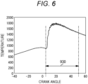
- the temperature estimation unit 551 illustrated in Fig. 4 determines the temperature of combustion gas in the combustion period 930 based on the temperature measured by the combustion chamber temperature sensor 170-7.
- a reference value determination unit 552 determines a second reference value for comparison with the temperature of the combustion gas in the combustion period 930 based on the temperature and hydrogen equivalent ratio of the gas mixture and the rotation speed of the engine 1000.
- a determination unit 553 determines whether or not the abnormal combustion occurs, based on the temperature of the combustion gas in the combustion period 930 and the second reference value. When it is determined that the abnormal combustion occurs, a control unit 560 performs control for reducing the abnormal combustion.
- a method for controlling the engine 1000 will be described, in which determination using the temperature of the combustion gas in the combustion period 930 is added to the processing of the first embodiment.
- the arithmetic device 520 executes the control program 600 to execute processing illustrated in Figs. 8A and 8B , which is part of the control method. Since the processing from Step S110 to Step S140 is similar to that of the first embodiment, description thereof will be omitted.
- Step S150 the determination unit 553 determines whether or not the abnormal combustion occurs, based on the determined compression temperature T comp and the first reference value. For example, the determination unit 553 determines whether or not the compression temperature T comp is greater than the first reference value. When the compression temperature T comp is greater than the first reference value, the determination unit 553 determines that the abnormal combustion occurs. When the compression temperature T comp is the first reference value or less, the determination unit 553 determines that the abnormal combustion does not occur. When it is determined that the abnormal combustion occurs, the processing proceeds to Step S160. Since the processing in Step S160 is similar to that of the first embodiment, description thereof will be omitted. When it is determined that the abnormal combustion does not occur, the processing proceeds to Step S210 illustrated in Fig. 8B .
- the temperature estimation unit 551 determines the average temperature of the combustion gas in the combustion period 930 based on the temperature measured by the combustion chamber temperature sensor 170-7. For example, the temperature estimation unit 551 estimates, as the average temperature of the combustion gas, the average of the temperature measured by the combustion chamber temperature sensor 170-7 in the combustion period 930.
- the combustion period 930 indicates the period in which the gas mixture is combusted, and is determined in advance.
- the reference value determination unit 552 determines the second reference value for comparison with the average temperature of the combustion gas in the combustion period 930 based on the first reference value.
- the second reference value is determined by multiplying the first reference value, which corresponds to the ignition point where hydrogen spontaneously ignites, by a predetermined coefficient and subtracting a predetermined value from the product of the predetermined coefficient and the first reference value.
- the coefficient to be multiplied is determined based on the average temperature of the combustion gas in the combustion period 930 and the compression temperature of gas in the combustion chamber 115 when the piston 120 is at the top dead center position when the gas mixture is normally combusted.
- the coefficient indicates, for example, a value obtained by dividing the average temperature of the combustion gas in the combustion period 930 by the compression temperature.
- the coefficient may be a fixed value determined in advance by, e.g., a test or simulation.
- the average temperature and compression temperature used for the coefficient may be temperatures measured when combustion is performed only with the pilot liquid (e.g., light oil) without injecting hydrogen into gas to be supplied to the cylinder 110.
- the predetermined value to be subtracted is set so that ignition of hydrogen can be restrained with a margin.
- Step S230 the determination unit 553 determines whether or not the abnormal combustion occurs, based on the average temperature of the combustion gas in the combustion period 930 and the second reference value. For example, the determination unit 553 determines whether or not the average temperature is greater than the second reference value. When the average temperature is greater than the second reference value, the determination unit 553 determines that the abnormal combustion occurs. When the average temperature is the second reference value or less, the determination unit 553 determines that the abnormal combustion does not occur. When it is determined that the abnormal combustion does not occur, the processing returns to Step S110 illustrated in Fig. 8A and is repeated. When it is determined that the abnormal combustion occurs, the processing proceeds to Step S240.
- Step S240 the control unit 560 generates a first control signal for reducing occurrence of the abnormal combustion, and outputs the first control signal to a corresponding device. Since the processing in Step S240 is similar to that in Step S160, description thereof will be omitted.
- the engine 1000 can reduce the abnormal combustion which occurs when the temperature in the combustion chamber 115 is low when the piston 120 is at the top dead center position.
- the reference value determination unit 552 may determine the first reference value by arithmetic processing using the pressure value of gas in the combustion chamber 115, the hydrogen equivalent ratio of gas in the combustion chamber 115, and the rotation speed of the engine 1000. In this case, the spontaneous ignition temperature data 610 may be omitted.
- the reference value determination unit 552 may determine the first reference value based on which the determination unit 553 can estimate occurrence of the abnormal combustion by comparison with the compression temperature T comp .
- the reference value determination unit 552 may determine, as the first reference value, the temperature at which hydrogen ignites based on the pressure value of gas in the combustion chamber 115, the hydrogen equivalent ratio of gas in the combustion chamber 115, and the rotation speed of the engine 1000. In this case, the determination unit 553 estimates that the abnormal combustion occurs when a difference between the compression temperature T comp and the first reference value is less than a predetermined value.
- the reference value determination unit 552 determines the second reference value for comparison with the value of the average temperature of the combustion gas in the combustion period 930 to find which value is greater or smaller has been described, but the present invention is not limited thereto.
- the reference value determination unit 552 may determine the second reference value based on which the determination unit 553 can estimate occurrence of the abnormal combustion by comparison with the average temperature. For example, the reference value determination unit 552 may determine the first reference value or the second reference value obtained by dividing the temperature at which hydrogen ignites by the compression temperature at which the gas mixture is normally combusted.
- the determination unit 553 determines an evaluation value obtained by dividing the average temperature in the combustion period 930 by the average temperature in the combustion period 930 when the gas mixture is normally combusted. When a difference between the second reference value and the evaluation value is less than a predetermined value, the determination unit 553 estimates that the abnormal combustion occurs.
- the gas mixture supplied to the cylinder 110 may contain fuel other than hydrogen.
- a fuel injection device that injects fuel other than hydrogen may be provided in the intake port 230 illustrated in Fig. 1 .
- the control unit 560 of the control device 500 may generate a second control signal for increasing the injection amount of fuel other than hydrogen, such as the pilot liquid, in the cylinder 110 according to the amount of decrease in hydrogen. As a result, occurrence of the abnormal combustion is reduced while the output of the engine 1000 is maintained.
- the engine 1000 may include a plurality of cylinders 110, and may include an intake manifold between the intake pipe 220 and the intake port 230.
- the intake pressure sensor 170-2 and the intake temperature sensor 170-3 may be provided in either the intake port 230 or the intake pipe 220.
- the engine 1000 may include an exhaust manifold between the exhaust port 280 and the second exhaust pipe 270.
- the exhaust pressure sensor 170-5 and the exhaust temperature sensor 170-6 may be provided in either the exhaust port 280 or the second exhaust pipe 270.
- the piston 120 may reciprocate once when gas in the combustion chamber 115 is combusted once.
- the reference value determination unit 552 calculates G Air according to an equation obtained by doubling the right side of Equation (4).
- the embodiments and modifications described above are examples, and the configurations described in the embodiments and the modifications may be arbitrarily changed and/or arbitrarily combined as long as the functions are not impaired. Further, as long as necessary functions can be implemented, some functions described in the embodiments and the modifications may be omitted. For example, all or some of the compression device 310, the first exhaust recirculation pipe 410, and the second exhaust recirculation pipe 430 may be omitted. In a case where the compression device 310 is omitted, the exhaust turbine 320, the shaft 330, and the branch pipe 420 are also omitted.
- the sensor 170 that measures the value which is not used in the processing of the arithmetic device 520 of the control device 500 may be omitted.
- An engine according to a first aspect includes
- An engine according to a second aspect is the engine according to the first aspect, in which
- An engine according to a third aspect is the engine according to the second aspect, in which
- An engine according to a fourth aspect is the engine according to the first aspect, which further includes
- An engine according to a fifth aspect is the engine according to the fourth aspect, in which
- An engine according to a sixth aspect is the engine according to the fifth aspect, in which the temperature estimation unit estimates the compression temperature based on the temperature of the gas mixture and the second pressure value of the gas in the cylinder.
- An engine according to a seventh aspect is the engine according to any one of the third, fifth, and sixth aspects, which further includes
- An engine according to an eighth aspect is the engine according to any one of the second to seventh aspects, in which
- An engine according to a ninth aspect is the engine according to any one of the first to eighth aspects, which further includes
- a control device includes
- a control device is the control device according to the tenth aspect, in which
- a control device is the control device according to the tenth or eleventh aspect, in which
- a control program causes an arithmetic device to execute
Landscapes
- Engineering & Computer Science (AREA)
- Chemical & Material Sciences (AREA)
- Combustion & Propulsion (AREA)
- Mechanical Engineering (AREA)
- General Engineering & Computer Science (AREA)
- Oil, Petroleum & Natural Gas (AREA)
- Chemical Kinetics & Catalysis (AREA)
- General Chemical & Material Sciences (AREA)
- Health & Medical Sciences (AREA)
- Biomedical Technology (AREA)
- Theoretical Computer Science (AREA)
- Signal Processing (AREA)
- Combined Controls Of Internal Combustion Engines (AREA)
- Electrical Control Of Air Or Fuel Supplied To Internal-Combustion Engine (AREA)
- Electrical Control Of Ignition Timing (AREA)
- Output Control And Ontrol Of Special Type Engine (AREA)
Abstract
Description
- The present invention relates to an engine, a control device, and a control program.
- In recent years, study has been conducted on a hydrogen engine that obtains power using hydrogen-containing fuel. In the hydrogen engine, hydrogen premixed gas obtained by mixing of hydrogen and air is supplied to a cylinder, and is combusted in the cylinder. In this manner, power is obtained. When the air-fuel ratio of the hydrogen premixed gas is out of a proper range, abnormal combustion, such as pre-ignition in which ignition is made earlier than designed ignition timing, knocking, or backfire, may occur. Since the abnormal combustion might damage the engine, study has been conducted on reduction in the abnormal combustion.
- For example,
Patent Document 1 discloses a technique of detecting occurrence of abnormal combustion by measuring a pressure in a cylinder of an engine. - For example,
Patent Document 2 discloses a technique of controlling an engine to be driven in a state in which the temperature of a cylinder wall surface is in a temperature range in which abnormal combustion is less likely to occur. -
- Patent Document 1:
JP-A-2010-71284 - Patent Document 2:
WO 2013/118244 A - Since the technique described in
Patent Document 1 detects occurrence of the abnormal combustion, it is difficult to reduce occurrence of the abnormal combustion before the abnormal combustion starts. In addition, the technique described inPatent Document 2 drives the engine in the temperature range in which the abnormal combustion is less likely to occur, and does not reduce occurrence of the abnormal combustion before the abnormal combustion starts. - In view of the above-described situation, an object of the present disclosure is to estimate occurrence of abnormal combustion before the abnormal combustion starts. Other objects can be understood from the following description and explanation of embodiments.
- Hereinafter, means for solving the problem will be described using numbers and reference signs used in embodiments of the invention. These numbers and reference signs are added in parentheses for reference in order to show an example of a correspondence relationship between description in the claims and description in the embodiments of the invention. Thus, the claims shall not be interpreted in a limited manner by the parenthesized description.
- An engine (1000) according to an embodiment for accomplishing the above-described object includes a cylinder (110), a piston (120), an ignition device (140), a rotation sensor (170-1), an intake temperature sensor (170-3), an intake pressure sensor (170-2), and a control device (500). The cylinder (110) combusts a gas mixture containing hydrogen inside. The piston (120) reciprocates in the cylinder (110). The ignition device (140) ignites the gas mixture. The rotation sensor (170-1) measures the rotation speed of a crankshaft (130). The intake temperature sensor (170-3) measures the temperature of the gas mixture. The intake pressure sensor (170-2) measures a first pressure value of the gas mixture. The control device (500) controls the hydrogen equivalent ratio of hydrogen contained in the gas mixture and/or timing of igniting the gas mixture based on the rotation speed, the temperature of the gas mixture, and the first pressure value of the gas mixture.
- A control device (500) according to an embodiment for accomplishing the above-described object includes an abnormal combustion estimation unit (550) and a control unit (560). The abnormal combustion estimation unit (550) estimates abnormal combustion in a cylinder (110) included in an engine (1000) based on the compression pressure of gas in the cylinder (110), the compression temperature of gas in the cylinder (110), the hydrogen equivalent ratio of gas in the cylinder (110), and the rotation speed of the engine (1000). When the abnormal combustion is estimated, the control unit (560) generates a first control signal for controlling the hydrogen equivalent ratio and/or timing of igniting gas in the cylinder (110).
- A control program (600) according to an embodiment for accomplishing the above-described object causes an arithmetic device (520) to execute estimating abnormal combustion in a cylinder (110) included in an engine (1000) based on the compression pressure of gas in the cylinder (110), the compression temperature of gas in the cylinder (110), the hydrogen equivalent ratio of gas in the cylinder (110), and the rotation speed of the engine (1000). When the abnormal combustion is estimated, the control program (600) causes the arithmetic device (520) to execute generating a first control signal for controlling the hydrogen equivalent ratio and/or timing of igniting gas in the cylinder (110).
- According to the above-described embodiments, occurrence of the abnormal combustion can be estimated before the abnormal combustion starts.
-
-
Fig. 1 is a view illustrating the configuration of an engine according to an embodiment; -
Fig. 2 is a diagram illustrating the configuration of a control device according to the embodiment; -
Fig. 3 is a graph illustrating a relationship among the ignition point of hydrogen, a hydrogen equivalent ratio, and the pressure value of a gas mixture; -
Fig. 4 is a diagram illustrating functional blocks implemented by the control device according to the embodiment; -
Fig. 5 is a flowchart illustrating processing by the control device according to the embodiment; -
Fig. 6 is a graph illustrating a relationship between the temperature of gas in a combustion chamber and a crank angle in the embodiment; -
Fig. 7 is a view illustrating the configuration of an engine according to an embodiment; -
Fig. 8A is a flowchart illustrating processing by a control device according to the embodiment; and -
Fig. 8B is a flowchart illustrating the processing by the control device according to the embodiment. - An
engine 1000 according to the present embodiment of the present invention will be described with reference to the drawings. As illustrated inFig. 1 , theengine 1000 takes in air from anair inlet 210. The intake air passes through anintake pipe 220, is mixed with hydrogen injected from ahydrogen injection device 240 in anintake port 230, and is supplied to acombustion chamber 115 in acylinder 110 as a gas mixture. The gas mixture supplied to thecombustion chamber 115 is compressed by apiston 120, and is ignited by anignition device 140 such as a diesel injection device. The gas mixture expands when combusted, pushes thepiston 120, and causes acrankshaft 130 to rotate. The combusted gas mixture is discharged as combustion gas from thecombustion chamber 115 to anexhaust port 280, passes through asecond exhaust pipe 270 and afirst exhaust pipe 260, and is discharged to the outside. - Here, the
ignition device 140 ignites gas in thecombustion chamber 115 when thepiston 120 reaches a top dead center, which is, for example, immediately after having moved beyond the top dead center. However, when the temperature of thecombustion chamber 115 increases, pre-ignition in which hydrogen contained in gas in thecombustion chamber 115 is combusted might occur before thepiston 120 reaches the top dead center. Thus, theengine 1000 estimates a temperature in thecombustion chamber 115, e.g., thecylinder 110, when thepiston 120 is at the top dead center position, and performs a control of reducing pre-ignition when the estimated temperature is higher than a reference value. As a result, theengine 1000 performs a control of reducing abnormal combustion before the abnormal combustion occurs. Note that the reference value to be compared with the estimated temperature indicates a value corresponding to an ignition temperature at which hydrogen spontaneously ignites, and is determined, for example, based on the pressure level and hydrogen equivalent ratio of gas in the combustion chamber 115 (cylinder 110) and the rotation speed of theengine 1000. The hydrogen equivalent ratio indicates the concentration of hydrogen in gas in thecombustion chamber 115, and for gas in thecombustion chamber 115, indicates a value obtained by dividing a theoretical air-fuel ratio, which is an air-fuel ratio having the highest combustion efficiency in theory, by an actual air-fuel ratio, for example. - The configuration of the
engine 1000 illustrated inFig. 1 will be described. Theengine 1000 includes, for example, thecylinder 110, thepiston 120, thecrankshaft 130, asensor 170, thehydrogen injection device 240, and acompression device 310. Thecylinder 110 is configured to form thecombustion chamber 115 surrounded by wall surfaces of thecylinder 110 and the upper surface of thepiston 120. Thecylinder 110 includes theignition device 140, anintake valve 150, and anexhaust valve 160. Note that the upward direction in thecylinder 110 indicates a direction from thepiston 120 to theignition device 140 in the axial direction of thecylinder 110. - The
ignition device 140 is configured to ignite gas in thecombustion chamber 115, such as gas containing hydrogen. Theignition device 140 includes, for example, a pilot liquid injection device that injects pilot liquid (e.g., light oil). The pilot liquid injected from the pilot liquid injection device is ignited by the temperature in thecombustion chamber 115. Flame generated by ignition of the pilot liquid ignites gas in thecombustion chamber 115, such as hydrogen. As a result, the gas in thecombustion chamber 115 is combusted. Theignition device 140 may be a spark ignition device (e.g., ignition plug) that generates a spark. - The
intake valve 150 is configured to open when the gas mixture containing hydrogen is taken into thecombustion chamber 115. When theintake valve 150 is opened, the gas mixture is taken into thecylinder 110 from theintake port 230. Theexhaust valve 160 is configured to open when the combustion gas combusted in thecombustion chamber 115 is discharged to the outside of thecombustion chamber 115. When theexhaust valve 160 is opened, the combustion gas in thecylinder 110 is discharged to theexhaust port 280. Theintake valve 150 and theexhaust valve 160 operate according to the angle of thecrankshaft 130, for example. - The
piston 120 reciprocates in the axial direction of thecylinder 110 to compress gas in thecombustion chamber 115. When thepiston 120 reciprocates once, thecrankshaft 130 is rotated once. Moreover, thepiston 120 reciprocates twice, for example, when gas in thecombustion chamber 115 is combusted once. - The
crankshaft 130 is rotated by reciprocation of thepiston 120, and transmits generated rotational force to the outside. The rotation speed of theengine 1000 indicates the number of rotations of thecrankshaft 130 per unit time. Moreover, the rotation speed of theengine 1000 indicates the number of reciprocations of thepiston 120 per unit time. - The
hydrogen injection device 240 is configured to inject hydrogen into air flowing in theintake port 230. Thehydrogen injection device 240 injects hydrogen to generate the gas mixture of air and hydrogen. The generated gas mixture is supplied to thecylinder 110. - The
compression device 310 compresses air taken in from theair inlet 210. The compressed air is discharged to theintake pipe 220. Thecompression device 310 is connected to anexhaust turbine 320 through ashaft 330. As theshaft 330 rotates, thecompression device 310 compresses air. - The
exhaust turbine 320 takes in the combustion gas discharged from thecylinder 110 through thesecond exhaust pipe 270, and discharges the combustion gas to thefirst exhaust pipe 260. Theexhaust turbine 320 utilizes the flow of combustion gas to rotate theshaft 330. - The
engine 1000 may have abranch pipe 420 that connects thesecond exhaust pipe 270 and thefirst exhaust pipe 260 to each other. Thebranch pipe 420 discharges the combustion gas from thesecond exhaust pipe 270 to thefirst exhaust pipe 260 without the combustion gas passing through theexhaust turbine 320. Thebranch pipe 420 is provided with abranch valve 425. Thebranch valve 425 adjusts the flow rate of the combustion gas discharged from thesecond exhaust pipe 270 to thefirst exhaust pipe 260. Thebranch valve 425 adjusts the flow rate of the combustion gas passing through thebranch pipe 420 to adjust the flow rate of the combustion gas passing through theexhaust turbine 320. As a result, thebranch valve 425 controls the rotational force to be applied to theshaft 330 by theexhaust turbine 320. - The
engine 1000 may have a firstexhaust recirculation pipe 410 that connects thesecond exhaust pipe 270 and theintake pipe 220 to each other. The firstexhaust recirculation pipe 410 discharges the combustion gas from thesecond exhaust pipe 270 to theintake pipe 220, and for example, functions as a high pressure loop exhaust gas recirculation (HP-EGR). The firstexhaust recirculation pipe 410 is provided with a firstexhaust recirculation valve 415 that adjusts the flow rate of the passing combustion gas. The firstexhaust recirculation pipe 410 may be provided with a recirculation cooling device that cools the passing combustion gas. - The
engine 1000 may have a secondexhaust recirculation pipe 430 that connects thefirst exhaust pipe 260 and theair inlet 210 to each other. The secondexhaust recirculation pipe 430 discharges the combustion gas from thefirst exhaust pipe 260 to theair inlet 210, and for example, functions as a low pressure loop exhaust gas recirculation (LP-EGR). The secondexhaust recirculation pipe 430 is provided with a secondexhaust recirculation valve 435 that adjusts the flow rate of the passing combustion gas. The secondexhaust recirculation pipe 430 may be provided with a recirculation cooling device that cools the passing combustion gas. - An intercooler may be provided in the
intake pipe 220 connecting thecompression device 310 and theintake port 230 to each other. In addition, theair inlet 210 may be provided with an air filter that removes a foreign substance such as dust from air taken in from the outside. Further, thefirst exhaust pipe 260 may be provided with a removal device for removing a harmful substance from the combustion gas, such as a catalyst or a diesel particulate filter (DPF). - The
sensor 170 measures the state of theengine 1000. For example, thesensor 170 includes a rotation sensor 170-1 that measures the rotation speed of thecrankshaft 130. The rotation sensor 170-1 may measure the rotation angle of thecrankshaft 130, for example, a rotation angle with reference to the rotation angle when thepiston 120 is at the top dead center position being "0" degrees. - In addition, the
sensor 170 measures the state of gas in theengine 1000, which is, for example, the states of the gas mixture and the combustion gas, such as a pressure value indicating the level of the pressure and a temperature. For example, thesensor 170 includes an intake pressure sensor 170-2 configured to measure the pressure value of the gas mixture supplied to thecylinder 110. Moreover, thesensor 170 includes an intake temperature sensor 170-3 configured to measure the temperature of the gas mixture supplied to thecylinder 110. The intake temperature sensor 170-3 may measure the temperature of the wall surface of theintake port 230 to determine the temperature of the gas mixture. The intake pressure sensor 170-2 and the intake temperature sensor 170-3 are provided, for example, in theintake port 230. The intake pressure sensor 170-2 and the intake temperature sensor 170-3 may be provided, for example, in theintake pipe 220. - In addition, the
sensor 170 may have a cylinder internal pressure sensor 170-4 configured to measure the pressure value of gas in thecombustion chamber 115, such as the gas mixture and the combustion gas. The cylinder internal pressure sensor 170-4 is provided at a position where the pressure value of gas in thecombustion chamber 115 can be measured when thepiston 120 is at the top dead center position. For example, the cylinder internal pressure sensor 170-4 is arranged on the upper side in thecylinder 110, for example, near theintake valve 150 or theexhaust valve 160. - The
sensor 170 may include an exhaust pressure sensor 170-5 configured to measure the pressure value of the combustion gas discharged from thecylinder 110. Thesensor 170 may include an exhaust temperature sensor 170-6 configured to measure the temperature of the combustion gas discharged from thecylinder 110. The exhaust temperature sensor 170-6 may measure the temperature of the wall surface of theexhaust port 280 to determine the temperature of the combustion gas. The exhaust pressure sensor 170-5 and the exhaust temperature sensor 170-6 are provided, for example, in theexhaust port 280. The exhaust pressure sensor 170-5 and the exhaust temperature sensor 170-6 may be provided in thesecond exhaust pipe 270. - The
engine 1000 further includes acontrol device 500 illustrated inFig. 2 . Thecontrol device 500 controls operation of theengine 1000. Thecontrol device 500 includes, for example, anarithmetic device 520, acommunication device 530, and astorage device 540. Thecommunication device 530 communicates with each device provided in theengine 1000. For example, thecommunication device 530 acquires a signal indicating information measured by thesensor 170. In addition, thecommunication device 530 outputs a signal for igniting gas in thecombustion chamber 115 to theignition device 140. Thecommunication device 530 may output a signal for controlling the compression ratio of air by thecompression device 310. For example, thecommunication device 530 may transmit and receive a signal in accordance with a serial communication protocol defined for a device on which theengine 1000 is mounted, such as a controller area network (CAN) of a vehicle. Further, thecommunication device 530 may include various interfaces for communicating with an external terminal, such as a network interface card (NIC) and a universal serial bus (USB). - The
storage device 540 stores various types of data for controlling theengine 1000, such as acontrol program 600 and spontaneousignition temperature data 610. Thestorage device 540 is used as a non-transitory tangible storage medium that stores thecontrol program 600. Thecontrol program 600 may be provided as a computer program product recorded in a computer-readable storage medium 1, or may be provided as a computer program product downloadable from a server. - The spontaneous
ignition temperature data 610 indicates a first reference value determined based on the pressure value of gas in thecombustion chamber 115, the hydrogen equivalent ratio of gas in thecombustion chamber 115, and the rotation speed of theengine 1000. The first reference value is expressed according to an ignition point at which hydrogen spontaneously ignites. As illustrated inFig. 3 , the ignition point of hydrogen changes according to the hydrogen equivalent ratio and the pressure value. For example, a firstspontaneous ignition line 910 indicates a relationship between the hydrogen equivalent ratio and the ignition point when the pressure value is 10 MPa. A second spontaneous ignition line 920 indicates a relationship between the hydrogen equivalent ratio and the ignition point when the pressure value is 5 MPa. In addition, when hydrogen spontaneously ignites, predetermined time is required until the hydrogen spontaneously ignites after the temperature has reached the ignition point. - On the other hand, since the
piston 120 moves up and down, the pressure value and temperature of gas in thecombustion chamber 115 illustrated inFig. 1 change over time. Here, a predetermined period with respect to a point when thepiston 120 is at the top dead center position, such as a period in which the crank angle is -30 degrees to 30 degrees, is set as a period in which the pressure value and the temperature are the highest. The spontaneousignition temperature data 610 indicates a relationship among the pressure value, hydrogen equivalent ratio, and temperature of gas when hydrogen is ignited in this period. For example, the first reference value indicated by the spontaneousignition temperature data 610 indicates a value obtained by subtracting a predetermined value from a temperature at which hydrogen is ignited, which is determined according to the pressure value and hydrogen equivalent ratio of gas in this period. The predetermined value to be subtracted is set so that ignition of hydrogen can be suppressed with a margin. - For example, as illustrated in
Fig. 3 , the first reference value indicated by the spontaneousignition temperature data 610 decreases because the ignition point of hydrogen decreases as the hydrogen equivalent ratio increases. The first reference value decreases as the pressure value increases. Since the period in which the pressure value and the temperature are the highest becomes shorter as the rotation speed of theengine 1000 increases, the first reference value increases as the rotation speed increases. As described above, the spontaneousignition temperature data 610 indicates the first reference value according to the pressure value and hydrogen equivalent ratio of gas in thecombustion chamber 115 and the rotation speed of theengine 1000. The spontaneousignition temperature data 610 may be determined by simulation or by a test for hydrogen ignition. For example, the spontaneousignition temperature data 610 may include a lookup table that outputs the first reference value using the pressure value and hydrogen equivalent ratio of gas and the rotation speed of theengine 1000 as arguments. - The
arithmetic device 520 illustrated inFig. 2 reads thecontrol program 600 from thestorage device 540 and executes thecontrol program 600 to perform various types of data processing for controlling theengine 1000. For example, thearithmetic device 520 includes an electronic control unit (ECU). In addition, the electronic control unit may be implemented by thearithmetic device 520 and thestorage device 540, or may be implemented by thecontrol device 500. - The
arithmetic device 520 reads and executes thecontrol program 600 to implement an abnormalcombustion estimation unit 550 and acontrol unit 560 as illustrated inFig. 4 . The abnormalcombustion estimation unit 550 estimates occurrence of the abnormal combustion based on the pressure value, hydrogen equivalent ratio, and temperature of gas in thecombustion chamber 115 and the rotation speed of theengine 1000. When occurrence of the abnormal combustion is estimated, thecontrol unit 560 controls theengine 1000 to reduce occurrence of the abnormal combustion. - The abnormal
combustion estimation unit 550 includes atemperature estimation unit 551, a referencevalue determination unit 552, and a determination unit 553. Thetemperature estimation unit 551 estimates a compression temperature indicating the temperature of gas when thepiston 120 is at the top dead center position. The referencevalue determination unit 552 determines the first reference value based on the pressure value and hydrogen equivalent ratio of gas and the rotation speed of theengine 1000. The determination unit 553 compares the determined first reference value with the estimated compression temperature to determine whether or not the abnormal combustion has occurred. - For example, an operation of estimating occurrence of the abnormal combustion based on the temperature of the gas mixture taken into the
cylinder 110, the pressure value of the gas mixture taken into thecylinder 110, and the rotation speed of theengine 1000 will be described. When theengine 1000 is started, thearithmetic device 520 executes thecontrol program 600 to execute processing illustrated inFig. 5 , which is part of a control method. In Step S110, thetemperature estimation unit 551 implemented by thearithmetic device 520 estimates the compression temperature of gas in thecombustion chamber 115 based on the temperature of the gas mixture. For example, thetemperature estimation unit 551 acquires the temperature measured by the intake temperature sensor 170-3 illustrated inFig. 1 as the temperature of the gas mixture taken into thecylinder 110. For example, thetemperature estimation unit 551 acquires the temperature measured when theintake valve 150 is opened as the temperature of the gas mixture taken into thecylinder 110. Thetemperature estimation unit 551 determines the compression temperature Tcomp based on Equation (1). Equation (1) is derived based on the first law of thermodynamics, the ideal gas law, and the polytropic relationship equation.
[Equation 1]
cylinder 110, ε indicates the geometrical compression ratio of thecombustion chamber 115, and n indicates a polytropic index. - In Step S120 illustrated in
Fig. 5 , the referencevalue determination unit 552 estimates, based on the pressure value of the gas mixture, a compression pressure value indicating the pressure value in thecombustion chamber 115 when thepiston 120 is at the top dead center position. For example, the referencevalue determination unit 552 acquires the pressure value measured by the intake pressure sensor 170-2 illustrated inFig. 1 as the pressure value of the gas mixture taken into thecylinder 110. For example, the referencevalue determination unit 552 acquires the pressure value measured when theintake valve 150 is opened as the pressure value of the gas mixture taken into thecylinder 110. The referencevalue determination unit 552 determines the compression pressure value Pcomp based on Equation (2). Equation (2) is derived based on the first law of thermodynamics, the ideal gas law, and the polytropic relationship equation.
[Equation 2]
cylinder 110, ε indicates the geometrical compression ratio of thecombustion chamber 115, and n indicates a polytropic index. - In Step S130 illustrated in
Fig. 5 , the referencevalue determination unit 552 determines the hydrogen equivalent ratio in thecombustion chamber 115 based on the temperature of the gas mixture, the pressure value of the gas mixture, and the rotation speed of theengine 1000. For example, the referencevalue determination unit 552 determines the hydrogen equivalent ratio Φ using Equation (3).
[Equation 3]
cylinder 110. Gfuel indicates the mass flow rate of hydrogen, and indicates the injection amount of hydrogen instructed to thehydrogen injection device 240 by thearithmetic device 520. Ast_gas indicates the theoretical mixing ratio of hydrogen, and is a fixed value. - Thus, the reference
value determination unit 552 determines the mass flow rate GAir of air based on the temperature of the gas mixture, the pressure value of the gas mixture, and the rotation speed of theengine 1000. For example, the referencevalue determination unit 552 determines the mass flow rate GAir of air based on the temperature and pressure value of the gas mixture taken into thecylinder 110 and the rotation speed of theengine 1000. For example, the referencevalue determination unit 552 uses the values used in Steps S110 and S120 as the temperature and pressure value of the gas mixture taken into thecylinder 110. In addition, the referencevalue determination unit 552 acquires the rotation speed of theengine 1000 measured from the rotation sensor 170-1. For example, the referencevalue determination unit 552 determines the mass flow rate GAir of air using Equation (4). Equation (4) is derived based on the ideal gas law.
[Equation 4]
cylinder 110, R indicates a gas constant, and N indicates the rotation speed of theengine 1000. Pin indicates the pressure value of the gas mixture taken into thecylinder 110, and Tin indicates the temperature of the gas mixture taken into thecylinder 110. Here, the volumetric efficiency ηvcor is determined from the pressure of the gas mixture, the injection amount of hydrogen, and the like by a known method. For example, the volumetric efficiency ηvcor is calculated, in a test for theengine 1000, based on an air flow rate measured while changing the rotation speed, the hydrogen injection amount, the air excess ratio, and the like. R indicates a fixed value such as 287, and Vswpt indicates a fixed value according to the number ofcylinders 110 and the shape of thecylinders 110 in theengine 1000. - The reference
value determination unit 552 determines the hydrogen equivalent ratio of gas in thecombustion chamber 115 based on the determined mass flow rate GAir of air and Equation (3). - In Step S140, the reference
value determination unit 552 determines the first reference value based on the spontaneousignition temperature data 610. For example, the referencevalue determination unit 552 acquires, from the spontaneousignition temperature data 610, the first reference value corresponding to the estimated gas pressure value Pcomp, the hydrogen equivalent ratio Φ, and the rotation speed N of theengine 1000. - In Step S150, the determination unit 553 determines whether or not the abnormal combustion occurs, based on the determined compression temperature Tcomp and the first reference value. For example, the determination unit 553 determines whether or not the compression temperature Tcomp is greater than the first reference value. When the compression temperature Tcomp is greater than the first reference value, the determination unit 553 determines that the abnormal combustion occurs. When the compression temperature Tcomp is the first reference value or less, the determination unit 553 determines that the abnormal combustion does not occur. When it is determined that the abnormal combustion does not occur, the processing returns to Step S110 and is repeated. When it is determined that the abnormal combustion occurs, the processing proceeds to Step S160.
- In Step S160, the
control unit 560 generates a first control signal for reducing occurrence of the abnormal combustion, and outputs the first control signal to a corresponding device. For example, thecontrol unit 560 generates a first control signal for delaying timing of igniting the gas mixture by theignition device 140. In response to the first control signal from thecontrol unit 560, theignition device 140 delays the timing of igniting the gas mixture. For example, theignition device 140 delays timing of injecting the pilot liquid (e.g., light oil). - The
control unit 560 may generate a first control signal for controlling the hydrogen equivalent ratio. For example, thecontrol unit 560 generates a first control signal for increasing the compression ratio of air by thecompression device 310 illustrated inFig. 1 . In this case, thecontrol unit 560 generates, for example, a first control signal for decreasing the combustion gas passing through thebranch valve 425. When receiving the first control signal, thebranch valve 425 decreases the cross-sectional area of a flow path in which the combustion gas flows such that the passing combustion gas decreases. As the combustion gas passing through thebranch valve 425 decreases, the combustion gases passing through theexhaust turbine 320 increases. As the combustion gas passing through theexhaust turbine 320 increases, the rotational force of theshaft 330 increases, and the compression ratio of air by thecompression device 310 increases. Since the air flowing into theintake port 230 increases, the hydrogen equivalent ratio decreases. - The
control unit 560 may generate a first control signal for decreasing the combustion gas passing through the firstexhaust recirculation valve 415. For example, the firstexhaust recirculation valve 415 decreases the cross-sectional area of the flow path in which the combustion gas flows such that the passing combustion gas decreases. As the combustion gas passing through the firstexhaust recirculation valve 415 decreases, the air flowing into theintake port 230 increases. Since the air flowing into theintake port 230 increases, the hydrogen equivalent ratio decreases. - The
control unit 560 may generate a first control signal for decreasing the injection amount of hydrogen from thehydrogen injection device 240. When the injection amount of hydrogen decreases, thecontrol unit 560 may generate a second control signal for increasing the pilot liquid discharged from theignition device 140 according to a decrease in hydrogen. As a result, occurrence of the abnormal combustion is reduced while the output of theengine 1000 is maintained. - In this manner, the
control device 500 estimates occurrence of the abnormal combustion by comparing the temperature of gas in thecombustion chamber 115 with the first reference value. When occurrence of the abnormal combustion is estimated, thecontrol device 500 controls theengine 1000 to reduce occurrence of the abnormal combustion. As a result, thecontrol device 500 can reduce occurrence of the abnormal combustion before occurrence of the abnormal combustion. - For example, occurrence of abnormal combustion may be determined based on a pressure value in a
cylinder 110, the temperature of a gas mixture taken into thecylinder 110, and the rotation speed of anengine 1000. In this case, the configuration of theengine 1000 is similar to that of the first embodiment, and therefore, description thereof will be omitted. - For example, in
Step S 110 illustrated inFig. 5 , thetemperature estimation unit 551 estimates the compression temperature Tcomp using the pressure value measured by the cylinder internal pressure sensor 170-4. For example, thetemperature estimation unit 551 determines the compression temperature Tcomp using Equation (5). Equation (5) is derived using the ideal gas law.
[Equation 5]
piston 120 is at the top dead center position. Vcomp indicates the volume of thecombustion chamber 115 when thepiston 120 is at the top dead center position, and indicates a fixed value according to the shape of thecylinder 110. Rg indicates a gas constant, and indicates a fixed value such as 8.314. - Wg indicates the total number of moles of working gas, and is determined by Equation (6).
[Equation 6]
cylinder 110 when theintake valve 150 is closed. nIVC is determined by Equation (7) derived based on the ideal gas law.
[Equation 7]
intake valve 150 is closed, and for example, indicates the pressure value measured by the cylinder internal pressure sensor 170-4 when theintake valve 150 is closed. PIVC may indicate the compression value measured by the cylinder internal pressure sensor 170-4 when theintake valve 150 is opened. Vrvc indicates the capacity of thecombustion chamber 115 when theintake valve 150 is closed, and is determined based on the shape of thecylinder 110 and the crank angle indicating the rotation angle of thecrankshaft 130. Tin_cyl indicates the temperature of gas in thecombustion chamber 115, such as the gas mixture and the combustion gas, when theintake valve 150 is closed. Here, Tin_cyl is substituted for the temperature Tin measured by the intake temperature sensor 170-3 when theintake valve 150 is closed. Tin_cyl may be substituted for the temperature Tin measured by the intake temperature sensor 170-3 when theintake valve 150 is opened. - In Step S120 illustrated in
Fig. 5 , the referencevalue determination unit 552 uses the pressure value measured by the cylinder internal pressure sensor 170-4 as the compression pressure value Pcomp. For example, when thepiston 120 is at the top dead center position, the referencevalue determination unit 552 determines the pressure value measured by the cylinder internal pressure sensor 170-4 as the compression pressure value Pcomp. - In Step S130 illustrated in
Fig. 5 , the referencevalue determination unit 552 determines the hydrogen equivalent ratio using the pressure value measured by the cylinder internal pressure sensor 170-4 when theintake valve 150 is closed. For example, the referencevalue determination unit 552 uses the pressure value PIVC measured by the cylinder internal pressure sensor 170-4 when theintake valve 150 is closed as Pin indicating the pressure value of the gas mixture taken into thecylinder 110 according to Equation (4). As Pin, the pressure value measured by the cylinder internal pressure sensor 170-4 when theintake valve 150 is opened may be used. As a result, the referencevalue determination unit 552 determines the hydrogen equivalent ratio according to Equation (3) and Equation (4). - Since the processing from Step S140 to Step S160 is similar to that of the first embodiment, description thereof will be omitted.
- As described above, the
control device 500 can estimate occurrence of the abnormal combustion based on the pressure value in thecylinder 110, the temperature of the gas mixture taken into thecylinder 110, and the rotation speed of theengine 1000. - Tin_cyl indicating the temperature in the
combustion chamber 115 may be determined based on the temperature of the gas mixture supplied to thecylinder 110 and the temperature of the combustion gas discharged from thecylinder 110. For example, assuming that in thecombustion chamber 115, the temperature of the gas mixture indicates the temperature of the gas mixture supplied to thecylinder 110 and the temperature of the combustion gas indicates the temperature of the combustion gas discharged from thecylinder 110, Equation (8) is derived from the Charles' law.
[Equation 8]
cylinder 110, and indicates the temperature measured by the intake temperature sensor 170-3 when theintake valve 150 is opened. Tex indicates the temperature of the combustion gas discharged from thecylinder 110, and indicates the temperature measured by the exhaust temperature sensor 170-6 when theexhaust valve 160 is opened. - As described above, the
control device 500 may estimate occurrence of the abnormal combustion based on the pressure value in thecylinder 110, the temperature of the gas mixture taken into thecylinder 110, the temperature of the combustion gas discharged from thecylinder 110, and the rotation speed of theengine 1000. - Here, the reference
value determination unit 552 of thecontrol device 500 may perform zero point correction for the pressure value measured by the cylinder internal pressure sensor 170-4 by using the pressure value measured by the intake pressure sensor 170-2. For example, when theintake valve 150 is opened, the referencevalue determination unit 552 determines a correction value of the pressure value measured by the cylinder internal pressure sensor 170-4 such that the pressure value measured by the cylinder internal pressure sensor 170-4 is equal to the pressure value measured by the intake pressure sensor 170-2. The referencevalue determination unit 552 acquires the pressure value in thecylinder 110 by adding the correction value to the pressure value measured by the cylinder internal pressure sensor 170-4. - The reference
value determination unit 552 may perform zero point correction for the pressure value measured by the cylinder internal pressure sensor 170-4 by using the pressure value measured by the exhaust pressure sensor 170-5. The referencevalue determination unit 552 may perform zero point correction for the pressure value measured by the cylinder internal pressure sensor 170-4 by using two pressure values measured by the intake pressure sensor 170-2 and the exhaust pressure sensor 170-5. For example, the referencevalue determination unit 552 may determine the correction value such that the sum of a difference between the pressure value of the cylinder internal pressure sensor 170-4 and the pressure value of the intake pressure sensor 170-2 when theintake valve 150 is opened and a difference between the pressure value of the cylinder internal pressure sensor 170-4 and the pressure value of the exhaust pressure sensor 170-5 when theexhaust valve 160 is opened is minimized. - For example, a reference
value determination unit 552 of acontrol device 500 may determine a hydrogen equivalent ratio by estimating the blow-through amount of a gas mixture, which has been taken into acylinder 110 and blown through thecylinder 110 to anexhaust port 280 before the gas mixture is combusted. In this case, the configuration of theengine 1000 is similar to that of the first embodiment, and therefore, description thereof will be omitted. - Since the processing in
Step S 110 andStep S 120 illustrated inFig. 5 is similar to that in the first or second embodiment, description thereof will be omitted. - In Step S130, the reference
value determination unit 552 determines the hydrogen equivalent ratio Φ according to Equation (9).
[Equation 9]
cylinder 110 to the gas blown into theexhaust port 280 before combustion, for example, the ratio of the gas mixture to the combustion gas, is calculated according to Equation (10).
[Equation 10]
exhaust port 280 before combustion. nair indicates the number of moles of air supplied to thecylinder 110, and is determined based on the temperature and pressure of the gas mixture in theintake port 230 when theintake valve 150 is opened. nfuel indicates the number of moles of hydrogen supplied to thecylinder 110, and is determined based on the injection amount of hydrogen instructed to thehydrogen injection device 240 by thecontrol device 500. - nshort is calculated according to Equation (11).
[Equation 11]
cylinder 110, and is determined according to Equation (7). nres indicates the number of moles of the combustion gas remaining in thecylinder 110, and is determined according to Equation (12). Equation (12) indicates the number of moles of the combustion gas when thepiston 120 is at the top dead center position based on the ideal gas law.
[Equation 12]
cylinder 110, and indicates the pressure value measured by the exhaust pressure sensor 170-5 when theexhaust valve 160 is opened. As Pex, the pressure value measured by the cylinder internal pressure sensor 170-4 when theexhaust valve 160 is opened may be used. Vcomp indicates the volume of thecombustion chamber 115 at a crank angle of 0 degrees. Rg indicates a gas constant. Tex indicates the temperature of the combustion gas discharged from thecylinder 110, and indicates the temperature measured by the exhaust temperature sensor 170-6 when theexhaust valve 160 is opened. - As described above, the reference
value determination unit 552 determines the hydrogen equivalent ratio using the values measured by the intake pressure sensor 170-2, the intake temperature sensor 170-3, the exhaust pressure sensor 170-5, and the exhaust temperature sensor 170-6. The referencevalue determination unit 552 may determine the hydrogen equivalent ratio using the values measured by the cylinder internal pressure sensor 170-4, the intake temperature sensor 170-3, and the exhaust temperature sensor 170-6. - Since the processing from Step S140 to Step S160 is similar to that of the first embodiment, description thereof will be omitted.
- As described above, the
control device 500 can estimate occurrence of abnormal combustion, considering the blow-through amount of the gas mixture, which has been taken into thecylinder 110 and blown through thecylinder 110 to theexhaust port 280 before the gas mixture is combusted. - The
control device 500 may estimate occurrence of the abnormal combustion, considering the flow rate of the combustion gas passing through the firstexhaust recirculation pipe 410 and/or the secondexhaust recirculation pipe 430 illustrated inFig. 1 . In this case, in Step S130 illustrated inFig. 5 , thecontrol device 500 determines the hydrogen equivalent ratio using the flow rate of the combustion gas passing through the firstexhaust recirculation pipe 410 and/or the secondexhaust recirculation pipe 430. For example, thecontrol device 500 changes Equation (10) and Equation (11) to equations obtained by adding the number of moles of the combustion gas passing through the firstexhaust recirculation pipe 410 and/or the secondexhaust recirculation pipe 430 to determine the hydrogen equivalent ratio. In this case, theengine 1000 has a flow rate measurement device that measures the flow rate of the combustion gas passing through the firstexhaust recirculation pipe 410 and/or the secondexhaust recirculation pipe 430. - The inventors have found that abnormal combustion might occur even when a temperature in a
combustion chamber 115 is low when apiston 120 is at a top dead center position. In this case, the temperature in thecombustion chamber 115 during a period in which a gas mixture is combusted is higher than that during normal combustion. For example, as illustrated inFig. 6 , in acombustion period 930 in which the gas mixture is combusted, the temperature in thecombustion chamber 115 before the abnormal combustion occurs is higher than the temperature when the gas mixture is normally combusted. Thus, as illustrated inFig. 7 , anengine 1000 includes a combustion chamber temperature sensor 170-7 that measures a temperature corresponding to the temperature in thecombustion chamber 115. The combustion chamber temperature sensor 170-7 is provided, for example, outside a wall surface of acylinder 110. The combustion chamber temperature sensor 170-7 may be provided at any position at which the temperature corresponding to the temperature in thecombustion chamber 115 can be measured, such as a position in thecylinder 110. - The
temperature estimation unit 551 illustrated inFig. 4 determines the temperature of combustion gas in thecombustion period 930 based on the temperature measured by the combustion chamber temperature sensor 170-7. A referencevalue determination unit 552 determines a second reference value for comparison with the temperature of the combustion gas in thecombustion period 930 based on the temperature and hydrogen equivalent ratio of the gas mixture and the rotation speed of theengine 1000. A determination unit 553 determines whether or not the abnormal combustion occurs, based on the temperature of the combustion gas in thecombustion period 930 and the second reference value. When it is determined that the abnormal combustion occurs, acontrol unit 560 performs control for reducing the abnormal combustion. - Other configurations are similar to those of the first embodiment, and therefore, description thereof will be omitted.
- A method for controlling the
engine 1000 will be described, in which determination using the temperature of the combustion gas in thecombustion period 930 is added to the processing of the first embodiment. When theengine 1000 is started, thearithmetic device 520 executes thecontrol program 600 to execute processing illustrated inFigs. 8A and8B , which is part of the control method. Since the processing from Step S110 to Step S140 is similar to that of the first embodiment, description thereof will be omitted. - In Step S150, the determination unit 553 determines whether or not the abnormal combustion occurs, based on the determined compression temperature Tcomp and the first reference value. For example, the determination unit 553 determines whether or not the compression temperature Tcomp is greater than the first reference value. When the compression temperature Tcomp is greater than the first reference value, the determination unit 553 determines that the abnormal combustion occurs. When the compression temperature Tcomp is the first reference value or less, the determination unit 553 determines that the abnormal combustion does not occur. When it is determined that the abnormal combustion occurs, the processing proceeds to Step S160. Since the processing in Step S160 is similar to that of the first embodiment, description thereof will be omitted. When it is determined that the abnormal combustion does not occur, the processing proceeds to Step S210 illustrated in
Fig. 8B . - In Step S210, the
temperature estimation unit 551 determines the average temperature of the combustion gas in thecombustion period 930 based on the temperature measured by the combustion chamber temperature sensor 170-7. For example, thetemperature estimation unit 551 estimates, as the average temperature of the combustion gas, the average of the temperature measured by the combustion chamber temperature sensor 170-7 in thecombustion period 930. Here, thecombustion period 930 indicates the period in which the gas mixture is combusted, and is determined in advance. - In Step S220, the reference
value determination unit 552 determines the second reference value for comparison with the average temperature of the combustion gas in thecombustion period 930 based on the first reference value. The second reference value is determined by multiplying the first reference value, which corresponds to the ignition point where hydrogen spontaneously ignites, by a predetermined coefficient and subtracting a predetermined value from the product of the predetermined coefficient and the first reference value. The coefficient to be multiplied is determined based on the average temperature of the combustion gas in thecombustion period 930 and the compression temperature of gas in thecombustion chamber 115 when thepiston 120 is at the top dead center position when the gas mixture is normally combusted. The coefficient indicates, for example, a value obtained by dividing the average temperature of the combustion gas in thecombustion period 930 by the compression temperature. The coefficient may be a fixed value determined in advance by, e.g., a test or simulation. The average temperature and compression temperature used for the coefficient may be temperatures measured when combustion is performed only with the pilot liquid (e.g., light oil) without injecting hydrogen into gas to be supplied to thecylinder 110. The predetermined value to be subtracted is set so that ignition of hydrogen can be restrained with a margin. - In Step S230, the determination unit 553 determines whether or not the abnormal combustion occurs, based on the average temperature of the combustion gas in the
combustion period 930 and the second reference value. For example, the determination unit 553 determines whether or not the average temperature is greater than the second reference value. When the average temperature is greater than the second reference value, the determination unit 553 determines that the abnormal combustion occurs. When the average temperature is the second reference value or less, the determination unit 553 determines that the abnormal combustion does not occur. When it is determined that the abnormal combustion does not occur, the processing returns to Step S110 illustrated inFig. 8A and is repeated. When it is determined that the abnormal combustion occurs, the processing proceeds to Step S240. - In Step S240, the
control unit 560 generates a first control signal for reducing occurrence of the abnormal combustion, and outputs the first control signal to a corresponding device. Since the processing in Step S240 is similar to that in Step S160, description thereof will be omitted. - As described above, the
engine 1000 can reduce the abnormal combustion which occurs when the temperature in thecombustion chamber 115 is low when thepiston 120 is at the top dead center position. - The configurations described in the embodiments are examples, and may be changed without impairing the functions. For example, in Step S140 illustrated in
Fig. 5 , the referencevalue determination unit 552 may determine the first reference value by arithmetic processing using the pressure value of gas in thecombustion chamber 115, the hydrogen equivalent ratio of gas in thecombustion chamber 115, and the rotation speed of theengine 1000. In this case, the spontaneousignition temperature data 610 may be omitted. - The example where the reference
value determination unit 552 determines the first reference value for comparison with the value of the compression temperature Tcomp to find which value is greater or smaller has been described, but the present invention is not limited thereto. The referencevalue determination unit 552 may determine the first reference value based on which the determination unit 553 can estimate occurrence of the abnormal combustion by comparison with the compression temperature Tcomp. For example, the referencevalue determination unit 552 may determine, as the first reference value, the temperature at which hydrogen ignites based on the pressure value of gas in thecombustion chamber 115, the hydrogen equivalent ratio of gas in thecombustion chamber 115, and the rotation speed of theengine 1000. In this case, the determination unit 553 estimates that the abnormal combustion occurs when a difference between the compression temperature Tcomp and the first reference value is less than a predetermined value. - The example where in Step S220 illustrated in
Fig. 8B , the referencevalue determination unit 552 determines the second reference value for comparison with the value of the average temperature of the combustion gas in thecombustion period 930 to find which value is greater or smaller has been described, but the present invention is not limited thereto. The referencevalue determination unit 552 may determine the second reference value based on which the determination unit 553 can estimate occurrence of the abnormal combustion by comparison with the average temperature. For example, the referencevalue determination unit 552 may determine the first reference value or the second reference value obtained by dividing the temperature at which hydrogen ignites by the compression temperature at which the gas mixture is normally combusted. In this case, the determination unit 553 determines an evaluation value obtained by dividing the average temperature in thecombustion period 930 by the average temperature in thecombustion period 930 when the gas mixture is normally combusted. When a difference between the second reference value and the evaluation value is less than a predetermined value, the determination unit 553 estimates that the abnormal combustion occurs. - The gas mixture supplied to the
cylinder 110 may contain fuel other than hydrogen. For example, a fuel injection device that injects fuel other than hydrogen may be provided in theintake port 230 illustrated inFig. 1 . In this case, when generating the first control signal for decreasing the injection amount of hydrogen from thehydrogen injection device 240, thecontrol unit 560 of thecontrol device 500 may generate a second control signal for increasing the injection amount of fuel other than hydrogen, such as the pilot liquid, in thecylinder 110 according to the amount of decrease in hydrogen. As a result, occurrence of the abnormal combustion is reduced while the output of theengine 1000 is maintained. - The
engine 1000 may include a plurality ofcylinders 110, and may include an intake manifold between theintake pipe 220 and theintake port 230. In this case, the intake pressure sensor 170-2 and the intake temperature sensor 170-3 may be provided in either theintake port 230 or theintake pipe 220. - The
engine 1000 may include an exhaust manifold between theexhaust port 280 and thesecond exhaust pipe 270. In this case, the exhaust pressure sensor 170-5 and the exhaust temperature sensor 170-6 may be provided in either theexhaust port 280 or thesecond exhaust pipe 270. - The
piston 120 may reciprocate once when gas in thecombustion chamber 115 is combusted once. In this case, when calculating GAir using Equation (4), the referencevalue determination unit 552 calculates GAir according to an equation obtained by doubling the right side of Equation (4). - The embodiments and modifications described above are examples, and the configurations described in the embodiments and the modifications may be arbitrarily changed and/or arbitrarily combined as long as the functions are not impaired.
Further, as long as necessary functions can be implemented, some functions described in the embodiments and the modifications may be omitted. For example, all or some of thecompression device 310, the firstexhaust recirculation pipe 410, and the secondexhaust recirculation pipe 430 may be omitted. In a case where thecompression device 310 is omitted, theexhaust turbine 320, theshaft 330, and thebranch pipe 420 are also omitted. - The
sensor 170 that measures the value which is not used in the processing of thearithmetic device 520 of thecontrol device 500 may be omitted. - The engine, control device, and control program described in each embodiment can be said as follows.
- An engine according to a first aspect includes
- a cylinder that combusts a gas mixture containing hydrogen inside,
- a piston that reciprocates in the cylinder,
- an ignition device that ignites the gas mixture,
- a rotation sensor that measures the rotation speed of a crankshaft,
- an intake temperature sensor that measures the temperature of the gas mixture,
- an intake pressure sensor that measures a first pressure value of the gas mixture, and
- a control device that controls the hydrogen equivalent ratio of the hydrogen contained in the gas mixture and/or timing of igniting the gas mixture based on the rotation speed, the temperature of the gas mixture, and the first pressure value of the gas mixture.
- An engine according to a second aspect is the engine according to the first aspect, in which
- the control device includes
- an abnormal combustion estimation unit that estimates occurrence of abnormal combustion of the gas mixture based on the rotation speed, the temperature of the gas mixture, and the first pressure value of the gas mixture, and
- a control unit that outputs a first control signal for controlling the hydrogen equivalent ratio of the hydrogen contained in the gas mixture and/or the timing of igniting the gas mixture when the occurrence of the abnormal combustion is estimated.
- An engine according to a third aspect is the engine according to the second aspect, in which
- the abnormal combustion estimation unit includes
- a temperature estimation unit that estimates a compression temperature in the cylinder based on the temperature of the gas mixture,
- a reference value determination unit that determines a first reference value based on the rotation speed, the temperature of the gas mixture, and the first pressure value of the gas mixture, and
- a determination unit that compares the first reference value and the compression temperature with each other to determine the occurrence of the abnormal combustion of the gas mixture.
- An engine according to a fourth aspect is the engine according to the first aspect, which further includes
- a cylinder internal pressure sensor that measures a second pressure value of gas in the cylinder,
- the control device including
- an abnormal combustion estimation unit that estimates occurrence of abnormal combustion of the gas mixture based on the rotation speed, the second pressure value of the gas in the cylinder, and the temperature of the gas mixture, and
- a control unit that outputs a first control signal for controlling the hydrogen equivalent ratio of the hydrogen contained in the gas mixture and/or the timing of igniting the gas mixture when the occurrence of the abnormal combustion is estimated.
- An engine according to a fifth aspect is the engine according to the fourth aspect, in which
- the abnormal combustion estimation unit includes
- a temperature estimation unit that estimates a compression temperature in the cylinder based on the temperature of the gas mixture,
- a reference value determination unit that determines a first reference value based on the rotation speed, the temperature of the gas mixture, and the second pressure value of the gas in the cylinder, and
- a determination unit that compares the first reference value and the compression temperature with each other to determine the occurrence of the abnormal combustion of the gas mixture.
- An engine according to a sixth aspect is the engine according to the fifth aspect, in which
the temperature estimation unit estimates the compression temperature based on the temperature of the gas mixture and the second pressure value of the gas in the cylinder. - An engine according to a seventh aspect is the engine according to any one of the third, fifth, and sixth aspects, which further includes
- in the cylinder, a combustion chamber temperature sensor that measures the temperature of gas,
- the temperature estimation unit estimating the average temperature of the gas in the cylinder in a combustion period in which the gas mixture is combusted based on the temperature measured by the combustion chamber temperature sensor,
- the reference value determination unit determining a second reference value based on the first reference value and a temperature in the cylinder when the piston is at a top dead center when the gas mixture is normally combusted, and
- the determination unit comparing the second reference value and the average temperature with each other to determine the occurrence of the abnormal combustion of the gas mixture.
- An engine according to an eighth aspect is the engine according to any one of the second to seventh aspects, in which
- when the occurrence of the abnormal combustion is estimated, the control unit
- generates a first control signal for decreasing the hydrogen equivalent ratio, and
- generates a second control signal for increasing the amount of fuel other than the hydrogen in the cylinder according to a decrease in the hydrogen equivalent ratio.
- An engine according to a ninth aspect is the engine according to any one of the first to eighth aspects, which further includes
- a compression device that compresses air before the hydrogen is injected into the gas mixture,
- the control device generating a first control signal for increasing the compression ratio of the air by the compression device based on the rotation speed, the temperature of the gas mixture, and the first pressure value of the gas mixture.
- A control device according to a tenth aspect includes
- an abnormal combustion estimation unit that estimates occurrence of abnormal combustion in a cylinder included in an engine based on the compression pressure of gas in the cylinder, the compression temperature of the gas in the cylinder, the hydrogen equivalent ratio of the gas in the cylinder, and the rotation speed of the engine, and
- a control unit that generates a first control signal for controlling the hydrogen equivalent ratio or timing of igniting the gas in the cylinder when the occurrence of the abnormal combustion is estimated.
- A control device according to an eleventh aspect is the control device according to the tenth aspect, in which
- the compression pressure indicates the pressure of the gas in the cylinder when a piston included in the cylinder is at a top dead center, and
- the compression temperature indicates the temperature of the gas in the cylinder when the piston included in the cylinder is at the top dead center.
- A control device according to a twelfth aspect is the control device according to the tenth or eleventh aspect, in which
- the abnormal combustion estimation unit includes
- a temperature estimation unit that estimates the compression temperature based on the temperature of gas in the engine,
- a reference value determination unit that determines a first reference value, and
- a determination unit that compares the first reference value and the compression temperature with each other to determine the occurrence of the abnormal combustion of the gas in the cylinder, and
- the reference value determination unit
- determines the compression pressure based on the pressure value of the gas in the engine,
- determines the hydrogen equivalent ratio based on the temperature and pressure value of the gas in the engine and the rotation speed of the engine, and
- determines the first reference value based on the compression pressure, the hydrogen equivalent ratio, and the rotation speed of the engine.
- A control program according to a thirteenth aspect causes an arithmetic device to execute
- estimating occurrence of abnormal combustion in a cylinder included in an engine based on the compression pressure of gas in the cylinder, the compression temperature of the gas in the cylinder, the hydrogen equivalent ratio of the gas in the cylinder, and the rotation speed of the engine, and
- generating a first control signal for controlling the hydrogen equivalent ratio or timing of igniting the gas in the cylinder when the occurrence of the abnormal combustion is estimated.
-
- 1
- Storage Medium
- 110
- Cylinder
- 115
- Combustion Chamber
- 120
- Piston
- 130
- Crankshaft
- 140
- Ignition Device
- 150
- Intake Valve
- 160
- Exhaust Valve
- 170
- Sensor
- 170-1
- Rotation Sensor
- 170-2
- Intake Pressure Sensor
- 170-3
- Intake Temperature Sensor
- 170-4
- Cylinder Internal Pressure Sensor
- 170-5
- Exhaust Pressure Sensor
- 170-6
- Exhaust Temperature Sensor
- 170-7
- Combustion Chamber Temperature Sensor
- 210
- Air Inlet
- 220
- Intake Pipe
- 230
- Intake Port
- 240
- Hydrogen Injection Device
- 260
- First Exhaust Pipe
- 270
- Second Exhaust Pipe
- 280
- Exhaust Port
- 310
- Compression Device
- 320
- Exhaust Turbine
- 330
- Shaft
- 410
- First Exhaust Recirculation Pipe
- 415
- First Exhaust Recirculation Valve
- 420
- Branch Pipe
- 425
- Branch Valve
- 430
- Second Exhaust Recirculation Pipe
- 435
- Second Exhaust Recirculation Valve
- 500
- Control Device
- 520
- Arithmetic Device
- 530
- Communication Device
- 540
- Storage Device
- 550
- Abnormal Combustion Estimation Unit
- 551
- Temperature Estimation Unit
- 552
- Reference Value Determination Unit
- 553
- Determination Unit
- 560
- Control Unit
- 600
- Control Program
- 610
- Spontaneous Ignition Temperature Data
- 910
- First Spontaneous Ignition Line
- 920
- Second Spontaneous Ignition Line
- 930
- Combustion Period
- 1000
- Engine
- N
- Rotation Speed of Engine
- Tcomp
- Compression Temperature
- Pcomp
- Compression Pressure Value
- Φ
- Hydrogen Equivalent Ratio
Claims (13)
- An engine comprising:a cylinder that combusts a gas mixture containing hydrogen inside;a piston that reciprocates in the cylinder;an ignition device that ignites the gas mixture;a rotation sensor that measures a rotation speed of a crankshaft;an intake temperature sensor that measures a temperature of the gas mixture;an intake pressure sensor that measures a first pressure value of the gas mixture; anda control device that controls a hydrogen equivalent ratio of the hydrogen contained in the gas mixture and/or timing of igniting the gas mixture based on the rotation speed, the temperature of the gas mixture, and the first pressure value of the gas mixture.
- The engine according to claim 1, whereinthe control device includesan abnormal combustion estimation unit that estimates occurrence of abnormal combustion of the gas mixture based on the rotation speed, the temperature of the gas mixture, and the first pressure value of the gas mixture, anda control unit that outputs a first control signal for controlling the hydrogen equivalent ratio of the hydrogen contained in the gas mixture and/or the timing of igniting the gas mixture when the occurrence of the abnormal combustion is estimated.
- The engine according to claim 2, whereinthe abnormal combustion estimation unit includesa temperature estimation unit that estimates a compression temperature in the cylinder based on the temperature of the gas mixture,a reference value determination unit that determines a first reference value based on the rotation speed, the temperature of the gas mixture, and the first pressure value of the gas mixture, anda determination unit that compares the first reference value and the compression temperature with each other to determine the occurrence of the abnormal combustion of the gas mixture.
- The engine according to claim 1, further comprising:a cylinder internal pressure sensor that measures a second pressure value of gas in the cylinder,wherein the control device includesan abnormal combustion estimation unit that estimates occurrence of abnormal combustion of the gas mixture based on the rotation speed, the second pressure value of the gas in the cylinder, and the temperature of the gas mixture, anda control unit that outputs a first control signal for controlling the hydrogen equivalent ratio of the hydrogen contained in the gas mixture and/or the timing of igniting the gas mixture when the occurrence of the abnormal combustion is estimated.
- The engine according to claim 4, whereinthe abnormal combustion estimation unit includesa temperature estimation unit that estimates a compression temperature in the cylinder based on the temperature of the gas mixture,a reference value determination unit that determines a first reference value based on the rotation speed, the temperature of the gas mixture, and the second pressure value of the gas in the cylinder, anda determination unit that compares the first reference value and the compression temperature with each other to determine the occurrence of the abnormal combustion of the gas mixture.
- The engine according to claim 5, wherein
the temperature estimation unit estimates the compression temperature based on the temperature of the gas mixture and the second pressure value of the gas in the cylinder. - The engine according to any one of claims 3, 5, and 6, further comprising:in the cylinder, a combustion chamber temperature sensor that measures a temperature of gas,wherein the temperature estimation unit estimates an average temperature of the gas in the cylinder in a combustion period in which the gas mixture is combusted based on the temperature measured by the combustion chamber temperature sensor,the reference value determination unit determines a second reference value based on the first reference value and a temperature in the cylinder when the piston is at a top dead center when the gas mixture is normally combusted, andthe determination unit compares the second reference value and the average temperature with each other to determine the occurrence of the abnormal combustion of the gas mixture.
- The engine according to any one of claims 2 to 6, whereinwhen the occurrence of the abnormal combustion is estimated, the control unit generates a first control signal for decreasing the hydrogen equivalent ratio,
andgenerates a second control signal for increasing an amount of fuel other than the hydrogen in the cylinder according to a decrease in the hydrogen equivalent ratio. - The engine according to claim 1, further comprising:a compression device that compresses air before the hydrogen is injected into the gas mixture,wherein the control device generates a first control signal for increasing a compression ratio of the air by the compression device based on the rotation speed, the temperature of the gas mixture, and the first pressure value of the gas mixture.
- A control device comprising:an abnormal combustion estimation unit that estimates occurrence of abnormal combustion in a cylinder included in an engine based on a compression pressure of gas in the cylinder, a compression temperature of the gas in the cylinder, a hydrogen equivalent ratio of the gas in the cylinder, and a rotation speed of the engine; anda control unit that generates a first control signal for controlling the hydrogen equivalent ratio and/or timing of igniting the gas in the cylinder when the occurrence of the abnormal combustion is estimated.
- The control device according to claim 10, whereinthe compression pressure indicates a pressure of the gas in the cylinder when a piston included in the cylinder is at a top dead center, andthe compression temperature indicates a temperature of the gas in the cylinder when the piston included in the cylinder is at the top dead center.
- The control device according to claim 10 or 11, whereinthe abnormal combustion estimation unit includesa temperature estimation unit that estimates the compression temperature based on a temperature of gas in the engine,a reference value determination unit that determines a first reference value, anda determination unit that compares the first reference value and the compression temperature with each other to determine the occurrence of the abnormal combustion of the gas in the cylinder, andthe reference value determination unitdetermines the compression pressure based on a pressure value of the gas in the engine,determines the hydrogen equivalent ratio based on the temperature and the pressure value of the gas in the engine and the rotation speed of the engine, anddetermines the first reference value based on the compression pressure, the hydrogen equivalent ratio, and the rotation speed of the engine.
- A control program causing an arithmetic device to executeestimating occurrence of abnormal combustion in a cylinder included in an engine based on a compression pressure of gas in the cylinder, a compression temperature of the gas in the cylinder, a hydrogen equivalent ratio of the gas in the cylinder, and a rotation speed of the engine, andgenerating a first control signal for controlling the hydrogen equivalent ratio and/or timing of igniting the gas in the cylinder when the occurrence of the abnormal combustion is estimated.
Applications Claiming Priority (1)
| Application Number | Priority Date | Filing Date | Title |
|---|---|---|---|
| JP2022131114A JP2024027920A (en) | 2022-08-19 | 2022-08-19 | Engine, control device, and control program |
Publications (2)
| Publication Number | Publication Date |
|---|---|
| EP4336037A2 true EP4336037A2 (en) | 2024-03-13 |
| EP4336037A3 EP4336037A3 (en) | 2024-05-22 |
Family
ID=87557739
Family Applications (1)
| Application Number | Title | Priority Date | Filing Date |
|---|---|---|---|
| EP23189746.3A Pending EP4336037A3 (en) | 2022-08-19 | 2023-08-04 | Engine, control device, and control program |
Country Status (5)
| Country | Link |
|---|---|
| US (1) | US12331693B2 (en) |
| EP (1) | EP4336037A3 (en) |
| JP (1) | JP2024027920A (en) |
| KR (1) | KR20240026086A (en) |
| CN (1) | CN117588319A (en) |
Families Citing this family (2)
| Publication number | Priority date | Publication date | Assignee | Title |
|---|---|---|---|---|
| JP2025018644A (en) * | 2023-07-27 | 2025-02-06 | ヤンマーホールディングス株式会社 | ENGINE DEVICE AND CONTROL METHOD FOR ENGINE DEVICE |
| GB2639199A (en) * | 2024-03-11 | 2025-09-17 | Phinia Delphi Luxembourg Sarl | Method for operating an indirect injection gaseous fuel engine |
Citations (4)
| Publication number | Priority date | Publication date | Assignee | Title |
|---|---|---|---|---|
| JP2010071284A (en) | 2008-09-18 | 2010-04-02 | Ifp | Method for detecting abnormal combustion in internal combustion engine |
| WO2013118244A1 (en) | 2012-02-06 | 2013-08-15 | トヨタ自動車株式会社 | Control device for internal combustion engine |
| US20160069287A1 (en) * | 2014-09-04 | 2016-03-10 | General Electronic Company | Substitution rate control system for an engine and an associated method thereof |
| US20200277906A1 (en) * | 2017-09-21 | 2020-09-03 | Yanmar Co., Ltd. | Internal combustion engine |
Family Cites Families (37)
| Publication number | Priority date | Publication date | Assignee | Title |
|---|---|---|---|---|
| JP2934253B2 (en) * | 1989-03-02 | 1999-08-16 | 富士通テン株式会社 | Knocking control device for internal combustion engine |
| JPH04191464A (en) * | 1990-11-26 | 1992-07-09 | Fuji Heavy Ind Ltd | Method for controlling ignition time of engine for ffv |
| JP3994465B2 (en) * | 1997-03-14 | 2007-10-17 | 三菱ふそうトラック・バス株式会社 | Fuel injection timing control device |
| US6640773B2 (en) * | 2000-12-26 | 2003-11-04 | Westport Research Inc. | Method and apparatus for gaseous fuel introduction and controlling combustion in an internal combustion engine |
| JP2003522877A (en) * | 2000-02-11 | 2003-07-29 | ウエストポート リサーチ インク. | Method and apparatus for dual fuel injection into an internal combustion engine |
| US6912992B2 (en) * | 2000-12-26 | 2005-07-05 | Cummins Westport Inc. | Method and apparatus for pilot fuel introduction and controlling combustion in gaseous-fuelled internal combustion engine |
| KR100471217B1 (en) * | 2002-02-08 | 2005-03-08 | 현대자동차주식회사 | Method and system for ignition timing control for internal combustion engine |
| US7533634B2 (en) * | 2004-03-10 | 2009-05-19 | Tgi, Inc. | Process for use with dual-fuel systems |
| US7593807B2 (en) * | 2008-01-09 | 2009-09-22 | Delphi Technologies, Inc. | Method for optimizing fuel injection timing in a compression ignition engine |
| JP5531596B2 (en) * | 2009-12-11 | 2014-06-25 | マツダ株式会社 | Control device for supercharged engine |
| US8904994B2 (en) * | 2010-04-26 | 2014-12-09 | Toyota Jidosha Kabushiki Kaisha | Ammonia burning internal combustion engine |
| EP2633170A1 (en) * | 2010-10-29 | 2013-09-04 | AFV Alternative Fuel Vehicle | Dual fuel engine system |
| EP2527632B1 (en) * | 2011-03-30 | 2018-07-04 | Toyota Jidosha Kabushiki Kaisha | Fuel injection control device for internal-combustion engine |
| US9534555B2 (en) * | 2011-04-21 | 2017-01-03 | Toyota Jidosha Kabushiki Kaisha | Control device and method for internal combustion engine |
| EP2783095B1 (en) * | 2011-11-22 | 2020-09-02 | Westport Power Inc. | Apparatus and method for fuelling a flexible-fuel internal combustion engine |
| US11585262B2 (en) * | 2014-02-26 | 2023-02-21 | Transportation Ip Holdings, Llc | Systems and method for controlling auto-ignition |
| US11719152B2 (en) * | 2011-12-16 | 2023-08-08 | Transportation Ip Holdings, Llc | Multivariable dynamic control system of a multi-fuel engine |
| US20160153375A1 (en) * | 2012-05-31 | 2016-06-02 | General Electric Company | Method for operating an engine |
| US20190257253A1 (en) * | 2018-02-19 | 2019-08-22 | General Electric Company | Multivariable dynamic control system of a multi-fuel engine |
| US11952935B2 (en) * | 2011-12-16 | 2024-04-09 | Transportation Ip Holdings, Llc | Systems and method for controlling auto-ignition |
| US12359633B2 (en) * | 2012-05-31 | 2025-07-15 | Transportation Ip Holdings, Llc | Method for operating an engine |
| US11578684B2 (en) * | 2012-05-31 | 2023-02-14 | Transportation Ip Holdings, Llc | Method for operating an engine |
| GB2537246B (en) * | 2013-10-10 | 2020-08-26 | Cummins Inc | Fuel control for dual fuel engines |
| WO2015200443A1 (en) * | 2014-06-24 | 2015-12-30 | Cummins Inc. | Combustion mode transition methods for dual-fuel engines |
| US9556809B2 (en) * | 2014-12-12 | 2017-01-31 | General Electric Company | System and method for optimal fueling of an engine |
| JP2016130473A (en) * | 2015-01-14 | 2016-07-21 | トヨタ自動車株式会社 | Internal combustion engine control device |
| US10481033B2 (en) * | 2015-12-16 | 2019-11-19 | Cummins, Inc. | Diagnosing cylinder pressure sensor gain and offset |
| US20180179995A1 (en) * | 2016-12-23 | 2018-06-28 | Denso Corporation | Internal combusition engine control apparatus |
| JP6642559B2 (en) * | 2017-12-15 | 2020-02-05 | マツダ株式会社 | Control device for compression ignition engine |
| JP7110837B2 (en) * | 2018-09-04 | 2022-08-02 | トヨタ自動車株式会社 | Exhaust purification system for internal combustion engine |
| JP7143757B2 (en) * | 2018-12-25 | 2022-09-29 | マツダ株式会社 | Compression ignition engine controller |
| US11982246B2 (en) * | 2020-11-23 | 2024-05-14 | Transportation Ip Holdings, Llc | Methods and systems for engine |
| JP7209753B2 (en) * | 2021-01-28 | 2023-01-20 | 本田技研工業株式会社 | Control device for internal combustion engine |
| US11598249B1 (en) * | 2021-09-15 | 2023-03-07 | Transportation Ip Holdings, Llc | Methods and systems for multi-fuel engine |
| CN114183262B (en) * | 2021-12-08 | 2024-03-29 | 北京工业大学 | Direct-injection hydrogen internal combustion engine in jet ignition cylinder of precombustion chamber and control method |
| US11982241B2 (en) * | 2021-12-22 | 2024-05-14 | Transportation Ip Holdings, Llc | Methods and systems for multi-fuel engine |
| DE102021006374A1 (en) * | 2021-12-28 | 2023-06-29 | 2G Energy AG | Process for operating an internal combustion engine with gas mixtures with high flame speeds and low ignition energy, and corresponding internal combustion engines |
-
2022
- 2022-08-19 JP JP2022131114A patent/JP2024027920A/en active Pending
-
2023
- 2023-07-31 KR KR1020230099796A patent/KR20240026086A/en active Pending
- 2023-08-04 EP EP23189746.3A patent/EP4336037A3/en active Pending
- 2023-08-15 CN CN202311023336.5A patent/CN117588319A/en active Pending
- 2023-08-17 US US18/235,127 patent/US12331693B2/en active Active
Patent Citations (4)
| Publication number | Priority date | Publication date | Assignee | Title |
|---|---|---|---|---|
| JP2010071284A (en) | 2008-09-18 | 2010-04-02 | Ifp | Method for detecting abnormal combustion in internal combustion engine |
| WO2013118244A1 (en) | 2012-02-06 | 2013-08-15 | トヨタ自動車株式会社 | Control device for internal combustion engine |
| US20160069287A1 (en) * | 2014-09-04 | 2016-03-10 | General Electronic Company | Substitution rate control system for an engine and an associated method thereof |
| US20200277906A1 (en) * | 2017-09-21 | 2020-09-03 | Yanmar Co., Ltd. | Internal combustion engine |
Non-Patent Citations (1)
| Title |
|---|
| XIN GU ET AL: "Effect of ammonia addition on combustion and emission characteristics of hydrogen-fueled engine under lean-burn condition", INTERNATIONAL JOURNAL OF HYDROGEN ENERGY, ELSEVIER LTD, AMSTERDAM, NL, vol. 47, no. 16, 8 February 2022 (2022-02-08), pages 9762 - 9774, XP086960988, ISSN: 0360-3199, [retrieved on 20220208], DOI: 10.1016/J.IJHYDENE.2022.01.027 * |
Also Published As
| Publication number | Publication date |
|---|---|
| KR20240026086A (en) | 2024-02-27 |
| US12331693B2 (en) | 2025-06-17 |
| JP2024027920A (en) | 2024-03-01 |
| US20240060454A1 (en) | 2024-02-22 |
| EP4336037A3 (en) | 2024-05-22 |
| CN117588319A (en) | 2024-02-23 |
Similar Documents
| Publication | Publication Date | Title |
|---|---|---|
| EP4336037A2 (en) | Engine, control device, and control program | |
| US10450970B2 (en) | Detecting and mitigating abnormal combustion characteristics | |
| CN100529383C (en) | Ignition timing control for internal combustion engine | |
| US8720416B2 (en) | Methods and apparatus to detect and inhibit low-speed pre-ignition in an engine | |
| CN100516505C (en) | Ignition timing control for internal combustion engines | |
| JP2007510092A5 (en) | ||
| EP3486463B1 (en) | Control device for internal combustion engine and control method for internal combustion engine | |
| CN104797799B (en) | The method and apparatus that internal combustion engines cylinder pressure force value based on measurement and estimation detects automatic ignition | |
| CN100529382C (en) | Ignition timing control for internal combustion engine | |
| EP4050199B1 (en) | Internal combustion engine control device | |
| EP2806145B1 (en) | Method of operating a gas or dual fuel engine | |
| EP4464884A1 (en) | Internal combustion engine | |
| US6425372B1 (en) | Method of controlling generation of nitrogen oxides in an internal combustion engine | |
| EP1544443A1 (en) | Method of estimating the in cylinder temperature after combustion | |
| EP3336337A1 (en) | Method of operating a gaseous fuel internal combustion engine | |
| CN101151450B (en) | System and method for operating a compression-ignition engine | |
| Cheng et al. | The influence of blow-by on indicated work output from a diesel engine under cold start conditions | |
| JP2010133353A (en) | Engine control device | |
| JP2004285997A (en) | Control device for self-ignition internal combustion engine | |
| US11408360B2 (en) | Engine device | |
| JP6844237B2 (en) | Internal combustion engine control device | |
| CN116472399B (en) | Internal combustion engine control device | |
| CN120100583A (en) | Pre-ignition detection device | |
| JP2024013539A (en) | engine equipment | |
| JP2025043561A (en) | Preignition determination device for internal combustion engine |
Legal Events
| Date | Code | Title | Description |
|---|---|---|---|
| PUAI | Public reference made under article 153(3) epc to a published international application that has entered the european phase |
Free format text: ORIGINAL CODE: 0009012 |
|
| STAA | Information on the status of an ep patent application or granted ep patent |
Free format text: STATUS: THE APPLICATION HAS BEEN PUBLISHED |
|
| AK | Designated contracting states |
Kind code of ref document: A2 Designated state(s): AL AT BE BG CH CY CZ DE DK EE ES FI FR GB GR HR HU IE IS IT LI LT LU LV MC ME MK MT NL NO PL PT RO RS SE SI SK SM TR |
|
| PUAL | Search report despatched |
Free format text: ORIGINAL CODE: 0009013 |
|
| AK | Designated contracting states |
Kind code of ref document: A3 Designated state(s): AL AT BE BG CH CY CZ DE DK EE ES FI FR GB GR HR HU IE IS IT LI LT LU LV MC ME MK MT NL NO PL PT RO RS SE SI SK SM TR |
|
| RIC1 | Information provided on ipc code assigned before grant |
Ipc: F02D 41/14 20060101ALN20240417BHEP Ipc: F02D 19/10 20060101ALN20240417BHEP Ipc: F02M 21/02 20060101ALI20240417BHEP Ipc: F02D 35/02 20060101ALI20240417BHEP Ipc: F02D 19/02 20060101ALI20240417BHEP Ipc: F02D 41/00 20060101AFI20240417BHEP |
|
| STAA | Information on the status of an ep patent application or granted ep patent |
Free format text: STATUS: REQUEST FOR EXAMINATION WAS MADE |
|
| 17P | Request for examination filed |
Effective date: 20241122 |
|
| RBV | Designated contracting states (corrected) |
Designated state(s): AL AT BE BG CH CY CZ DE DK EE ES FI FR GB GR HR HU IE IS IT LI LT LU LV MC ME MK MT NL NO PL PT RO RS SE SI SK SM TR |
|
| STAA | Information on the status of an ep patent application or granted ep patent |
Free format text: STATUS: EXAMINATION IS IN PROGRESS |
|
| 17Q | First examination report despatched |
Effective date: 20250904 |