EP4336034A1 - Energy harvesting for hybrid propulsion systems - Google Patents
Energy harvesting for hybrid propulsion systems Download PDFInfo
- Publication number
- EP4336034A1 EP4336034A1 EP23196979.1A EP23196979A EP4336034A1 EP 4336034 A1 EP4336034 A1 EP 4336034A1 EP 23196979 A EP23196979 A EP 23196979A EP 4336034 A1 EP4336034 A1 EP 4336034A1
- Authority
- EP
- European Patent Office
- Prior art keywords
- turbine
- heat engine
- shaft
- electric motor
- power
- Prior art date
- Legal status (The legal status is an assumption and is not a legal conclusion. Google has not performed a legal analysis and makes no representation as to the accuracy of the status listed.)
- Pending
Links
Images

Classifications
-
- F—MECHANICAL ENGINEERING; LIGHTING; HEATING; WEAPONS; BLASTING
- F02—COMBUSTION ENGINES; HOT-GAS OR COMBUSTION-PRODUCT ENGINE PLANTS
- F02B—INTERNAL-COMBUSTION PISTON ENGINES; COMBUSTION ENGINES IN GENERAL
- F02B37/00—Engines characterised by provision of pumps driven at least for part of the time by exhaust
- F02B37/04—Engines with exhaust drive and other drive of pumps, e.g. with exhaust-driven pump and mechanically-driven second pump
- F02B37/10—Engines with exhaust drive and other drive of pumps, e.g. with exhaust-driven pump and mechanically-driven second pump at least one pump being alternatively or simultaneously driven by exhaust and other drive, e.g. by pressurised fluid from a reservoir or an engine-driven pump
-
- B—PERFORMING OPERATIONS; TRANSPORTING
- B64—AIRCRAFT; AVIATION; COSMONAUTICS
- B64D—EQUIPMENT FOR FITTING IN OR TO AIRCRAFT; FLIGHT SUITS; PARACHUTES; ARRANGEMENT OR MOUNTING OF POWER PLANTS OR PROPULSION TRANSMISSIONS IN AIRCRAFT
- B64D27/00—Arrangement or mounting of power plants in aircraft; Aircraft characterised by the type or position of power plants
- B64D27/02—Aircraft characterised by the type or position of power plants
- B64D27/30—Aircraft characterised by electric power plants
- B64D27/33—Hybrid electric aircraft
-
- B—PERFORMING OPERATIONS; TRANSPORTING
- B64—AIRCRAFT; AVIATION; COSMONAUTICS
- B64D—EQUIPMENT FOR FITTING IN OR TO AIRCRAFT; FLIGHT SUITS; PARACHUTES; ARRANGEMENT OR MOUNTING OF POWER PLANTS OR PROPULSION TRANSMISSIONS IN AIRCRAFT
- B64D27/00—Arrangement or mounting of power plants in aircraft; Aircraft characterised by the type or position of power plants
- B64D27/02—Aircraft characterised by the type or position of power plants
- B64D27/30—Aircraft characterised by electric power plants
- B64D27/35—Arrangements for on-board electric energy production, distribution, recovery or storage
- B64D27/351—Arrangements for on-board electric energy production, distribution, recovery or storage using energy recovery
-
- B—PERFORMING OPERATIONS; TRANSPORTING
- B64—AIRCRAFT; AVIATION; COSMONAUTICS
- B64D—EQUIPMENT FOR FITTING IN OR TO AIRCRAFT; FLIGHT SUITS; PARACHUTES; ARRANGEMENT OR MOUNTING OF POWER PLANTS OR PROPULSION TRANSMISSIONS IN AIRCRAFT
- B64D35/00—Transmitting power from power plants to propellers or rotors; Arrangements of transmissions
- B64D35/02—Transmitting power from power plants to propellers or rotors; Arrangements of transmissions specially adapted for specific power plants
- B64D35/021—Transmitting power from power plants to propellers or rotors; Arrangements of transmissions specially adapted for specific power plants for electric power plants
- B64D35/022—Transmitting power from power plants to propellers or rotors; Arrangements of transmissions specially adapted for specific power plants for electric power plants of hybrid-electric type
- B64D35/025—Transmitting power from power plants to propellers or rotors; Arrangements of transmissions specially adapted for specific power plants for electric power plants of hybrid-electric type of parallel type
-
- F—MECHANICAL ENGINEERING; LIGHTING; HEATING; WEAPONS; BLASTING
- F01—MACHINES OR ENGINES IN GENERAL; ENGINE PLANTS IN GENERAL; STEAM ENGINES
- F01D—NON-POSITIVE DISPLACEMENT MACHINES OR ENGINES, e.g. STEAM TURBINES
- F01D15/00—Adaptations of machines or engines for special use; Combinations of engines with devices driven thereby
- F01D15/10—Adaptations for driving, or combinations with, electric generators
-
- F—MECHANICAL ENGINEERING; LIGHTING; HEATING; WEAPONS; BLASTING
- F02—COMBUSTION ENGINES; HOT-GAS OR COMBUSTION-PRODUCT ENGINE PLANTS
- F02B—INTERNAL-COMBUSTION PISTON ENGINES; COMBUSTION ENGINES IN GENERAL
- F02B39/00—Component parts, details, or accessories relating to, driven charging or scavenging pumps, not provided for in groups F02B33/00 - F02B37/00
- F02B39/02—Drives of pumps; Varying pump drive gear ratio
- F02B39/08—Non-mechanical drives, e.g. fluid drives having variable gear ratio
- F02B39/10—Non-mechanical drives, e.g. fluid drives having variable gear ratio electric
-
- F—MECHANICAL ENGINEERING; LIGHTING; HEATING; WEAPONS; BLASTING
- F02—COMBUSTION ENGINES; HOT-GAS OR COMBUSTION-PRODUCT ENGINE PLANTS
- F02C—GAS-TURBINE PLANTS; AIR INTAKES FOR JET-PROPULSION PLANTS; CONTROLLING FUEL SUPPLY IN AIR-BREATHING JET-PROPULSION PLANTS
- F02C6/00—Plural gas-turbine plants; Combinations of gas-turbine plants with other apparatus; Adaptations of gas-turbine plants for special use
- F02C6/14—Gas-turbine plants having means for storing energy, e.g. for meeting peak loads
-
- F—MECHANICAL ENGINEERING; LIGHTING; HEATING; WEAPONS; BLASTING
- F02—COMBUSTION ENGINES; HOT-GAS OR COMBUSTION-PRODUCT ENGINE PLANTS
- F02C—GAS-TURBINE PLANTS; AIR INTAKES FOR JET-PROPULSION PLANTS; CONTROLLING FUEL SUPPLY IN AIR-BREATHING JET-PROPULSION PLANTS
- F02C7/00—Features, components parts, details or accessories, not provided for in, or of interest apart form groups F02C1/00 - F02C6/00; Air intakes for jet-propulsion plants
- F02C7/36—Power transmission arrangements between the different shafts of the gas turbine plant, or between the gas-turbine plant and the power user
-
- B—PERFORMING OPERATIONS; TRANSPORTING
- B64—AIRCRAFT; AVIATION; COSMONAUTICS
- B64D—EQUIPMENT FOR FITTING IN OR TO AIRCRAFT; FLIGHT SUITS; PARACHUTES; ARRANGEMENT OR MOUNTING OF POWER PLANTS OR PROPULSION TRANSMISSIONS IN AIRCRAFT
- B64D27/00—Arrangement or mounting of power plants in aircraft; Aircraft characterised by the type or position of power plants
- B64D27/02—Aircraft characterised by the type or position of power plants
- B64D27/026—Aircraft characterised by the type or position of power plants comprising different types of power plants, e.g. combination of a piston engine and a gas-turbine
-
- F—MECHANICAL ENGINEERING; LIGHTING; HEATING; WEAPONS; BLASTING
- F05—INDEXING SCHEMES RELATING TO ENGINES OR PUMPS IN VARIOUS SUBCLASSES OF CLASSES F01-F04
- F05D—INDEXING SCHEME FOR ASPECTS RELATING TO NON-POSITIVE-DISPLACEMENT MACHINES OR ENGINES, GAS-TURBINES OR JET-PROPULSION PLANTS
- F05D2220/00—Application
- F05D2220/40—Application in turbochargers
-
- F—MECHANICAL ENGINEERING; LIGHTING; HEATING; WEAPONS; BLASTING
- F05—INDEXING SCHEMES RELATING TO ENGINES OR PUMPS IN VARIOUS SUBCLASSES OF CLASSES F01-F04
- F05D—INDEXING SCHEME FOR ASPECTS RELATING TO NON-POSITIVE-DISPLACEMENT MACHINES OR ENGINES, GAS-TURBINES OR JET-PROPULSION PLANTS
- F05D2220/00—Application
- F05D2220/70—Application in combination with
- F05D2220/76—Application in combination with an electrical generator
Definitions
- the present disclosure relates to parallel hybrid propulsion system, and more particularly to energy harvesting for the parallel hybrid propulsion system.
- Typical hybrid electrified powertrains include a battery to provide energy for certain portions of the mission.
- the mission may include electrical augmentation for use in aborted landing or go-around scenarios, for example.
- Reserve energy can be accommodated by sizing a battery to allow for charging on the ground prior to flight, or a smaller battery can be depleted/recharged multiple times over the course of a flight.
- charging the battery using a motor/generator on the vehicle in a conventional hybrid arrangement consumes fuel (and generates CO2) since the engine shaft energy is needed to drive the motor/generator. This can result is increased fuel consumption due to either excess battery weight or need to carry excess fuel for charging of a battery
- a system includes a turbine configured to fluidly connect to a heat engine to be driven by exhaust from the heat engine, the turbine including a turbine shaft, and a generator operatively coupled to the turbine shaft to be driven by the turbine configured to receive rotational input power from turbine shaft and to convert the rotational input power to output power to generate electrical energy.
- the system can further include, the heat engine configured to drive a heat engine shaft, an electric motor configured to drive an electric motor shaft, and a transmission system including at least one gearbox, the transmission system configured to receive rotational input power from each of the heat engine shaft and the electric motor shaft and to convert the rotation input power to output power to generate thrust.
- the turbine is not mechanically connected to the transmission system.
- the system can further include an electric energy storage unit (e.g., a battery) electrically connected to provide power to the electric motor.
- the electric energy storage unit can be electrically connected between the generator and the electric motor.
- the generator can be configured to provide electrical energy to be stored in the electric energy storage unit to charge the electric energy storage unit.
- the electric motor does not contribute to charging the electric energy storage unit.
- the turbine can be directly driven by the exhaust from the heat engine without any intervening mechanical, electrical, or pneumatic components between the heat engine and the turbine.
- the system can include a compressor operatively coupled to the turbine shaft configured to provide compressed air to the heat engine for combustion.
- the generator can be operatively coupled to the turbine shaft between the compressor and the turbine in such embodiments.
- the compressor and turbine can form a turbocharger for turbocharging the heat engine.
- an aircraft power system can include one or more auxiliary turbines configured to fluidly connect to an internal combustion engine to receive an exhaust flow from the internal combustion engine and convert energy of the exhaust flow into rotational power.
- a generator can be operatively connected to receive at least some of the rotational power from the turbine for generating electrical power, and at least one electric storage unit electrically can be connected to the generator to receive at least some of the electrical power to store the electrical power to be used by a hybrid propulsion system.
- the aircraft power system can include the hybrid propulsion system including the internal combustion engine and an electric motor, the electric motor being electrically connected to draw power from the electric energy storage unit.
- the turbine can include a turbine shaft, and in certain embodiments, a compressor for supplying combustion air to the internal combustion engine, the turbine shaft operatively connecting one of the one or more auxiliary turbines to the compressor to transfer at least some of the rotational power to the compressor.
- a method can include directly driving a turbine with exhaust from an internal combustion engine, extracting electrical power from rotation of the turbine, storing the electrical power in an electric energy storage unit, and using the stored electrical power to drive an electric motor of a hybrid propulsion system to generate thrust.
- extracting electrical power includes extracting rotational power of the turbine with a turbocharger, wherein the turbine is a turbocharger turbine.
- the method can further include providing compressed air to the internal combustion engine with a compressor of the turbocharger.
- FIG. 1 an illustrative view of an embodiment of a system in accordance with the disclosure is shown in Fig. 1 and is designated generally by reference character 100.
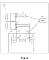
- FIG. 2 Other embodiments and/or aspects of this disclosure are shown in Fig. 2 .
- Certain embodiments described herein can be used to harvest waste energy from a powerplant for charging a battery and/or powering an electric motor.
- a system 100 can include a turbine 102 configured to fluidly connect to a heat engine 104 to be driven by exhaust from the heat engine 104, the turbine 102 including a turbine shaft 106.
- a generator 108 can be operatively coupled to the turbine shaft 106 to be driven by the turbine 102 and configured to receive rotational input power from turbine shaft 106 and to convert the rotational input power to output power to generate electrical energy.
- the electrical energy can be used to power an electric motor 110 (e.g., of a hybrid-electric powerplant 112 of an aircraft 1).
- the system can further include, the heat engine 104 configured to drive a heat engine shaft 116, the electric motor 110 configured to drive an electric motor shaft 118, and a transmission system 120 including at least one gearbox 122.
- the transmission system 120 can be configured to receive rotational input power from each of the heat engine shaft 116 and the electric motor shaft 118 and to convert the rotation input power to output power to generate thrust.
- the heat engine 104, the electric motor 110, and the transmission system 120 can together form at least part of the hybrid-electric powerplant 112.
- the heat engine 104 of the hybrid-electric powerplant 112 could be a heat engine of any type, e.g., a gas turbine, spark ignited, diesel, rotary or reciprocating engine of any fuel type and with any configuration of turbomachinery elements, either turbocharger, turbosupercharger, supercharger and exhaust recovery turbo compounding, either mechanically, electrically, hydraulically or pneumatically driven.
- a gas turbine spark ignited
- diesel diesel
- turbomachinery elements either turbocharger, turbosupercharger, supercharger and exhaust recovery turbo compounding, either mechanically, electrically, hydraulically or pneumatically driven.
- the at least one gearbox 122 can include a combining gearbox connecting to the heat engine shaft 116 and to the electric motor shaft 118 to combine rotational input power from the heat engine 104 and electric motor 110 for providing rotational output power to an output shaft (e.g., an engine shaft 124).
- the engine shaft 124 can be further connected to a second gearbox, or else to an air mover 126 (e.g., a fan or propeller) to generate thrust and propel the aircraft 1.
- Any suitable number of additional gearboxes can be included in the hybrid-electric propulsion system to drive any suitable number of air movers.
- the system 100 can further include an electric energy storage unit 128 (e.g., a battery) electrically connected to provide power to the electric motor 110.
- the electric energy storage unit 128 can be electrically connected between the generator 108 and the electric motor 110.
- the generator 108 can be configured to provide electrical energy to be stored in the electric energy storage unit 128 to charge the electric energy storage unit 128.
- the electric motor 110 does not contribute to charging the electric energy storage unit 128. The electric motor 110 instead is configured only to draw power from the electric energy storage unit 128.
- the turbine 102 can be directly driven by the exhaust 129 from the heat engine 104.
- the turbine 102 is not mechanically connected to any of the heat engine 104, the electric motor 110, the transmission system 120, or the engine shaft 124, and therefore is not driven mechanically by any portion of the hybrid-electric powerplant 112.
- the system 100 as described herein utilizes strictly waste exhaust from the heat engine 104 to generate electricity through the generator 108, rather than using "free" energy from rotation of the engine shaft 124 during normal operation or windmilling, for example.
- a system 200 can have similar components as in system 100.
- the system 200 can include a compressor 230 operatively coupled to the turbine shaft 206 configured to provide compressed air 232 to the heat engine 104 for combustion.
- the generator 208 can be operatively coupled to the turbine shaft 206 between the compressor 230 and the turbine 202.
- the compressor 230 and turbine 202 can form a turbocharger 234 for turbocharging the heat engine 104.
- a method can include directly driving a turbine (e.g., turbine 102, 202) with exhaust from an internal combustion engine (e.g., heat engine 104), extracting electrical power from rotation of the turbine, storing the electrical power in an electric energy storage unit (e.g., unit 128), and using the stored electrical power to drive an electric motor (e.g., motor 110) of a hybrid propulsion system (e.g., powerplant 112) to generate thrust.
- extracting electrical power includes extracting rotational power of the turbine with a turbocharger (e.g., turbocharger 234), wherein the turbine is a turbocharger turbine.
- the method can further include providing compressed air to the internal combustion engine with a compressor (e.g., compressor 230) of the turbocharger.
- Fuel burning engines generate waste heat due to engine cycle inefficiency.
- Certain internal combustion engines e.g., reciprocating, rotary, and the like
- a turbocharger to provide additional horsepower and/or altitude capability.
- Embodiments incorporate a generator that utilizes this exhaust energy (e.g., through a turbine either alone or as a part of the turbocharger unit) that can allow this otherwise wasted energy to be used for battery recharging, allowing incorporation of a smaller battery without engine fuel usage penalty.
- Embodiments allow for reduced aircraft weight due to smaller battery size for reduced fuel burn and carbon emissions.
- Embodiments also allow for increased aircraft safety due to ability to ability to recharge battery in flight without incurring aircraft range reduction.
- any numerical values disclosed herein can be exact values or can be values within a range. Further, any terms of approximation (e.g., “about”, “approximately”, “around”) used in this disclosure can mean the stated value within a range. For example, in certain embodiments, the range can be within (plus or minus) 20%, or within 10%, or within 5%, or within 2%, or within any other suitable percentage or number as appreciated by those having ordinary skill in the art (e.g., for known tolerance limits or error ranges).
- a reference to "A and/or B", when used in conjunction with open-ended language such as “comprising” can refer, in one embodiment, to A only (optionally including elements other than B); in another embodiment, to B only (optionally including elements other than A); in yet another embodiment, to both A and B (optionally including other elements); etc.
Landscapes
- Engineering & Computer Science (AREA)
- Mechanical Engineering (AREA)
- General Engineering & Computer Science (AREA)
- Chemical & Material Sciences (AREA)
- Combustion & Propulsion (AREA)
- Aviation & Aerospace Engineering (AREA)
- Supercharger (AREA)
Abstract
Description
- The present disclosure relates to parallel hybrid propulsion system, and more particularly to energy harvesting for the parallel hybrid propulsion system.
- Typical hybrid electrified powertrains include a battery to provide energy for certain portions of the mission. The mission may include electrical augmentation for use in aborted landing or go-around scenarios, for example. Reserve energy can be accommodated by sizing a battery to allow for charging on the ground prior to flight, or a smaller battery can be depleted/recharged multiple times over the course of a flight. However, charging the battery using a motor/generator on the vehicle in a conventional hybrid arrangement consumes fuel (and generates CO2) since the engine shaft energy is needed to drive the motor/generator. This can result is increased fuel consumption due to either excess battery weight or need to carry excess fuel for charging of a battery
- There is always a need in the art for improvements to energy harvesting, e.g., in the context of hybrid powertrains, including in the aerospace industry. This disclosure provides a solution for this need.
- In accordance with at least one aspect of this disclosure, a system includes a turbine configured to fluidly connect to a heat engine to be driven by exhaust from the heat engine, the turbine including a turbine shaft, and a generator operatively coupled to the turbine shaft to be driven by the turbine configured to receive rotational input power from turbine shaft and to convert the rotational input power to output power to generate electrical energy.
- In embodiments, the system can further include, the heat engine configured to drive a heat engine shaft, an electric motor configured to drive an electric motor shaft, and a transmission system including at least one gearbox, the transmission system configured to receive rotational input power from each of the heat engine shaft and the electric motor shaft and to convert the rotation input power to output power to generate thrust. In embodiments, the turbine is not mechanically connected to the transmission system.
- In embodiments, the system can further include an electric energy storage unit (e.g., a battery) electrically connected to provide power to the electric motor. In certain embodiments, the electric energy storage unit can be electrically connected between the generator and the electric motor. In such embodiments, the generator can be configured to provide electrical energy to be stored in the electric energy storage unit to charge the electric energy storage unit. In certain embodiments, the electric motor does not contribute to charging the electric energy storage unit.
- In embodiments, the turbine can be directly driven by the exhaust from the heat engine without any intervening mechanical, electrical, or pneumatic components between the heat engine and the turbine.
- In certain embodiments, the system can include a compressor operatively coupled to the turbine shaft configured to provide compressed air to the heat engine for combustion. The generator can be operatively coupled to the turbine shaft between the compressor and the turbine in such embodiments. In certain embodiments, the compressor and turbine can form a turbocharger for turbocharging the heat engine.
- In accordance with at least one aspect of this disclosure, an aircraft power system can include one or more auxiliary turbines configured to fluidly connect to an internal combustion engine to receive an exhaust flow from the internal combustion engine and convert energy of the exhaust flow into rotational power. A generator can be operatively connected to receive at least some of the rotational power from the turbine for generating electrical power, and at least one electric storage unit electrically can be connected to the generator to receive at least some of the electrical power to store the electrical power to be used by a hybrid propulsion system.
- In embodiments, the aircraft power system can include the hybrid propulsion system including the internal combustion engine and an electric motor, the electric motor being electrically connected to draw power from the electric energy storage unit.
- In embodiments, the turbine can include a turbine shaft, and in certain embodiments, a compressor for supplying combustion air to the internal combustion engine, the turbine shaft operatively connecting one of the one or more auxiliary turbines to the compressor to transfer at least some of the rotational power to the compressor.
- In accordance with at least one aspect of this disclosure, a method can include directly driving a turbine with exhaust from an internal combustion engine, extracting electrical power from rotation of the turbine, storing the electrical power in an electric energy storage unit, and using the stored electrical power to drive an electric motor of a hybrid propulsion system to generate thrust. In embodiments, extracting electrical power includes extracting rotational power of the turbine with a turbocharger, wherein the turbine is a turbocharger turbine. In embodiments, the method can further include providing compressed air to the internal combustion engine with a compressor of the turbocharger.
- These and other features of the embodiments of the subject disclosure will become more readily apparent to those skilled in the art from the following detailed description taken in conjunction with the drawings.
- So that those skilled in the art to which the subject disclosure appertains will readily understand how to make and use the devices and methods of the subject disclosure without undue experimentation, embodiments thereof will be described in detail herein below with reference to certain figures, wherein:
-
Fig. 1 is a schematic diagram of an embodiment of a system in accordance with this disclosure, showing an aircraft power system; and -
Fig. 2 is a schematic diagram of another embodiment of an aircraft power system. - Reference will now be made to the drawings wherein like reference numerals identify similar structural features or aspects of the subject disclosure. For purposes of explanation and illustration, and not limitation, an illustrative view of an embodiment of a system in accordance with the disclosure is shown in
Fig. 1 and is designated generally byreference character 100. Other embodiments and/or aspects of this disclosure are shown inFig. 2 . Certain embodiments described herein can be used to harvest waste energy from a powerplant for charging a battery and/or powering an electric motor. - In accordance with at least one aspect of this disclosure, a system 100 (e.g., an aircraft power system) can include a
turbine 102 configured to fluidly connect to aheat engine 104 to be driven by exhaust from theheat engine 104, theturbine 102 including aturbine shaft 106. Agenerator 108 can be operatively coupled to theturbine shaft 106 to be driven by theturbine 102 and configured to receive rotational input power fromturbine shaft 106 and to convert the rotational input power to output power to generate electrical energy. In embodiments, the electrical energy can be used to power an electric motor 110 (e.g., of a hybrid-electric powerplant 112 of an aircraft 1). - The system can further include, the
heat engine 104 configured to drive aheat engine shaft 116, theelectric motor 110 configured to drive anelectric motor shaft 118, and atransmission system 120 including at least onegearbox 122. Thetransmission system 120 can be configured to receive rotational input power from each of theheat engine shaft 116 and theelectric motor shaft 118 and to convert the rotation input power to output power to generate thrust. Theheat engine 104, theelectric motor 110, and thetransmission system 120 can together form at least part of the hybrid-electric powerplant 112. - It is envisioned that the
heat engine 104 of the hybrid-electric powerplant 112 could be a heat engine of any type, e.g., a gas turbine, spark ignited, diesel, rotary or reciprocating engine of any fuel type and with any configuration of turbomachinery elements, either turbocharger, turbosupercharger, supercharger and exhaust recovery turbo compounding, either mechanically, electrically, hydraulically or pneumatically driven. - The at least one
gearbox 122 can include a combining gearbox connecting to theheat engine shaft 116 and to theelectric motor shaft 118 to combine rotational input power from theheat engine 104 andelectric motor 110 for providing rotational output power to an output shaft (e.g., an engine shaft 124). Theengine shaft 124 can be further connected to a second gearbox, or else to an air mover 126 (e.g., a fan or propeller) to generate thrust and propel theaircraft 1. Any suitable number of additional gearboxes can be included in the hybrid-electric propulsion system to drive any suitable number of air movers. - In embodiments, the
system 100 can further include an electric energy storage unit 128 (e.g., a battery) electrically connected to provide power to theelectric motor 110. In certain embodiments, the electricenergy storage unit 128 can be electrically connected between thegenerator 108 and theelectric motor 110. In such embodiments, thegenerator 108 can be configured to provide electrical energy to be stored in the electricenergy storage unit 128 to charge the electricenergy storage unit 128. In certain embodiments, theelectric motor 110 does not contribute to charging the electricenergy storage unit 128. Theelectric motor 110 instead is configured only to draw power from the electricenergy storage unit 128. - In embodiments, the
turbine 102 can be directly driven by theexhaust 129 from theheat engine 104. For example, there is no intervening mechanical, electrical, or pneumatic components between theheat engine 104 and theturbine 102. Further, in embodiments theturbine 102 is not mechanically connected to any of theheat engine 104, theelectric motor 110, thetransmission system 120, or theengine shaft 124, and therefore is not driven mechanically by any portion of the hybrid-electric powerplant 112. Thesystem 100 as described herein utilizes strictly waste exhaust from theheat engine 104 to generate electricity through thegenerator 108, rather than using "free" energy from rotation of theengine shaft 124 during normal operation or windmilling, for example. - In certain embodiments, a
system 200 can have similar components as insystem 100. For brevity, the description of common elements that have been described above are not repeated with respect toFig. 2 . Thesystem 200 can include acompressor 230 operatively coupled to theturbine shaft 206 configured to providecompressed air 232 to theheat engine 104 for combustion. Here, thegenerator 208 can be operatively coupled to theturbine shaft 206 between thecompressor 230 and theturbine 202. In this case, thecompressor 230 andturbine 202 can form aturbocharger 234 for turbocharging theheat engine 104. - In accordance with at least one aspect of this disclosure, a method can include directly driving a turbine (e.g.,
turbine 102, 202) with exhaust from an internal combustion engine (e.g., heat engine 104), extracting electrical power from rotation of the turbine, storing the electrical power in an electric energy storage unit (e.g., unit 128), and using the stored electrical power to drive an electric motor (e.g., motor 110) of a hybrid propulsion system (e.g., powerplant 112) to generate thrust. In embodiments, extracting electrical power includes extracting rotational power of the turbine with a turbocharger (e.g., turbocharger 234), wherein the turbine is a turbocharger turbine. In embodiments, the method can further include providing compressed air to the internal combustion engine with a compressor (e.g., compressor 230) of the turbocharger. - Fuel burning engines generate waste heat due to engine cycle inefficiency. Certain internal combustion engines (e.g., reciprocating, rotary, and the like) often include a turbocharger to provide additional horsepower and/or altitude capability. Embodiments incorporate a generator that utilizes this exhaust energy (e.g., through a turbine either alone or as a part of the turbocharger unit) that can allow this otherwise wasted energy to be used for battery recharging, allowing incorporation of a smaller battery without engine fuel usage penalty. Embodiments allow for reduced aircraft weight due to smaller battery size for reduced fuel burn and carbon emissions. Embodiments also allow for increased aircraft safety due to ability to ability to recharge battery in flight without incurring aircraft range reduction.
- Those having ordinary skill in the art understand that any numerical values disclosed herein can be exact values or can be values within a range. Further, any terms of approximation (e.g., "about", "approximately", "around") used in this disclosure can mean the stated value within a range. For example, in certain embodiments, the range can be within (plus or minus) 20%, or within 10%, or within 5%, or within 2%, or within any other suitable percentage or number as appreciated by those having ordinary skill in the art (e.g., for known tolerance limits or error ranges).
- The articles "a", "an", and "the" as used herein and in the appended claims are used herein to refer to one or to more than one (i.e., to at least one) of the grammatical object of the article unless the context clearly indicates otherwise. By way of example, "an element" means one element or more than one element.
- The phrase "and/or," as used herein in the specification and in the claims, should be understood to mean "either or both" of the elements so conjoined, i.e., elements that are conjunctively present in some cases and disjunctively present in other cases. Multiple elements listed with "and/or" should be construed in the same fashion, i.e., "one or more" of the elements so conjoined. Other elements may optionally be present other than the elements specifically identified by the "and/or" clause, whether related or unrelated to those elements specifically identified. Thus, as a non-limiting example, a reference to "A and/or B", when used in conjunction with open-ended language such as "comprising" can refer, in one embodiment, to A only (optionally including elements other than B); in another embodiment, to B only (optionally including elements other than A); in yet another embodiment, to both A and B (optionally including other elements); etc.
- As used herein in the specification and in the claims, "or" should be understood to have the same meaning as "and/or" as defined above. For example, when separating items in a list, "or" or "and/or" shall be interpreted as being inclusive, i.e., the inclusion of at least one, but also including more than one, of a number or list of elements, and, optionally, additional unlisted items. Only terms clearly indicated to the contrary, such as "only one of" or "exactly one of," or, when used in the claims, "consisting of," will refer to the inclusion of exactly one element of a number or list of elements. In general, the term "or" as used herein shall only be interpreted as indicating exclusive alternatives (i.e., "one or the other but not both") when preceded by terms of exclusivity, such as "either," "one of," "only one of," or "exactly one of "
- Any suitable combination(s) of any disclosed embodiments and/or any suitable portion(s) thereof are contemplated herein as appreciated by those having ordinary skill in the art in view of this disclosure.
- The embodiments of the present disclosure, as described above and shown in the drawings, provide for improvement in the art to which they pertain. While the apparatus and methods of the subject disclosure have been shown and described, those skilled in the art will readily appreciate that changes and/or modifications may be made thereto without departing from the scope of the subject disclosure.
Claims (15)
- A system (100), comprising:a turbine (102) configured to fluidly connect to a heat engine (104) to be driven by exhaust from the heat engine, the turbine including a turbine shaft (106); anda generator (108) operatively coupled to the turbine shaft (106) to be driven by the turbine (102) configured to receive rotational input power from turbine shaft (106) and to convert the rotational input power to output power to generate electrical energy.
- The system of claim 1, further comprising:the heat engine (104) configured to drive a heat engine shaft (116);an electric motor (110) configured to drive an electric motor shaft (118); anda transmission system (120) including at least one gearbox (122), wherein the transmission system (120) is configured to receive rotational input power from each of the heat engine shaft (116) and the electric motor shaft (118) and to convert the rotation input power to output power to generate thrust.
- The system of claim 2, further comprising an electric energy storage unit (128) electrically connected to provide power to the electric motor (110).
- The system of claim 3, wherein the electric energy storage unit (128) is electrically connected between the generator (108) and the electric motor (110).
- The system of claim 4, wherein the generator (108) is configured to provide electrical energy to be stored in the electric energy storage unit (128) to charge the electric energy storage unit (128).
- The system of claim 5, wherein the electric motor (110) does not contribute to charging the electric energy storage unit (128).
- The system of claim 2, wherein the turbine (102) is directly driven by the exhaust from the heat engine without any intervening mechanical, electrical, or pneumatic components between the heat engine (104) and the turbine (102).
- The system of claim 2, further comprising a compressor (230) operatively coupled to the turbine shaft (206) configured to provide compressed air to the heat engine (104) for combustion.
- The system of claim 8, wherein the generator (108) is operatively coupled to the turbine shaft (206) between the compressor (230) and the turbine (102).
- The system of claim 8, wherein the compressor (230) and turbine (102) form a turbocharger.
- The system of claim 2, wherein the turbine (102) is not mechanically connected to the transmission system (120).
- The system of any preceding claim, wherein the electric energy storage unit (128) includes a battery.
- A method comprising:directly driving a turbine with exhaust from an internal combustion engine;extracting electrical power from rotation of the turbine;storing the electrical power in an electric energy storage unit; andusing the stored electrical power to drive an electric motor of a hybrid propulsion system to generate thrust.
- The method of claim 13, wherein extracting electrical power includes extracting rotational power of the turbine with a turbocharger, wherein the turbine is a turbocharger turbine.
- The method of claim 14, further comprising providing compressed air to the internal combustion engine with a compressor of the turbocharger.
Applications Claiming Priority (1)
| Application Number | Priority Date | Filing Date | Title |
|---|---|---|---|
| US17/942,945 US11802489B1 (en) | 2022-09-12 | 2022-09-12 | Energy harvesting for hybrid propulsion systems |
Publications (1)
| Publication Number | Publication Date |
|---|---|
| EP4336034A1 true EP4336034A1 (en) | 2024-03-13 |
Family
ID=88017900
Family Applications (1)
| Application Number | Title | Priority Date | Filing Date |
|---|---|---|---|
| EP23196979.1A Pending EP4336034A1 (en) | 2022-09-12 | 2023-09-12 | Energy harvesting for hybrid propulsion systems |
Country Status (2)
| Country | Link |
|---|---|
| US (1) | US11802489B1 (en) |
| EP (1) | EP4336034A1 (en) |
Families Citing this family (3)
| Publication number | Priority date | Publication date | Assignee | Title |
|---|---|---|---|---|
| US12576979B2 (en) | 2024-02-29 | 2026-03-17 | Pratt & Whitney Canada Corp. | Aircraft propulsion system with engine assembly, intercooler, and turbocompressor assembly |
| US12215908B1 (en) * | 2024-02-29 | 2025-02-04 | Thevu LLC | Air conditioning system and transportation system including same |
| US12405035B1 (en) | 2024-02-29 | 2025-09-02 | Thevu LLC | Air conditioning system and transportation system including same |
Citations (4)
| Publication number | Priority date | Publication date | Assignee | Title |
|---|---|---|---|---|
| US20160167799A1 (en) * | 2014-12-16 | 2016-06-16 | Airbus Group Sas | Method of managing a power demand for the operation of a pilotless aircraft equipped with an internal combustion engine |
| US20170029131A1 (en) * | 2015-07-29 | 2017-02-02 | Airbus Defence and Space GmbH | Hybrid Electric Drive Train For VTOL Drones |
| US20200173354A1 (en) * | 2018-11-29 | 2020-06-04 | Deere & Company | Electrified air system for removing cold start aids |
| US20210309351A1 (en) * | 2020-04-07 | 2021-10-07 | Aurora Flight Sciences Corporation, a subsidiary of The Boeing Company | Aircraft having hybrid propulsion |
Family Cites Families (4)
| Publication number | Priority date | Publication date | Assignee | Title |
|---|---|---|---|---|
| IT201700004557A1 (en) * | 2017-01-17 | 2018-07-17 | Ferrari Spa | METHOD OF CONTROL OF A TURBOCHARGER PROVIDED WITH ELECTRIC IMPLEMENTATION IN AN OVERALLY OVER-COMBUSTION INTERNAL COMBUSTION ENGINE |
| CN107696812B (en) | 2017-10-10 | 2019-06-28 | 中国人民解放军国防科技大学 | Oil-electricity hybrid power system and vertical take-off and landing hovercar with same |
| DE102018109010B4 (en) * | 2018-04-17 | 2025-02-20 | Man Energy Solutions Se | Charging device for an internal combustion engine and system comprising an internal combustion engine and the charging device |
| US20200039657A1 (en) | 2018-08-02 | 2020-02-06 | Southwest Research Institute | Variable Cycle Hybrid Power and Propulsion System for Aircraft |
-
2022
- 2022-09-12 US US17/942,945 patent/US11802489B1/en active Active
-
2023
- 2023-09-12 EP EP23196979.1A patent/EP4336034A1/en active Pending
Patent Citations (4)
| Publication number | Priority date | Publication date | Assignee | Title |
|---|---|---|---|---|
| US20160167799A1 (en) * | 2014-12-16 | 2016-06-16 | Airbus Group Sas | Method of managing a power demand for the operation of a pilotless aircraft equipped with an internal combustion engine |
| US20170029131A1 (en) * | 2015-07-29 | 2017-02-02 | Airbus Defence and Space GmbH | Hybrid Electric Drive Train For VTOL Drones |
| US20200173354A1 (en) * | 2018-11-29 | 2020-06-04 | Deere & Company | Electrified air system for removing cold start aids |
| US20210309351A1 (en) * | 2020-04-07 | 2021-10-07 | Aurora Flight Sciences Corporation, a subsidiary of The Boeing Company | Aircraft having hybrid propulsion |
Also Published As
| Publication number | Publication date |
|---|---|
| US11802489B1 (en) | 2023-10-31 |
Similar Documents
| Publication | Publication Date | Title |
|---|---|---|
| EP4336034A1 (en) | Energy harvesting for hybrid propulsion systems | |
| US20230137264A1 (en) | Architectures for hybrid-electric propulsion | |
| US10371066B2 (en) | Unmanned aircraft and operation method for the same | |
| EP3569498B1 (en) | Hybrid aircraft propulsion system | |
| US10837304B2 (en) | Hybrid-electric drive system | |
| US10408133B2 (en) | Accessory drive system for a gas turbine engine | |
| US11667391B2 (en) | Dual engine hybrid-electric aircraft | |
| US20200039657A1 (en) | Variable Cycle Hybrid Power and Propulsion System for Aircraft | |
| US9601970B2 (en) | Gas turbine engine and electrical system | |
| US8432048B1 (en) | Hybrid engine with a gas turbine engine | |
| EP3736423A1 (en) | Hybrid electric aircraft propulsion system | |
| US20160257416A1 (en) | Propulsion system | |
| EP2631182A2 (en) | An auxiliary power system | |
| KR20130087389A (en) | Method and architecture for recombining the power of a turbomachine | |
| US12145734B2 (en) | Hybrid propulsion systems | |
| US11286054B2 (en) | Dual hybrid propulsion system for an aircraft having a cross-connecting clutch | |
| EP4198286A2 (en) | Restarting a gas turbine engine | |
| US20240243632A1 (en) | Electrical energy system having different axial lengths for efficient power generation | |
| CN103912349A (en) | Engine power turbine energy recovery device | |
| EP3831720B1 (en) | Aircraft propulsion system and methods of feathering | |
| CN119173685A (en) | Improved turbine for hybrid aircraft | |
| US12595746B2 (en) | Aircraft propulsion system with clocked electric machine and accessory gearbox | |
| CN221942567U (en) | Built-in turbine engine |
Legal Events
| Date | Code | Title | Description |
|---|---|---|---|
| PUAI | Public reference made under article 153(3) epc to a published international application that has entered the european phase |
Free format text: ORIGINAL CODE: 0009012 |
|
| STAA | Information on the status of an ep patent application or granted ep patent |
Free format text: STATUS: THE APPLICATION HAS BEEN PUBLISHED |
|
| AK | Designated contracting states |
Kind code of ref document: A1 Designated state(s): AL AT BE BG CH CY CZ DE DK EE ES FI FR GB GR HR HU IE IS IT LI LT LU LV MC ME MK MT NL NO PL PT RO RS SE SI SK SM TR |
|
| STAA | Information on the status of an ep patent application or granted ep patent |
Free format text: STATUS: REQUEST FOR EXAMINATION WAS MADE |
|
| 17P | Request for examination filed |
Effective date: 20240902 |
|
| RBV | Designated contracting states (corrected) |
Designated state(s): AL AT BE BG CH CY CZ DE DK EE ES FI FR GB GR HR HU IE IS IT LI LT LU LV MC ME MK MT NL NO PL PT RO RS SE SI SK SM TR |
|
| STAA | Information on the status of an ep patent application or granted ep patent |
Free format text: STATUS: EXAMINATION IS IN PROGRESS |
|
| 17Q | First examination report despatched |
Effective date: 20250417 |