EP4336013A1 - Connecting device and tool - Google Patents
Connecting device and tool Download PDFInfo
- Publication number
- EP4336013A1 EP4336013A1 EP23196352.1A EP23196352A EP4336013A1 EP 4336013 A1 EP4336013 A1 EP 4336013A1 EP 23196352 A EP23196352 A EP 23196352A EP 4336013 A1 EP4336013 A1 EP 4336013A1
- Authority
- EP
- European Patent Office
- Prior art keywords
- latch
- tool
- connector
- inner cavity
- drive
- Prior art date
- Legal status (The legal status is an assumption and is not a legal conclusion. Google has not performed a legal analysis and makes no representation as to the accuracy of the status listed.)
- Pending
Links
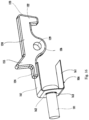
Images






Classifications
-
- B—PERFORMING OPERATIONS; TRANSPORTING
- B25—HAND TOOLS; PORTABLE POWER-DRIVEN TOOLS; MANIPULATORS
- B25D—PERCUSSIVE TOOLS
- B25D17/00—Details of, or accessories for, portable power-driven percussive tools
- B25D17/005—Attachments or adapters placed between tool and hammer
-
- E—FIXED CONSTRUCTIONS
- E21—EARTH OR ROCK DRILLING; MINING
- E21B—EARTH OR ROCK DRILLING; OBTAINING OIL, GAS, WATER, SOLUBLE OR MELTABLE MATERIALS OR A SLURRY OF MINERALS FROM WELLS
- E21B7/00—Special methods or apparatus for drilling
- E21B7/02—Drilling rigs characterised by means for land transport with their own drive, e.g. skid mounting or wheel mounting
- E21B7/027—Drills for drilling shallow holes, e.g. for taking soil samples or for drilling postholes
- E21B7/028—Drills for drilling shallow holes, e.g. for taking soil samples or for drilling postholes the drilling apparatus being detachable from the vehicle, e.g. hand portable drills
Definitions
- the present invention relates to the field of tools, and in particular to a connecting device and a tool comprising the connecting device.
- Tools are configured to receive tool heads, for example, pneumatic or electric augers, drill bits, and machine tools.
- Various tools are configured for specific tasks and may comprise a power unit configured for specific purposes, for example, powering an auger attachment or drill bit.
- a power unit configured for specific purposes, for example, powering an auger attachment or drill bit.
- engaging different tool heads with different power units may create operational, performance or safety risks to the tool or the user.
- the combination of a tool head and a power unit may result in unreliable or insufficient coupling of the power or torque provided by the power unit.
- the present invention provides a structure and a method for connecting a tool head to a power unit. More specifically, the structure and the method for connecting a tool head to a power unit are advantageous in that the structure and the method can establish a secure connection of a tool head to the tool, mitigate incomplete or unreliable mechanical connection between the tool head and the tool, or reduce operational, performance and safety risks associated with the connection between the tool head and the tool.
- the present invention provides a connecting device used for connecting a tool.
- a longitudinal direction, a transverse direction and a vertical direction perpendicular to each other are defined for the connecting device, and a first end and a second end spaced apart are provided in the longitudinal direction.
- the connecting device comprises: a connector, which has an inner cavity extending in the longitudinal direction, a tool end opening connected to the inner cavity and a latch opening connected to the inner cavity, wherein the tool end opening is configured to allow a drive shaft of a tool head to pass through it into the inner cavity in the longitudinal direction; a latch, which is located in the inner cavity and is capable of moving between a locked position and an unlocked position, the latch comprising an engaging portion, which is configured to engage with a corresponding mating portion on the drive shaft entering the inner cavity in the locked position and is disengaged from the mating portion in the unlocked position; and a drive part, which is provided on the connector and is capable of being driven on the latch opening along the longitudinal direction to drive the latch to move.
- the latch is located in the inner cavity and is capable of moving between the locked position and the unlocked position and the drive part is provided on the connector and is capable of being driven on the latch opening along the longitudinal direction to drive the latch to move, thus the connector can be connected to the output shaft of a tool
- the engaging portion is configured to engage with the corresponding mating portion on the drive shaft entering the inner cavity in the locked position, and the engaging portion is disengaged from the mating portion in the unlocked position, and therefore, through this mating relationship between the latch and the drive part, in the locked position, the latch of the inner cavity can lock the drive shaft of the tool head extending into the inner cavity, to securely connect the connector and the tool head, and in the unlocked position, the latch unlocks the drive shaft, to allow the drive shaft to be taken out from the inner cavity. Therefore, it can establish a secure connection of the tool head to the tool, mitigate incomplete or unreliable mechanical connection between the tool head and the tool, and reduce operational, performance and safety risks associated with the connection between the tool head and the tool.
- the connector is formed with a first opening extending along the transverse direction
- the latch is formed with a second opening extending along the transverse direction, wherein the latch is connected to the connector by use of a pivot that passes through the first opening and the second opening.
- the latch is pivotably provided on the connector to allow the latch to move in the vertical direction.
- the latch comprises a stop end extending toward the second end along the longitudinal direction and a connecting portion located between the stop end and the engaging portion, and an accommodating space for accommodating a drive shaft end of the drive shaft is formed between the connecting portion and the engaging portion.
- the connecting portion comprises a first inclined surface, and the first inclined surface is configured to be capable of contacting a drive inclined surface of the drive shaft end.
- the engaging portion is formed with a second inclined surface, and the second inclined surface is configured to be in sliding contact with the drive inclined surface of the drive shaft end of the drive shaft when the drive shaft extends into the inner cavity.
- the connecting device further comprises a first elastic part, the first elastic part is arranged between the drive part and a stop portion of the connector to store energy when the drive part is driven, the first elastic part, when releasing energy, is capable of biasing the drive part to an initial position, and, in the initial position, the drive part keeps the latch in the locked position.
- the connecting device further comprises a pivotably arranged actuating part, and the pivot axis of the actuating part extends along the transverse direction, wherein, the actuating part is capable of driving the drive part to move from the initial position to a released position under an action of an external force applied by an operator; when in the initial position, the drive part keeps the latch in the locked position, and when in the released position, the drive part allows the latch to be in the unlocked position.
- the actuating part comprises an open mouth
- the connector extends through the open mouth, wherein at least two opposite edges of the open mouth contact the drive part.
- contact protrusions in contact with the drive part are respectively formed on the at least two opposite mouth edges.
- the actuating part is an actuating plate.
- the actuating part is an elastic actuating part.
- the latch comprises a latch protrusion, and, when the actuating part drives the drive part to move from the initial position to the released position, the drive part drives the latch protrusion to drive the latch to move from the locked position to the unlocked position.
- a second elastic part acting on the latch is provided in the inner cavity, wherein, the second elastic part stores energy when the latch moves from the locked position to the unlocked position, wherein the second elastic part, when releasing energy, biases the latch to the locked position.
- a connector power input end of the connector has a connecting part, and the connecting part is configured to securely connect the connector power input end to an upstream power output end, wherein a part of the second elastic part serves as a connecting gasket of the connecting part.
- the second elastic part is a U-shaped elastic piece
- one elastic side wall of the U-shaped elastic piece acts on the stop end of the latch
- another elastic side wall of the U-shaped elastic piece is used as a supporting side wall
- a bottom wall of the U-shaped elastic piece is used as the connecting gasket, wherein, a mounting hole is formed on the bottom wall, and the connecting part passes through the mounting hole and extends toward the second end along the longitudinal direction in the inner cavity.
- an accommodating channel is formed on an end surface of the connector power input end, the accommodating channel is configured to accommodate a power output shaft upstream of power transmission, a through hole is formed on a spacer side wall between the accommodating channel and the inner cavity, and the connecting part extends from the inner cavity through the through hole into the accommodating channel to connect to the power output shaft, so that the connector and the power output shaft are connected to each other.
- the actuating part is configured to protrude from the actuator opening on the housing of the tool; or, the actuating part is configured to engage with a drive button movably arranged on the housing of the tool, and the actuating part is capable of pivoting under the drive of the drive button.
- the present invention provides a tool, which comprises: a power unit, which outputs power through a power output shaft; and the connecting device described in any paragraph in the first aspect above; wherein the power output shaft and the connector are connected in a power transmitting manner.
- the tool further comprises a detachably installed battery unit, and the battery unit provides driving power to a driving motor of the power unit.
- the tool further comprises a tool head, and a drive shaft of the tool head passes through the tool end opening into the inner cavity in the longitudinal direction, wherein, the mating portion of the drive shaft engages with the engaging portion in the locked position, and the engaging portion is disengaged from the mating portion in the unlocked position.
- the tool head is an auger bit.
- the tool further comprises a housing, an actuator opening is formed on the housing, and an actuating part protrudes from the actuator opening; or, a movable drive button is provided on the housing, the actuating part engages with the drive button, and the actuating part is capable of pivoting under the drive of the drive button.
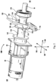
- Figure 1 provides an exemplary embodiment of the tool assembly 10 having a tool head 20.
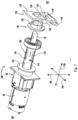
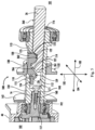
- Figures 2 to 6 provide an exemplary embodiment of the connecting device 100.
- the connecting device 100 is configured to operatively connect the tool head 20 (for example, an auger attachment, drill bit or other mechanical drill bit) to the tool 10.
- the tool head 20 comprises a shank or shaft 22 extending along the longitudinal direction 101.
- the tool surface 24 (for example, a blade, groove or another tool component) extends from the shaft 22.
- the tool head 20 may be formed as an auger attachment.
- the tool assembly 10 may comprise a power unit 12, and the power unit 12 is configured to output power or torque to the tool head 20.
- the tool assembly 10 may generally comprise a handle 14, and a user can hold the handle 14 and operate and control the tool assembly 10.
- the attachment connection 15 is formed where the tool assembly 10 and the tool head 20 are connected to each other.
- the connecting device 100 is formed or positioned at the attachment connection 15, and the tool head 20 and the tool assembly 10 are operably connected to each other at the attachment connection 15.
- the extension of the referenced longitudinal direction 103 coincides with the extension of the tool head 20, in particular with the extension of the shaft 22 of the tool head 20.
- the longitudinal direction 103 may form the axis along which the shaft 22 or the connector (for example, a connecting shaft) 110 extends.
- the first end 101 forms the tool end
- the tool head 20 is configured at this tool end to contact a surface, object, structure or another working surface (for example, a field into which an auger may penetrate).
- the tool head 20 is configured to receive power or torque from the power unit 12, and the power unit 12 may comprise, for example, an electric motor for driving the tool head and a power source such as a battery or a gas engine.
- the second end 102 forms an operating end, a user can hold and operate the tool assembly 10 at this end.
- the vertical direction 105 and the transverse direction 104 are respectively perpendicular to the longitudinal direction 103. Therefore, the longitudinal direction 103, the transverse direction 104 and the vertical direction 105 are perpendicular to each other.
- the vertical direction 105 and the transverse direction 104 respectively extend through the connector 110 from a centreline formed by the longitudinal direction 103.
- the radial direction may essentially extend from the centreline through the connector 110.
- the connecting device 100 comprises a connector or connector shaft 110 releasably connected to the output shaft 16 of the tool assembly 10.
- the drive shaft 26 is releasably connected to the connector 110.
- the drive shaft 26 forms part of the tool head 20.
- the drive shaft 26 forms a shaft extending from the shank or shaft 22, and the tool surface 24 is formed or extends at the shank or shaft 22.
- the connector 110 extends along the longitudinal axis 103.
- the connector 110 is formed with an inner cavity 112 extending along the longitudinal direction 103.
- the inner cavity 112 formed in the connector 110 is capable of allowing the drive shaft 26 to extend into the inner cavity 112 along the longitudinal direction 103.
- the inner cavity 112 formed in the connector 110 is capable of allowing the drive shaft 26 to extend into the inner cavity 112 from the first end 101 toward the second end 102 along the longitudinal direction 103.
- the connector 110 comprises a body 114 extending along the longitudinal direction 103.
- the body 114 forms an essentially cylindrical body extending along the longitudinal direction 103. It should be understood that the body 114 may comprise walls, depressions, grooves or surfaces extending from the body 114.
- the tool end opening 116 is formed close to the first end 101 and is configured to receive the drive shaft 26 along the longitudinal direction 103.
- the connector 110 is formed with a latch opening 118 to provide access to the inner cavity 112 along the vertical direction 105.
- the latch opening 118 allows the latch 120 to be inserted through the connector 110 into the inner cavity 112.
- the latch opening 118 is formed to pass through the longitudinal extension of the body 114.
- the latch opening 118 extends along the longitudinal direction 103 to form a longitudinally extending slot into the inner cavity 112.
- the latch 120 forms a member extending in the longitudinal direction 103.
- the latch 120 is configured to be positioned into the inner cavity 112 through the latch opening 118.
- the latch 120 comprises an engaging portion 122 extending in the vertical direction, for example, an engaging protrusion.
- the engaging portion 122 extends from the first latch end 125 along the vertical direction 105, and the first latch end 125 is close to the first end 101 in the longitudinal direction 103.
- the latch 120 may further form a second latch end or stop end 124 close to the second end 102 in the longitudinal direction.
- the latch 120 is formed with a stop end 124 extending in the inner cavity 112 inwardly from the second connector end 115 along the vertical direction 105.
- the second connector end 115 forms a part of the connector 110 along the longitudinal direction 103 and is arranged close to the second end 102 from the latch opening 118.
- the first connector end 113 forms a part of the connector 110 along the longitudinal direction 103 and is arranged close to the first end 101 from the latch opening 118.
- the engaging portion 122 is positioned close to the first connector end 113 along the longitudinal direction 103. It should be understood that the first latch end 125 is closer to the first end 101 than the second latch end or stop end 124 is. Additionally, the second latch end or stop end 124 is closer to the second end 102 than the first latch end 125 is.
- the latch 120 in various embodiments may comprise a connecting portion 126, for example, an arm, and the connecting portion 126 extends at least partially along the vertical direction 105.
- the connecting portion 126 may form a transition portion of the latch 120 between the engaging portion 122 and the stop end 124.
- the connecting portion 126 extends along the vertical direction 105 and positions the stop end 124 in the cavity 112 inside the second connector end 115 along the vertical direction 105.
- the drive shaft 26 is formed with a mating portion 262, for example, a groove.
- the mating portion 262 is configured to engage with the engaging portion 122 of the latch 122.
- a groove is configured to receive an engaging protrusion of the latch 122.
- the mating portion 262, for example, a groove extends substantially from the outer surface 260 along the vertical direction 105.
- the drive shaft 26 may be formed with a drive shaft second end or drive shaft end 261.
- the drive shaft end 261 is formed with a drive inclined surface 266 extending at least partially along the vertical direction 105.
- the drive shaft second end or drive shaft end 261 substantially corresponds to the accommodating space between the connecting portion 126 and the engaging portion 122 of the latch 120.
- the drive inclined surface 266 substantially corresponds to the first inclined surface 127 of the connecting portion 126.
- the connecting portion 126 comprises a first inclined surface 127 facing the first end, and the first inclined surface 127 is configured to be capable of contacting the drive inclined surface 266 of the drive shaft end 261.
- the first inclined surface 127 and the drive inclined surface 266 extend at an acute angle respectively along the vertical direction 105 and longitudinal direction 103.
- the drive inclined surface 266 may be positioned between the engaging portion 122 and the connecting portion 126 along the longitudinal direction 103.
- a groove formed in the drive shaft 26 is configured to receive the engaging portion 122 of the latch 122 when the drive shaft 26 extends into the inner cavity 112. In the inner cavity 112, the engagement between the engaging portion 122 and the mating portion 262, for example, an engaging protrusion positioned in a groove, limits the movement of the drive shaft 26 along the longitudinal direction 103.
- the connector 110 may be formed with a first opening 119 extending in the transverse direction 104.
- the latch 120 may be formed with a second opening 129 extending in the transverse direction 104.
- the first opening 119 and the second opening 129 are configured to correspond to each other to be aligned along the longitudinal direction 103.
- the first opening 119 and the second opening 129 when aligned along the longitudinal direction 103, may allow a shaft, pin, rod, shank, fastener or another member to extend through the first opening 119 and the second opening 129.
- the first opening 119 and the second opening 129 may allow the latch 120 to pivot in the inner cavity 112.
- a member extending through the first opening 119 and the second opening 129 may allow the latch 120 to pivot at the second opening 129 to selectively connect the engaging portion 122 along the vertical direction 105.
- the second opening 129 is positioned between the stop end 124 and the engaging portion 122 along the longitudinal direction 103.
- the second opening 129 is positioned on the connecting portion 126, or at the end of the connecting portion 126, to allow the latch 120 to pivot at the second opening 129.
- the drive part 130 may extend around the connector 110.
- the drive part 130 may extend circumferentially around the connector 110.
- the drive part 130 may move along the longitudinal direction 130 to selectively lock the latch 120.
- a sleeve may move along the longitudinal direction 130 to selectively encircle the latch 120.
- the drive part 130 can keep the drive shaft 26 in the connector 110 when locking the latch 120 (for example, when a sleeve encircles the latch 120).
- a sleeve encircling the latch 120 may retain or constrain an engaging protrusion on the latch 120 in a groove of the drive shaft 26.
- the engaging protrusion when in the groove, can retain the drive shaft 26 in the inner cavity 112 and limit or prevent the movement of the drive shaft 26 in the longitudinal direction 103.
- the engaging portion 122 is formed with a second inclined surface 123, and the second inclined surface 123 is configured to be in sliding contact with the drive inclined surface 266 of the drive shaft end 261 of the drive shaft 26 when the drive shaft 26 extends into the inner cavity 112.
- the drive inclined surface 266 will come into contact with the second inclined surface 123, and as the drive shaft 26 moves toward the first end 101, the second inclined surface 123 and the drive inclined surface 266 are in sliding contact, to drive the latch to pivot upward, thus making it easier for the latch to pivot.
- the motor 30 is configured to output energy to rotate the connector 110.
- the transmission assembly 40 is operatively connected between the motor 30 and the connector 110.
- the transmission assembly 40 may be configured to receive energy from the motor 30 and convert that energy into torque that can rotate the connector 110.
- the motor 30 may comprise any suitable power unit configured to output energy to rotate the output shaft 16.
- the transmission assembly 40 may comprise any suitable type of torque converter, which may comprise one or more gear sets and is configured to receive energy from the motor 30 and output power and torque through the connector 110.
- the power unit 12 of the tool assembly 10 comprises a motor 30 and a transmission assembly 40.
- the power unit 12 may comprise a manually actuated power unit configured to transmit power from a user to the tool head.
- the transmission assembly 40 may comprise an output shaft 16, and torque and power are transmitted from the output shaft 16 to the connector 110.
- the output shaft 16 comprises a threaded connection 160
- the threaded connection 160 is configured to receive a mechanical fastener, for example, a connecting part 191 (for example, typically a threaded shank and head, screw, bolt, tie rod, etc. The mechanical fastener is omitted for clarity).
- the threaded connection 160 extends along the longitudinal direction 103.
- the connector 110 may comprise a spacer side wall 111 extending along the vertical direction 105 in the inner cavity 112.
- the connector 110 is formed with an output shaft opening 117, and the output shaft 117 is close to the second end 102 in the longitudinal direction 103 (i.e., away from the tool end opening 116 that is close to the first end 101 in the longitudinal direction 103).
- the output shaft opening 117 allows the output shaft 16 to enter the inner cavity 112 along the longitudinal direction 103.
- the spacer side wall 111 is positioned between the output shaft opening 117 and the tool end opening 116 to allow the output shaft 16 to enter the inner cavity 112.
- the output shaft 16 can in particular extend along the longitudinal direction 103 and adjoin the spacer side wall 111 inside the inner cavity 112.
- a mechanical fastener can enter the inner cavity 112 through the tool end opening 116.
- the threaded end of the mechanical fastener can extend through the spacer side wall 111 and engage with the threaded connection 160 of the output shaft 16.
- the head of the threaded fastener may be configured to adjoin the spacer side wall 111 to securely fasten the connector 110 to the output shaft 16.
- the mechanical fastener extends along the longitudinal direction 103 through the spacer side wall 111 in the inner cavity 112 and connects to the output shaft 16 at the threaded connection 160.
- the latch 120 can then be positioned at least partially in the inner cavity 112 to allow alignment of the first opening 119 and the second opening 129 such that a fastener, for example, a pin, shank, shaft, etc., can extend through the first opening 119 and the second opening 129 along the transverse direction 104 to connect the latch 120 to the connector 110.
- the latch 120 can desirably and optionally rotate the engaging portion 122 substantially in the vertical direction.
- the drive shaft 26 extends in the longitudinal direction 103 through the tool end opening 116 into the inner cavity 112.
- the latch 120 can rotate the engaging portion 122 at least partially out of the inner cavity 112 to allow the positioning of the drive shaft 26 along the longitudinal direction 103 and to allow the engaging portion 122 to align with the groove of the drive shaft 26 and be positioned in the groove.
- the drive part 130 for example, a sleeve, can be positioned around the connector 110, for example, a connector shaft. In some embodiments, the drive part 130 can move from the second end 102 toward the first end 101 along the longitudinal direction. When the drive part 130 is positioned around the latch 120, the connector 110 is connected to the output shaft 16.
- the connecting device 100 further comprises a first elastic part 140, and the first elastic part 140 is arranged between the drive part 130 and a stop portion 142 of the connector 110 to store energy when the drive part 130 is driven.
- the first elastic part 140 can release energy to drive the drive part 130 to return.
- the first elastic part 140 when releasing energy, can bias the drive part 130 to the initial position. In the initial position, the drive part 130 keeps the latch 120 in the locked position.
- the stop portion 142 may be a separate component or a part of the connector 110.
- the first elastic part 140 can be positioned between the drive part 130 and the transmission assembly 40.
- the first elastic part 140 extends along the longitudinal direction 103 and acts on the drive part 130 and the stop portion 142, for example, a surface, extending around the connector 110, and the stop portion 142, for example, a surface, is located at the second end 102 or close to the second end 102.
- the stop portion 142 may be a gasket, plate or wall extending radially outward from the connector 110.
- the stop portion 142 may be positioned close to the transmission assembly 40 along the longitudinal direction 103.
- the first elastic part 140 may apply a force to bias the drive part 130 to the latch opening 118 along the longitudinal direction 103. Accordingly, the drive part 130 may be biased to retain the latch 120 in the latch opening 118.
- first elastic part 140 may be a spring, an elastic sleeve, an elastic frame, an elastic piece or another elastic component.
- first elastic part 140 may be sleeved on the connector 110, or a plurality of first elastic parts 140 may be arranged circumferentially around the connector 110 at an interval.
- the drive part 130 may form a tight fit interface, in which friction between the drive part 130 and the connector 110 or the latch 120 holds the drive part 130 on the latch opening 118.
- the user may apply force along the longitudinal direction 103 toward the second end 102 to selectively drive the drive part 130 to allow the engaging portion 122 of the latch 120 to rotate into the groove of the drive shaft 26 or out from the drive shaft 26.
- the connecting device 100 comprises a component, for example, an actuating part 150.
- the connecting device further comprises a pivotably arranged actuating part, and the pivot axis of the actuating part extends along the transverse direction, wherein, the actuating part is capable of driving the drive part to move from the initial position to a released position under an action of an external force applied by an operator; when in the initial position, the drive part keeps the latch in the locked position, and when in the released position, the drive part allows the latch to be in the unlocked position.
- the actuating part 150 is configured to receive a force substantially along the longitudinal direction 103 to selectively act on the drive part 130, thus moving the drive part 130 along the longitudinal direction 103.
- the connecting device 100 further comprises a pivotably arranged actuating part 150, and the pivot axis of the actuating part 150 extends along the transverse direction, wherein, the actuating part 150 is capable of driving the drive part 130 to move from the initial position to the released position under the action of an external force applied by an operator.
- the drive part 130 keeps the latch 120 in the locked position, and at this point the latch 120 keeps the drive shaft 26 in the connector 110.
- the drive part 130 allows the latch 120 to be in the unlocked position, and at this point the latch 120 allows the drive shaft 26 to be able to move into and out of the inner cavity 112 along the longitudinal direction 103.
- the actuating part 150 may be of various types. No matter which type is used, it is only necessary for the actuating part 150 to be able to receive a force substantially along the longitudinal direction 103 to selectively drive the drive part 130 to move.
- the actuating part 150 is an actuating plate 152. In this way, a force substantially along the longitudinal direction 103 can act on the actuating plate 152 to pivot the actuating plate 152, and thus the actuating plate 152 can drive the drive part 130 to move.
- the actuating plate 152 can be reversely pivoted to return under the action of an opposite external force, or the actuating plate 152 can be reversely pivoted to return under the drive of the first elastic part 140 described above.
- the first elastic part 140 can drive the drive part 130 to move reversely to return, and the drive part 130 drives the actuating plate 152 to reversely pivot to return.
- the actuating part 150 is an elastic actuating part 153, for example, an actuating spring. In this way, in some embodiments, the elastic actuating part 153 can reversely pivot to return under its own elastic force.
- the first elastic part 140 can drive the drive part 130 to move reversely to return, and the drive part 130 acts on the elastic actuating part 153 so that the elastic actuating part 153 quickly pivots reversely to return under the double drive of its own elastic force and the drive part 130.
- the actuating part 150 may be formed in the shape of a fork, a rod or a plate.
- the actuating part 150 comprises an open mouth 154, and the connector 110 extends through the open mouth 154, wherein at least two opposite edges of the open mouth 154 contact the drive part 130.
- the stability and reliability of driving the drive part 130 can be effectively improved.
- contact protrusions 158 in contact with the drive part 130 are respectively formed on the at least two opposite mouth edges.
- the contact protrusions 158 can not only reduce the contact area between the drive part 130 and the actuating part 150, but also improve the smoothness of the relative movement between the drive part 130 and the actuating part 150.
- the contact protrusions 158 are configured to contact the radially outwardly extending wall 132 of a sleeve.
- the contact protrusions 158 can extend from the actuating plate 152 or the elastic actuating part 153 along the longitudinal direction 103 toward the second end 102.
- the actuating part 150 is formed with a pin 156, and the pin 156 is configured to be positioned in a housing encircling at least a part of the connector 110 and to be capable of rotating.
- the connecting device 100 may comprise a separate housing 170 or a housing 170 forming part of the housing 18 of the tool assembly 10 (referring to Figure 1 ), and the housing 170 encircles the connector 110.
- the housing 170 may comprise a plurality of walls, and the plurality of walls are configured to substantially encircle the connector 110 and the components connected to the connector 110.
- the housing 170 may form part of the housing 18 of the tool assembly 10 (referring to Figure 1 ).
- the handle 14 may extend from the housing 18 and form a grip or a control interface, and a user may operate the grip or the control interface and use the tool assembly 10.
- the housing 170 may be formed with a pin opening 176, and the pin 156 of the actuating part 150 may be positioned in the pin opening 176.
- the pin 156 in the pin opening 176 can allow the actuating part 150 to pivot toward the first end 101 and the second end 102.
- the housing 170 may be formed with an actuator opening 178 to allow a part of the actuating part 150 to protrude from the housing 170.
- a user may apply force to the actuating part 150 so that the actuating part 150 pivots about the pin 156 and comes into contact with the drive part 130 (for example, the contact protrusions 158 come into contact with the drive part 130) to move the drive part 130 along the longitudinal direction 103.
- a user may contact the end of the actuating plate 152 away from the pin 156.
- the far end of the actuating plate 152 may protrude from the housing 170 through the actuator opening 178.
- the actuating part 150 can act as a lever or a moment arm, thereby making it easier for the user to conveniently drive the drive part 130, for example, a sleeve, along the longitudinal direction 103.
- the actuator opening 178 may be formed as a slot extending along the longitudinal direction 103, thereby allowing the actuating part 150 to pivot toward the first end 101 and the second end 102.
- the contact protrusions 158 on the actuating part 150 can contact the wall 132 on the drive part 130.
- the force applied by the user can be transmitted to the drive part 130 through the contact protrusions 158, thereby causing the drive part 130 to move toward the second end 102.
- This movement of the drive part 130 along the longitudinal direction 130 toward the second end 102 allows the latch 120 to rotate freely (for example, around a pin, a fastener, etc., in the second opening 129) out of the groove and away from the drive shaft 26.
- the user can pull or slide the drive shaft 26 along the longitudinal direction 103 toward the first end 101.
- the drive part 130 moving away from the latch 120 allows the latch 120 to rotate upward in the vertical direction 105.
- the part of the groove positioned toward the second end 102 may contact the engaging portion 122.
- the groove drives the engaging portion 122 in the vertical direction 105.
- the groove and the corresponding inclined surface of the engaging portion 122 drive the engaging portion 122 on the latch 120 in the vertical direction 105.
- the groove may be a semicircular groove
- the engaging protrusion may be a semicircular protrusion.
- the first elastic part 140 can push the drive part 130 toward the first end 101 onto the latch opening 118 along the longitudinal direction 103.
- the drive part 130 can contact the latch 120 to rotate the latch 120 into the inner cavity 112.
- the drive shaft 26 is correspondingly positioned into the inner cavity 112
- the drive part 130 can contact the engaging portion 122 on the latch 120 and rotate the engaging portion 122 into the groove.
- the drive part 130 can secure or lock the latch 120 to the groove, and the latch 120 can lock the drive shaft 26 in place along the longitudinal direction 103.
- the embodiments of the present invention can prevent the connection of an unsafe tool head 20 to the tool assembly 10, i.e., these embodiments of the present invention can effectively improve the reliability of connection between the tool head 20 and the tool assembly 10.
- the latch 120 comprises a latch protrusion 155, and, when the actuating part 150 drives the drive part 130 to move from the initial position to the released position, the drive part 130 drives the latch protrusion 155 to drive the latch 120 to move from the locked position to the unlocked position.
- the latch projection 155 and the drive part 130 for example, a sleeve, the latch 120 can be easily driven to pivot between the locked position and the unlocked position.
- a second elastic part 106 acting on the latch 120 is provided in the inner cavity 112, wherein, when the latch 120 moves from the locked position to the unlocked position, the latch 120 abuts the second elastic part 106, for example, the stop end 124 of the latch 120 abuts the second elastic part 106, so that the second elastic part 106 stores energy.
- the second elastic part 106 releases energy and biases the latch 120 to the locked position. In this way, automatic return of the latch is achieved by the second elastic part 106 in the inner cavity 112.
- the connector power input end 190 of the connector 110 has a connecting part 191, and the connecting part 191 is configured to securely connect the connector power input end 190 to an upstream power output end, for example, an output shaft 16, wherein a part of the second elastic part 106 serves as the connecting gasket of the connecting part 191.
- the second elastic part 106 can not only drive the latch 120 to return automatically, but also serve as a connecting gasket for the connecting part 191 that connects the connector to the power output end, for example, an output shaft 16, upstream of the power transmission, thereby improving the reliability of the connection of the connecting part 191 and avoiding the use of other additional connecting gaskets or washers.
- the second elastic part 106 may be of a plurality of structural types.
- the second elastic part 106 is an L-shaped elastic part, one wall of the L-shaped elastic part abuts the latch, and the other wall serves as a connecting gasket of the connecting part 191.
- the second elastic part 106 is a U-shaped elastic piece
- one elastic side wall 161 of the U-shaped elastic piece acts on the stop end 124 of the latch 120
- another elastic side wall 161 of the U-shaped elastic piece is used as a supporting side wall to improve the stability of installation of the second elastic part 106 in the inner cavity 112
- the bottom wall 162 of the U-shaped elastic piece is used as the connecting gasket, wherein, a mounting hole 163 is formed on the bottom wall, and the connecting part 191 passes through the mounting hole 163 and extends toward the second end along the longitudinal direction in the inner cavity 112.
- an accommodating channel 192 is formed on an end surface of the connector power input end 190, the accommodating channel is configured to accommodate a power output shaft 16 upstream of the power transmission, a through hole is formed on a spacer side wall 111 between the accommodating channel 192 and the inner cavity 112, and the connecting part 191 extends from the inner cavity 112 through the through hole into the accommodating channel 192 to connect to the power output shaft 16, so that the connector 110 and the power output shaft 16 are connected to each other.
- the connecting part 191 may be a bolt or a screw and cooperates with the threaded connection 160 to fasten the output shaft 16 in the accommodating channel 192, thereby securely connecting the output shaft 16 and the connector 110.
- the actuating part 150 is configured to protrude from the actuator opening 178 on the housing 170 of the tool to form a protruding end, and in this way the user can operate the protruding end of the actuating part 150 to pivot the actuating part 150 and drive the drive part, for example, a sleeve, to move along the longitudinal direction.
- the actuating part 150 is configured to engage with a drive button 200 movably arranged on the housing of the tool, and the actuating part 150 is capable of pivoting under the drive of the drive button 200. In this way, simply by moving the button 200, the user can drive the actuating part 150, for example, an elastic actuating part 153, to pivot and drive the drive part, for example, a sleeve, to move along the longitudinal direction.
- the connector 110 is connected to the output shaft 16 so that the connector 110 can rotate about an axis extending along the longitudinal axis 103.
- the drive part 130, the latch 120 and the drive shaft 26 rotate with the connector 110.
- the latch 120 and the drive shaft 26 can extend through the open mouth 154 on the actuating part 150, and the open mouth 154 allows the latch 120 and the drive shaft 26 to rotate freely.
- the actuating part 150 is configured not to contact the drive part 130 when at rest, for example, when the user removes the applied force or does not touch the actuating part 150. Accordingly, the drive part 130 can rotate without contacting the actuating part 150.
- At least a part of the actuating part 150 (for example, the contacting part of the contact protrusion 158 in contact with the drive part) is made of an elastic and/or low-friction material, and, in this way, even when the drive part 130 is in contact with that part of the actuating part 150, the drive part 130, for example, a sleeve, is free or substantially free to rotate about the longitudinal axis.
- the corresponding part of the drive part 130 in contact with the actuating part is made of an elastic and/or low-friction material, and, in this way, even when the drive part 130 is in contact with that part of the actuating part 150, the drive part 130, for example, a sleeve, is free or substantially free to rotate about the longitudinal axis.
- the rotation of the drive part 130 can create a space or gap between the drive part 130 (for example, the wall 132) and the actuating part 150 (for example, the contact protrusion 158).
- the contact protrusion 158 is made of a material configured to allow for selective loss of material, thereby providing the space or gap described herein.
- the connector 110 is formed with an inner cavity 112 having a key-shaped cross-section.
- the inner cavity 112 in the connector 110 forms a non-circular cross-section or a partially circular cross-section.
- the inner cavity 112 may form an essentially circular cross-section with a chord cut to form an asymmetric or partially circular or D-shaped cross-section in the connector 110.
- Other cross-sectional profiles may also be formed, for example, but not limited to, polygonal profiles, semicircular profiles, star profiles or other geometric shapes.
- the outer surface 260 of the drive shaft 26 corresponds to the key-shaped cross-section in the connector 110.
- the outer surface 260 may be formed to correspond to an asymmetric profile or a specific circular profile or D-shaped profile of the inner cavity 112.
- the shaft 26 may be formed with any suitable profile corresponding to the inner cavity 112 and configured to be received within the inner cavity 112 of the connector 110.
- the present invention can effectively improve the torque transmission from the transmission assembly 40 through the connector 110 and the drive shaft 26.
- the keyed connection described herein can facilitate alignment of the drive shaft 26 in the cavity 112 by a user, so that the latch 120 can be secured in the groove.
- Such a key-shaped connection can secure the tool head 20 to the tool assembly 10.
- Such a key-shaped connection can limit or eliminate relative movement between the drive shaft 26 and the connector 110.
- the tool further comprises a housing 170, an actuator opening 178 is formed on the housing 170, and the actuating part 150 protrudes from the actuator opening 178 to form a protruding end.
- the user can operate the protruding end of the actuating part 150 to pivot the actuating part 150 and drive the drive part, for example, a sleeve, to move along the longitudinal direction.
- a movable drive button 200 is provided on the housing 170, the actuating part 150 engages with the drive button 200, and the actuating part 150 is capable of pivoting under the drive of the drive button 200. In this way, simply by moving the button 200, the user can drive the actuating part 150, for example, an elastic actuating part 153, to pivot and drive the drive part, for example, a sleeve, to move along the longitudinal direction.
- the connecting device 100 comprises a stop wall 180, and the stop wall 180 is positioned on the connector 110 at the first end 101.
- the stop wall 180 may be formed as a lining or another wall extending radially outward from the connector 110.
- the stop wall 180 is configured to be positioned close to the side wall of the housing 170, as shown in Figure 6 .
- the stop wall 180 may form a seal configured to impede or prevent fluid flow between the housing 170 and the connector 110.
- the stop wall 180 can rotate with the connector 110.
- the stop wall 180 may be formed as a bearing.
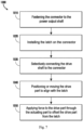
- Figure 7 is a flowchart showing the steps of the method for assembling or operating the connecting device of the tool assembly (the "method 1000" hereinafter) according to one embodiment.
- the method 1000 may be used for motorized tools (for example, electric or pneumatic machines) or hand-driven tools.
- the tool assembly may comprise an auger tool or another tool head.
- the method 1000 comprises a step 1010 of fastening a connecting body (for example, the connector 110) to an output shaft (for example, the output shaft 16) for outputting power.
- the method 1000 comprises a step 1010 of extending a fastener (for example, a first fastener) along the extending direction of the output shaft to fasten the connecting body to the output shaft.
- the method 1000 comprises a step 1010 of extending a fastener along the extending direction of the output shaft in the connecting body to fasten the connecting body to the output shaft.
- fastening the connecting body to the output shaft allows the output shaft and connecting body to rotate together.
- the method 1000 comprises a step 1020 of fastening a latch 120 to the connecting body (for example, the connector 110, such as a connecting shaft).
- the method 1000 comprises a step 1020 of extending a second fastener through the connecting body and the latch in a direction substantially perpendicular or oblique to the axis of extension of the first fastener.
- the method 1000 comprises a step 1020 of extending the fastener through the connecting body and the latch.
- the latch fastened to the connecting body allows the latch to rotate with the connecting body, for example, as described in step 1010 of the method 1000.
- fastening the latch to the connecting body allows the latch to pivot or rotate relative to the axis of extension of the second fastener.
- the method 1000 comprises a step 1030 of selectively connecting a drive shaft 26 to the connecting body (for example, the connector 110).
- the method 1000 comprises a step 1030 of rotating or pivoting the latch to a groove.
- the method 1000 comprises a step 1030 of rotating or pivoting the latch along the axis of the second fastener to selectively lock the latch in a groove of the drive shaft.
- the method 1000 comprises a step 1030 of extending the drive shaft into the connecting body along the axis of extension of the connecting body.
- the axis of extension of the connecting body is substantially perpendicular or oblique to the axis of extension of the second fastener extending through the latch and connecting body.
- the axis of extension of the connecting body is substantially in the same direction as the axis of extension of the first fastener connected to the output shaft.
- the method 1000 comprises a step 1040 of positioning or moving a drive part 130 (for example, a sleeve) along the axis of extension of the connecting body to align with the latch.
- the method 1000 comprises a step 1040 of sliding the drive part 130 along the axis of extension of the connecting body so that the drive part 130 encircles the latch as the latch rotates into the groove on the drive shaft.
- the method 1000 comprises a step 1050 of transmitting force through an actuating part 150 to the drive part 130 to move the drive part 130 from the state where it is aligned with the latch 120.
- the method 1000 comprises a step 1050 of pivoting or rotating the actuating part about an axis substantially in the same direction as the axis of extension of the second fastener extending through the latch and the connecting body.
- the method 1000 comprises a step 1050 of applying a force opposite to the biasing force (for example, a force opposite to the first elastic part 140) to move the drive part.
- the method 1000 further comprises a step 1 of allowing the biasing force to position the drive part, for example, a sleeve, around the latch. In some embodiments, the method 1000 further comprises a step of stopping or reducing the force applied in step 1050 to allow a biasing force to act on the drive part to move or position the drive part around the latch. In some embodiments, the method 1000 comprises a step 2 of applying a force to the drive part to rotate the latch into the groove on the drive shaft. In various embodiments, applying a force to the drive part comprises positioning or moving the drive part to the latch so that the latch rotates to lock the drive shaft in the connecting body. In various embodiments, the force applied in step 2 comprises a biasing force provided by a first elastic part 140 or a force applied by the user along the extension axis of the connecting body.
- the tool assembly 10, the connecting device 100 or the method 1000 provided by the present invention provides a locking assembly to selectively connect the tool head 20 to the tool assembly 10 or to disengage the tool head 20 from the tool assembly 10.
- the connecting device 100 further provides a lock and key assembly to allow quick and safe operation of the actuating part 150 (for example, an operating rod), insertion or removal of the tool bit 20 (for example, an auger bit, a machine bit, or another suitable tool bit), and releasing of the actuating part 150 to position and lock the tool head 20 at the drive shaft 26.
- the tool assembly 10 and the connecting device 100 provided by the present invention can allow the tool head to be selected for positioning, for example, can reduce or avoid connecting an unnecessary or inappropriate tool, and mitigate the operational, execution and safety risks associated with combining an incompatible or unnecessary tool head and a tool due to confusion.
Landscapes
- Engineering & Computer Science (AREA)
- Life Sciences & Earth Sciences (AREA)
- Geology (AREA)
- Mining & Mineral Resources (AREA)
- Mechanical Engineering (AREA)
- Physics & Mathematics (AREA)
- Environmental & Geological Engineering (AREA)
- Fluid Mechanics (AREA)
- General Life Sciences & Earth Sciences (AREA)
- Geochemistry & Mineralogy (AREA)
- Portable Nailing Machines And Staplers (AREA)
- Percussive Tools And Related Accessories (AREA)
Abstract
Description
- The present invention relates to the field of tools, and in particular to a connecting device and a tool comprising the connecting device.
- Tools are configured to receive tool heads, for example, pneumatic or electric augers, drill bits, and machine tools. Various tools are configured for specific tasks and may comprise a power unit configured for specific purposes, for example, powering an auger attachment or drill bit. However, engaging different tool heads with different power units may create operational, performance or safety risks to the tool or the user. The combination of a tool head and a power unit may result in unreliable or insufficient coupling of the power or torque provided by the power unit.
- In view of the foregoing background, the present invention provides a structure and a method for connecting a tool head to a power unit. More specifically, the structure and the method for connecting a tool head to a power unit are advantageous in that the structure and the method can establish a secure connection of a tool head to the tool, mitigate incomplete or unreliable mechanical connection between the tool head and the tool, or reduce operational, performance and safety risks associated with the connection between the tool head and the tool.
- To achieve the above purpose, in a first aspect, the present invention provides a connecting device used for connecting a tool. A longitudinal direction, a transverse direction and a vertical direction perpendicular to each other are defined for the connecting device, and a first end and a second end spaced apart are provided in the longitudinal direction. The connecting device comprises: a connector, which has an inner cavity extending in the longitudinal direction, a tool end opening connected to the inner cavity and a latch opening connected to the inner cavity, wherein the tool end opening is configured to allow a drive shaft of a tool head to pass through it into the inner cavity in the longitudinal direction; a latch, which is located in the inner cavity and is capable of moving between a locked position and an unlocked position, the latch comprising an engaging portion, which is configured to engage with a corresponding mating portion on the drive shaft entering the inner cavity in the locked position and is disengaged from the mating portion in the unlocked position; and a drive part, which is provided on the connector and is capable of being driven on the latch opening along the longitudinal direction to drive the latch to move.
- In this technical solution, the latch is located in the inner cavity and is capable of moving between the locked position and the unlocked position and the drive part is provided on the connector and is capable of being driven on the latch opening along the longitudinal direction to drive the latch to move, thus the connector can be connected to the output shaft of a tool, the engaging portion is configured to engage with the corresponding mating portion on the drive shaft entering the inner cavity in the locked position, and the engaging portion is disengaged from the mating portion in the unlocked position, and therefore, through this mating relationship between the latch and the drive part, in the locked position, the latch of the inner cavity can lock the drive shaft of the tool head extending into the inner cavity, to securely connect the connector and the tool head, and in the unlocked position, the latch unlocks the drive shaft, to allow the drive shaft to be taken out from the inner cavity. Therefore, it can establish a secure connection of the tool head to the tool, mitigate incomplete or unreliable mechanical connection between the tool head and the tool, and reduce operational, performance and safety risks associated with the connection between the tool head and the tool.
- In some embodiments, the connector is formed with a first opening extending along the transverse direction, and the latch is formed with a second opening extending along the transverse direction, wherein the latch is connected to the connector by use of a pivot that passes through the first opening and the second opening.
- In some embodiments, the latch is pivotably provided on the connector to allow the latch to move in the vertical direction.
- In some embodiments, the latch comprises a stop end extending toward the second end along the longitudinal direction and a connecting portion located between the stop end and the engaging portion, and an accommodating space for accommodating a drive shaft end of the drive shaft is formed between the connecting portion and the engaging portion.
- In some embodiments, the connecting portion comprises a first inclined surface, and the first inclined surface is configured to be capable of contacting a drive inclined surface of the drive shaft end.
- In some embodiments, the engaging portion is formed with a second inclined surface, and the second inclined surface is configured to be in sliding contact with the drive inclined surface of the drive shaft end of the drive shaft when the drive shaft extends into the inner cavity.
- In some embodiments, the connecting device further comprises a first elastic part, the first elastic part is arranged between the drive part and a stop portion of the connector to store energy when the drive part is driven, the first elastic part, when releasing energy, is capable of biasing the drive part to an initial position, and, in the initial position, the drive part keeps the latch in the locked position.
- In some embodiments, the connecting device further comprises a pivotably arranged actuating part, and the pivot axis of the actuating part extends along the transverse direction, wherein, the actuating part is capable of driving the drive part to move from the initial position to a released position under an action of an external force applied by an operator; when in the initial position, the drive part keeps the latch in the locked position, and when in the released position, the drive part allows the latch to be in the unlocked position.
- In some embodiments, the actuating part comprises an open mouth, and the connector extends through the open mouth, wherein at least two opposite edges of the open mouth contact the drive part.
- In some embodiments, contact protrusions in contact with the drive part are respectively formed on the at least two opposite mouth edges.
- In some embodiments, the actuating part is an actuating plate.
- In some embodiments, the actuating part is an elastic actuating part.
- In some embodiments, the latch comprises a latch protrusion, and, when the actuating part drives the drive part to move from the initial position to the released position, the drive part drives the latch protrusion to drive the latch to move from the locked position to the unlocked position.
- In some embodiments, a second elastic part acting on the latch is provided in the inner cavity, wherein, the second elastic part stores energy when the latch moves from the locked position to the unlocked position, wherein the second elastic part, when releasing energy, biases the latch to the locked position.
- In some embodiments, a connector power input end of the connector has a connecting part, and the connecting part is configured to securely connect the connector power input end to an upstream power output end, wherein a part of the second elastic part serves as a connecting gasket of the connecting part.
- In some embodiments, the second elastic part is a U-shaped elastic piece, one elastic side wall of the U-shaped elastic piece acts on the stop end of the latch, another elastic side wall of the U-shaped elastic piece is used as a supporting side wall, and a bottom wall of the U-shaped elastic piece is used as the connecting gasket, wherein, a mounting hole is formed on the bottom wall, and the connecting part passes through the mounting hole and extends toward the second end along the longitudinal direction in the inner cavity.
- In some embodiments, an accommodating channel is formed on an end surface of the connector power input end, the accommodating channel is configured to accommodate a power output shaft upstream of power transmission, a through hole is formed on a spacer side wall between the accommodating channel and the inner cavity, and the connecting part extends from the inner cavity through the through hole into the accommodating channel to connect to the power output shaft, so that the connector and the power output shaft are connected to each other.
- In some embodiments, the actuating part is configured to protrude from the actuator opening on the housing of the tool; or, the actuating part is configured to engage with a drive button movably arranged on the housing of the tool, and the actuating part is capable of pivoting under the drive of the drive button.
- In a second aspect, the present invention provides a tool, which comprises: a power unit, which outputs power through a power output shaft; and the connecting device described in any paragraph in the first aspect above; wherein the power output shaft and the connector are connected in a power transmitting manner.
- In some embodiments, the tool further comprises a detachably installed battery unit, and the battery unit provides driving power to a driving motor of the power unit.
- In some embodiments, the tool further comprises a tool head, and a drive shaft of the tool head passes through the tool end opening into the inner cavity in the longitudinal direction, wherein, the mating portion of the drive shaft engages with the engaging portion in the locked position, and the engaging portion is disengaged from the mating portion in the unlocked position.
- In some embodiments, the tool head is an auger bit.
- In some embodiments, the tool further comprises a housing, an actuator opening is formed on the housing, and an actuating part protrudes from the actuator opening; or, a movable drive button is provided on the housing, the actuating part engages with the drive button, and the actuating part is capable of pivoting under the drive of the drive button.
- Other features and aspects of the present invention will become apparent upon consideration of the following detailed description and the accompanying drawings.
-
-
Figure 1 is a space view of a first embodiment of the tool according to some aspects of the present invention; -
Figure 2 is a space view of a first embodiment of the connecting device of the tool assembly according to some aspects of the present application, wherein some other components of the tool are shown. -
Figure 3 is an exploded space view of the connecting device ofFigure 2 ; -
Figure 4 is a cut-away space view of the connecting device ofFigure 2 ; -
Figure 5 is a detail structural diagram of the connecting device ofFigure 4 , wherein some components of the connecting device are omitted; -
Figure 6 is a space view of a first embodiment of the connecting device according to some aspects of the present invention; -
Figure 7 is an overview of the steps of the method for assembling or operating the connecting device according to some aspects of the present invention; -
Figure 8 is a space view of a second embodiment of the tool according to some aspects of the present invention; -
Figure 9 is a space view of the tool ofFigure 8 with a part of the housing and the tool head removed; -
Figure 10 is a space view of the elastic actuating part inFigure 9 ; -
Figure 11 is a space view of a second embodiment of the connecting device of the tool assembly according to some aspects of the present application, wherein a part of the drive shaft of the tool head is shown, wherein the latch is in the unlocked position; -
Figure 12 is a space view ofFigure 11 with the connector removed; -
Figure 13 is a space view of the connecting device ofFigure 11 from another perspective, wherein a part of the drive shaft is removed; -
Figure 14 is a space view of a second embodiment of the connecting device of the tool assembly according to some aspects of the present application, wherein a part of the drive shaft of the tool head is shown, wherein the latch is in the locked position; -
Figure 15 is a space view ofFigure 14 with the connector removed; -
Figure 16 is a space view ofFigure 15 with the drive part and a part of the drive shaft removed; -
Figure 17 is a space view of the connecting device ofFigure 14 from another perspective, wherein a part of the drive shaft is removed. - Before any embodiment of the present invention is described in detail, it should be understood that the application of the present invention is not limited to the details of construction and arrangement of components set forth in the following description or illustrated in the following drawings. The present invention can have other embodiments and can be put into practice or implemented in various ways. In addition, it should be understood that the phraseology and terminology used herein are for the purpose of description and may not be regarded as limiting.
- In the following detailed description of the embodiments, description is made by referring to the accompanying drawings which constitute a part of the description. The drawings show, by way of examples, specific embodiments in which the present invention is implemented. The illustrated embodiments are not intended to be exhaustive of all embodiments according to the present invention. It should be understood that other embodiments may be utilized and structural or logical changes may be made without departing from the scope of the present invention. With respect to the drawings, directional terms, such as "lower", "upper", "left", "right", etc., are used by referring to the orientation of the drawings being described. Since the components of the embodiments of the present invention may be implemented in a variety of orientations, these directional terms are used for the purpose of illustration, but not limitation. Therefore, the detailed description below is not intended to be limiting, and the scope of the present invention is defined by the appended claims.
- Referring to the drawings now,
Figure 1 provides an exemplary embodiment of the tool assembly 10 having atool head 20.Figures 2 to 6 provide an exemplary embodiment of the connectingdevice 100. The connectingdevice 100 is configured to operatively connect the tool head 20 (for example, an auger attachment, drill bit or other mechanical drill bit) to the tool 10. In various embodiments, thetool head 20 comprises a shank orshaft 22 extending along thelongitudinal direction 101. The tool surface 24 (for example, a blade, groove or another tool component) extends from theshaft 22. In some embodiments, thetool head 20 may be formed as an auger attachment. The tool assembly 10 may comprise apower unit 12, and thepower unit 12 is configured to output power or torque to thetool head 20. The tool assembly 10 may generally comprise ahandle 14, and a user can hold thehandle 14 and operate and control the tool assembly 10. Theattachment connection 15 is formed where the tool assembly 10 and thetool head 20 are connected to each other. In some embodiments, the connectingdevice 100 is formed or positioned at theattachment connection 15, and thetool head 20 and the tool assembly 10 are operably connected to each other at theattachment connection 15. - With reference to
Figures 1 to 6 , between thefirst end 101 and thesecond end 102, the extension of the referencedlongitudinal direction 103 coincides with the extension of thetool head 20, in particular with the extension of theshaft 22 of thetool head 20. Thelongitudinal direction 103 may form the axis along which theshaft 22 or the connector (for example, a connecting shaft) 110 extends. Thefirst end 101 forms the tool end, thetool head 20 is configured at this tool end to contact a surface, object, structure or another working surface (for example, a field into which an auger may penetrate). Thetool head 20 is configured to receive power or torque from thepower unit 12, and thepower unit 12 may comprise, for example, an electric motor for driving the tool head and a power source such as a battery or a gas engine. Thesecond end 102 forms an operating end, a user can hold and operate the tool assembly 10 at this end. Thevertical direction 105 and thetransverse direction 104 are respectively perpendicular to thelongitudinal direction 103. Therefore, thelongitudinal direction 103, thetransverse direction 104 and thevertical direction 105 are perpendicular to each other. Thevertical direction 105 and thetransverse direction 104 respectively extend through theconnector 110 from a centreline formed by thelongitudinal direction 103. The radial direction may essentially extend from the centreline through theconnector 110. - With reference to
Figures 2 to 6 , the connectingdevice 100 comprises a connector orconnector shaft 110 releasably connected to theoutput shaft 16 of the tool assembly 10. Thedrive shaft 26 is releasably connected to theconnector 110. In various embodiments, thedrive shaft 26 forms part of thetool head 20. In some embodiments, thedrive shaft 26 forms a shaft extending from the shank orshaft 22, and thetool surface 24 is formed or extends at the shank orshaft 22. Theconnector 110 extends along thelongitudinal axis 103. Theconnector 110 is formed with aninner cavity 112 extending along thelongitudinal direction 103. Theinner cavity 112 formed in theconnector 110 is capable of allowing thedrive shaft 26 to extend into theinner cavity 112 along thelongitudinal direction 103. In some embodiments, theinner cavity 112 formed in theconnector 110 is capable of allowing thedrive shaft 26 to extend into theinner cavity 112 from thefirst end 101 toward thesecond end 102 along thelongitudinal direction 103. - In some embodiments, the
connector 110 comprises abody 114 extending along thelongitudinal direction 103. In various embodiments, thebody 114 forms an essentially cylindrical body extending along thelongitudinal direction 103. It should be understood that thebody 114 may comprise walls, depressions, grooves or surfaces extending from thebody 114. Thetool end opening 116 is formed close to thefirst end 101 and is configured to receive thedrive shaft 26 along thelongitudinal direction 103. - The
connector 110 is formed with alatch opening 118 to provide access to theinner cavity 112 along thevertical direction 105. Thelatch opening 118 allows thelatch 120 to be inserted through theconnector 110 into theinner cavity 112. In some embodiments, thelatch opening 118 is formed to pass through the longitudinal extension of thebody 114. In some embodiments, thelatch opening 118 extends along thelongitudinal direction 103 to form a longitudinally extending slot into theinner cavity 112. - The
latch 120 forms a member extending in thelongitudinal direction 103. Thelatch 120 is configured to be positioned into theinner cavity 112 through thelatch opening 118. In various embodiments, thelatch 120 comprises an engagingportion 122 extending in the vertical direction, for example, an engaging protrusion. In some embodiments, the engagingportion 122 extends from thefirst latch end 125 along thevertical direction 105, and thefirst latch end 125 is close to thefirst end 101 in thelongitudinal direction 103. Thelatch 120 may further form a second latch end or stopend 124 close to thesecond end 102 in the longitudinal direction. In some embodiments, thelatch 120 is formed with astop end 124 extending in theinner cavity 112 inwardly from thesecond connector end 115 along thevertical direction 105. In some embodiments, thesecond connector end 115 forms a part of theconnector 110 along thelongitudinal direction 103 and is arranged close to thesecond end 102 from thelatch opening 118. Thefirst connector end 113 forms a part of theconnector 110 along thelongitudinal direction 103 and is arranged close to thefirst end 101 from thelatch opening 118. In various embodiments, the engagingportion 122 is positioned close to thefirst connector end 113 along thelongitudinal direction 103. It should be understood that thefirst latch end 125 is closer to thefirst end 101 than the second latch end or stopend 124 is. Additionally, the second latch end or stopend 124 is closer to thesecond end 102 than thefirst latch end 125 is. - With reference to
Figures 2 to 6 , especiallyFigures 4 and5 , thelatch 120 in various embodiments may comprise a connectingportion 126, for example, an arm, and the connectingportion 126 extends at least partially along thevertical direction 105. The connectingportion 126 may form a transition portion of thelatch 120 between the engagingportion 122 and thestop end 124. In some embodiments, the connectingportion 126 extends along thevertical direction 105 and positions thestop end 124 in thecavity 112 inside thesecond connector end 115 along thevertical direction 105. - In various embodiments, the
drive shaft 26 is formed with amating portion 262, for example, a groove. Themating portion 262 is configured to engage with the engagingportion 122 of thelatch 122. For example, a groove is configured to receive an engaging protrusion of thelatch 122. In some embodiments, themating portion 262, for example, a groove, extends substantially from theouter surface 260 along thevertical direction 105. Thedrive shaft 26 may be formed with a drive shaft second end or driveshaft end 261. Thedrive shaft end 261 is formed with a driveinclined surface 266 extending at least partially along thevertical direction 105. The drive shaft second end or driveshaft end 261 substantially corresponds to the accommodating space between the connectingportion 126 and the engagingportion 122 of thelatch 120. For example, the drive inclinedsurface 266 substantially corresponds to the firstinclined surface 127 of the connectingportion 126. For example, the connectingportion 126 comprises a firstinclined surface 127 facing the first end, and the firstinclined surface 127 is configured to be capable of contacting the drive inclinedsurface 266 of thedrive shaft end 261. In some embodiments, the firstinclined surface 127 and the drive inclinedsurface 266 extend at an acute angle respectively along thevertical direction 105 andlongitudinal direction 103. Correspondingly, the drive inclinedsurface 266 may be positioned between the engagingportion 122 and the connectingportion 126 along thelongitudinal direction 103. In addition, a groove formed in thedrive shaft 26 is configured to receive the engagingportion 122 of thelatch 122 when thedrive shaft 26 extends into theinner cavity 112. In theinner cavity 112, the engagement between the engagingportion 122 and themating portion 262, for example, an engaging protrusion positioned in a groove, limits the movement of thedrive shaft 26 along thelongitudinal direction 103. - With reference to
Figures 2 and3 , theconnector 110 may be formed with afirst opening 119 extending in thetransverse direction 104. With reference toFigures 4 and5 , thelatch 120 may be formed with asecond opening 129 extending in thetransverse direction 104. With reference toFigures 2 to 6 , thefirst opening 119 and thesecond opening 129 are configured to correspond to each other to be aligned along thelongitudinal direction 103. Thefirst opening 119 and thesecond opening 129, when aligned along thelongitudinal direction 103, may allow a shaft, pin, rod, shank, fastener or another member to extend through thefirst opening 119 and thesecond opening 129. Thefirst opening 119 and thesecond opening 129 may allow thelatch 120 to pivot in theinner cavity 112. Specifically, a member extending through thefirst opening 119 and thesecond opening 129 may allow thelatch 120 to pivot at thesecond opening 129 to selectively connect the engagingportion 122 along thevertical direction 105. In some embodiments, thesecond opening 129 is positioned between thestop end 124 and the engagingportion 122 along thelongitudinal direction 103. In some embodiments, thesecond opening 129 is positioned on the connectingportion 126, or at the end of the connectingportion 126, to allow thelatch 120 to pivot at thesecond opening 129. - With reference to
Figures 2 to 6 , the drive part 130 (for example, a sleeve, semicircular tube or any other type of member) may extend around theconnector 110. In various embodiments, thedrive part 130 may extend circumferentially around theconnector 110. In addition, thedrive part 130 may move along thelongitudinal direction 130 to selectively lock thelatch 120. For example, a sleeve may move along thelongitudinal direction 130 to selectively encircle thelatch 120. Thedrive part 130 can keep thedrive shaft 26 in theconnector 110 when locking the latch 120 (for example, when a sleeve encircles the latch 120). In some embodiments, a sleeve encircling thelatch 120 may retain or constrain an engaging protrusion on thelatch 120 in a groove of thedrive shaft 26. The engaging protrusion, when in the groove, can retain thedrive shaft 26 in theinner cavity 112 and limit or prevent the movement of thedrive shaft 26 in thelongitudinal direction 103. - In addition, with reference to the different embodiments shown in
Figures 5 and12 , the engagingportion 122 is formed with a secondinclined surface 123, and the secondinclined surface 123 is configured to be in sliding contact with the drive inclinedsurface 266 of thedrive shaft end 261 of thedrive shaft 26 when thedrive shaft 26 extends into theinner cavity 112. In this way, when thedrive shaft 26 extends into theinner cavity 112 through thetool end opening 116, the drive inclinedsurface 266 will come into contact with the secondinclined surface 123, and as thedrive shaft 26 moves toward thefirst end 101, the secondinclined surface 123 and the drive inclinedsurface 266 are in sliding contact, to drive the latch to pivot upward, thus making it easier for the latch to pivot. - With reference to
Figures 2 to 6 , themotor 30 is configured to output energy to rotate theconnector 110. In some embodiments, thetransmission assembly 40 is operatively connected between themotor 30 and theconnector 110. Thetransmission assembly 40 may be configured to receive energy from themotor 30 and convert that energy into torque that can rotate theconnector 110. Themotor 30 may comprise any suitable power unit configured to output energy to rotate theoutput shaft 16. Thetransmission assembly 40 may comprise any suitable type of torque converter, which may comprise one or more gear sets and is configured to receive energy from themotor 30 and output power and torque through theconnector 110. In some embodiments, thepower unit 12 of the tool assembly 10 comprises amotor 30 and atransmission assembly 40. However, in some embodiments, thepower unit 12 may comprise a manually actuated power unit configured to transmit power from a user to the tool head. - In some embodiments, for example, the embodiments shown in the cut-away views of a part of the tool assembly 10 comprising the connecting
device 100 provided inFigures 3 and4 , thetransmission assembly 40 may comprise anoutput shaft 16, and torque and power are transmitted from theoutput shaft 16 to theconnector 110. In various embodiments, theoutput shaft 16 comprises a threadedconnection 160, and the threadedconnection 160 is configured to receive a mechanical fastener, for example, a connecting part 191 (for example, typically a threaded shank and head, screw, bolt, tie rod, etc. The mechanical fastener is omitted for clarity). In some embodiments, the threadedconnection 160 extends along thelongitudinal direction 103. Theconnector 110 may comprise aspacer side wall 111 extending along thevertical direction 105 in theinner cavity 112. Theconnector 110 is formed with anoutput shaft opening 117, and theoutput shaft 117 is close to thesecond end 102 in the longitudinal direction 103 (i.e., away from the tool end opening 116 that is close to thefirst end 101 in the longitudinal direction 103). Theoutput shaft opening 117 allows theoutput shaft 16 to enter theinner cavity 112 along thelongitudinal direction 103. Thespacer side wall 111 is positioned between theoutput shaft opening 117 and the tool end opening 116 to allow theoutput shaft 16 to enter theinner cavity 112. Theoutput shaft 16 can in particular extend along thelongitudinal direction 103 and adjoin thespacer side wall 111 inside theinner cavity 112. - A mechanical fastener can enter the
inner cavity 112 through thetool end opening 116. The threaded end of the mechanical fastener can extend through thespacer side wall 111 and engage with the threadedconnection 160 of theoutput shaft 16. The head of the threaded fastener may be configured to adjoin thespacer side wall 111 to securely fasten theconnector 110 to theoutput shaft 16. When assembled, the mechanical fastener extends along thelongitudinal direction 103 through thespacer side wall 111 in theinner cavity 112 and connects to theoutput shaft 16 at the threadedconnection 160. Thelatch 120 can then be positioned at least partially in theinner cavity 112 to allow alignment of thefirst opening 119 and thesecond opening 129 such that a fastener, for example, a pin, shank, shaft, etc., can extend through thefirst opening 119 and thesecond opening 129 along thetransverse direction 104 to connect thelatch 120 to theconnector 110. Thelatch 120 can desirably and optionally rotate the engagingportion 122 substantially in the vertical direction. Thedrive shaft 26 extends in thelongitudinal direction 103 through the tool end opening 116 into theinner cavity 112. Thelatch 120 can rotate the engagingportion 122 at least partially out of theinner cavity 112 to allow the positioning of thedrive shaft 26 along thelongitudinal direction 103 and to allow theengaging portion 122 to align with the groove of thedrive shaft 26 and be positioned in the groove. - In various embodiments, the
drive part 130, for example, a sleeve, can be positioned around theconnector 110, for example, a connector shaft. In some embodiments, thedrive part 130 can move from thesecond end 102 toward thefirst end 101 along the longitudinal direction. When thedrive part 130 is positioned around thelatch 120, theconnector 110 is connected to theoutput shaft 16. - With reference to
Figure 4 , in some embodiments, the connectingdevice 100 further comprises a firstelastic part 140, and the firstelastic part 140 is arranged between thedrive part 130 and astop portion 142 of theconnector 110 to store energy when thedrive part 130 is driven. For example, when the drive acting on thedrive part 130 is eliminated, the firstelastic part 140 can release energy to drive thedrive part 130 to return. For example, the firstelastic part 140, when releasing energy, can bias thedrive part 130 to the initial position. In the initial position, thedrive part 130 keeps thelatch 120 in the locked position. In some embodiments, thestop portion 142 may be a separate component or a part of theconnector 110. In some embodiments, the firstelastic part 140 can be positioned between thedrive part 130 and thetransmission assembly 40. In some embodiments, the firstelastic part 140 extends along thelongitudinal direction 103 and acts on thedrive part 130 and thestop portion 142, for example, a surface, extending around theconnector 110, and thestop portion 142, for example, a surface, is located at thesecond end 102 or close to thesecond end 102. Thestop portion 142 may be a gasket, plate or wall extending radially outward from theconnector 110. Thestop portion 142 may be positioned close to thetransmission assembly 40 along thelongitudinal direction 103. The firstelastic part 140 may apply a force to bias thedrive part 130 to thelatch opening 118 along thelongitudinal direction 103. Accordingly, thedrive part 130 may be biased to retain thelatch 120 in thelatch opening 118. In addition, the firstelastic part 140 may be a spring, an elastic sleeve, an elastic frame, an elastic piece or another elastic component. In addition, the firstelastic part 140 may be sleeved on theconnector 110, or a plurality of firstelastic parts 140 may be arranged circumferentially around theconnector 110 at an interval. - In some embodiments, the
drive part 130, for example, a sleeve, may form a tight fit interface, in which friction between thedrive part 130 and theconnector 110 or thelatch 120 holds thedrive part 130 on thelatch opening 118. The user may apply force along thelongitudinal direction 103 toward thesecond end 102 to selectively drive thedrive part 130 to allow theengaging portion 122 of thelatch 120 to rotate into the groove of thedrive shaft 26 or out from thedrive shaft 26. - Referring to
Figures 1 to 6 , in various embodiments, the connectingdevice 100 comprises a component, for example, anactuating part 150. In some embodiments, the connecting device further comprises a pivotably arranged actuating part, and the pivot axis of the actuating part extends along the transverse direction, wherein, the actuating part is capable of driving the drive part to move from the initial position to a released position under an action of an external force applied by an operator; when in the initial position, the drive part keeps the latch in the locked position, and when in the released position, the drive part allows the latch to be in the unlocked position. Theactuating part 150 is configured to receive a force substantially along thelongitudinal direction 103 to selectively act on thedrive part 130, thus moving thedrive part 130 along thelongitudinal direction 103. In some embodiments, the connectingdevice 100 further comprises a pivotably arranged actuatingpart 150, and the pivot axis of theactuating part 150 extends along the transverse direction, wherein, theactuating part 150 is capable of driving thedrive part 130 to move from the initial position to the released position under the action of an external force applied by an operator. When in the initial position, thedrive part 130 keeps thelatch 120 in the locked position, and at this point thelatch 120 keeps thedrive shaft 26 in theconnector 110. When in the released position, thedrive part 130 allows thelatch 120 to be in the unlocked position, and at this point thelatch 120 allows thedrive shaft 26 to be able to move into and out of theinner cavity 112 along thelongitudinal direction 103. - In addition, the
actuating part 150 may be of various types. No matter which type is used, it is only necessary for theactuating part 150 to be able to receive a force substantially along thelongitudinal direction 103 to selectively drive thedrive part 130 to move. For example, in some embodiments, referring toFigures 2 and3 , theactuating part 150 is anactuating plate 152. In this way, a force substantially along thelongitudinal direction 103 can act on theactuating plate 152 to pivot theactuating plate 152, and thus theactuating plate 152 can drive thedrive part 130 to move. In addition, theactuating plate 152 can be reversely pivoted to return under the action of an opposite external force, or theactuating plate 152 can be reversely pivoted to return under the drive of the firstelastic part 140 described above. For example, the firstelastic part 140 can drive thedrive part 130 to move reversely to return, and thedrive part 130 drives theactuating plate 152 to reversely pivot to return. For another example, in some embodiments, referring toFigures 9 and10 , theactuating part 150 is anelastic actuating part 153, for example, an actuating spring. In this way, in some embodiments, theelastic actuating part 153 can reversely pivot to return under its own elastic force. In addition, in some implementations, if necessary, the firstelastic part 140 can drive thedrive part 130 to move reversely to return, and thedrive part 130 acts on theelastic actuating part 153 so that theelastic actuating part 153 quickly pivots reversely to return under the double drive of its own elastic force and thedrive part 130. - In addition, in some embodiments, the
actuating part 150 may be formed in the shape of a fork, a rod or a plate. For example, referring toFigures 3 and10 , theactuating part 150 comprises anopen mouth 154, and theconnector 110 extends through theopen mouth 154, wherein at least two opposite edges of theopen mouth 154 contact thedrive part 130. In this way, with the opposite mouth edges in contact with thedrive part 130, the stability and reliability of driving thedrive part 130 can be effectively improved. In addition, in some embodiments, to improve the driving stability between the actuatingpart 150 and thedrive part 130, referring toFigures 2 ,3 ,9 and10 ,contact protrusions 158 in contact with thedrive part 130 are respectively formed on the at least two opposite mouth edges. In this way, thecontact protrusions 158 can not only reduce the contact area between thedrive part 130 and theactuating part 150, but also improve the smoothness of the relative movement between thedrive part 130 and theactuating part 150. In addition, in some embodiments, thecontact protrusions 158 are configured to contact the radially outwardly extendingwall 132 of a sleeve. In some embodiments, thecontact protrusions 158 can extend from theactuating plate 152 or theelastic actuating part 153 along thelongitudinal direction 103 toward thesecond end 102. - In some embodiments, the
actuating part 150 is formed with apin 156, and thepin 156 is configured to be positioned in a housing encircling at least a part of theconnector 110 and to be capable of rotating. In some embodiments, referring toFigure 6 , the connectingdevice 100 may comprise aseparate housing 170 or ahousing 170 forming part of thehousing 18 of the tool assembly 10 (referring toFigure 1 ), and thehousing 170 encircles theconnector 110. Thehousing 170 may comprise a plurality of walls, and the plurality of walls are configured to substantially encircle theconnector 110 and the components connected to theconnector 110. In some embodiments, thehousing 170 may form part of thehousing 18 of the tool assembly 10 (referring toFigure 1 ). Thehandle 14 may extend from thehousing 18 and form a grip or a control interface, and a user may operate the grip or the control interface and use the tool assembly 10. Thehousing 170 may be formed with apin opening 176, and thepin 156 of theactuating part 150 may be positioned in thepin opening 176. Thepin 156 in thepin opening 176 can allow theactuating part 150 to pivot toward thefirst end 101 and thesecond end 102. Thehousing 170 may be formed with anactuator opening 178 to allow a part of theactuating part 150 to protrude from thehousing 170. - In an exemplary method of operation, a user may apply force to the
actuating part 150 so that theactuating part 150 pivots about thepin 156 and comes into contact with the drive part 130 (for example, thecontact protrusions 158 come into contact with the drive part 130) to move thedrive part 130 along thelongitudinal direction 103. For example, in some embodiments, a user may contact the end of theactuating plate 152 away from thepin 156. The far end of theactuating plate 152 may protrude from thehousing 170 through theactuator opening 178. Theactuating part 150 can act as a lever or a moment arm, thereby making it easier for the user to conveniently drive thedrive part 130, for example, a sleeve, along thelongitudinal direction 103. - The
actuator opening 178 may be formed as a slot extending along thelongitudinal direction 103, thereby allowing theactuating part 150 to pivot toward thefirst end 101 and thesecond end 102. The contact protrusions 158 on theactuating part 150 can contact thewall 132 on thedrive part 130. The force applied by the user can be transmitted to thedrive part 130 through thecontact protrusions 158, thereby causing thedrive part 130 to move toward thesecond end 102. This movement of thedrive part 130 along thelongitudinal direction 130 toward thesecond end 102 allows thelatch 120 to rotate freely (for example, around a pin, a fastener, etc., in the second opening 129) out of the groove and away from thedrive shaft 26. In some embodiments, after thedrive part 130 moves toward thesecond end 102 and out of thelatch opening 118, the user can pull or slide thedrive shaft 26 along thelongitudinal direction 103 toward thefirst end 101. When thedrive shaft 26 is moved in thelongitudinal direction 103 toward thefirst end 101, thedrive part 130 moving away from thelatch 120 allows thelatch 120 to rotate upward in thevertical direction 105. For example, the part of the groove positioned toward thesecond end 102 may contact the engagingportion 122. As thedrive shaft 26 moves away from thesecond end 102 in thelongitudinal direction 103, the groove drives the engagingportion 122 in thevertical direction 105. As thedrive shaft 26 moves toward thefirst end 101 in thelongitudinal direction 103, the groove and the corresponding inclined surface of the engagingportion 122 drive the engagingportion 122 on thelatch 120 in thevertical direction 105. In addition, the groove may be a semicircular groove, and the engaging protrusion may be a semicircular protrusion. - In various embodiments, when the reaction force applied to the drive part 130 (for example, through the actuating part 150) is weakened or removed, the first
elastic part 140 can push thedrive part 130 toward thefirst end 101 onto thelatch opening 118 along thelongitudinal direction 103. Thedrive part 130 can contact thelatch 120 to rotate thelatch 120 into theinner cavity 112. When thedrive shaft 26 is correspondingly positioned into theinner cavity 112, thedrive part 130 can contact the engagingportion 122 on thelatch 120 and rotate the engagingportion 122 into the groove. Referring to the embodiment shown inFigures 4 and5 , thedrive part 130 can secure or lock thelatch 120 to the groove, and thelatch 120 can lock thedrive shaft 26 in place along thelongitudinal direction 103. Compared with tool connection ends that are not provided with an engaging surface on thelatch 120, the embodiments of the present invention can prevent the connection of anunsafe tool head 20 to the tool assembly 10, i.e., these embodiments of the present invention can effectively improve the reliability of connection between thetool head 20 and the tool assembly 10. - In addition, in some embodiments, referring to the different states shown in
Figures 11 to 17 , thelatch 120 comprises alatch protrusion 155, and, when theactuating part 150 drives thedrive part 130 to move from the initial position to the released position, thedrive part 130 drives thelatch protrusion 155 to drive thelatch 120 to move from the locked position to the unlocked position. In this way, by this cooperation between thelatch projection 155 and thedrive part 130, for example, a sleeve, thelatch 120 can be easily driven to pivot between the locked position and the unlocked position. - In addition, in some embodiments, referring to
Figures 15 and16 , a secondelastic part 106 acting on thelatch 120 is provided in theinner cavity 112, wherein, when thelatch 120 moves from the locked position to the unlocked position, thelatch 120 abuts the secondelastic part 106, for example, the stop end 124 of thelatch 120 abuts the secondelastic part 106, so that the secondelastic part 106 stores energy. When the external force applied to the actuating part is removed, the secondelastic part 106 releases energy and biases thelatch 120 to the locked position. In this way, automatic return of the latch is achieved by the secondelastic part 106 in theinner cavity 112. - In addition, in some embodiments, referring to
Figures 15 ,16 and17 , the connectorpower input end 190 of theconnector 110 has a connectingpart 191, and the connectingpart 191 is configured to securely connect the connectorpower input end 190 to an upstream power output end, for example, anoutput shaft 16, wherein a part of the secondelastic part 106 serves as the connecting gasket of the connectingpart 191. In this way, the secondelastic part 106 can not only drive thelatch 120 to return automatically, but also serve as a connecting gasket for the connectingpart 191 that connects the connector to the power output end, for example, anoutput shaft 16, upstream of the power transmission, thereby improving the reliability of the connection of the connectingpart 191 and avoiding the use of other additional connecting gaskets or washers. - In addition, the second
elastic part 106 may be of a plurality of structural types. For example, in one structural type, the secondelastic part 106 is an L-shaped elastic part, one wall of the L-shaped elastic part abuts the latch, and the other wall serves as a connecting gasket of the connectingpart 191. For another example, referring toFigures 15 and16 , the secondelastic part 106 is a U-shaped elastic piece, oneelastic side wall 161 of the U-shaped elastic piece acts on the stop end 124 of thelatch 120, anotherelastic side wall 161 of the U-shaped elastic piece is used as a supporting side wall to improve the stability of installation of the secondelastic part 106 in theinner cavity 112, and thebottom wall 162 of the U-shaped elastic piece is used as the connecting gasket, wherein, a mountinghole 163 is formed on the bottom wall, and the connectingpart 191 passes through the mountinghole 163 and extends toward the second end along the longitudinal direction in theinner cavity 112. - In addition, in some embodiments, referring to
Figures 5 and17 , anaccommodating channel 192 is formed on an end surface of the connectorpower input end 190, the accommodating channel is configured to accommodate apower output shaft 16 upstream of the power transmission, a through hole is formed on aspacer side wall 111 between theaccommodating channel 192 and theinner cavity 112, and the connectingpart 191 extends from theinner cavity 112 through the through hole into theaccommodating channel 192 to connect to thepower output shaft 16, so that theconnector 110 and thepower output shaft 16 are connected to each other. The connectingpart 191 may be a bolt or a screw and cooperates with the threadedconnection 160 to fasten theoutput shaft 16 in theaccommodating channel 192, thereby securely connecting theoutput shaft 16 and theconnector 110. - In addition, in some embodiments, referring to
Figure 6 , theactuating part 150 is configured to protrude from theactuator opening 178 on thehousing 170 of the tool to form a protruding end, and in this way the user can operate the protruding end of theactuating part 150 to pivot theactuating part 150 and drive the drive part, for example, a sleeve, to move along the longitudinal direction. In addition, in some embodiments, referring toFigures 8 and9 , theactuating part 150 is configured to engage with adrive button 200 movably arranged on the housing of the tool, and theactuating part 150 is capable of pivoting under the drive of thedrive button 200. In this way, simply by moving thebutton 200, the user can drive the actuatingpart 150, for example, anelastic actuating part 153, to pivot and drive the drive part, for example, a sleeve, to move along the longitudinal direction. - In various embodiments, the
connector 110 is connected to theoutput shaft 16 so that theconnector 110 can rotate about an axis extending along thelongitudinal axis 103. When thedrive part 130, thelatch 120 and thedrive shaft 26 are connected to theconnector 110, thedrive part 130, thelatch 120 and thedrive shaft 26 rotate with theconnector 110. Thelatch 120 and thedrive shaft 26 can extend through theopen mouth 154 on theactuating part 150, and theopen mouth 154 allows thelatch 120 and thedrive shaft 26 to rotate freely. In some embodiments, theactuating part 150 is configured not to contact thedrive part 130 when at rest, for example, when the user removes the applied force or does not touch theactuating part 150. Accordingly, thedrive part 130 can rotate without contacting theactuating part 150. In some embodiments, at least a part of the actuating part 150 (for example, the contacting part of thecontact protrusion 158 in contact with the drive part) is made of an elastic and/or low-friction material, and, in this way, even when thedrive part 130 is in contact with that part of theactuating part 150, thedrive part 130, for example, a sleeve, is free or substantially free to rotate about the longitudinal axis. - In some embodiments, the corresponding part of the
drive part 130 in contact with the actuating part is made of an elastic and/or low-friction material, and, in this way, even when thedrive part 130 is in contact with that part of theactuating part 150, thedrive part 130, for example, a sleeve, is free or substantially free to rotate about the longitudinal axis. The rotation of thedrive part 130 can create a space or gap between the drive part 130 (for example, the wall 132) and the actuating part 150 (for example, the contact protrusion 158). In some embodiments, when thedrive part 130 is rotated against thecontact protrusion 158, thecontact protrusion 158 is made of a material configured to allow for selective loss of material, thereby providing the space or gap described herein. - In various embodiments, the
connector 110 is formed with aninner cavity 112 having a key-shaped cross-section. In some embodiments, theinner cavity 112 in theconnector 110 forms a non-circular cross-section or a partially circular cross-section. For example, theinner cavity 112 may form an essentially circular cross-section with a chord cut to form an asymmetric or partially circular or D-shaped cross-section in theconnector 110. Other cross-sectional profiles may also be formed, for example, but not limited to, polygonal profiles, semicircular profiles, star profiles or other geometric shapes. In various embodiments, theouter surface 260 of thedrive shaft 26 corresponds to the key-shaped cross-section in theconnector 110. In some embodiments, theouter surface 260 may be formed to correspond to an asymmetric profile or a specific circular profile or D-shaped profile of theinner cavity 112. However, it should be understood that theshaft 26 may be formed with any suitable profile corresponding to theinner cavity 112 and configured to be received within theinner cavity 112 of theconnector 110. The present invention can effectively improve the torque transmission from thetransmission assembly 40 through theconnector 110 and thedrive shaft 26. The keyed connection described herein can facilitate alignment of thedrive shaft 26 in thecavity 112 by a user, so that thelatch 120 can be secured in the groove. Such a key-shaped connection can secure thetool head 20 to the tool assembly 10. Such a key-shaped connection can limit or eliminate relative movement between thedrive shaft 26 and theconnector 110. - In addition, in some embodiments, referring to
Figure 6 , the tool further comprises ahousing 170, anactuator opening 178 is formed on thehousing 170, and theactuating part 150 protrudes from theactuator opening 178 to form a protruding end. In this way, the user can operate the protruding end of theactuating part 150 to pivot theactuating part 150 and drive the drive part, for example, a sleeve, to move along the longitudinal direction. In addition, in some embodiments, referring toFigures 8 and9 , amovable drive button 200 is provided on thehousing 170, theactuating part 150 engages with thedrive button 200, and theactuating part 150 is capable of pivoting under the drive of thedrive button 200. In this way, simply by moving thebutton 200, the user can drive the actuatingpart 150, for example, anelastic actuating part 153, to pivot and drive the drive part, for example, a sleeve, to move along the longitudinal direction. - In addition, in some embodiments, the connecting
device 100 comprises astop wall 180, and thestop wall 180 is positioned on theconnector 110 at thefirst end 101. Thestop wall 180 may be formed as a lining or another wall extending radially outward from theconnector 110. In some embodiments, thestop wall 180 is configured to be positioned close to the side wall of thehousing 170, as shown inFigure 6 . Thestop wall 180 may form a seal configured to impede or prevent fluid flow between thehousing 170 and theconnector 110. Thestop wall 180 can rotate with theconnector 110. In addition, thestop wall 180 may be formed as a bearing. -
Figure 7 is a flowchart showing the steps of the method for assembling or operating the connecting device of the tool assembly (the "method 1000" hereinafter) according to one embodiment. Themethod 1000 may be used for motorized tools (for example, electric or pneumatic machines) or hand-driven tools. The tool assembly may comprise an auger tool or another tool head. - The
method 1000 comprises astep 1010 of fastening a connecting body (for example, the connector 110) to an output shaft (for example, the output shaft 16) for outputting power. In some embodiments, themethod 1000 comprises astep 1010 of extending a fastener (for example, a first fastener) along the extending direction of the output shaft to fasten the connecting body to the output shaft. In some embodiments, themethod 1000 comprises astep 1010 of extending a fastener along the extending direction of the output shaft in the connecting body to fasten the connecting body to the output shaft. In various other embodiments, fastening the connecting body to the output shaft allows the output shaft and connecting body to rotate together. - The
method 1000 comprises astep 1020 of fastening alatch 120 to the connecting body (for example, theconnector 110, such as a connecting shaft). In some embodiments, themethod 1000 comprises astep 1020 of extending a second fastener through the connecting body and the latch in a direction substantially perpendicular or oblique to the axis of extension of the first fastener. In some embodiments, themethod 1000 comprises astep 1020 of extending the fastener through the connecting body and the latch. In various embodiments, the latch fastened to the connecting body allows the latch to rotate with the connecting body, for example, as described instep 1010 of themethod 1000. In various embodiments, fastening the latch to the connecting body allows the latch to pivot or rotate relative to the axis of extension of the second fastener. - The
method 1000 comprises astep 1030 of selectively connecting adrive shaft 26 to the connecting body (for example, the connector 110). In some embodiments, themethod 1000 comprises astep 1030 of rotating or pivoting the latch to a groove. In some embodiments, themethod 1000 comprises astep 1030 of rotating or pivoting the latch along the axis of the second fastener to selectively lock the latch in a groove of the drive shaft. In various embodiments, themethod 1000 comprises astep 1030 of extending the drive shaft into the connecting body along the axis of extension of the connecting body. In various embodiments, the axis of extension of the connecting body is substantially perpendicular or oblique to the axis of extension of the second fastener extending through the latch and connecting body. In various embodiments, the axis of extension of the connecting body is substantially in the same direction as the axis of extension of the first fastener connected to the output shaft. - The
method 1000 comprises astep 1040 of positioning or moving a drive part 130 (for example, a sleeve) along the axis of extension of the connecting body to align with the latch. In some embodiments, themethod 1000 comprises astep 1040 of sliding thedrive part 130 along the axis of extension of the connecting body so that thedrive part 130 encircles the latch as the latch rotates into the groove on the drive shaft. - The
method 1000 comprises astep 1050 of transmitting force through anactuating part 150 to thedrive part 130 to move thedrive part 130 from the state where it is aligned with thelatch 120. In some embodiments, themethod 1000 comprises astep 1050 of pivoting or rotating the actuating part about an axis substantially in the same direction as the axis of extension of the second fastener extending through the latch and the connecting body. In some embodiments, themethod 1000 comprises astep 1050 of applying a force opposite to the biasing force (for example, a force opposite to the first elastic part 140) to move the drive part. - In various embodiments, the
method 1000 further comprises astep 1 of allowing the biasing force to position the drive part, for example, a sleeve, around the latch. In some embodiments, themethod 1000 further comprises a step of stopping or reducing the force applied instep 1050 to allow a biasing force to act on the drive part to move or position the drive part around the latch. In some embodiments, themethod 1000 comprises a step 2 of applying a force to the drive part to rotate the latch into the groove on the drive shaft. In various embodiments, applying a force to the drive part comprises positioning or moving the drive part to the latch so that the latch rotates to lock the drive shaft in the connecting body. In various embodiments, the force applied in step 2 comprises a biasing force provided by a firstelastic part 140 or a force applied by the user along the extension axis of the connecting body. - The tool assembly 10, the connecting
device 100 or themethod 1000 provided by the present invention provides a locking assembly to selectively connect thetool head 20 to the tool assembly 10 or to disengage thetool head 20 from the tool assembly 10. The connectingdevice 100 further provides a lock and key assembly to allow quick and safe operation of the actuating part 150 (for example, an operating rod), insertion or removal of the tool bit 20 (for example, an auger bit, a machine bit, or another suitable tool bit), and releasing of theactuating part 150 to position and lock thetool head 20 at thedrive shaft 26. The tool assembly 10 and the connectingdevice 100 provided by the present invention can allow the tool head to be selected for positioning, for example, can reduce or avoid connecting an unnecessary or inappropriate tool, and mitigate the operational, execution and safety risks associated with combining an incompatible or unnecessary tool head and a tool due to confusion. - Other aspects of the present invention are provided by one or more of the following items:
- 1. Connecting device used for a tool, a reference longitudinal direction, transverse direction and vertical direction perpendicular to each other being defined for the connecting device, a connected tool having a first end and a second end spaced apart in the longitudinal direction, and the connecting device comprising: a latch, which comprises an engaging portion configured to extend into a groove of a tool head; a connector, which extends along the longitudinal direction and has an inner cavity extending along the longitudinal direction, wherein a tool end opening is formed at the first end, a part of the tool head can pass through the tool end opening and extend into the inner cavity along the longitudinal direction, and the connector has a latch opening extending along the longitudinal direction and into the inner cavity, wherein the latch is positioned in the inner cavity through the latch opening; and a sleeve, which at least partially encircles the latch, wherein the sleeve can be driven to the latch opening along the longitudinal direction.
- 2. Connecting device according to any item described herein, wherein the connector is formed with a first opening extending along the transverse direction, the latch is formed with a second opening extending along the transverse direction, and the latch is connected to the connector when the first opening and the second opening are aligned along the longitudinal direction.
- 3. Connecting device according to any item described herein, wherein the latch is pivotally connected to the connector to allow the engaging portion to move in the vertical direction.
- 4. Connecting device according to any item described herein, the connecting device comprising a fastener extending through the first opening and the second opening along the transverse direction, and the fastener pivotally connecting the latch to the connector.
- 5. Connecting device according to any item described herein, the latch comprising an arm positioned between a stop end and the engaging portion along the longitudinal direction, the stop end extending toward the second end along the longitudinal direction, the engaging portion being positioned facing toward the first end along the longitudinal direction, and the arm at least partially extending along the vertical direction to position the stop end in the inner cavity.
- 6. Connecting device according to any item described herein, further comprising a tool head having a groove, wherein the tool head comprises a drive shaft having a groove, and the drive shaft forms a drive shaft end extending at least partially in the vertical direction and corresponding to the extension of the arm of the latch.
- 7. Connecting device according to any item described herein, the drive shaft end of the drive shaft and the arm of the latch being respectively inclined, wherein, when the engaging portion is positioned in the groove of the drive shaft, the drive shaft end is positioned between the engaging portion and the arm of the latch along the longitudinal direction.
- 8. Connecting device according to any item described herein, the connecting device comprising an elastic part extending between the sleeve and the radially extending surface of the connector along the longitudinal direction.
- 9. Connecting device according to any item described herein, a spring biasing the sleeve against at least a part of the latch to prevent at least a part of the latch from moving out of the inner cavity through the latch opening.
- 10. Connecting device according to any item described herein, the connecting device comprising a member configured to pivot about the transverse direction to move the sleeve along the longitudinal direction, wherein the pivoting member abuts the sleeve along the longitudinal direction.
- 11. Connecting device according to any item described herein, the member comprising a wall formed with an opening, and the connector extending through the opening along the longitudinal direction, wherein the member rotates about the transverse position and moves from the position where the member is in contact with the sleeve along the vertical direction.
- 12. Connecting device according to any item described herein, further comprising an elastic part extending between the sleeve and the radially extending surface of the connector along the longitudinal direction, wherein the spring biases the sleeve to adjoin at least a part of the latch to prevent at least a part of the latch from moving out of the inner cavity through the latch opening, wherein a wall is configured to overcome the bias force to move the sleeve along the longitudinal direction, so that the sleeve moves away from the latch with the application of sufficient force so that the latch can move out of the inner cavity through the latch opening.
- 13. Connecting device according to any item described herein, the inner cavity of the connector being asymmetrical along the transverse direction or the vertical direction.
- 14. Connecting device according to any item described herein, further comprising a tool head having a groove, wherein a drive shaft of the tool head has a groove, wherein the drive shaft is asymmetrical along the transverse direction or the vertical direction, wherein the drive shaft corresponds to the shape of the inner cavity.
- 15. Connecting device according to any item described herein, further comprising a tool head having a groove, wherein a drive shaft of the tool head has a groove, wherein the tool head is fastened to the connector when the engaging portion extends into the groove and the sleeve is positioned against at least a part of the latch.
- 16. Connecting device according to any item described herein, the tool head being disengaged from the connector when the sleeve is positioned away from at least a part of the latch along the longitudinal direction.
- 17. Connecting device according to any item described herein, the tool being an auger drill and the tool head being an auger bit.
- 18. Tool assembly, a reference longitudinal direction, transverse direction and vertical direction perpendicular to each other being defined for the tool assembly, a connected tool having a first end and a second end spaced apart in the longitudinal direction, and the tool assembly comprising: a power unit configured to output power through an output shaft; a latch, which comprises an engaging portion configured to extend into a groove of a tool head; a connector, which extends along the longitudinal direction, is connected to the output shaft of the power unit, and has an inner cavity extending along the longitudinal direction, wherein a tool end opening is formed at the first end, a part of the tool head can pass through the tool end opening and extend into the inner cavity along the longitudinal direction, and the connector has a latch opening extending along the longitudinal direction and into the inner cavity, wherein the latch is positioned in the inner cavity through the latch opening; and a sleeve, which at least partially encircles the latch, wherein the sleeve can be driven to the latch opening along the longitudinal direction.
- 19. Tool assembly according to any item described herein, the power unit being driven by a battery.
- 20. Tool assembly according to any item described herein, further comprising a tool head having a groove, wherein a drive shaft of the tool head has a groove, wherein the tool head is fastened to the connector when the engaging portion extends into the groove and the sleeve is positioned against at least a part of the latch.
- 21. Tool assembly according to any item described herein, the tool assembly comprising a housing encircling the connector, and the housing being formed with an opening extending along the longitudinal direction and a pin opening extending in a direction perpendicular to the longitudinal direction; a member partially extending through the opening, the member comprising a wall, and a pin extending from the wall into the pin opening of the housing, wherein the member is configured to pivot relative to the pin and move along the longitudinal direction.
- 22. Tool assembly according to any item described herein, the drive shaft end of the drive shaft and the arm of the latch being respectively inclined, wherein, when the engaging portion is positioned in the groove of the drive shaft, the drive shaft end is positioned between the engaging portion and the arm of the latch along the longitudinal direction.
- 23. Tool assembly according to any item described herein, the tool assembly comprising an elastic part extending between the sleeve and the surface extending outward radially from the connector shaft along the longitudinal direction.
- 24. Tool assembly according to any item described herein, the tool assembly comprising a housing encircling the connector shaft, and the housing being formed with an opening extending along the longitudinal direction and a pin opening extending in a direction perpendicular to the longitudinal direction; a member partially extending through the opening, the member comprising a wall, and a pin extending from the wall into the pin opening of the housing, wherein the member is configured to pivot relative to the pin and move along the longitudinal direction.
- 25. Tool assembly according to any item described herein, a contact protrusion being formed on the wall of the member, and the contact protrusion extending toward the sleeve along the longitudinal direction.
- 26. Tool assembly according to any item described herein, comprising any connecting devices described herein.
- 27. Tool, comprising any connecting devices described herein.
- 28. Tool assembly according to any item described herein, the tool head being formed as an auger bit attachment.
- 29. Method for operating a tool assembly, comprising fastening a connecting body to an output shaft for transmitting power; fastening a latch to the connecting body; selectively connecting a drive shaft to the connecting body; and positioning or moving a sleeve along an axis of extension of the connecting body to align with the latch.
- 30. Method according to any item described herein, comprising transmitting force to the sleeve through a member to offset the sleeve from the latch.
- 31. Tool assembly according to any item described herein, configured to execute the method of any item described herein.
- 32. Tool assembly according to any item described herein, comprising the connecting device of any item described herein.
- Although the present invention has been described in detail by referring to some preferred embodiments, variations and modifications exist within the scope and spirit of one or more independent aspects of the present invention described. In addition, those skilled in the art should understand that the above embodiments are all exemplary but not restrictive. Different technical features in different embodiments may be combined to achieve benefits. Those skilled in the art should be able to understand and implement other modified embodiments of the disclosed embodiments on the basis of studying the drawings, the description and the claims. The presence of certain technical features in different dependent claims does not imply that they cannot be combined for benefits.
Claims (15)
- A connecting device for connecting tool, wherein the connecting device (100) defines a longitudinal direction (103), a transverse direction (104) and a vertical direction (105) perpendicular to one another, and has a first end (101) and a second end (102) which are spaced apart in the longitudinal direction, the connecting device comprising:a connector (110) having an inner cavity (112) extending along the longitudinal direction, a tool end opening (116) communicated with the inner cavity (112) and a latch opening (118) communicated with the inner cavity (112), wherein the tool end opening (116) is configured to allow a drive shaft (26) of a tool head to pass therethrough in the longitudinal direction to enter the inner cavity (112);a latch (120) positioned within the inner cavity (112) and being movable between a locked position and an unlocked position, the latch (120) comprising an engagement portion (122), the engagement portion (122), when at the locked position, being configured to engage with a corresponding matching portion (262) on the drive shaft (26) entering the inner cavity (112), the engagement portion (122), when at the unlocked position, being configured to disengage from the mating portion (262);a driving member (130) disposed on the connector (110) and configured to be driven on the latch opening (118) in the longitudinal direction, to drive the latch (120) to move.
- The connection device according to claim 1, wherein the connector (110) is formed with a first opening (119) extending in the transverse direction, the latch (120) is formed with a second opening (129) extending in the transverse direction, and wherein the latch (120) is pivotally connected to the connector (110) by a pivot shaft passing through the first opening (119) and the second opening (129);
optionally, the latch (120) is pivotably arranged on the connector (110) to allow the latch (120) to move in the vertical direction (105). - The connecting device according to claim 1, wherein the latch (120) comprises a stop end (124) extending toward the second end in the longitudinal direction, and a connecting portion (126) located between the stop end (124) and the engagement portion (122), wherein a receiving space for receiving a drive shaft end (261) of the drive shaft (26) is formed between the connecting portion (126) and the engagement portion (122);optionally, the connecting portion (126) comprises a first bevel (127) configured to contact a drive bevel (266) of the drive shaft end (261);optionally, the engagement portion (122) is formed with a second bevel (123) configured to slidably contact a drive bevel (266) of the drive shaft end (261) of the drive shaft (26) when the drive shaft (26) enters the inner cavity (112).
- The connecting device according to claim 1, wherein the connecting device further comprises a first elastic member (140), the first elastic member (140) is disposed between the driving member (130) and a stopper (142) of the connector (110), so as to store energy when the driving member (130) is driven, wherein the first elastic member (140) is configured to bias the driving member (130) to an initial position upon releasing the energy, and the driving member (130), at the initial position, retains the latch (120) in the locked position.
- The connecting device according to any one of claims 1-4, wherein the connecting device further comprises a pivotably-arranged actuating member (150), a pivot axis of the actuating member (150) extends in the transverse direction, wherein the actuating member (150) can drive the driving member (130) to move from an initial position to a released position under the action of an external force exerted by an operator, the driving member (130), when at the initial position, holds the latch (120) in the locked position, and the driving member (130), when at the released position, allows the latch (120) to be located at the unlocked position.
- The connecting device according to claim 5, wherein the actuating member (150) comprises an opening (154), the connector (110) extends through the opening (154), wherein at least two opposite opening edges of the opening (154) contact the driving member (130).
- The connection device according to claim 6, wherein contact protrusions (158) contacting the driving member (130) are respectively formed on the at least two opposite opening edges.
- The connecting device according to claim 5, wherein the latch (120) comprises a latch protrusion (155), when the actuating member (150) drives the driving member (130) to move from the initial position to the released position, the driving member (130) drives the latch protrusion (155) to drive the latch (120) to move from the locked position to the unlocked position.
- The connecting device according to claim 8, wherein a second elastic member (106) acting on the latch (120) is disposed in the inner cavity (112), wherein when the latch (120) moves from the locked position to the unlocked position, the second elastic member (106) stores energy, and wherein the second elastic member (106) biases the latch (120) to the locked position upon releasing energy.
- The connecting device according to claim 9, wherein a connector power input end (190) of the connector (110) has a connecting member (191), the connecting member (191) is configured to fixedly connect the connector power input end (190) with an upstream power output end, wherein a portion of the second elastic member (106) serves as a connection washer of the connecting member (191).
- The connecting device according to claim 10, wherein the second elastic member (106) is a U-shaped elastic sheet, an elastic side wall (161) of the U-shaped elastic sheet acts on the stop end (124) of the latch (120), the other elastic side wall (161) of the U-shaped elastic sheet serves as a supporting side wall, a bottom wall (162) of the U-shaped elastic sheet serves as the connecting washer, wherein a mounting hole (163) is formed on the bottom wall, and the connecting member (191) extends through the mounting hole (163) along the longitudinal direction in the inner cavity (112) toward the second end.
- The connection device according to claim 10, wherein a receiving channel (192) is formed on an end face of the connector power input end (190), the receiving channel (192) is configured to receive a power output shaft (16) upstream in the direction of power transmission, a through hole is formed on a spacer side wall (111) between the receiving channel (192) and the inner cavity (112), and the connecting member (191) extends through the through hole from the inner cavity (112) into the receiving channel (192) to connect the power output shaft (16), so as to connect the connector (110) together with the power output shaft (16).
- A tool, wherein the tool comprises:a power unit outputting power through a power output shaft (16);the connecting device (100) according to any one of claims 1-12;wherein the power output shaft (16) is connected with the connector (110) in a power transmission manner.
- The tool according to claim 13, wherein the tool further comprises a tool head (20), a drive shaft (26) of the tool head (20) extends through the tool end opening (116) in the longitudinal direction into the inner cavity (112), wherein at the locked position, the matching portion (262) of the drive shaft (26) engages with the engagement portion (122), and at the unlocked position, the engagement portion (122) disengages from the matching portion (262).
- The tool according to claim 13, wherein the tool further comprises a housing (170), the housing (170) is formed with an actuating opening (178) and an actuating member (150) extends out of the actuating opening (178); or the housing (170) is provided with a movable driving button (200), an actuating member (150) engages with the driving button (200), and the actuating member (150) is driven by the driving button (200) to pivot.
Applications Claiming Priority (2)
| Application Number | Priority Date | Filing Date | Title |
|---|---|---|---|
| US202263405150P | 2022-09-09 | 2022-09-09 | |
| CN202211401316.2A CN117681150A (en) | 2022-09-09 | 2022-11-09 | Connecting devices and tools |
Publications (1)
| Publication Number | Publication Date |
|---|---|
| EP4336013A1 true EP4336013A1 (en) | 2024-03-13 |
Family
ID=88016273
Family Applications (1)
| Application Number | Title | Priority Date | Filing Date |
|---|---|---|---|
| EP23196352.1A Pending EP4336013A1 (en) | 2022-09-09 | 2023-09-08 | Connecting device and tool |
Country Status (3)
| Country | Link |
|---|---|
| US (1) | US12496696B2 (en) |
| EP (1) | EP4336013A1 (en) |
| AU (1) | AU2023226780A1 (en) |
Citations (4)
| Publication number | Priority date | Publication date | Assignee | Title |
|---|---|---|---|---|
| US3090633A (en) * | 1962-04-26 | 1963-05-21 | Max M Seft | Index mechanism for chucks |
| US4971161A (en) * | 1989-11-06 | 1990-11-20 | Godell Richard P | Ice auger conversion kit |
| JPH09125851A (en) * | 1995-10-30 | 1997-05-13 | Tokyo Gas Co Ltd | Auger fixing device for screw auger propulsion machine for horizontal hole excavation |
| US20070120331A1 (en) * | 2005-11-25 | 2007-05-31 | Hilti Aktiengesllschaft | Chuck |
Family Cites Families (64)
| Publication number | Priority date | Publication date | Assignee | Title |
|---|---|---|---|---|
| US5601560A (en) * | 1994-10-07 | 1997-02-11 | The Anspach Effort, Inc. | Tool bit for a motor driven surgical instrument |
| DE19827172B4 (en) * | 1998-06-18 | 2006-11-09 | Robert Bosch Gmbh | Tool holders, in particular for drills or impact hammers |
| DE19834503A1 (en) * | 1998-07-31 | 2000-02-03 | Hilti Ag | Tool holder for drilling and chiseling tools |
| CA2279560A1 (en) | 1999-08-03 | 2001-02-03 | Brian Fitzpatrick | Ice auger connector |
| DE10026021A1 (en) * | 2000-05-25 | 2001-11-29 | Hilti Ag | Tool holder for a drill bit |
| DE10127103B4 (en) * | 2001-06-02 | 2008-08-21 | Robert Bosch Gmbh | tool holder |
| US20030025326A1 (en) * | 2001-07-25 | 2003-02-06 | The Coleman Company, Inc. | Sliding coupling for gas appliances |
| DE10163176A1 (en) | 2001-12-21 | 2003-07-03 | Hilti Ag | Impact tool holder |
| US6739411B2 (en) | 2002-06-27 | 2004-05-25 | Good Earth Tools, Inc. | Hollow auger head assembly |
| DE10256043A1 (en) | 2002-11-30 | 2004-06-09 | Hilti Ag | Tool holder for core bits |
| US7896355B2 (en) | 2004-03-15 | 2011-03-01 | Wienhold James L | Dual size tool-bit holder |
| US20060088393A1 (en) * | 2004-10-26 | 2006-04-27 | Cooper Vincent P | Extended sleeve removable chuck |
| US7987552B2 (en) * | 2004-11-17 | 2011-08-02 | Techtronic Floor Care Technology Limited | Floor care appliance with a plurality of cleaning modes |
| DE102005000097A1 (en) | 2005-07-28 | 2007-02-01 | Hilti Ag | Impact tool holder |
| DE102006028408B4 (en) | 2006-04-10 | 2026-05-21 | Franz Haimer Maschinenbau Kg | Pull-out protection of tools from tool holders with a tool receptacle |
| DE102007056531A1 (en) | 2007-11-23 | 2009-05-28 | Hilti Aktiengesellschaft | Hand tool machine with impact tool holder and associated tool |
| SE533911C2 (en) | 2008-02-26 | 2011-03-01 | Sandvik Intellectual Property | Locking mechanism for a ground drill |
| US8955544B2 (en) * | 2009-12-01 | 2015-02-17 | Gurtech (Pty) Ltd. | Grease coupler |
| IT1404943B1 (en) | 2010-06-14 | 2013-12-09 | Soilmec Spa | DEVICE AND METHOD OF PERFORATION IN CONSTITUTION OF SOIL. |
| US9127513B2 (en) * | 2011-10-19 | 2015-09-08 | Pengo Corporation | Variable geometry auger coupler |
| US9517510B2 (en) | 2012-06-05 | 2016-12-13 | Robert Bosch Tool Corporation | Quick change power tool chuck |
| CN103538033B (en) | 2012-07-10 | 2015-12-16 | 苏州宝时得电动工具有限公司 | Clamping device |
| US9270152B2 (en) | 2012-12-26 | 2016-02-23 | Ardisam, Inc. | Electric auger |
| DE102013204782A1 (en) | 2013-03-19 | 2014-09-25 | Robert Bosch Gmbh | Hand tool with a tool holder, which has a polygonal interior shot and a polygonal outdoor shot |
| GB2541320B (en) | 2014-04-22 | 2021-06-16 | Maxtech Consumer Products Ltd | Quick-connect chuck mechanism for screwdriver bits and the like |
| CN105178871B (en) | 2015-08-19 | 2018-03-09 | 常州格力博有限公司 | Direct current ground auger |
| CN205000900U (en) | 2015-08-19 | 2016-01-27 | 常州格力博有限公司 | Direct current ground auger |
| AU2016354672B2 (en) | 2015-11-10 | 2021-12-09 | Swick Mining Services Ltd | A connection device |
| US10343266B2 (en) | 2015-12-10 | 2019-07-09 | Milwaukee Electric Tool Corporation | Bit holder assembly |
| CN205249763U (en) | 2016-01-04 | 2016-05-25 | 金华戈瑞泰园林工具有限公司 | Safe type horticulture ground auger |
| CN205840861U (en) | 2016-07-11 | 2016-12-28 | 刘辉 | Portable soil layer boring machine |
| EP3955454A1 (en) | 2016-11-11 | 2022-02-16 | Black & Decker Inc. | Configurable motor system |
| CN106639862B (en) | 2016-11-14 | 2019-07-02 | 浙江亚特电器有限公司 | Handheld Ground Drill |
| CN206448768U (en) | 2016-11-14 | 2017-08-29 | 浙江亚特电器有限公司 | Hand-held ground auger |
| CN108782488B (en) | 2017-05-04 | 2020-10-16 | 格力博(江苏)股份有限公司 | ice drill |
| CN206790923U (en) | 2017-06-12 | 2017-12-26 | 桐乡市艺景园林工程有限公司 | A kind of electronic ground auger in labour-saving |
| CN208966192U (en) | 2017-07-28 | 2019-06-11 | 士商(上海)机械有限公司 | Light electric soil drilling machine |
| CN109315106A (en) | 2017-08-01 | 2019-02-12 | 创科(澳门离岸商业服务)有限公司 | Spiral hole digger |
| CN208040294U (en) | 2017-12-21 | 2018-11-02 | 士商(上海)机械有限公司 | A kind of light-weight electric earth drill |
| CN110732888B (en) | 2018-07-20 | 2022-07-26 | 米沃奇电动工具公司 | Tool bit holder |
| CN110449640B (en) | 2018-11-09 | 2023-09-08 | 浙江欣兴工具股份有限公司 | Quick connecting device and quick-mounting cutter |
| US10309160B1 (en) | 2018-12-07 | 2019-06-04 | Technology Interiors, LLC | Automatic handheld shovel with auger |
| US11224923B2 (en) | 2019-01-28 | 2022-01-18 | C. & E. Fein Gmbh | Tool holder for a machine tool |
| DE102019000932B4 (en) | 2019-02-11 | 2024-08-22 | Tracto-Technik Gmbh & Co. Kg | Device for drilling in soil and method for maintaining a device for drilling in soil |
| CN209961515U (en) | 2019-04-28 | 2020-01-17 | 海南山金矿业有限公司 | Geological exploration equipment |
| CN110219585B (en) | 2019-06-10 | 2021-01-15 | 浙江杭博电动工具有限公司 | Direct current ground auger |
| CN211429995U (en) | 2019-10-30 | 2020-09-08 | 子长县德丰农业科技发展有限公司 | Hand push two-wheeled plant protection puncher |
| CN110899773B (en) | 2019-12-19 | 2025-03-07 | 格力博(江苏)股份有限公司 | An electric drill |
| CN211360755U (en) | 2019-12-19 | 2020-08-28 | 格力博(江苏)股份有限公司 | Electric drill |
| CN110847807A (en) | 2019-12-19 | 2020-02-28 | 常州格力博有限公司 | A transmission mechanism for electric drill and electric drill |
| CN212677683U (en) | 2020-04-15 | 2021-03-12 | 马春艳 | A tree planting and digging device for forestry planting |
| CN212896251U (en) | 2020-05-26 | 2021-04-06 | 浙江动一新能源动力科技股份有限公司 | Operation panel and ice drill equipment |
| CN212674483U (en) | 2020-06-23 | 2021-03-09 | 塔里木大学 | A Portable Electric Boring Drill |
| CN212696537U (en) | 2020-08-04 | 2021-03-16 | 仝培 | Garden construction is with equipment of digging pit |
| CN213195764U (en) | 2020-09-02 | 2021-05-14 | 吴贵敏 | Hand-held type ground auger that charges |
| US11619101B2 (en) | 2020-10-16 | 2023-04-04 | Globe (jiangsu) Co., Ltd. | Earth auger |
| CN213485634U (en) | 2020-10-28 | 2021-06-22 | 格力博(江苏)股份有限公司 | Electric drill |
| CN112425312B (en) | 2020-10-28 | 2024-10-18 | 格力博(江苏)股份有限公司 | Electric drill |
| CN213519669U (en) | 2020-12-22 | 2021-06-22 | 格力博(江苏)股份有限公司 | A switch assembly and an electric drill |
| CN215453888U (en) | 2021-03-17 | 2022-01-11 | 格力博(江苏)股份有限公司 | Ground drill |
| US12102369B2 (en) * | 2021-05-13 | 2024-10-01 | DePuy Synthes Products, Inc. | Surgical impacting tool interfaces |
| CN215011503U (en) | 2021-06-04 | 2021-12-07 | 庄诚建设(湖北)有限公司 | Digging device for landscaping |
| CN216360985U (en) | 2021-12-27 | 2022-04-22 | 河南昊通路桥工务机械有限公司 | Portable lithium battery anchor-changing drilling machine |
| DE102024114998A1 (en) * | 2023-05-30 | 2024-12-05 | Milwaukee Electric Tool Corporation | SHADOW-FREE LIGHTING FOR A POWER TOOL |
-
2023
- 2023-09-08 AU AU2023226780A patent/AU2023226780A1/en active Pending
- 2023-09-08 EP EP23196352.1A patent/EP4336013A1/en active Pending
- 2023-09-08 US US18/244,137 patent/US12496696B2/en active Active
Patent Citations (4)
| Publication number | Priority date | Publication date | Assignee | Title |
|---|---|---|---|---|
| US3090633A (en) * | 1962-04-26 | 1963-05-21 | Max M Seft | Index mechanism for chucks |
| US4971161A (en) * | 1989-11-06 | 1990-11-20 | Godell Richard P | Ice auger conversion kit |
| JPH09125851A (en) * | 1995-10-30 | 1997-05-13 | Tokyo Gas Co Ltd | Auger fixing device for screw auger propulsion machine for horizontal hole excavation |
| US20070120331A1 (en) * | 2005-11-25 | 2007-05-31 | Hilti Aktiengesllschaft | Chuck |
Also Published As
| Publication number | Publication date |
|---|---|
| US12496696B2 (en) | 2025-12-16 |
| US20240083004A1 (en) | 2024-03-14 |
| AU2023226780A1 (en) | 2024-03-28 |
Similar Documents
| Publication | Publication Date | Title |
|---|---|---|
| US8813868B2 (en) | Auxiliary handle for use with a power tool | |
| US7699566B2 (en) | Tool chuck with sleeve and clutch mechanism | |
| CN109079691B (en) | Ratchet gear reinforcing ring | |
| CN108626269B (en) | Hub for ratchet gear | |
| WO2012006948A1 (en) | Power tool | |
| JPH10291173A (en) | Operation mode switching device for hammer drill | |
| MXPA06002536A (en) | Shaft lock mechanism for a rotary power hand tool. | |
| CZ307194B6 (en) | A torque tool for tightening or loosening joints and a method of tightening or loosening joints | |
| JP5491858B2 (en) | Coupling mechanism for detachably engaging tool attachments | |
| US20040144143A1 (en) | Lock engaging-and-disengaging mechanism | |
| CN115515753A (en) | Wrench with workpiece locking mechanism | |
| JPH0358845B2 (en) | ||
| AU2023226780A1 (en) | Connecting device and tool | |
| US20250347177A1 (en) | Tool assembly and attachment apparatus for tool head | |
| CN117681150A (en) | Connecting devices and tools | |
| JP4222701B2 (en) | Fluid transport route changing method and fluid transport route changing device used therefor | |
| CA2608624A1 (en) | Door lock assembly that causes a handle to idle when placed in a locking position | |
| CN223700744U (en) | A multi-functional tool | |
| KR102072819B1 (en) | Apparatus for opening and closing valve | |
| EP1625921B1 (en) | Portable pocket cutter | |
| CN201137331Y (en) | Clutch mechanism for door lock | |
| CN112796566A (en) | Lock rear panel structure and lock | |
| JP3632288B2 (en) | Rotary cutting tool | |
| CN218363534U (en) | Chuck for use with power driver having rotatable drive spindle | |
| CN2350166Y (en) | ratchet drive mechanism |
Legal Events
| Date | Code | Title | Description |
|---|---|---|---|
| PUAI | Public reference made under article 153(3) epc to a published international application that has entered the european phase |
Free format text: ORIGINAL CODE: 0009012 |
|
| STAA | Information on the status of an ep patent application or granted ep patent |
Free format text: STATUS: THE APPLICATION HAS BEEN PUBLISHED |
|
| AK | Designated contracting states |
Kind code of ref document: A1 Designated state(s): AL AT BE BG CH CY CZ DE DK EE ES FI FR GB GR HR HU IE IS IT LI LT LU LV MC ME MK MT NL NO PL PT RO RS SE SI SK SM TR |
|
| STAA | Information on the status of an ep patent application or granted ep patent |
Free format text: STATUS: REQUEST FOR EXAMINATION WAS MADE |
|
| 17P | Request for examination filed |
Effective date: 20240913 |
|
| RBV | Designated contracting states (corrected) |
Designated state(s): AL AT BE BG CH CY CZ DE DK EE ES FI FR GB GR HR HU IE IS IT LI LT LU LV MC ME MK MT NL NO PL PT RO RS SE SI SK SM TR |
|
| STAA | Information on the status of an ep patent application or granted ep patent |
Free format text: STATUS: EXAMINATION IS IN PROGRESS |
|
| 17Q | First examination report despatched |
Effective date: 20250219 |
|
| GRAP | Despatch of communication of intention to grant a patent |
Free format text: ORIGINAL CODE: EPIDOSNIGR1 |
|
| STAA | Information on the status of an ep patent application or granted ep patent |
Free format text: STATUS: GRANT OF PATENT IS INTENDED |
|
| INTG | Intention to grant announced |
Effective date: 20251114 |
|
| GRAJ | Information related to disapproval of communication of intention to grant by the applicant or resumption of examination proceedings by the epo deleted |
Free format text: ORIGINAL CODE: EPIDOSDIGR1 |
|
| STAA | Information on the status of an ep patent application or granted ep patent |
Free format text: STATUS: EXAMINATION IS IN PROGRESS |
|
| INTC | Intention to grant announced (deleted) | ||
| GRAP | Despatch of communication of intention to grant a patent |
Free format text: ORIGINAL CODE: EPIDOSNIGR1 |
|
| STAA | Information on the status of an ep patent application or granted ep patent |
Free format text: STATUS: GRANT OF PATENT IS INTENDED |
|
| INTG | Intention to grant announced |
Effective date: 20260430 |