EP4335824A2 - Layered ferric rust and iron hydroxide nanoparticles including the same - Google Patents
Layered ferric rust and iron hydroxide nanoparticles including the same Download PDFInfo
- Publication number
- EP4335824A2 EP4335824A2 EP23169845.7A EP23169845A EP4335824A2 EP 4335824 A2 EP4335824 A2 EP 4335824A2 EP 23169845 A EP23169845 A EP 23169845A EP 4335824 A2 EP4335824 A2 EP 4335824A2
- Authority
- EP
- European Patent Office
- Prior art keywords
- arsenic
- ferric
- layered
- rust
- present disclosure
- Prior art date
- Legal status (The legal status is an assumption and is not a legal conclusion. Google has not performed a legal analysis and makes no representation as to the accuracy of the status listed.)
- Pending
Links
- JEIPFZHSYJVQDO-UHFFFAOYSA-N iron(III) oxide Inorganic materials O=[Fe]O[Fe]=O JEIPFZHSYJVQDO-UHFFFAOYSA-N 0.000 title claims abstract description 150
- 235000014413 iron hydroxide Nutrition 0.000 title claims abstract description 105
- NCNCGGDMXMBVIA-UHFFFAOYSA-L iron(ii) hydroxide Chemical compound [OH-].[OH-].[Fe+2] NCNCGGDMXMBVIA-UHFFFAOYSA-L 0.000 title claims abstract description 105
- 239000002105 nanoparticle Substances 0.000 title claims abstract description 77
- 239000013078 crystal Substances 0.000 claims abstract description 71
- 229910052785 arsenic Inorganic materials 0.000 claims description 311
- RQNWIZPPADIBDY-UHFFFAOYSA-N arsenic atom Chemical compound [As] RQNWIZPPADIBDY-UHFFFAOYSA-N 0.000 claims description 311
- 239000003463 adsorbent Substances 0.000 claims description 195
- 239000002064 nanoplatelet Substances 0.000 claims description 121
- 239000002689 soil Substances 0.000 claims description 80
- 239000010410 layer Substances 0.000 claims description 68
- XEEYBQQBJWHFJM-UHFFFAOYSA-N iron Substances [Fe] XEEYBQQBJWHFJM-UHFFFAOYSA-N 0.000 claims description 64
- 239000011229 interlayer Substances 0.000 claims description 47
- 239000002131 composite material Substances 0.000 claims description 46
- 150000002891 organic anions Chemical class 0.000 claims description 42
- 239000013110 organic ligand Substances 0.000 claims description 40
- QTBSBXVTEAMEQO-UHFFFAOYSA-M Acetate Chemical compound CC([O-])=O QTBSBXVTEAMEQO-UHFFFAOYSA-M 0.000 claims description 30
- 229910002588 FeOOH Inorganic materials 0.000 claims description 22
- IEECXTSVVFWGSE-UHFFFAOYSA-M iron(3+);oxygen(2-);hydroxide Chemical compound [OH-].[O-2].[Fe+3] IEECXTSVVFWGSE-UHFFFAOYSA-M 0.000 claims description 22
- 238000006243 chemical reaction Methods 0.000 claims description 19
- 239000000463 material Substances 0.000 claims description 14
- 238000009830 intercalation Methods 0.000 claims description 13
- 230000002687 intercalation Effects 0.000 claims description 13
- 239000000126 substance Substances 0.000 claims description 13
- 239000003054 catalyst Substances 0.000 claims description 11
- 150000001875 compounds Chemical class 0.000 claims description 10
- 229910021519 iron(III) oxide-hydroxide Inorganic materials 0.000 claims description 9
- 239000000049 pigment Substances 0.000 claims description 7
- 229910000462 iron(III) oxide hydroxide Inorganic materials 0.000 claims description 6
- 229910052760 oxygen Inorganic materials 0.000 claims description 6
- QVGXLLKOCUKJST-UHFFFAOYSA-N atomic oxygen Chemical compound [O] QVGXLLKOCUKJST-UHFFFAOYSA-N 0.000 claims description 5
- 239000003344 environmental pollutant Substances 0.000 claims description 5
- 239000001301 oxygen Substances 0.000 claims description 5
- 231100000719 pollutant Toxicity 0.000 claims description 5
- 229920000704 biodegradable plastic Polymers 0.000 claims description 4
- 239000004035 construction material Substances 0.000 claims description 4
- 238000002560 therapeutic procedure Methods 0.000 claims description 4
- 229910015189 FeOx Inorganic materials 0.000 claims description 3
- 238000006073 displacement reaction Methods 0.000 claims description 3
- 238000000034 method Methods 0.000 description 80
- 230000000052 comparative effect Effects 0.000 description 79
- LYCAIKOWRPUZTN-UHFFFAOYSA-N Ethylene glycol Chemical compound OCCO LYCAIKOWRPUZTN-UHFFFAOYSA-N 0.000 description 60
- 238000010438 heat treatment Methods 0.000 description 47
- 238000001179 sorption measurement Methods 0.000 description 44
- XLYOFNOQVPJJNP-UHFFFAOYSA-N water Substances O XLYOFNOQVPJJNP-UHFFFAOYSA-N 0.000 description 36
- SZVJSHCCFOBDDC-UHFFFAOYSA-N iron(II,III) oxide Inorganic materials O=[Fe]O[Fe]O[Fe]=O SZVJSHCCFOBDDC-UHFFFAOYSA-N 0.000 description 35
- 230000008569 process Effects 0.000 description 35
- 239000002904 solvent Substances 0.000 description 32
- 239000011259 mixed solution Substances 0.000 description 30
- 229910052742 iron Inorganic materials 0.000 description 29
- 230000007246 mechanism Effects 0.000 description 25
- 230000015572 biosynthetic process Effects 0.000 description 24
- 239000002243 precursor Substances 0.000 description 24
- 238000004458 analytical method Methods 0.000 description 23
- 230000005540 biological transmission Effects 0.000 description 23
- -1 acetate) Chemical class 0.000 description 22
- 244000178993 Brassica juncea Species 0.000 description 21
- AEIXRCIKZIZYPM-UHFFFAOYSA-M hydroxy(oxo)iron Chemical compound [O][Fe]O AEIXRCIKZIZYPM-UHFFFAOYSA-M 0.000 description 21
- 238000011282 treatment Methods 0.000 description 21
- 239000003638 chemical reducing agent Substances 0.000 description 18
- 238000010586 diagram Methods 0.000 description 18
- 230000018044 dehydration Effects 0.000 description 17
- 238000006297 dehydration reaction Methods 0.000 description 17
- 238000003786 synthesis reaction Methods 0.000 description 17
- UQSXHKLRYXJYBZ-UHFFFAOYSA-N Iron oxide Chemical compound [Fe]=O UQSXHKLRYXJYBZ-UHFFFAOYSA-N 0.000 description 16
- 229960004887 ferric hydroxide Drugs 0.000 description 14
- 125000002887 hydroxy group Chemical group [H]O* 0.000 description 14
- 239000000543 intermediate Substances 0.000 description 14
- 238000001000 micrograph Methods 0.000 description 12
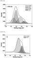
- 238000004833 X-ray photoelectron spectroscopy Methods 0.000 description 11
- 229910052598 goethite Inorganic materials 0.000 description 11
- 125000004429 atom Chemical group 0.000 description 10
- 239000013068 control sample Substances 0.000 description 10
- XLYOFNOQVPJJNP-UHFFFAOYSA-M hydroxide Chemical compound [OH-] XLYOFNOQVPJJNP-UHFFFAOYSA-M 0.000 description 10
- 239000000243 solution Substances 0.000 description 10
- 238000012360 testing method Methods 0.000 description 10
- VMHLLURERBWHNL-UHFFFAOYSA-M Sodium acetate Chemical compound [Na+].CC([O-])=O VMHLLURERBWHNL-UHFFFAOYSA-M 0.000 description 9
- 235000013980 iron oxide Nutrition 0.000 description 9
- 239000002245 particle Substances 0.000 description 9
- 239000000843 powder Substances 0.000 description 9
- 238000000634 powder X-ray diffraction Methods 0.000 description 9
- 238000005033 Fourier transform infrared spectroscopy Methods 0.000 description 8
- 229910021578 Iron(III) chloride Inorganic materials 0.000 description 8
- 230000008859 change Effects 0.000 description 8
- 238000001095 inductively coupled plasma mass spectrometry Methods 0.000 description 8
- RBTARNINKXHZNM-UHFFFAOYSA-K iron trichloride Chemical compound Cl[Fe](Cl)Cl RBTARNINKXHZNM-UHFFFAOYSA-K 0.000 description 8
- 238000002250 neutron powder diffraction Methods 0.000 description 8
- 238000001069 Raman spectroscopy Methods 0.000 description 6
- 238000004166 bioassay Methods 0.000 description 6
- 238000002425 crystallisation Methods 0.000 description 6
- 239000011521 glass Substances 0.000 description 6
- 238000002156 mixing Methods 0.000 description 6
- 239000000203 mixture Substances 0.000 description 6
- SCVFZCLFOSHCOH-UHFFFAOYSA-M potassium acetate Chemical compound [K+].CC([O-])=O SCVFZCLFOSHCOH-UHFFFAOYSA-M 0.000 description 6
- 238000006722 reduction reaction Methods 0.000 description 6
- 238000004098 selected area electron diffraction Methods 0.000 description 6
- 239000001632 sodium acetate Substances 0.000 description 6
- 235000017281 sodium acetate Nutrition 0.000 description 6
- 239000000758 substrate Substances 0.000 description 6
- 229910017251 AsO4 Inorganic materials 0.000 description 5
- 231100000674 Phytotoxicity Toxicity 0.000 description 5
- 238000009395 breeding Methods 0.000 description 5
- 230000001488 breeding effect Effects 0.000 description 5
- 238000001816 cooling Methods 0.000 description 5
- 230000000694 effects Effects 0.000 description 5
- WOSISLOTWLGNKT-UHFFFAOYSA-L iron(2+);dichloride;hexahydrate Chemical compound O.O.O.O.O.O.Cl[Fe]Cl WOSISLOTWLGNKT-UHFFFAOYSA-L 0.000 description 5
- 230000002194 synthesizing effect Effects 0.000 description 5
- 238000003991 Rietveld refinement Methods 0.000 description 4
- 230000008025 crystallization Effects 0.000 description 4
- 230000003100 immobilizing effect Effects 0.000 description 4
- 229910052500 inorganic mineral Inorganic materials 0.000 description 4
- 239000011707 mineral Substances 0.000 description 4
- 239000002159 nanocrystal Substances 0.000 description 4
- 239000002086 nanomaterial Substances 0.000 description 4
- 238000011946 reduction process Methods 0.000 description 4
- USFZMSVCRYTOJT-UHFFFAOYSA-N Ammonium acetate Chemical compound N.CC(O)=O USFZMSVCRYTOJT-UHFFFAOYSA-N 0.000 description 3
- 239000005695 Ammonium acetate Substances 0.000 description 3
- 238000001157 Fourier transform infrared spectrum Methods 0.000 description 3
- 239000002671 adjuvant Substances 0.000 description 3
- 235000019257 ammonium acetate Nutrition 0.000 description 3
- 229940043376 ammonium acetate Drugs 0.000 description 3
- 239000000356 contaminant Substances 0.000 description 3
- 238000011109 contamination Methods 0.000 description 3
- 238000002447 crystallographic data Methods 0.000 description 3
- 238000009826 distribution Methods 0.000 description 3
- 238000000605 extraction Methods 0.000 description 3
- 150000002500 ions Chemical class 0.000 description 3
- 238000003475 lamination Methods 0.000 description 3
- 230000037361 pathway Effects 0.000 description 3
- 235000011056 potassium acetate Nutrition 0.000 description 3
- 241000894007 species Species 0.000 description 3
- 238000001228 spectrum Methods 0.000 description 3
- 238000005406 washing Methods 0.000 description 3
- 229910006299 γ-FeOOH Inorganic materials 0.000 description 3
- 241001427559 Collembola Species 0.000 description 2
- 241000196324 Embryophyta Species 0.000 description 2
- LFQSCWFLJHTTHZ-UHFFFAOYSA-N Ethanol Chemical compound CCO LFQSCWFLJHTTHZ-UHFFFAOYSA-N 0.000 description 2
- 238000002441 X-ray diffraction Methods 0.000 description 2
- 238000007792 addition Methods 0.000 description 2
- 238000005452 bending Methods 0.000 description 2
- 229910001593 boehmite Inorganic materials 0.000 description 2
- 229910052599 brucite Inorganic materials 0.000 description 2
- 150000007942 carboxylates Chemical class 0.000 description 2
- 230000003247 decreasing effect Effects 0.000 description 2
- MTHSVFCYNBDYFN-UHFFFAOYSA-N diethylene glycol Chemical compound OCCOCCO MTHSVFCYNBDYFN-UHFFFAOYSA-N 0.000 description 2
- 238000002524 electron diffraction data Methods 0.000 description 2
- 230000006870 function Effects 0.000 description 2
- 229910052595 hematite Inorganic materials 0.000 description 2
- 239000011019 hematite Substances 0.000 description 2
- 230000007062 hydrolysis Effects 0.000 description 2
- 238000006460 hydrolysis reaction Methods 0.000 description 2
- FAHBNUUHRFUEAI-UHFFFAOYSA-M hydroxidooxidoaluminium Chemical compound O[Al]=O FAHBNUUHRFUEAI-UHFFFAOYSA-M 0.000 description 2
- 238000011065 in-situ storage Methods 0.000 description 2
- VBMVTYDPPZVILR-UHFFFAOYSA-N iron(2+);oxygen(2-) Chemical class [O-2].[Fe+2] VBMVTYDPPZVILR-UHFFFAOYSA-N 0.000 description 2
- LIKBJVNGSGBSGK-UHFFFAOYSA-N iron(3+);oxygen(2-) Chemical compound [O-2].[O-2].[O-2].[Fe+3].[Fe+3] LIKBJVNGSGBSGK-UHFFFAOYSA-N 0.000 description 2
- VCJMYUPGQJHHFU-UHFFFAOYSA-N iron(III) nitrate Inorganic materials [Fe+3].[O-][N+]([O-])=O.[O-][N+]([O-])=O.[O-][N+]([O-])=O VCJMYUPGQJHHFU-UHFFFAOYSA-N 0.000 description 2
- 238000004519 manufacturing process Methods 0.000 description 2
- 239000003607 modifier Substances 0.000 description 2
- 230000000877 morphologic effect Effects 0.000 description 2
- 230000001590 oxidative effect Effects 0.000 description 2
- 238000000746 purification Methods 0.000 description 2
- 230000035484 reaction time Effects 0.000 description 2
- 239000000523 sample Substances 0.000 description 2
- UWHCKJMYHZGTIT-UHFFFAOYSA-N tetraethylene glycol Chemical compound OCCOCCOCCOCCO UWHCKJMYHZGTIT-UHFFFAOYSA-N 0.000 description 2
- 238000002411 thermogravimetry Methods 0.000 description 2
- 230000009466 transformation Effects 0.000 description 2
- 238000001106 transmission high energy electron diffraction data Methods 0.000 description 2
- ZIBGPFATKBEMQZ-UHFFFAOYSA-N triethylene glycol Chemical compound OCCOCCOCCO ZIBGPFATKBEMQZ-UHFFFAOYSA-N 0.000 description 2
- 241000686720 Allonychiurus Species 0.000 description 1
- 235000011332 Brassica juncea Nutrition 0.000 description 1
- 235000014700 Brassica juncea var napiformis Nutrition 0.000 description 1
- 125000006519 CCH3 Chemical group 0.000 description 1
- 241001465754 Metazoa Species 0.000 description 1
- 238000003723 Smelting Methods 0.000 description 1
- CUPCBVUMRUSXIU-UHFFFAOYSA-N [Fe].OOO Chemical compound [Fe].OOO CUPCBVUMRUSXIU-UHFFFAOYSA-N 0.000 description 1
- 238000000367 ab initio method Methods 0.000 description 1
- 238000010521 absorption reaction Methods 0.000 description 1
- 230000002378 acidificating effect Effects 0.000 description 1
- 150000001450 anions Chemical class 0.000 description 1
- GCPXMJHSNVMWNM-UHFFFAOYSA-N arsenous acid Chemical compound O[As](O)O GCPXMJHSNVMWNM-UHFFFAOYSA-N 0.000 description 1
- 230000008901 benefit Effects 0.000 description 1
- 239000011230 binding agent Substances 0.000 description 1
- 238000011953 bioanalysis Methods 0.000 description 1
- 238000004173 biogeochemical cycle Methods 0.000 description 1
- 239000000090 biomarker Substances 0.000 description 1
- 230000000711 cancerogenic effect Effects 0.000 description 1
- 229910052799 carbon Inorganic materials 0.000 description 1
- 231100000357 carcinogen Toxicity 0.000 description 1
- 239000003183 carcinogenic agent Substances 0.000 description 1
- 150000001768 cations Chemical class 0.000 description 1
- 239000000919 ceramic Substances 0.000 description 1
- 238000000546 chi-square test Methods 0.000 description 1
- 230000001684 chronic effect Effects 0.000 description 1
- 239000000470 constituent Substances 0.000 description 1
- 238000007796 conventional method Methods 0.000 description 1
- 238000005137 deposition process Methods 0.000 description 1
- 238000011161 development Methods 0.000 description 1
- 238000004455 differential thermal analysis Methods 0.000 description 1
- 238000001678 elastic recoil detection analysis Methods 0.000 description 1
- 238000002003 electron diffraction Methods 0.000 description 1
- 230000007613 environmental effect Effects 0.000 description 1
- 238000011066 ex-situ storage Methods 0.000 description 1
- 238000002474 experimental method Methods 0.000 description 1
- 230000036541 health Effects 0.000 description 1
- 230000005802 health problem Effects 0.000 description 1
- 239000012510 hollow fiber Substances 0.000 description 1
- 229910052739 hydrogen Inorganic materials 0.000 description 1
- 239000001257 hydrogen Substances 0.000 description 1
- 150000004679 hydroxides Chemical class 0.000 description 1
- 238000000155 in situ X-ray diffraction Methods 0.000 description 1
- 239000004615 ingredient Substances 0.000 description 1
- 230000009878 intermolecular interaction Effects 0.000 description 1
- 230000001418 larval effect Effects 0.000 description 1
- 239000003446 ligand Substances 0.000 description 1
- 238000012423 maintenance Methods 0.000 description 1
- 238000005259 measurement Methods 0.000 description 1
- 238000010907 mechanical stirring Methods 0.000 description 1
- 229910044991 metal oxide Inorganic materials 0.000 description 1
- 150000004706 metal oxides Chemical class 0.000 description 1
- 238000005272 metallurgy Methods 0.000 description 1
- 238000005065 mining Methods 0.000 description 1
- 230000004048 modification Effects 0.000 description 1
- 238000012986 modification Methods 0.000 description 1
- 239000011368 organic material Substances 0.000 description 1
- 239000005416 organic matter Substances 0.000 description 1
- 125000004430 oxygen atom Chemical group O* 0.000 description 1
- 239000002574 poison Substances 0.000 description 1
- 231100000614 poison Toxicity 0.000 description 1
- 238000004917 polyol method Methods 0.000 description 1
- 239000011148 porous material Substances 0.000 description 1
- 238000002360 preparation method Methods 0.000 description 1
- 230000009467 reduction Effects 0.000 description 1
- 239000011347 resin Substances 0.000 description 1
- 229920005989 resin Polymers 0.000 description 1
- 238000005001 rutherford backscattering spectroscopy Methods 0.000 description 1
- 229910052708 sodium Inorganic materials 0.000 description 1
- 239000011734 sodium Substances 0.000 description 1
- 238000003860 storage Methods 0.000 description 1
- 238000006467 substitution reaction Methods 0.000 description 1
- 238000001308 synthesis method Methods 0.000 description 1
- 231100000331 toxic Toxicity 0.000 description 1
- 230000002588 toxic effect Effects 0.000 description 1
- 231100000419 toxicity Toxicity 0.000 description 1
- 230000001988 toxicity Effects 0.000 description 1
- 238000004627 transmission electron microscopy Methods 0.000 description 1
- 229910006540 α-FeOOH Inorganic materials 0.000 description 1
- 229910003153 β-FeOOH Inorganic materials 0.000 description 1
Images
















Classifications
-
- B—PERFORMING OPERATIONS; TRANSPORTING
- B09—DISPOSAL OF SOLID WASTE; RECLAMATION OF CONTAMINATED SOIL
- B09C—RECLAMATION OF CONTAMINATED SOIL
- B09C1/00—Reclamation of contaminated soil
- B09C1/08—Reclamation of contaminated soil chemically
-
- B—PERFORMING OPERATIONS; TRANSPORTING
- B01—PHYSICAL OR CHEMICAL PROCESSES OR APPARATUS IN GENERAL
- B01J—CHEMICAL OR PHYSICAL PROCESSES, e.g. CATALYSIS OR COLLOID CHEMISTRY; THEIR RELEVANT APPARATUS
- B01J20/00—Solid sorbent compositions or filter aid compositions; Sorbents for chromatography; Processes for preparing, regenerating or reactivating thereof
- B01J20/22—Solid sorbent compositions or filter aid compositions; Sorbents for chromatography; Processes for preparing, regenerating or reactivating thereof comprising organic material
- B01J20/223—Solid sorbent compositions or filter aid compositions; Sorbents for chromatography; Processes for preparing, regenerating or reactivating thereof comprising organic material containing metals, e.g. organo-metallic compounds, coordination complexes
-
- C—CHEMISTRY; METALLURGY
- C09—DYES; PAINTS; POLISHES; NATURAL RESINS; ADHESIVES; COMPOSITIONS NOT OTHERWISE PROVIDED FOR; APPLICATIONS OF MATERIALS NOT OTHERWISE PROVIDED FOR
- C09C—TREATMENT OF INORGANIC MATERIALS, OTHER THAN FIBROUS FILLERS, TO ENHANCE THEIR PIGMENTING OR FILLING PROPERTIES ; PREPARATION OF CARBON BLACK ; PREPARATION OF INORGANIC MATERIALS WHICH ARE NO SINGLE CHEMICAL COMPOUNDS AND WHICH ARE MAINLY USED AS PIGMENTS OR FILLERS
- C09C1/00—Treatment of specific inorganic materials other than fibrous fillers; Preparation of carbon black
- C09C1/22—Compounds of iron
-
- B—PERFORMING OPERATIONS; TRANSPORTING
- B01—PHYSICAL OR CHEMICAL PROCESSES OR APPARATUS IN GENERAL
- B01J—CHEMICAL OR PHYSICAL PROCESSES, e.g. CATALYSIS OR COLLOID CHEMISTRY; THEIR RELEVANT APPARATUS
- B01J20/00—Solid sorbent compositions or filter aid compositions; Sorbents for chromatography; Processes for preparing, regenerating or reactivating thereof
- B01J20/02—Solid sorbent compositions or filter aid compositions; Sorbents for chromatography; Processes for preparing, regenerating or reactivating thereof comprising inorganic material
- B01J20/0203—Solid sorbent compositions or filter aid compositions; Sorbents for chromatography; Processes for preparing, regenerating or reactivating thereof comprising inorganic material comprising compounds of metals not provided for in B01J20/04
- B01J20/0225—Compounds of Fe, Ru, Os, Co, Rh, Ir, Ni, Pd, Pt
- B01J20/0229—Compounds of Fe
-
- B—PERFORMING OPERATIONS; TRANSPORTING
- B01—PHYSICAL OR CHEMICAL PROCESSES OR APPARATUS IN GENERAL
- B01J—CHEMICAL OR PHYSICAL PROCESSES, e.g. CATALYSIS OR COLLOID CHEMISTRY; THEIR RELEVANT APPARATUS
- B01J20/00—Solid sorbent compositions or filter aid compositions; Sorbents for chromatography; Processes for preparing, regenerating or reactivating thereof
- B01J20/02—Solid sorbent compositions or filter aid compositions; Sorbents for chromatography; Processes for preparing, regenerating or reactivating thereof comprising inorganic material
- B01J20/06—Solid sorbent compositions or filter aid compositions; Sorbents for chromatography; Processes for preparing, regenerating or reactivating thereof comprising inorganic material comprising oxides or hydroxides of metals not provided for in group B01J20/04
-
- B—PERFORMING OPERATIONS; TRANSPORTING
- B01—PHYSICAL OR CHEMICAL PROCESSES OR APPARATUS IN GENERAL
- B01J—CHEMICAL OR PHYSICAL PROCESSES, e.g. CATALYSIS OR COLLOID CHEMISTRY; THEIR RELEVANT APPARATUS
- B01J20/00—Solid sorbent compositions or filter aid compositions; Sorbents for chromatography; Processes for preparing, regenerating or reactivating thereof
- B01J20/28—Solid sorbent compositions or filter aid compositions; Sorbents for chromatography; Processes for preparing, regenerating or reactivating thereof characterised by their form or physical properties
- B01J20/28002—Solid sorbent compositions or filter aid compositions; Sorbents for chromatography; Processes for preparing, regenerating or reactivating thereof characterised by their form or physical properties characterised by their physical properties
- B01J20/28004—Sorbent size or size distribution, e.g. particle size
- B01J20/28007—Sorbent size or size distribution, e.g. particle size with size in the range 1-100 nanometers, e.g. nanosized particles, nanofibers, nanotubes, nanowires or the like
-
- B—PERFORMING OPERATIONS; TRANSPORTING
- B01—PHYSICAL OR CHEMICAL PROCESSES OR APPARATUS IN GENERAL
- B01J—CHEMICAL OR PHYSICAL PROCESSES, e.g. CATALYSIS OR COLLOID CHEMISTRY; THEIR RELEVANT APPARATUS
- B01J20/00—Solid sorbent compositions or filter aid compositions; Sorbents for chromatography; Processes for preparing, regenerating or reactivating thereof
- B01J20/30—Processes for preparing, regenerating, or reactivating
- B01J20/3085—Chemical treatments not covered by groups B01J20/3007 - B01J20/3078
-
- C—CHEMISTRY; METALLURGY
- C01—INORGANIC CHEMISTRY
- C01G—COMPOUNDS CONTAINING METALS NOT COVERED BY SUBCLASSES C01D OR C01F
- C01G49/00—Compounds of iron
- C01G49/02—Oxides; Hydroxides
-
- B—PERFORMING OPERATIONS; TRANSPORTING
- B01—PHYSICAL OR CHEMICAL PROCESSES OR APPARATUS IN GENERAL
- B01J—CHEMICAL OR PHYSICAL PROCESSES, e.g. CATALYSIS OR COLLOID CHEMISTRY; THEIR RELEVANT APPARATUS
- B01J2220/00—Aspects relating to sorbent materials
- B01J2220/40—Aspects relating to the composition of sorbent or filter aid materials
- B01J2220/46—Materials comprising a mixture of inorganic and organic materials
-
- C—CHEMISTRY; METALLURGY
- C01—INORGANIC CHEMISTRY
- C01P—INDEXING SCHEME RELATING TO STRUCTURAL AND PHYSICAL ASPECTS OF SOLID INORGANIC COMPOUNDS
- C01P2002/00—Crystal-structural characteristics
- C01P2002/20—Two-dimensional structures
-
- C—CHEMISTRY; METALLURGY
- C01—INORGANIC CHEMISTRY
- C01P—INDEXING SCHEME RELATING TO STRUCTURAL AND PHYSICAL ASPECTS OF SOLID INORGANIC COMPOUNDS
- C01P2002/00—Crystal-structural characteristics
- C01P2002/70—Crystal-structural characteristics defined by measured X-ray, neutron or electron diffraction data
- C01P2002/72—Crystal-structural characteristics defined by measured X-ray, neutron or electron diffraction data by d-values or two theta-values, e.g. as X-ray diagram
-
- C—CHEMISTRY; METALLURGY
- C01—INORGANIC CHEMISTRY
- C01P—INDEXING SCHEME RELATING TO STRUCTURAL AND PHYSICAL ASPECTS OF SOLID INORGANIC COMPOUNDS
- C01P2002/00—Crystal-structural characteristics
- C01P2002/70—Crystal-structural characteristics defined by measured X-ray, neutron or electron diffraction data
- C01P2002/76—Crystal-structural characteristics defined by measured X-ray, neutron or electron diffraction data by a space-group or by other symmetry indications
-
- C—CHEMISTRY; METALLURGY
- C01—INORGANIC CHEMISTRY
- C01P—INDEXING SCHEME RELATING TO STRUCTURAL AND PHYSICAL ASPECTS OF SOLID INORGANIC COMPOUNDS
- C01P2002/00—Crystal-structural characteristics
- C01P2002/70—Crystal-structural characteristics defined by measured X-ray, neutron or electron diffraction data
- C01P2002/77—Crystal-structural characteristics defined by measured X-ray, neutron or electron diffraction data by unit-cell parameters, atom positions or structure diagrams
-
- C—CHEMISTRY; METALLURGY
- C01—INORGANIC CHEMISTRY
- C01P—INDEXING SCHEME RELATING TO STRUCTURAL AND PHYSICAL ASPECTS OF SOLID INORGANIC COMPOUNDS
- C01P2002/00—Crystal-structural characteristics
- C01P2002/70—Crystal-structural characteristics defined by measured X-ray, neutron or electron diffraction data
- C01P2002/78—Crystal-structural characteristics defined by measured X-ray, neutron or electron diffraction data by stacking-plane distances or stacking sequences
-
- C—CHEMISTRY; METALLURGY
- C01—INORGANIC CHEMISTRY
- C01P—INDEXING SCHEME RELATING TO STRUCTURAL AND PHYSICAL ASPECTS OF SOLID INORGANIC COMPOUNDS
- C01P2004/00—Particle morphology
- C01P2004/01—Particle morphology depicted by an image
- C01P2004/04—Particle morphology depicted by an image obtained by TEM, STEM, STM or AFM
-
- C—CHEMISTRY; METALLURGY
- C01—INORGANIC CHEMISTRY
- C01P—INDEXING SCHEME RELATING TO STRUCTURAL AND PHYSICAL ASPECTS OF SOLID INORGANIC COMPOUNDS
- C01P2004/00—Particle morphology
- C01P2004/20—Particle morphology extending in two dimensions, e.g. plate-like
- C01P2004/24—Nanoplates, i.e. plate-like particles with a thickness from 1-100 nanometer
Definitions
- the present disclosure relates to layered ferric rust and iron hydroxide nanoparticles including the same, and more particularly, to layered ferric rust having a new crystal structure due to anion organic matter intercalated between layered structures of iron oxide/ferric hydroxide and iron hydroxide nanoparticles including the layered ferric rust.
- Iron hydroxide is an abundant mineral that makes up 4 % of the Earth's crust, plays an important role in biogeochemical cycles and ecosystem maintenance, and is attracting attention in various fields such as metallurgy, water purification, energy conversion and storage.
- Naturally occurring iron hydroxide includes ferrihydrite, ferric hydroxide (FeOOH) polymorphs (goethite, akaganetie, lepidocorcite, and feroxyhyte), and green rust (types 1 and 2).
- an iron hydroxide material with a new crystal structure may provide important information about the iron oxide crystallization process beyond basic understanding and technical impact thereof.
- Arsenic is an ingredient harmful to the human body and has been used as a material for poison in the past. Surprisingly, such arsenic is a substance that is commonly encountered in the surroundings. Arsenic is not only produced by production activities such as mining and smelting, but also occurs naturally.
- an adsorbent prepared by mixing iron oxide, iron oxyhydroxide, or a mixture thereof known as an arsenic-adsorbing material with a cation-selective binder resin is used to increase mechanical strength and arsenic adsorption efficiency.
- the present disclosure has been made in view of the above problems, and it is an object of the present disclosure to provide layered ferric rust having a novel crystal structure in which organic anions are intercalated between nanoplatelet layers to have a relatively wide interlayer spacing compared to a nanoparticle size, and iron hydroxide nanoparticles including the layered ferric rust.
- layered ferric rust having a novel crystal structure that satisfies conditions (a) to (c) below:
- Atomic coordinates and equivalent isotropic displacement parameters in a lattice of the layered ferric rust may satisfy Table 1 below: [Table 1] Element x y z B eq Occ. Fe(1) 0.4096(19) 0.4207(15) 0.293(7) 1 1 Fe(2) 0.409(2) 0.4391(16) 0.606(7) 1 1 C(1) 0.318(2) 0.669(5) 0.455(5) 2 1 C(2) 0.220(3) 0.789(5) 0.411(7) 2 1 O(1) 0.507(3) 0.239(8) 0.252(10) 2 1 O(2) 0.2716(16) 0.638(4) 0.577(5) 2 1 O(3) 0.899(5) 0.451(7) 0.298(17) 2 0.75 O(4) 0.426(4) 0.521(6) 0.104(17) 2 0.75 O(5) 0.424(3) 0.593(7) 0.371(5) 2 1 O(6) 0.258(2) 0.257(8) 0.637(10) 2 1 O(7) 0.563(3) 0.044(5) 0.322(5) 2 1 O(8) 0.584(2) 0.320(9)
- the layered ferric rust may be represented by Chemical Formula 1 below: [Chemical Formula 1] FeO x C y H z , wherein x is a prime number between 3 and 3.5 (3 ⁇ x ⁇ 3.5), y is a prime number between 0.67 to 1 (0.67 ⁇ y ⁇ 1), and z is a prime number between 1.94 to 3.5 (1.94 ⁇ z ⁇ 3.5).
- the layered ferric rust may include two or more nanoplatelet layers including one or more FeOe octahedral structures; and organic anions intercalated between the two or more nanoplatelet layers, wherein, in the two or more nanoplatelet layers, an interlayer spacing is created by the organic anions.
- the nanoplatelets and the organic anions may be bonded to each other by bidentate bridging.
- the nanoplatelets may include corner-sharing and edge-sharing of the adjacent FeOe octahedral structures in a zigzag pattern by the organic anions.
- the number of the two or more nanoplatelet layers may be 2 to 16.
- the nanoplatelets may include iron(III) oxide-hydroxide (FeOOH).
- the organic anions may include an acetate (CH 3 COO - )-based compound.
- iron hydroxide nanoparticles including the layered ferric rust according to an embodiment of the present disclosure.
- the iron hydroxide nanoparticles may be included in at least one of a pollutant adsorbent, a battery catalyst, an oxygen evolution reaction (OER) catalyst, a thermal therapy material, bioplastics, a construction material, a pigment, and a dye.
- a pollutant adsorbent e.g., a battery catalyst
- OER oxygen evolution reaction
- an arsenic adsorbent including organic-inorganic composite iron hydroxide nanoparticles, wherein the organic-inorganic composite iron hydroxide nanoparticles include two or more nanoplatelet layers including one or more FeOe octahedral structures; and organic ligands intercalated between the two or more nanoplatelet layers, wherein the organic-inorganic composite iron hydroxide nanoparticles adsorb arsenic by chemisorption by surfaces of the nanoplatelets and by electrostatic intercalation by an interlayer spacing between the nanoplatelets.
- the interlayer spacing of the two or more nanoplatelet layers may be 1.14 nm to 1.19 nm.
- the nanoplatelets and the organic ligands may be bonded to each other by bidentate bridging.
- the adjacent FeOe octahedral structures may be corner-shared and edge-shared in a zigzag pattern by the organic ligands.
- the number of the two or more nanoplatelet layers may be 2 to 16.
- the nanoplatelets may include iron(III) oxide-hydroxide (FeOOH).
- the organic ligands may include an acetate (CH 3 COO - )-based compound.
- the arsenic may be included in soil.
- hydroxide is mainly formed through a particle-directed attachment process and grown through colloidal assembly of nano-scale building blocks.
- the particle-directed attachment process is known as a new growth model that is related to anisotropy or formation of a complex structure with an organic material.
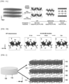
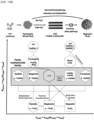
- FIGS. 1A and 1B schematically show layered ferric rust (LFR) according to an embodiment of the present disclosure, which a novel crystal structure of iron hydroxide, and conventional crystal structures of iron hydroxide.
- LFR layered ferric rust
- Layered ferric rust is a novel crystal structure material having a relatively wide interlayer spacing compared to the size of particles due to acetate intercalated between layers of ferric hydroxide, and acetate, which is an organic anion, may form a layered ferric rust (LFR) structure by distorting the arrangement of FeO 6 octahedrons and creating a lamination of hydroxide layers.
- LFR layered ferric rust
- water molecules added in excess in the process of synthesizing hydroxide may play a decisive role in formation of acetate and a novel crystal structure by participating in a dehydration process during a chemical reaction of converting metastable ferrihydrite into stable magnetite.
- the layered ferric rust according to an embodiment of the present disclosure has a novel crystal structure different from lepidocrocite and green rust having the known ferric hydroxide layered structure.
- the layered ferric rust according to an embodiment of the present disclosure has a novel crystal structure that satisfies the following conditions (a) to (c).
- a means one side of a unit cell in the [100] axial direction
- c means one side of a unit cell in the [001] axial direction
- ⁇ means an angle between the ac plane and the b axis.
- the crystal structure is the internal structure of six crystal systems, and the properties of a material vary depending on the crystal structure thereof.
- the layered ferric rust according to an embodiment of the present disclosure has a novel crystal structure different from the crystal structures of existing FeOOH polymorphs through synchrotron HRPD and Raman analysis.
- the layered ferric rust according to an embodiment of the present disclosure preferably has a novel crystal structure that satisfying the following conditions: a crystal system belongs to a monoclinic system, a space group belongs to Pn (No.
- the volume means the volume of a unit cell
- Z means proton number
- the formula weight means a sum of the atomic weights of elements included in a chemical formula
- the density means a value obtained through weight/volume - TGA measurement
- the temperature means a measurement temperature in synchrotron high-resolution powder neutron diffraction analysis
- the wavelength means the wavelength of X-ray used in synchrotron high-resolution powder neutron diffraction analysis.
- XRD is measured by scanning a diffraction angle (2 ⁇ ) while an X-ray source and a detector move along the circumference.
- the 2 ⁇ range means a range to be scanned
- step scan increment means increment of an incident angle
- an R-factor is a reliable factor for refinement results and expresses the difference between a calculated value and a measured value in %, indicating the reliability of the calculated value.
- R p may be calculated by Equation 1 below
- R wp may be calculated by Equation 2 below
- R exp may be calculated by Equation 3 below
- R bragg may be calculated by Equation 4 below.
- the electron density When measuring the electron density of a sample with XRD, the electron density is actually distorted in a three-dimensional direction rather than a sphere due to the bonding or arrangement of atoms.
- the electron density In powder XRD, the electron density is assumed to be spherical and the extent to which the electron density diverges from the original is calculated.
- B is a thermal factor
- eq is a variable assuming a spherical shape.
- G.O.F. is good of fitness and a reduced chi-square test, and means a goodness-of-fit test that determines whether an observed ratio value is the same as an expected value.
- Table 2 shows the crystallographic data of LFR obtained from synchrotron high-resolution powder neutron diffraction analysis, including crystal systems, space groups, the length of each side of a unit cell, angle, volume, molecular weight, density, and information used for analysis, and the crystallographic data shows the reliability of the above analysis.
- Atomic coordinates and equivalent isotropic displacement parameters in the lattice of the layered ferric rust according to an embodiment of the present disclosure may satisfy Table 1 below.
- Table 1 Element x y z B eq Occ. Fe(1) 0.4096(19) 0.4207(15) 0.293(7) 1 1 Fe(2) 0.409(2) 0.4391(16) 0.606(7) 1 1 C(1) 0.318(2) 0.669(5) 0.455(5) 2 1 C(2) 0.220(3) 0.789(5) 0.411(7) 2 1 O(1) 0.507(3) 0.239(8) 0.252(10) 2 1 O(2) 0.2716(16) 0.638(4) 0.577(5) 2 1 O(3) 0.899(5) 0.451(7) 0.298(17) 2 0.75 O(4) 0.426(4) 0.521(6) 0.104(17) 2 0.75 O(5) 0.424(3) 0.593(7) 0.371(5) 2 1 O(6) 0.258(2) 0.257(8) 0.637(10) 2 1 O(7) 0.563(3) 0.044(5) 0.322(5) 2 1 O(8) 0.5
- x, y, and z represent the coordinates of each atom in a unit cell
- Occ. is site occupancy, and means site occupancy (e.g., when one exists, it means 1) in which the corresponding atom exists at an atomic site in a unit cell.
- the number in parentheses is the standard deviation of a result value, and 0.4096(19) may mean 0.4096 ⁇ 0.019.
- Occ. is occupancy (site occupancy), and is a value indicating a degree to which atoms occupy a unit cell when one oxygen atom is assumed to be 1.
- Table 1 shows the coordinates of all atoms in a unit cell in 3D space.
- the layered ferric rust according to an embodiment of the present disclosure may be represented by Chemical Formula 1 below. [Chemical Formula 1] FeO x C y H z
- x is a prime number between 3 and 3.5 (3 ⁇ x ⁇ 3.5)
- y is a prime number between 0.67 to 1 (0.67 ⁇ y ⁇ 1)
- z is a prime number between 1.94 to 3.5 (1.94 ⁇ z ⁇ 3.5).
- the layered ferric rust according to an embodiment of the present disclosure may be FeO 3.5 CH 3.5 or Fe 2 O 4 H 2 ⁇ (CH 3 COO) ⁇ H 2 O.
- the layered ferric rust according to an embodiment of the present disclosure may be synthesized by a particle-directed deposition process and may have a novel crystal structure due to organic anions intercalated between two or more nanoplatelet layers (e.g., ferric hydroxide).
- nanoplatelet layers e.g., ferric hydroxide
- organic anion molecules grafted onto building blocks are closely related to intermolecular interaction in an assembly process
- organic anions e.g., acetate
- hydroxide e.g., ferric hydroxide
- ⁇ -FeOOH and green rust may have boehmite arranged in a zigzag arrangement along the ac plane and brucite having a planar FeO 3 (OH) 3 arrangement along the ab plane.
- an FeO 6 octahedral structure is connected by edge-sharing in the a-axis direction by organic anions, and in the c-axis direction, edge-sharing is broken and corner-sharing is formed in the organic anions 121.
- the layered ferric rust has a completely different crystal structure.
- FIG. 2 schematically shows layered ferric rust according to an embodiment of the present disclosure
- FIG. 3 schematically shows an example of nanoplatelets and organic anions included in layered ferric rust according to an embodiment of the present disclosure.
- the layered ferric rust according to an embodiment of the present disclosure includes two or more nanoplatelet layers 110 including one or more FeOe octahedral structures 111 and the organic anions 121 intercalated between the two or more nanoplatelet layers 110. Due to the organic anions 121, the two or more nanoplatelet layers 110 have an interlayer spacing 120, which is a distance between the layers.
- the layered ferric rust since the organic anions 121 are intercalated between the nanoplatelet layers 110, the layered ferric rust may have the relatively wide interlayer spacing 120 compared to the size of nanoparticles.
- the layered ferric rust has a crystal structure different from other FeOOH (green rust, lepidocrocite) materials having a conventional layered structure, by discovering new pathways and intermediates that form Fe 3 O 4 , contaminants may be adsorbed and removed by using the wide interlayer spacing 120, and the layered ferric rust may be used as a battery catalyst.
- the nanoplatelets 110 and the organic anions 121 may be connected by bidentate bridging. Accordingly, the nanoplatelets 110 may have a zigzag structure due to edge-sharing of the adjacent FeOe octahedral structures 111 and corner-sharing by the organic anions 121.
- the a-axis direction is similar to other FeOOH having a conventional layered structure due to edge-sharing of Fe atoms in the FeOe octahedrons.
- the LFR has a wide interlayer spacing due to distortion caused by the organic anions 121.
- edge-sharing is broken and Fe atoms are attached by corner-sharing, the LFR may have a crystal structure different from other FeOOH having a conventional layered structure. The combined structure will be described in more detail in FIG. 3 .
- the interlayer spacing 120 of the two or more nanoplatelet layers 110 may be 1.14 nm to 1.19 nm.
- the number of the two or more nanoplatelet layers 110 is not particularly limited, but the number of the two or more nanoplatelet layers 110 may be preferably 2 to 16.
- the interlayer spacing 120 of the two or more nanoplatelet layers 110 and the number of the two or more nanoplatelet layers 110 are proportional to the synthesis time of LFR, as the heating time of a synthesis solution increases, the number of layers increases. After 8 hours, the speed at which the size of particles increases gradually slows down, and may reach a critical point at about 8 hours (average number of layers is 16).
- the nanoplatelets 110 may have a disk shape.
- the nanoplatelets 110 may include iron(III) oxide-hydroxide (FeOOH).
- the organic anions 121 may preferably include an acetate (CH 3 COO - )-based compound, without being limited thereto.
- the acetate-based compound may include at least one of sodium acetate, potassium acetate, and ammonium acetate.
- the layered ferric rust according to an embodiment of the present disclosure may be included in iron hydroxide nanoparticles according to an embodiment of the present disclosure.
- the iron hydroxide nanoparticles according to an embodiment of the present disclosure may be included in at least one of a pollutant adsorbent, a battery catalyst, an oxygen evolution reaction (OER) catalyst, a thermal therapy material, bioplastics, a construction material, a pigment, and a dye.
- a pollutant adsorbent e.g., a battery catalyst
- OER oxygen evolution reaction
- the wide interlayer spacing 120 is formed, and thus contaminants are more easily introduced into the wide interlayer spacing 120, thereby improving the removal efficiency of the contaminants.
- the nanoplatelets 110 are stacked in the b-axis direction in a state in which the octahedrons are twisted by the organic anions 121, the wide interlayer spacing 120 is formed, and thus large amounts of ions may be stored and transported in Na and Li batteries.
- the current density value thereof is higher than that of other FeOOH, thereby improving efficiency.
- FIG. 4 schematically shows a combined structure of nanoplatelets and organic anions included in layered ferric rust according to an embodiment of the present disclosure.
- the FeOe octahedral structures 111 of the layered ferric rust according to an embodiment of the present disclosure are linked to each other by edge-sharing in the a-axis direction.
- edge-sharing is broken at the organic anions 121 and corner-sharing is done.
- the nanoplatelets including the FeOe octahedral structures 111 may be formed on the ac plane and stacked in the b-axis direction to have the large interlayer spacing 120.
- a pair of corner-sharing FeO 6 octahedral structures 111 may form a zigzag layered arrangement with edge-sharing.
- the organic anions 121 may form a pair of the FeOe octahedral structures 111 by bidentate bridging, and at the same time, may participate as a component of the FeOe octahedral structures 111 with carboxylate thereof.
- the zigzag arrangement of the pairs of the FeOe octahedral structures 111 and the b-axis stacking induced by the organic anions 121 may determine the crystal structure of iron hydroxide.
- the layered ferric rust according to an embodiment of the present disclosure may have a completely different atomic arrangement compared to other iron hydroxides having a layered structure.
- Example 1 Synthesis of layered ferric rust having novel crystal structure
- LFR was obtained using a polyol method. Iron chloride hexahydrate (FeCl 3 ⁇ 6H 2 O) was used as an iron ion precursor, ethylene glycol (EG) was used as a reducing agent and a solvent, and sodium acetate (CH 3 COONa) and H 2 O were used as adjuvants to impart a hydroxyl group (OH-).
- FeCl 3 ⁇ 6H 2 O Iron chloride hexahydrate
- EG ethylene glycol
- CH 3 COONa sodium acetate
- H 2 O sodium acetate
- FIG. 5 shows a bright-field transmission electron microscope image of layered ferric rust according to an embodiment of the present disclosure
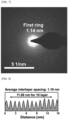
- FIG. 6 shows a scanning transmission electron microscope image of layered ferric rust according to an embodiment of the present disclosure taken at a low voltage of 80 kV
- FIG. 7 shows a selected-area electron diffraction analysis image of layered ferric rust according to an embodiment of the present disclosure.
- Fourier transform infrared analysis strong vibration of acetate molecules was observed. It was confirmed that acetate and iron were combined by bidentate bridging. Then, the coordination numbers of acetate and iron were confirmed.
- FIG. 8 is an intensity profile representing the interlayer spacing of layered ferric rust according to an embodiment of the present disclosure
- FIG. 9 includes graphs showing the surface properties of layered ferric rust according to an embodiment of the present disclosure
- FIGS. 10 to 14 are graphs showing the compositional analysis of layered ferric rust according to an embodiment of the present disclosure
- FIG. 15 shows a Fourier transform infrared spectrum representing the coordination of acetate of layered ferric rust according to an embodiment of the present disclosure
- FIG. 16 shows Raman analysis spectra of layered ferric rust according to an embodiment of the present disclosure and ferric hydroxide polymorphs.
- Table 3 shows the peak parameters of the Fourier transform infrared spectrum.
- the LFR has a different crystal structure.
- the crystal structure of the LFR was analyzed by performing high-resolution powder neutron diffraction using a synchrotron. Based on the analysis results, it can be seen that the crystal structure of the LFR is different from that of green rust and lepidocrocite, which have a layered structure among existing ferric hydroxides.
- FIG. 17 shows Rietveld analysis of synchrotron high-resolution powder neutron diffraction analysis that analyzes the crystal structure of layered ferric rust according to an embodiment of the present disclosure and an LFR crystal structure image thereof
- FIG. 18 is a graph showing the Rietveld analysis results of synchrotron high-resolution powder neutron diffraction analysis of layered ferric rust according to an embodiment of the present disclosure compared to a conventional crystal structure.
- the composition of the LFR was analyzed by in-situ X-ray diffraction, thermogravimetric analysis/differential thermal analysis, and Rutherford back scattering spectroscopy/elastic recoil detection analysis.
- the composition of each element is FeOOH ⁇ 0.5CH 3 COO, indicating that the LFR is a polymorph of ferric hydroxide.
- the layered ferric rust according to an embodiment of the present disclosure does not match the graph line of the conventional crystal structure, it can be seen that the layered ferric rust has a completely different crystal structure.
- FIG. 19A is a flowchart for explaining a method of preparing layered ferric rust according to an embodiment of the present disclosure
- FIG. 19B is a schematic diagram showing a process of forming an LFR crystal structure.
- the layered ferric rust according to an embodiment of the present disclosure may be prepared by the following method.
- the method of preparing the layered ferric rust according to an embodiment of the present disclosure includes the same components as the layered ferric rust according to an embodiment of the present disclosure, description of the same components will be omitted.
- step S 110 of mixing an iron ion precursor, a reducing agent, and a solvent to prepare a mixed solution is performed.
- Iron chloride hexahydrate (FeCl 3 ⁇ 6H 2 O) is preferably used as the iron ion precursor, without being limited thereto.
- the reducing agent may simultaneously act as a solvent.
- Ethylene glycol (EG) is preferably used as the reducing agent, without being limited thereto.
- the reducing agent may include at least one of ethylene glycol, di-ethylene glycol, tri-ethylene glycol, and tetra-ethylene glycol.
- the solvent may be water (H 2 O).
- a hydrolysis adjuvant may be further included, and the hydrolysis adjuvant may be sodium acetate (CH 3 COONa).
- step S120 of heating the mixed solution to grow layered ferric rust is performed.
- Step S120 of heating the mixed solution to grow layered ferric rust may include first heat treatment step S 121 of heating for 15 minutes to increase the temperature of the mixed solution to 200 °C and second heat treatment step S 122 of maintaining the temperature of the mixed solution at 200 °C for 8 hours.
- the first heat treatment step S 121 is a process of reaching the temperature of the second heat treatment step S122.
- the temperature of the mixed solution may be increased to 200 °C for 15 minutes.
- the second heat treatment step S 122 is a process of forming iron hydroxide FeOOH from ferrihydrite.
- crystals may be grown by heating the mixed solution at 200 °C for 8 hours.
- the reaction is initiated by heat treatment, and metastable iron hydroxide phases such as green rust and ferrihydrite may be formed to form thermodynamically stable iron oxides such as hematite and magnetite by an iron ion precursor.
- the iron ion precursor may react with acetate (organic anions) supplied from ethylene glycol as the reducing agent and hydroxyl ions supplied from the solvent (water) to form ferrihydrite.
- the layered ferric rust according to an embodiment of the present disclosure as an intermediate phase material may be prepared by adjusting the content of the solvent.
- iron hydroxide (FeOOH) is changed to magnetite through dehydration and reduction processes.
- hydroxyl groups OH -
- iron hydroxide FeOOH
- the dehydration and reduction processes that convert iron hydroxide (FeOOH) into magnetite are hindered, so that iron hydroxide remains as it is without being converted to magnetite.
- hydroxyl groups may be supplemented by adding a sufficient amount of water.
- the layered ferric rust according to an embodiment of the present disclosure may have a novel crystal structure different from the known ferric hydroxide layered structure of lepidocrocite and green rust.
- the ratio of hydroxyl group/iron may be controlled by the content of the solvent included in the mixed solution.
- the ratio of hydroxyl group/iron is an important factor in the process of converting iron hydroxide into magnetite.
- the ratio of hydroxyl group/iron (OH - /Fe) increases, hindering the dehydration and reduction reactions required to convert iron hydroxide (ferric oxyhydroxide) into magnetite.
- the content of the solvent may be 150 mmol to 400 mmol. When the content of the solvent is out of the above range, the LFR is not generated.
- the amount of the LFR produced may be controlled depending on the content of the solvent.
- the second heat treatment step S122 may include step S122-1 of forming ferrihydrite nanocrystals in the mixed solution, step S122-2 of forming nanoplatelets on the surface of the ferrihydrite nanocrystals, and step S122-3 of attaching two or more nanoplatelet layers at different angles to grow a layered ferric rust (LFR) crystal structure.
- step S122-1 of forming ferrihydrite nanocrystals in the mixed solution
- step S122-2 of forming nanoplatelets on the surface of the ferrihydrite nanocrystals
- step S122-3 of attaching two or more nanoplatelet layers at different angles to grow a layered ferric rust (LFR) crystal structure.
- ferrihydrite crystals having low crystallinity which are intermediates before conversion into magnetite, may be generated (S122-1).
- the nanoplatelet attachment method may be largely divided into three types: axial, lateral, and axial + lateral.
- the synthesis may be controlled according to the second heat treatment time.
- step S130 of cooling the heated mixed solution is performed.
- the process of generating LFR may be terminated.
- step S140 of washing the cooled mixed solution to obtain layered ferric rust according to an embodiment of the present disclosure is performed.
- LFR is synthesized through an intermediate in a stepwise transformation.
- thermodynamically stable iron oxide is generally synthesized through a metastable phase rather than directly synthesized from ions in a solution.
- ferrihydrite having low crystallinity is generated as an intermediate before LFR formation.
- 7 nm nanoplatelets in the form of particles having an interlayer spacing of 1.2 nm begin to form in the intermediate, and portions where adjacent nanoplatelets adhere at different angles are observed.
- Nanoplatelets are used as building blocks to grow the LFR. At this time, the LFR grows in both the thickness and stacking directions over time, and the size thereof is stabilized after about 8 hours.
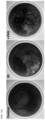
- FIG. 20 is a transmission electron microscope image of powder containing a high concentration of layered ferric rust according to an embodiment of the present disclosure on a glass substrate
- FIG. 21 is a transmission electron microscope image of powder containing a medium concentration of layered ferric rust according to an embodiment of the present disclosure on a glass substrate
- FIG. 22 is a transmission electron microscope image of powder containing a low concentration of layered ferric rust according to an embodiment of the present disclosure on a glass substrate
- the LFR when the shape of the LFR was analyzed using a transmission electron microscope and a scanning electron microscope, the LFR had a disc-shaped structure in which 2D layers were stacked, and had a diameter of 26.1 ⁇ 3.3 nm and a thickness of 18.3 ⁇ 2.7 nm in the stacking direction.
- the LFR was uniformly synthesized into particles with about 16 layers stacked, and the average interlayer spacing between the layers was about 1.19 nm.
- FIG. 24 is a graph showing the growth kinetics of layered ferric rust according to an embodiment of the present disclosure in lateral and axial directions
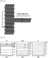
- FIG. 25 is a schematic diagram showing growth modes observed using a scanning transmission electron microscope
- FIG. 26 is a schematic diagram showing lateral and axial alignment observed using a scanning transmission electron microscope.
- the growth of the layered ferric rust according to an embodiment of the present disclosure proceeds mainly in the axial and lateral directions, and the size thereof is stabilized within 8 hours.
- FIG. 27 includes graphs showing in-situ thermal XRD patterns for powder including layered ferric rust according to an embodiment of the present disclosure under air (oxidizing), Ar+H 2 (reducing), and Ar (inert) atmospheres
- FIG. 28 is a graph showing a phase change diagram for FIG. 27 .
- the layered ferric rust according to an embodiment of the present disclosure is prepared by performing the second heat treatment step at a temperature of 300 °C or less.
- FIG. 29 shows transmission electron microscope images and electron diffraction patterns showing changes depending on second heat treatment time (reaction time) for layered ferric rust according to an embodiment of the present disclosure.
- the LFR is synthesized through an intermediate in a stepwise transformation.
- Thermodynamically stable iron oxide is generally synthesized through a metastable phase rather than directly synthesized from ions in a solution.
- ferrihydrite having low crystallinity is generated as an intermediate before LFR formation.
- 7 nm nanoplatelets in the form of particles having an interlayer spacing of 1.2 nm begin to form in the intermediate, and portions where adjacent nanoplatelets adhere at different angles are observed.
- Nanoplatelets are used as building blocks to grow the LFR. At this time, the LFR grows in both the thickness and stacking directions over time, and the size thereof is stabilized after about 8 hours.
- FIG. 30 includes transmission electron microscope (TEM) images of layered ferric rust according to an embodiment of the present disclosure depending on the contents of a solvent (H 2 O)
- FIG. 31 includes graphs showing the powder X-ray diffraction (XRPD) of layered ferric rust according to an embodiment of the present disclosure depending on the contents of a solvent (H 2 O)
- FIG. 32 is a graph showing the proportion of phase change from magnetite to layered ferric rust according to an embodiment of the present disclosure depending on the contents of a solvent (H 2 O).
- LFR is influenced by the conditions of the chemical components mentioned in the synthesis method.
- the role of excess water added in the crystallization process of magnetite and ferrihydrite is important.
- the iron ion precursor reacts with acetate and hydrogen ions supplied from water in ethylene glycol (EG) to generate Fe 3+ of ferrihydrite.
- EG ethylene glycol
- a dehydration process and reduction by ethylene glycol (EG) occur to generate ferric hydroxide (Fe 2 O 3 ⁇ H 2 O) and magnetite.
- the ratio of hydroxyl group/iron according to the amount of water is an important factor. As the amount of water increases, dehydration and reduction reactions required for conversion into magnetite are inhibited, and LFR production becomes more stable than magnetite.
- the iron hydroxide nanoparticles according to an embodiment of the present disclosure may be included in at least one of a pollutant adsorbent, a battery catalyst, an oxygen evolution reaction (OER) catalyst, a thermal therapy material, bioplastics, a construction material, a pigment, and a dye.
- a pollutant adsorbent e.g., a battery catalyst
- OER oxygen evolution reaction
- the arsenic adsorbent according to an embodiment of the present disclosure may reduce the bioavailability of arsenic through strong arsenic adsorption using the organic-inorganic composite iron hydroxide nanoparticles.
- FIG. 33 is a schematic diagram showing an arsenic adsorbent according to an embodiment of the present disclosure
- FIG. 34 is a schematic diagram showing the mechanism of arsenic adsorption in soil using an arsenic adsorbent according to an embodiment of the present disclosure.
- the arsenic adsorbent according to an embodiment of the present disclosure includes organic-inorganic composite iron hydroxide nanoparticles 210, and the organic-inorganic composite iron hydroxide nanoparticles 210 include two or more nanoplatelet layers (nanoplatelets; 211, 211-1, 211-2) including one or more FeOe octahedral structures and organic ligands 212-1 and 212-2 intercalated between the two or more nanoplatelet layers 211.
- the arsenic adsorbent since the organic ligands 212-1 and 212-2 are intercalated between the nanoplatelet layers 211, the arsenic adsorbent may have the relatively wide interlayer spacing 213 compared to the size of nanoparticles.
- the organic-inorganic composite iron hydroxide nanoparticles 210 included in the arsenic adsorbent according to an embodiment of the present disclosure has a layered ferric rust crystal structure different from the conventional layered structure of other FeOOH (green rust, lepidocrocite) materials, through new pathways and intermediates that form Fe 3 O 4 , arsenic may be adsorbed and removed by using the wide interlayer spacing 213.
- the nanoplatelets 211 and the organic ligands 212-1 and 212-2 may be connected by bidentate bridging. Accordingly, the nanoplatelets 211 may have a zigzag structure due to edge-sharing of the adjacent FeOe octahedral structures 211 and corner-sharing by the organic ligands 212-1 and 212-2.
- the a-axis direction is similar to other FeOOH having a conventional layered structure due to edge-sharing of Fe atoms in the FeOe octahedrons.
- the organic-inorganic composite iron hydroxide nanoparticles 210 have the wide interlayer spacing 213 due to distortion caused by the organic ligands 212-1 and 212-2.
- the organic-inorganic composite iron hydroxide nanoparticles 210 may have a crystal structure different from other FeOOH having a conventional layered structure.
- the interlayer spacing 213 of the two or more nanoplatelet layers 211 may be 1.14 nm to 1.19 nm.
- the number of the two or more nanoplatelet layers 211 is not particularly limited, but the number of the two or more nanoplatelet layers 211 may be preferably 2 to 16.
- the interlayer spacing 213 of the two or more nanoplatelet layers 211 and the number of the two or more nanoplatelet layers 211 are proportional to synthesis time, as the heating time of a synthesis solution increases, the number of layers increases. After 8 hours, the speed at which the size of particles increases gradually slows down, and may reach a critical point at about 8 hours (average number of layers is 16).
- the nanoplatelets 211 may have a disk shape.
- the nanoplatelets 211 may include iron(III) oxide-hydroxide (FeOOH).
- the organic ligands 212-1 and 212-2 may preferably include an acetate (CH 3 COO - )-based compound, without being limited thereto.
- the acetate-based compound may include at least one of sodium acetate, potassium acetate, and ammonium acetate.
- the organic ligands 212-1 and 212-2 are intercalated between the two or more nanoplatelet layers 211, and thus the arsenic adsorbent includes the organic-inorganic composite iron hydroxide nanoparticles 210 having a layered ferric rust crystal structure having the relatively wide interlayer spacing 213 compared to the size of the particles.
- arsenic adsorption efficiency may be significantly improved by a primary adsorption mechanism in which arsenic is adsorbed by chemisorption at the surfaces of the nanoplatelets 211 and a secondary adsorption mechanism in which arsenic is adsorbed by electrostatic intercalation by the interlayer spacing 213 between the nanoplatelets 211.
- first arsenic 221 may be chemisorbed by the first organic ligands 212-1 and the second organic ligands 212-2 formed on the surfaces of the first nanoplatelets 211-1 and the second nanoplatelets 211-2, and at the same time, second arsenic 222 may be adsorbed through electrostatic intercalation by the interlayer spacing 213 formed by the second organic ligands 212-2 between the first nanoplatelets 211-1 and the second nanoplatelets 211-2.
- the primary mechanism relates to chemisorption.
- H 2 AsO 4 -1 removes organic ligands 212-1 and 212-2 (e.g., acetate) bound to the Fe layer, and is chemically adsorbed at the site where the organic ligands are removed.
- the secondary mechanism relates to layer intercalation.
- the H 2 AsO 4 -1 complex is physically adsorbed in a wide interlayer spacing between the layers.
- the arsenic adsorbent in the secondary mechanism, in the arsenic adsorbent according to an embodiment of the present disclosure, since the nanoplatelets 211 are stacked in the b-axis direction in a state in which octahedrons are twisted by the organic ligands 212-1 and 212-2, the arsenic adsorbent has the wide interlayer spacing 213, and thus arsenic may be easily introduced into the wide interlayer spacing 213, thereby improving the efficiency of removing arsenic by electrostatic intercalation.
- the arsenic adsorbent may maintain the soil ecosystem from the perspective of a sustainable environment and includes the organic-inorganic composite iron hydroxide nanoparticles 210 with increased adsorption of arsenic 221 and 222. Since the arsenic adsorbent is synthesized based on the structural reconstitution of hydroxide existing in nature, the arsenic adsorbent may improve arsenic adsorption efficiency while maintaining the soil environment.
- the arsenic adsorbent according to an embodiment of the present disclosure may be used as a soil improver.
- the FeOe octahedral structures of the organic-inorganic composite iron hydroxide nanoparticles 210 are linked to each other by edge-sharing in the a-axis direction. In the c-axis direction, edge-sharing is broken at the organic ligands 212-1 and 212-2 and corner-sharing may be performed.
- the nanoplatelets 211 including the FeOe octahedral structures may be formed on the ac plane and stacked in the b-axis direction to have the large interlayer spacing 213.
- a pair of corner-sharing FeO 6 octahedral structures may form a zigzag layered arrangement with edge-sharing.
- the organic ligands 212-1 and 212-2 may form a pair of the FeOe octahedral structures by bidentate bridging, and at the same time, may participate as a component of the FeOe octahedral structures with carboxylate thereof.
- the zigzag arrangement of the pairs of the FeOe octahedral structures and the b-axis stacking induced by the organic ligands 212-1 and 212-2 may determine the crystal structure of iron hydroxide.
- the organic-inorganic composite iron hydroxide nanoparticles 210 may have a completely different atomic arrangement compared to other iron hydroxides having a layered structure.
- ⁇ -FeOOH and green rust may have boehmite arranged in a zigzag arrangement along the ac plane and brucite having a planar FeO 3 (OH) 3 arrangement along the ab plane.
- organic-inorganic composite iron hydroxide nanoparticles 210 FeOe octahedral structures are bonded in the a-axis direction through edge-sharing by organic ligands. In the c-axis direction, edge-sharing is broken and corner-sharing occurs at the organic ligands 212-1 and 212-2 to form a layered ferric rust crystal structure, and thus the organic-inorganic composite iron hydroxide nanoparticles 210 may have a completely different crystal structure.
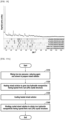
- FIG. 35 is a schematic diagram showing a method of preparing an arsenic adsorbent according to an embodiment of the present disclosure
- FIG. 36 is a schematic diagram showing a method of preparing an arsenic adsorbent according to an embodiment of the present disclosure in detail.
- the method of preparing the arsenic adsorbent according to an embodiment of the present disclosure includes the same components as the arsenic adsorbent according to an embodiment of the present disclosure, description of the same components will be omitted.
- step S210 of mixing an iron ion precursor, a reducing agent, an organic ligand precursor, and a solvent to prepare a mixed solution is performed.
- Iron chloride hexahydrate (FeCl 3 ⁇ 6H 2 O) is preferably used as the iron ion precursor, without being limited thereto.
- the reducing agent may simultaneously act as a solvent.
- Ethylene glycol (EG) is preferably used as the reducing agent, without being limited thereto.
- the reducing agent may include at least one of ethylene glycol, di-ethylene glycol, tri-ethylene glycol, and tetra-ethylene glycol.
- the solvent may be water (H 2 O).
- the organic ligand precursor preferably includes an acetate (CH 3 COO - )-based compound, without being limited thereto.
- the acetate-based compound may include at least one of sodium acetate, potassium acetate, and ammonium acetate.
- step S220 of heating the mixed solution to grow organic-inorganic composite iron hydroxide nanoparticles is performed.
- Step S220 of heating the mixed solution to grow organic-inorganic composite iron hydroxide nanoparticles may include first heat treatment step S221 of heating for 15 minutes to increase the temperature of the mixed solution to 200 °C and second heat treatment step S222 of maintaining the temperature of the mixed solution at 200 °C for 8 hours.
- the first heat treatment step S221 is a process of reaching the temperature of the second heat treatment step S222.
- the temperature of the mixed solution may be increased to 200 °C for 15 minutes.
- the second heat treatment step S222 is a process of forming iron hydroxide FeOOH from ferrihydrite.
- crystals may be grown by heating the mixed solution at 200 °C for 8 hours.
- the reaction is initiated by heat treatment, and metastable iron hydroxide phases such as green rust and ferrihydrite may be formed to form thermodynamically stable iron oxides such as hematite and magnetite by an iron ion precursor.
- the iron ion precursor may react with acetate (organic anions) supplied from ethylene glycol as the reducing agent and hydroxyl ions supplied from the solvent (water) to form ferrihydrite.
- the organic-inorganic composite iron hydroxide nanoparticles having a layered ferric rust crystal structure as an intermediate phase material may be prepared by adjusting the content of the solvent.
- iron hydroxide (FeOOH) is changed to magnetite through dehydration and reduction processes.
- hydroxyl groups OH -
- iron hydroxide FeOOH
- the dehydration and reduction processes that convert iron hydroxide (FeOOH) into magnetite are hindered, so that iron hydroxide remains as it is without being converted to magnetite.
- hydroxyl groups may be supplemented by adding a sufficient amount of water.
- the arsenic adsorbent according to an embodiment of the present disclosure may have a novel crystal structure different from the known ferric hydroxide layered structure of lepidocrocite and green rust.
- the ratio of hydroxyl group/iron may be controlled by the content of the solvent included in the mixed solution.
- the ratio of hydroxyl group/iron is an important factor in the process of converting iron hydroxide into magnetite.
- the ratio of hydroxyl group/iron (OH - /Fe) increases, hindering the dehydration and reduction reactions required to convert iron hydroxide (ferric oxyhydroxide) into magnetite.
- the content of the solvent may be 150 mmol to 400 mmol.
- the organic-inorganic composite iron hydroxide nanoparticles (For example; Layered ferric rust) are not generated.
- the amount of the organic-inorganic composite iron hydroxide nanoparticles produced may be controlled by the content of the solvent.
- the second heat treatment step S222 may include step S222-1 of forming ferrihydrite nanocrystals in the mixed solution, step S222-2 of forming nanoplatelets on the surface of the ferrihydrite nanocrystals, and step S222-3 of attaching two or more nanoplatelet layers at different angles to grow a layered ferric rust crystal structure.
- ferrihydrite crystals having low crystallinity which are intermediates before conversion into magnetite, may be generated (S222-1).
- the size of organic-inorganic composite iron hydroxide nanoparticles may be stabilized.
- the nanoplatelet attachment method may be largely divided into three types: axial, lateral, and axial + lateral.
- the synthesis may be controlled according to the second heat treatment time.
- step S210 of mixing an iron ion precursor, a reducing agent, an organic ligand precursor, and a solvent to prepare a mixed solution may further include a step of adjusting the pH of the mixed solution.
- goethite is formed through a typical crystallization method without a reducing agent and organic ligands. Even when goethite is formed, when the goethite is mixed with the reducing agent and the organic ligand precursor, pH was adjusted to 1.5 or less, and then first heat treatment and second heat treatment are performed, organic-inorganic composite iron hydroxide nanoparticles may be grown.
- the iron ion precursor preferably iron chloride hexahydrate (FeCl 3 ⁇ 6H 2 O
- organic-inorganic composite iron hydroxide nanoparticles may be grown from ferrihydrite synthesized at pH 7 through particle-attached growth through heat treatment using the reducing agent and the organic ligands in the range of pH 1 to 2.
- organic-inorganic composite iron hydroxide nanoparticles may be prepared when heat treatment is performed after adjusting the pH of the mixed solution.
- organic-inorganic composite iron hydroxide nanoparticles may be prepared by a particle-attached growth method when pH is adjusted to 2 or less. Even when goethite is formed through a typical crystallization method at pH 7, when the goethite is mixed with the reducing agent and the organic ligand precursor and pH is adjusted to 1.5 or less, organic-inorganic composite iron hydroxide nanoparticles may be prepared by a particle-attached growth method through heat treatment.
- the pH of the mixed solution may be 1 to 2.
- step S130 of cooling the heated mixed solution is performed.
- the process of generating the layered structure may be terminated.
- step S140 of washing the cooled mixed solution to obtain organic-inorganic composite iron hydroxide nanoparticles is performed.
- the method of preparing the arsenic adsorbent by synthesizing organic-inorganic composite iron hydroxide nanoparticles using iron hydroxide, which is a mineral abundant in the earth, by reconstituting ferrihydrite and hydroxide polymorph (goethite) that exist in nature, natural-friendly and economical nanomaterials capable of arsenic immobilization may be prepared.
- Oxyhydroxide (ferrihydrite): Oxyhydroxide was synthesized by adding 0.1 M Fe(NO 3 ) 3 to 330 mL of 1 M KOH until pH satisfies the range of 7 to 8.
- the control is a soil sample containing no goethite (Gt) and organic-inorganic composite iron hydroxide nanoparticles.
- Organic-inorganic composite iron hydroxide nanoparticles were prepared by chemically reacting FeCl 3 ⁇ 6H 2 O, ethylene glycol, and acetate as a surface ligand under an acidic condition (pH ⁇ 2) through Pathway 1 of FIG. 4 .
- FeCl 3 ⁇ 6H 2 O was reacted with acetate in a mixture of water and ethylene glycol at 200 °C for 8 hours.
- FIG. 37 includes images showing a process of preparing an arsenic adsorbent according to Example 2 of the present disclosure.
- the arsenic adsorbent according to Example 2 of the present disclosure is capable of large-scale synthesis (40 g of nanoparticles per batch).
- FIG. 38 includes scanning electron microscope (SEM) and transmission electron microscope (TEM) images showing the layer structure of an arsenic adsorbent according to Example 2 of the present disclosure.
- the organic-inorganic composite iron hydroxide nanoparticles included in the arsenic adsorbent according to Example 2 of the present disclosure may have a length of 22.4 ⁇ 2.59 nm, a thickness of 16.3 ⁇ 3.35 nm, and an interlayer spacing of 1.14 nm.
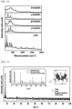
- FIG. 39 includes an image showing the selected-area electron diffraction (SAED) pattern of an arsenic adsorbent according to Example 2 of the present disclosure and a graph showing powder X-ray diffraction (XRPD) results.
- SAED selected-area electron diffraction
- XRPD powder X-ray diffraction
- the organic-inorganic composite iron hydroxide nanoparticles included in the arsenic adsorbent according to Example 2 of the present disclosure have a different structure from other hydroxide polymorphs in nature.
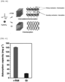
- FIG. 40 is a schematic diagram showing an arsenic (As) adsorption mechanism
- FIG. 41 is a graph showing inductively coupled plasma mass spectroscopy (ICP-MS) results showing the adsorption capacity of an arsenic adsorbent according to Comparative Example 1 and an arsenic adsorbent according to Example 2 of the present disclosure
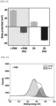
- FIG. 42 is a graph showing electrokinetic potential before and after arsenic adsorption.
- the potential of the arsenic adsorbent according to Comparative Example 1 decreased from 39.3 mV to -14.2 mV.
- the potential of the arsenic adsorbent according to Example 2 of the present disclosure decreased from 12.1 mV to - 32.1 mV.
- the arsenic adsorbent according to Comparative Example 1 adsorbs arsenic through a primary mechanism in which arsenic is chemically bonded only to the outer surface.
- the arsenic adsorbent according to Example 2 of the present disclosure adsorbs arsenic through a secondary mechanism in which arsenic is chemically bonded to the surface in a wide interlayer spacing and arsenic is physically inserted into an interlayer space.
- FIG. 43 is a graph showing the X-ray photoelectron spectroscopy (XPS) results of an arsenic adsorbent according to Comparative Example 1 before arsenic adsorption
- FIG. 44 is a graph showing the X-ray photoelectron spectroscopy results of an arsenic adsorbent according to Comparative Example 1 after arsenic adsorption
- FIG. 45 is a graph showing the X-ray photoelectron spectroscopy results of an arsenic adsorbent according to Example 2 of the present disclosure before arsenic adsorption
- FIG. XPS X-ray photoelectron spectroscopy
- FIG. 46 is a graph showing the X-ray photoelectron spectroscopy results of an arsenic adsorbent according to Example 2 of the present disclosure after arsenic adsorption
- FIG. 47 is a graph showing the Fourier-transform infrared spectroscopy (FT-IR) results of an arsenic adsorbent according to Example 2 of the present disclosure before and after arsenic adsorption
- FIG. 48 is a graph showing the Fourier-transform infrared spectroscopy results of an arsenic adsorbent according to Comparative Example 1 before and after arsenic adsorption.
- FT-IR Fourier-transform infrared spectroscopy
- arsenic is mainly intercalated between layers of organic-inorganic composite iron hydroxide nanoparticles included in the arsenic adsorbent according to Example 2 of the present disclosure in the form of AsO 4 .
- FIG. 49 is a graph showing the bioassay results of A. kimi in the absence of arsenic in artificial soil
- FIG. 50 is a graph showing the bioassay results of B. juncea in artificial soil that is not treated with arsenic.
- FIG. 51 is a graph showing the bioassay results of A. kimi in artificial soil treated with arsenic (Circles represent adults, and bars represent larvae)
- FIG. 52 is a graph showing arsenic contents in artificial soil treated with arsenic
- FIG. 53 includes images of A. kimi in artificial soil treated with arsenic
- FIG. 54 is a graph showing B. juncea in artificial soil
- FIG. 55 is a graph showing the contents of arsenic in B. juncea in artificial soil
- FIG. 56 includes images of B. juncea in artificial soil.
- the number (9.2 ⁇ 0.8) of live adult specimens according to treatment of the arsenic adsorbent according to Comparative Example 1 or the arsenic adsorbent according to Example 2 of the present disclosure was higher than the number (5.6 ⁇ 0.9) of live adult specimens according to treatment of the control sample according to Comparative Example 2.
- the concentration of arsenic in the body was 22.3 ⁇ 10.1 mg/kg, 37.2 ⁇ 21.2 mg/kg, and 5.1 ⁇ 2.9 mg/kg for treatment of the arsenic adsorbent according to Comparative Example 1, the control sample according to Comparative Example 2, and the arsenic adsorbent according to Example 2 of the present disclosure, respectively.
- the concentration of arsenic in the body of A. kimi was significantly low in the arsenic adsorbent according to Example 2 of the present disclosure.
- A. kimi adults produced noticeably more offspring than Comparative Example 1 and Comparative Example 2 (white dots).
- the average weights of roots and shoots varied in the range of 0.008 ⁇ 0.002 to 0.13 ⁇ 0.02 and 0.1 ⁇ 0.01 to 0.36 ⁇ 0.02, respectively.
- the weight was significantly increased when treated with the arsenic adsorbent according to Example 2 of the present disclosure.
- the accumulated arsenic concentrations of B. juncea were 5.29 ⁇ 1.10, 5.13 ⁇ 1.39, and 0.34 ⁇ 0.04 mg/kg for treatment of the arsenic adsorbent according to Comparative Example 1, the control sample according to Comparative Example 2, and the arsenic adsorbent according to Example 2 of the present disclosure, respectively.
- the accumulated arsenic concentration of B. juncea was significantly low and the specimens grew noticeably fast when treated with the arsenic adsorbent according to Example 2 of the present disclosure.
- the arsenic adsorbent according to Example 2 of the present disclosure reduces the arsenic bioavailability of A. kimi and B. juncea in the arsenic-contaminated soil, thereby increasing the fitness thereof.
- FIGS. 57 to 62 are graphs and images showing biological test results for treatment of an arsenic adsorbent (Gt) according to Comparative Example 1, an arsenic adsorbent (Control) according to Comparative Example 2, and an arsenic adsorbent (r-FAN) according to Example 2 of the present disclosure as modifiers for As-contaminated mine soil in Collembolan breeding ( A. kimi ) and phytotoxicity ( B. juncea ) tests.
- Gt arsenic adsorbent
- Control arsenic adsorbent
- r-FAN arsenic adsorbent
- FIG. 57 is a graph showing the number of surviving A. kimi adults (circles) and larvae (bars) after exposure to As-contaminated mine soil for 28 days.
- the number of surviving adults in soil treated with the arsenic adsorbent according to Comparative Example 1, the control sample according to Comparative Example 2, and the arsenic adsorbent according to Example 2 of the present disclosure was 8.0 ⁇ 0.0, 6.8 ⁇ 1.3, and 8.75 ⁇ 1.0, respectively.
- the number of offspring was 50.8 ⁇ 24.5, 56.5 ⁇ 8.9, and 97.0 ⁇ 21.1, respectively.
- FIG. 58 is a graph showing the average As concentration (mg/kg) of surviving adults after arsenic exposure.
- soil treated with the arsenic adsorbent according to Example 2 of the present disclosure had the highest number of surviving adults and the highest number of offspring.
- the arsenic body concentrations of A. kimi were 70.1 ⁇ 25.1, 62.5 ⁇ 9.5, and 41.0 ⁇ 14.5 mg/kg under treatment of the arsenic adsorbent according to Comparative Example 1, the control sample according to Comparative Example 2, and the arsenic adsorbent according to Example 2 of the present disclosure, respectively.
- FIG. 59 includes images of larval specimens produced after arsenic exposure.
- FIG. 60 is a graph showing the weight (g) of roots and shoots of B. juncea after arsenic exposure.
- the average root weights of groups treated with the arsenic adsorbent according to Comparative Example 1, the control sample according to Comparative Example 2, and the arsenic adsorbent according to Example 2 of the present disclosure were 0.08 ⁇ 0.01, 0.06 ⁇ 0.01, and 0.10 ⁇ 0.01g, respectively.
- the group treated with the arsenic adsorbent according to Example 2 of the present disclosure showed significantly higher root weight.
- the group treated with the arsenic adsorbent according to Comparative Example 1 exhibited an average sprout weight of 0.39 ⁇ 0.04, and the control group of Comparative Example 2 exhibited an average sprout weight of 0.49 ⁇ 0.03.
- the group treated with the arsenic adsorbent according to Comparative Example 1 exhibited the lowest average sprout weight.
- FIG. 61 is a graph showing the average As concentration (mg/kg) of B. juncea after arsenic exposure.
- the accumulated arsenic concentrations of B. juncea were 6.6 ⁇ 0.5, 8.7 ⁇ 1.1, and 6.3 ⁇ 0.3 mg/kg, respectively.
- FIG. 62 includes images showing B. juncea growth after arsenic exposure.
- the accumulated arsenic concentration of B. juncea was significantly low in the groups treated with the arsenic adsorbent according to Comparative Example 1 and the arsenic adsorbent according to Example 2 of the present disclosure compared to the group treated with the control sample of Comparative Example 2. Despite significant differences in root weight and accumulated arsenic concentration in B. juncea after arsenic exposure, there was no appreciable change in shoot appearance between the treatment groups.
- the arsenic adsorbent according to Example 2 of the present disclosure significantly reduces arsenic bioavailability in old mine soil having a high arsenic concentration.
- FIG. 63 includes images showing the morphological characteristics of an arsenic adsorbent according to Example 2 of the present disclosure in artificial soil (a) and arsenic-contaminated soil (b).
- the shape and phase of the arsenic adsorbent according to Example 2 of the present disclosure lasted for 28 days.
- treatment with the arsenic adsorbent according to Comparative Example 1 and the arsenic adsorbent according to Example 2 of the present disclosure did not change soil pH and EC significantly enough to affect soil microbes or plant.
- Table 4 shows the pH and EC of arsenic-contaminated mine soil and artificial soil 28 days after adding the arsenic adsorbent according to Comparative Example 1 and the arsenic adsorbent according to Example 2 of the present disclosure.
- pH EC Comparative Example 2 Comparative Example1 Example 2 Comparative Example 2 Comparative Example1
- Example 2 Artificial Soil Gilgok 7.5 ⁇ 0.02 7.2 ⁇ 0.02 7.3 ⁇ 0.04 119 ⁇ 1.5 105.0 ⁇ 2.0 67.7 ⁇ 2.3
- soil treated with the arsenic adsorbent according to Example 2 of the present disclosure exhibited the lowest pH and EC because the ionic strength of pore water was reduced by adsorption and intercalation of a significant amount of bioavailable arsenic in a soil improver.
- FIG. 64 includes graphs showing Olsen extraction results in arsenic-contaminated artificial soil (a) and arsenic-contaminated mine soil (b) according to treatment of an arsenic adsorbent (Gt) according to Comparative Example 1, an arsenic adsorbent (Control) according to Comparative Example 2, and an arsenic adsorbent (r-FAN) according to Example 2 of the present disclosure.
- Gt arsenic adsorbent
- r-FAN arsenic adsorbent
- Olsen extractable arsenic was measured after 28 days of exposure to observe the immobilization effect of the arsenic adsorbent according to Example 2 of the present disclosure on bioavailable arsenic.
- the arsenic adsorbent according to Example 2 of the present disclosure showed three times greater arsenic-immobilization than the arsenic adsorbent according to Comparative Example 1.
- the F3 ratio (low crystalline functional metal oxide) increased to a level similar to that of F2. This indicated two states of arsenic species bound to the arsenic adsorbent according to Example 2 of the present disclosure with different binding strengths.
- the arsenic adsorbent according to Example 2 of the present disclosure converted F1 to F3 species by incorporating arsenic into the crystal structure through an intercalation mechanism in addition to surface adsorption.
- the As fraction distribution in mine soil included a small proportion of bioavailable F1-F2 and a high proportion of crystallized As in the form of F3-F5.
- the arsenic adsorbent according to Example 2 of the present disclosure effectively reduced F1, which is the most toxic bioavailable form to plants and animals, by retaining arsenic in stationary forms corresponding to F2 and F3. Accordingly, the arsenic adsorbent according to Example 2 of the present disclosure showed a mechanism to restore ecological health in both soil types.
- FIG. 65 is a graph showing average percentage ratios for different forms of arsenic in artificial soil
- FIG. 66 is a graph showing average percentage ratios for different forms of arsenic in mine soil.
- F1 is a form of non-specifically bound arsenic
- F2 is a form of specifically chemically bound arsenic
- F3 is a form of amorphous arsenic hydroxide.
- Table 6 shows the results of FIGS. 65 and 66 [Table 6] Soil type Treatment F1 F2 F3 F4 F5 Sum of As fraction 1-5 As-spiked artificial soil Comparative Example 2 63.4 ⁇ 4.4a (29.9 ⁇ 3.5) 18.5 ⁇ 0.7c (8.7 ⁇ 0.8) 4.6 ⁇ 1.0b (2.2 ⁇ 0.6) 5.6 ⁇ 0.6b (2.6 ⁇ 0.2) 7.9 ⁇ 3.7a (3.7 ⁇ 1.5) 47.1 ⁇ 3.3 Comparative Example 1 37.4 ⁇ 3.7b (18.5 ⁇ 0.7) 27.5 ⁇ 0.5b (13.7 ⁇ 1.3) 9.6 ⁇ 1.4b (4.8 ⁇ 1.1) 16.6 ⁇ 1.0a (8.3 ⁇ 1.2) 9.0 ⁇ 1.2a (4.5 ⁇ 1.0) 49.8 ⁇ 4.6
- the adsorption amount of arsenic in the form of F3 is significantly high, indicating that the arsenic adsorbent according to Example 2 includes an arsenic adsorption mechanism by interlayer intercalation, which is different from the mechanism of the arsenic adsorbent according to Comparative Example 1 (Gt).
- layered ferric rust having a novel crystal structure in which organic anions are intercalated between nanoplatelet layers to have a relatively wide interlayer spacing compared to a nanoparticle size, and iron hydroxide nanoparticles including the layered ferric rust can be provided.
- layered ferric rust in which organic anions induce distortion in the arrangement of FeO 6 octahedrons included in nanoplatelets and form a stacked structure of the nanoplatelets, and iron hydroxide nanoparticles including the layered ferric rust can be provided.
- iron hydroxide nanoparticles having a layered ferric rust crystal structure that forms a stacked structure of nanoplatelets by a mechanism in which solvent molecules participate in a dehydration process during a chemical reaction of converting metastable ferrihydrite into stable magnetite by adjusting the amounts of organic anions and a solvent when preparing iron hydroxide nanoparticles, and a method of preparing the iron hydroxide nanoparticles can be provided.
- an arsenic adsorbent including natural-friendly and economical organic-inorganic composite iron hydroxide nanoparticles capable of immobilizing arsenic using iron hydroxide, which is a mineral abundant in the earth, and a method of preparing the arsenic adsorbent can be provided.
- an arsenic adsorbent capable of immobilizing arsenic through a primary adsorption mechanism that adsorbs arsenic by chemical adsorption through the surfaces of nanoplatelets and a secondary adsorption mechanism that intercalates/immobilizes arsenic by electrostatic intercalation through interlayer spacing formed by organic ligands intercalated between layers of nanoplatelets, and a method of preparing the arsenic adsorbent can be provided.
- an arsenic adsorbent capable of preparing organic-inorganic composite iron hydroxide nanoparticles including organic ligands intercalated between layers of nanoplatelets through colloidal assembly of nano-scale building blocks through a particle-directed attachment process, and a method of preparing the arsenic adsorbent can be provided.
- NANOPLATELETS 111 FEO 6 OCTAHEDRAL STRUCTURES 120: INTERLAYER SPACING 121: ORGANIC ANIONS 210: ORGANIC-INORGANIC COMPOSITE IRON HYDROXIDENANOPARTICLES 211: NANOPLATELETS 211-1: FIRST NANOPLATELETS 211-2: SECOND NANOPLATELETS 212-1: FIRST ORGANIC LIGANDS 212-2: SECOND ORGANIC LIGANDS 221: FIRST ARSENIC 222: SECOND ARSENIC
Landscapes
- Chemical & Material Sciences (AREA)
- Organic Chemistry (AREA)
- Chemical Kinetics & Catalysis (AREA)
- Analytical Chemistry (AREA)
- Inorganic Chemistry (AREA)
- Engineering & Computer Science (AREA)
- Materials Engineering (AREA)
- Nanotechnology (AREA)
- Life Sciences & Earth Sciences (AREA)
- Soil Sciences (AREA)
- Environmental & Geological Engineering (AREA)
- Crystallography & Structural Chemistry (AREA)
- Compounds Of Iron (AREA)
- Solid-Sorbent Or Filter-Aiding Compositions (AREA)
- Laminated Bodies (AREA)
Abstract
(a) a crystal system belongs to a monoclinic system;
(b) a space group belongs to Pn (No. 7); and
(c) unit cell parameters are a = 3.854 ± 0.002 Å, b = 11.491 ± 0.007 Å, c = 9.818 ± 0.004 Å, and β = 88.47 ± 0.005° (b is the distance between layers in the [010] axial direction).
Description
- This application claims priority to
Korean Patent Application No. 10-2022-0053803, filed on April 29, 2022 - The present disclosure relates to layered ferric rust and iron hydroxide nanoparticles including the same, and more particularly, to layered ferric rust having a new crystal structure due to anion organic matter intercalated between layered structures of iron oxide/ferric hydroxide and iron hydroxide nanoparticles including the layered ferric rust.
- Iron hydroxide is an abundant mineral that makes up 4 % of the Earth's crust, plays an important role in biogeochemical cycles and ecosystem maintenance, and is attracting attention in various fields such as metallurgy, water purification, energy conversion and storage. Naturally occurring iron hydroxide includes ferrihydrite, ferric hydroxide (FeOOH) polymorphs (goethite, akaganetie, lepidocorcite, and feroxyhyte), and green rust (
types 1 and 2). - In particular, to obtain a ceramic pigment with a vivid color, it is important to synthesize a nano pigment capable of controlling the shape and size of the pigment. When using iron hydroxide, various shapes from rod to spindle shapes may be implemented. At this time, depending on the shape, α-FeOOH (goethite), β-FeOOH (akaganeite), and γ-FeOOH (lepidocrocite) are used separately.
- Therefore, there is a demand for a preparation method capable of imparting diversity to surface area characteristics while enabling shape and size control through a simple process for iron hydroxide used for these various purposes.
- In addition, naturally occurring iron hydroxide is used as a precursor for formation of relatively thermodynamically stable iron oxide and plays an important role in the crystallization process of iron oxide. Accordingly, an iron hydroxide material with a new crystal structure may provide important information about the iron oxide crystallization process beyond basic understanding and technical impact thereof.
- Arsenic is an ingredient harmful to the human body and has been used as a material for poison in the past. Surprisingly, such arsenic is a substance that is commonly encountered in the surroundings. Arsenic is not only produced by production activities such as mining and smelting, but also occurs naturally.
- However, chronic exposure to arsenic may cause serious health problems, so inorganic arsenic is classified as a carcinogen. In addition, soil contaminated with arsenic (As) inevitably exists in nature, and removing arsenic is a global challenge for a sustainable environment.
- Accordingly, conventionally, attempts have been made to remove arsenic using nanomaterials having increased adsorption capacity and affinity. However, due to complex reasons including mass synthesis of nanomaterials, toxicity to the soil environment, and environmental problems, use of nanomaterials in soil is limited.
- Specifically, an adsorbent prepared by mixing iron oxide, iron oxyhydroxide, or a mixture thereof known as an arsenic-adsorbing material with a cation-selective binder resin is used to increase mechanical strength and arsenic adsorption efficiency.
- Despite these conventional techniques, purification techniques for arsenic contamination are still ineffective, and effective removal techniques for arsenic contamination are still required.
-
-
Korean Patent No. 1771005 -
Korean Patent Application Publication No. 2019-0085902 - Therefore, the present disclosure has been made in view of the above problems, and it is an object of the present disclosure to provide layered ferric rust having a novel crystal structure in which organic anions are intercalated between nanoplatelet layers to have a relatively wide interlayer spacing compared to a nanoparticle size, and iron hydroxide nanoparticles including the layered ferric rust.
- It is another object of the present disclosure to provide layered ferric rust in which organic anions induce distortion in the arrangement of FeO6 octahedrons included in nanoplatelets and form a stacked structure of the nanoplatelets, and iron hydroxide nanoparticles including the layered ferric rust.
- It is still another object of the present disclosure to provide iron hydroxide nanoparticles having a layered ferric rust crystal structure that forms a stacked structure of nanoplatelets by a mechanism in which solvent molecules participate in a dehydration process during a chemical reaction of converting metastable ferrihydrite into stable magnetite by adjusting the amounts of organic anions and a solvent when preparing iron hydroxide nanoparticles, and a method of preparing the iron hydroxide nanoparticles.
- It is still another object of the present disclosure to provide an arsenic adsorbent including natural-friendly and economical organic-inorganic composite iron hydroxide nanoparticles capable of immobilizing arsenic using iron hydroxide, which is a mineral abundant in the earth, and a method of preparing the arsenic adsorbent.
- It is still another object of the present disclosure to provide an arsenic adsorbent capable of immobilizing arsenic through a primary adsorption mechanism that adsorbs arsenic by chemical adsorption through the surfaces of nanoplatelets and a secondary adsorption mechanism that intercalates/immobilizes arsenic by electrostatic intercalation through interlayer spacings formed by organic ligands intercalated between layers of nanoplatelets, and a method of preparing the arsenic adsorbent.
- It is yet another object of the present disclosure to provide an arsenic adsorbent capable of preparing organic-inorganic composite iron hydroxide nanoparticles including organic ligands intercalated between layers of nanoplatelets through colloidal assembly of nano-scale building blocks through a particle-directed attachment process, and a method of preparing the arsenic adsorbent.
- In accordance with one aspect of the present disclosure, provided is layered ferric rust having a novel crystal structure that satisfies conditions (a) to (c) below:
- (a) a crystal system belongs to a monoclinic system; (b) a space group belongs to Pn (No. 7); and (c) unit cell parameters are a = 3.854 ± 0.002 Å, b = 11.491 ± 0.007 Å, c = 9.818 ± 0.004 Å, and β = 88.47 ± 0.005° (b is a distance between layers in a [010] axial direction).
- Atomic coordinates and equivalent isotropic displacement parameters in a lattice of the layered ferric rust may satisfy Table 1 below:
[Table 1] Element x y z Beq Occ. Fe(1) 0.4096(19) 0.4207(15) 0.293(7) 1 1 Fe(2) 0.409(2) 0.4391(16) 0.606(7) 1 1 C(1) 0.318(2) 0.669(5) 0.455(5) 2 1 C(2) 0.220(3) 0.789(5) 0.411(7) 2 1 O(1) 0.507(3) 0.239(8) 0.252(10) 2 1 O(2) 0.2716(16) 0.638(4) 0.577(5) 2 1 O(3) 0.899(5) 0.451(7) 0.298(17) 2 0.75 O(4) 0.426(4) 0.521(6) 0.104(17) 2 0.75 O(5) 0.424(3) 0.593(7) 0.371(5) 2 1 O(6) 0.258(2) 0.257(8) 0.637(10) 2 1 O(7) 0.563(3) 0.044(5) 0.322(5) 2 1 O(8) 0.584(2) 0.320(9) 0.454(14) 2 0.5 H(1) 0.343(4) 0.846(5) 0.461(8) 2 1 H(2) 0.267(4) 0.799(7) 0.317(7) 2 1 H(3) 0.56(3) 0.05(6) 0.227(8) 2 1 H(4) 0.63(3) -0.04(2) 0.32(6) 2 1 H(5) -0.026(3) 0.801(7) 0.428(8) 2 1 H(6) 0.42905 0.17156 0.64026 2 1 H(7) 0.50683 0.18654 0.19587 2 1 - The layered ferric rust may be represented by Chemical Formula 1 below:
[Chemical Formula 1] FeOxCyHz,
wherein x is a prime number between 3 and 3.5 (3≤x≤3.5), y is a prime number between 0.67 to 1 (0.67≤y≤1), and z is a prime number between 1.94 to 3.5 (1.94≤z≤3.5). - The layered ferric rust may include two or more nanoplatelet layers including one or more FeOe octahedral structures; and organic anions intercalated between the two or more nanoplatelet layers, wherein, in the two or more nanoplatelet layers, an interlayer spacing is created by the organic anions.
- The nanoplatelets and the organic anions may be bonded to each other by bidentate bridging.
- The nanoplatelets may include corner-sharing and edge-sharing of the adjacent FeOe octahedral structures in a zigzag pattern by the organic anions.
- The number of the two or more nanoplatelet layers may be 2 to 16.
- The nanoplatelets may include iron(III) oxide-hydroxide (FeOOH).
- The organic anions may include an acetate (CH3COO-)-based compound.
- In accordance with another aspect of the present disclosure, provided are iron hydroxide nanoparticles including the layered ferric rust according to an embodiment of the present disclosure.
- The iron hydroxide nanoparticles may be included in at least one of a pollutant adsorbent, a battery catalyst, an oxygen evolution reaction (OER) catalyst, a thermal therapy material, bioplastics, a construction material, a pigment, and a dye.
- In accordance with yet another aspect of the present disclosure, provided is an arsenic adsorbent including organic-inorganic composite iron hydroxide nanoparticles, wherein the organic-inorganic composite iron hydroxide nanoparticles include two or more nanoplatelet layers including one or more FeOe octahedral structures; and organic ligands intercalated between the two or more nanoplatelet layers, wherein the organic-inorganic composite iron hydroxide nanoparticles adsorb arsenic by chemisorption by surfaces of the nanoplatelets and by electrostatic intercalation by an interlayer spacing between the nanoplatelets.
- The interlayer spacing of the two or more nanoplatelet layers may be 1.14 nm to 1.19 nm.
- The nanoplatelets and the organic ligands may be bonded to each other by bidentate bridging.
- In the nanoplatelets, the adjacent FeOe octahedral structures may be corner-shared and edge-shared in a zigzag pattern by the organic ligands.
- The number of the two or more nanoplatelet layers may be 2 to 16.
- The nanoplatelets may include iron(III) oxide-hydroxide (FeOOH).
- The organic ligands may include an acetate (CH3COO-)-based compound.
- The arsenic may be included in soil.
- The above and other objects, features and other advantages of the present disclosure will be more clearly understood from the following detailed description taken in conjunction with the accompanying drawings, in which:
-
FIGS. 1A and 1B schematically show layered ferric rust (LFR) according to an embodiment of the present disclosure, which a novel crystal structure of iron hydroxide, and conventional crystal structures of iron hydroxide; -
FIG. 2 schematically shows layered ferric rust according to an embodiment of the present disclosure, andFIG. 3 schematically shows an example of nanoplatelets and organic anions included in layered ferric rust according to an embodiment of the present disclosure; -
FIG. 4 schematically shows a combined structure of nanoplatelets and organic anions included in layered ferric rust according to an embodiment of the present disclosure; -
FIG. 5 shows a bright-field transmission electron microscope image of layered ferric rust according to an embodiment of the present disclosure,FIG. 6 shows a scanning transmission electron microscope image of layered ferric rust according to an embodiment of the present disclosure taken at a low voltage of 80 kV, andFIG. 7 shows a selected-area electron diffraction analysis image of layered ferric rust according to an embodiment of the present disclosure; -
FIG. 8 is an intensity profile representing the interlayer spacing of layered ferric rust according to an embodiment of the present disclosure,FIG. 9 includes graphs showing the surface properties of layered ferric rust according to an embodiment of the present disclosure,FIGS. 10 to 14 are graphs showing the compositional analysis of layered ferric rust according to an embodiment of the present disclosure,FIG. 15 shows a Fourier transform infrared spectrum representing the coordination of acetate of layered ferric rust according to an embodiment of the present disclosure, andFIG. 16 shows Raman analysis spectra of layered ferric rust according to an embodiment of the present disclosure and ferric hydroxide polymorphs; -
FIG. 17 shows Rietveld analysis of synchrotron high-resolution powder neutron diffraction analysis that analyzes the crystal structure of layered ferric rust according to an embodiment of the present disclosure and an LFR crystal structure image thereof, andFIG. 18 is a graph showing the Rietveld analysis results of synchrotron high-resolution powder neutron diffraction analysis of layered ferric rust according to an embodiment of the present disclosure compared to a conventional crystal structure; -
FIG. 19A is a flowchart for explaining a method of preparing layered ferric rust according to an embodiment of the present disclosure, andFIG. 19B is a schematic diagram showing a process of forming an LFR crystal structure; -
FIG. 20 is a transmission electron microscope image of powder containing a high concentration of layered ferric rust according to an embodiment of the present disclosure on a glass substrate,FIG. 21 is a transmission electron microscope image of powder containing a medium concentration of layered ferric rust according to an embodiment of the present disclosure on a glass substrate,FIG. 22 is a transmission electron microscope image of powder containing a low concentration of layered ferric rust according to an embodiment of the present disclosure on a glass substrate, andFIG. 23 is a graph showing a Gaussian distribution of the width and the average length of thickness in a lamination direction of layered ferric rust according to an embodiment of the present disclosure measured using particles (n = 200) obtained through a transmission electron microscope; -
FIG. 24 is a graph showing the growth kinetics of layered ferric rust according to an embodiment of the present disclosure in lateral and axial directions,FIG. 25 is a schematic diagram showing growth modes observed using a scanning transmission electron microscope, andFIG. 26 is a schematic diagram showing lateral and axial alignment observed using a scanning transmission electron microscope; -
FIG. 27 includes graphs showing in-situ thermal XRD patterns for powder including layered ferric rust according to an embodiment of the present disclosure under air (oxidizing), Ar+H2 (reducing), and Ar (inert) atmospheres, andFIG. 28 is a graph showing a phase change diagram forFIG. 27 ; -
FIG. 29 shows transmission electron microscope images and electron diffraction patterns showing changes depending on second heat treatment time (reaction time) for layered ferric rust according to an embodiment of the present disclosure; -
FIG. 30 includes transmission electron microscope (TEM) images of layered ferric rust according to an embodiment of the present disclosure depending on the contents of a solvent (H2O),FIG. 31 includes graphs showing the powder X-ray diffraction (XRPD) of layered ferric rust according to an embodiment of the present disclosure depending on the contents of a solvent (H2O), andFIG. 32 is a graph showing the proportion of phase change from magnetite to layered ferric rust according to an embodiment of the present disclosure depending on the contents of a solvent (H2O); -
FIG. 33 is a schematic diagram showing an arsenic adsorbent according to an embodiment of the present disclosure, andFIG. 34 is a schematic diagram showing the mechanism of arsenic adsorption in soil using an arsenic adsorbent according to an embodiment of the present disclosure; -
FIG. 35 is a schematic diagram showing a method of preparing an arsenic adsorbent according to an embodiment of the present disclosure, andFIG. 36 is a schematic diagram showing a method of preparing an arsenic adsorbent according to an embodiment of the present disclosure in detail; -
FIG. 37 includes images showing a process of preparing an arsenic adsorbent according to Example 1 of the present disclosure; -
FIG. 38 includes scanning electron microscope (SEM) and transmission electron microscope (TEM) images showing the layer structure of an arsenic adsorbent according to Example 2 of the present disclosure; -
FIG. 39 includes an image showing the selected-area electron diffraction (SAED) pattern of an arsenic adsorbent according to Example 2 of the present disclosure and a graph showing powder X-ray diffraction (XRPD) results; -
FIG. 40 is a schematic diagram showing an arsenic (As) adsorption mechanism,FIG. 41 is a graph showing inductively coupled plasma mass spectroscopy (ICP-MS) results showing the adsorption capacity of an arsenic adsorbent according to Comparative Example 1 and an arsenic adsorbent according to Example 2 of the present disclosure, andFIG. 42 is a graph showing electrokinetic potential before and after arsenic adsorption; -
FIG. 43 is a graph showing the X-ray photoelectron spectroscopy (XPS) results of an arsenic adsorbent according to Comparative Example 1 before arsenic adsorption,FIG. 44 is a graph showing the X-ray photoelectron spectroscopy results of an arsenic adsorbent according to Comparative Example 1 after arsenic adsorption,FIG. 45 is a graph showing the X-ray photoelectron spectroscopy results of an arsenic adsorbent according to Example 2 of the present disclosure before arsenic adsorption,FIG. 46 is a graph showing the X-ray photoelectron spectroscopy results of an arsenic adsorbent according to Example 2 of the present disclosure after arsenic adsorption,FIG. 47 is a graph showing the Fourier-transform infrared spectroscopy (FT-IR) results of an arsenic adsorbent according to Example 2 of the present disclosure before and after arsenic adsorption, andFIG. 48 is a graph showing the Fourier-transform infrared spectroscopy results of an arsenic adsorbent according to Comparative Example 1 before and after arsenic adsorption; -
FIG. 49 is a graph showing the bioassay results of A. kimi in the absence of arsenic in artificial soil, andFIG. 50 is a graph showing the bioassay results of B. juncea in artificial soil that is not treated with arsenic; -
FIG. 51 is a graph showing the bioassay results of A. kimi in artificial soil treated with arsenic (Circles represent adults, and bars represent larvae),FIG. 52 is a graph showing arsenic contents in artificial soil treated with arsenic,FIG. 53 includes images of A. kimi in artificial soil treated with arsenic,FIG. 54 is a graph showing B. juncea in artificial soil,FIG. 55 is a graph showing the contents of arsenic in B. juncea in artificial soil, andFIG. 56 includes images of B. juncea in artificial soil; -
FIGS. 57 to 62 are graphs and images showing biological test results for treatment of an arsenic adsorbent (Gt) according to Comparative Example 1, an arsenic adsorbent (Control) according to Comparative Example 2, and an arsenic adsorbent (r-FAN) according to Example 2 of the present disclosure as modifiers for As-contaminated mine soil in Collembolan breeding (A. kimi) and phytotoxicity (B. juncea) tests; -
FIG. 63 includes images showing the morphological characteristics of an arsenic adsorbent according to Example 2 of the present disclosure in artificial soil (a) and arsenic-contaminated soil (b); -
FIG. 64 includes graphs showing Olsen extraction results in arsenic-contaminated artificial soil (a) and arsenic-contaminated mine soil (b) according to treatment of an arsenic adsorbent (Gt) according to Comparative Example 1, an arsenic adsorbent (Control) according to Comparative Example 2, and an arsenic adsorbent (r-FAN) according to Example 2 of the present disclosure; and -
FIG. 65 is a graph showing average percentage ratios for different forms of arsenic in artificial soil, andFIG. 66 is a graph showing average percentage ratios for different forms of arsenic in mine soil. - The present disclosure will now be described more fully with reference to the accompanying drawings and contents disclosed in the drawings. However, the present disclosure should not be construed as limited to the exemplary embodiments described herein.
- The terms used in the present specification are used to explain a specific exemplary embodiment and not to limit the present inventive concept. Thus, the expression of singularity in the present specification includes the expression of plurality unless clearly specified otherwise in context. It will be further understood that the terms "comprise" and/or "comprising", when used in this specification, specify the presence of stated components, steps, operations, and/or elements, but do not preclude the presence or addition of one or more other components, steps, operations, and/or elements thereof.
- It should not be understood that arbitrary aspects or designs disclosed in "embodiments", "examples", "aspects", etc. used in the specification are more satisfactory or advantageous than other aspects or designs.
- In addition, the expression "or" means "inclusive or" rather than "exclusive or". That is, unless mentioned otherwise or clearly inferred from context, the expression "x uses a or b" means any one of natural inclusive permutations.
- In addition, as used in the description of the disclosure and the appended claims, the singular form "a" or "an" is intended to include the plural forms as well, unless context clearly indicates otherwise.
- Although terms used in the specification are selected from terms generally used in related technical fields, other terms may be used according to technical development and/or due to change, practices, priorities of technicians, etc. Therefore, it should not be understood that terms used below limit the technical spirit of the present disclosure, and it should be understood that the terms are exemplified to describe embodiments of the present disclosure.
- Also, some of the terms used herein may be arbitrarily chosen by the present applicant. In this case, these terms are defined in detail below. Accordingly, the specific terms used herein should be understood based on the unique meanings thereof and the whole context of the present disclosure.
- Unless defined otherwise, all terms (including technical and scientific terms) used herein have the same meaning as commonly understood by one of ordinary skill in the art. It will be further understood that terms, such as those defined in commonly used dictionaries, should be interpreted as having a meaning that is consistent with their meaning in the context of the relevant art and the present disclosure, and will not be interpreted in an idealized or overly formal sense unless expressly so defined herein.
- In addition, in the following description of the present disclosure, a detailed description of known functions and configurations incorporated herein will be omitted when it may make the subject matter of the present disclosure unclear. The terms used in the specification are defined in consideration of functions used in the present disclosure, and can be changed according to the intent or conventionally used methods of clients, operators, and users. Accordingly, definitions of the terms should be understood on the basis of the entire description of the present specification.
- According to a method of preparing hydroxide, hydroxide is mainly formed through a particle-directed attachment process and grown through colloidal assembly of nano-scale building blocks. The particle-directed attachment process is known as a new growth model that is related to anisotropy or formation of a complex structure with an organic material.
-
FIGS. 1A and 1B schematically show layered ferric rust (LFR) according to an embodiment of the present disclosure, which a novel crystal structure of iron hydroxide, and conventional crystal structures of iron hydroxide. - Layered ferric rust according to an embodiment of the present disclosure is a novel crystal structure material having a relatively wide interlayer spacing compared to the size of particles due to acetate intercalated between layers of ferric hydroxide, and acetate, which is an organic anion, may form a layered ferric rust (LFR) structure by distorting the arrangement of FeO6 octahedrons and creating a lamination of hydroxide layers.
- In addition, water molecules added in excess in the process of synthesizing hydroxide may play a decisive role in formation of acetate and a novel crystal structure by participating in a dehydration process during a chemical reaction of converting metastable ferrihydrite into stable magnetite.
- The layered ferric rust according to an embodiment of the present disclosure has a novel crystal structure different from lepidocrocite and green rust having the known ferric hydroxide layered structure.
- The layered ferric rust according to an embodiment of the present disclosure has a novel crystal structure that satisfies the following conditions (a) to (c).
- (a) A crystal system belongs to a monoclinic system, (b) a space group belongs to Pn (No. 7), and (c) unit cell parameters are a = 3.854 ± 0.002 Å, b = 11.491 ± 0.007 Å, c = 9.818 ± 0.004 Å, and β = 88.47 ± 0.005° (b is the distance between layers in the [010] axial direction).
- "a" means one side of a unit cell in the [100] axial direction, "c" means one side of a unit cell in the [001] axial direction, and "β" means an angle between the ac plane and the b axis.
- When a material has one or more crystal structures, it is called polymorphism. The crystal structure is the internal structure of six crystal systems, and the properties of a material vary depending on the crystal structure thereof. The layered ferric rust according to an embodiment of the present disclosure has a novel crystal structure different from the crystal structures of existing FeOOH polymorphs through synchrotron HRPD and Raman analysis. The layered ferric rust according to an embodiment of the present disclosure preferably has a novel crystal structure that satisfying the following conditions: a crystal system belongs to a monoclinic system, a space group belongs to Pn (No. 7), and unit cell parameters are a = 3.854(2) Å, b = 11.491(7) Å, c = 9.818(4) Å, and β = 88.47(5)°(b is a distance between layers in the [010] axial direction).
- More specifically, the crystallographic data of the layered ferric rust according to an embodiment of the present disclosure is shown in Table 2 below.
[Table 2] Fe2O4H2·(CH3COO)·H2O Crystal system, space group Monoclinic system, Pn (No.7) a, Å 3.854(2) b, Å 11.491(7) c, Å 9.818(4) β 88.47(5)° Volume, Å3 434.6(4) Z 2 Formula weight (Mr ) 254.78 Density, calc. g/cm3 0.973 Temperature, K 298 Wavelength, Å 1.5225 Step scan increment, 2θ 0.02° 2θ range, ° 5 - 146.5 Rp 14.11 Rwp 19.65 Rexp 5.03 Rbragg 7.43 G.O.F 3.91 - In Table 2, the volume means the volume of a unit cell, Z means proton number, the formula weight means a sum of the atomic weights of elements included in a chemical formula, the density means a value obtained through weight/volume - TGA measurement, the temperature means a measurement temperature in synchrotron high-resolution powder neutron diffraction analysis, and the wavelength means the wavelength of X-ray used in synchrotron high-resolution powder neutron diffraction analysis.
- XRD is measured by scanning a diffraction angle (2θ) while an X-ray source and a detector move along the circumference. At this time, the 2θ range means a range to be scanned, step scan increment means increment of an incident angle, and an R-factor is a reliable factor for refinement results and expresses the difference between a calculated value and a measured value in %, indicating the reliability of the calculated value.
- Rp may be calculated by
Equation 1 below, Rwp may be calculated byEquation 2 below, Rexp may be calculated byEquation 3 below, and Rbragg may be calculated byEquation 4 below.


- When measuring the electron density of a sample with XRD, the electron density is actually distorted in a three-dimensional direction rather than a sphere due to the bonding or arrangement of atoms. In powder XRD, the electron density is assumed to be spherical and the extent to which the electron density diverges from the original is calculated. At this time, B is a thermal factor, and eq is a variable assuming a spherical shape.
- G.O.F. is good of fitness and a reduced chi-square test, and means a goodness-of-fit test that determines whether an observed ratio value is the same as an expected value.
- Table 2 shows the crystallographic data of LFR obtained from synchrotron high-resolution powder neutron diffraction analysis, including crystal systems, space groups, the length of each side of a unit cell, angle, volume, molecular weight, density, and information used for analysis, and the crystallographic data shows the reliability of the above analysis.
- Atomic coordinates and equivalent isotropic displacement parameters in the lattice of the layered ferric rust according to an embodiment of the present disclosure may satisfy Table 1 below.
[Table 1] Element x y z Beq Occ. Fe(1) 0.4096(19) 0.4207(15) 0.293(7) 1 1 Fe(2) 0.409(2) 0.4391(16) 0.606(7) 1 1 C(1) 0.318(2) 0.669(5) 0.455(5) 2 1 C(2) 0.220(3) 0.789(5) 0.411(7) 2 1 O(1) 0.507(3) 0.239(8) 0.252(10) 2 1 O(2) 0.2716(16) 0.638(4) 0.577(5) 2 1 O(3) 0.899(5) 0.451(7) 0.298(17) 2 0.75 O(4) 0.426(4) 0.521(6) 0.104(17) 2 0.75 O(5) 0.424(3) 0.593(7) 0.371(5) 2 1 O(6) 0.258(2) 0.257(8) 0.637(10) 2 1 O(7) 0.563(3) 0.044(5) 0.322(5) 2 1 O(8) 0.584(2) 0.320(9) 0.454(14) 2 0.5 H(1) 0.343(4) 0.846(5) 0.461(8) 2 1 H(2) 0.267(4) 0.799(7) 0.317(7) 2 1 H(3) 0.56(3) 0.05(6) 0.227(8) 2 1 H(4) 0.63(3) -0.04(2) 0.32(6) 2 1 H(5) -0.026(3) 0.801(7) 0.428(8) 2 1 H(6) 0.42905 0.17156 0.64026 2 1 H(7) 0.50683 0.18654 0.19587 2 1 - In Table 1, x, y, and z represent the coordinates of each atom in a unit cell, and Occ. is site occupancy, and means site occupancy (e.g., when one exists, it means 1) in which the corresponding atom exists at an atomic site in a unit cell. In addition, in Table 1, the number in parentheses is the standard deviation of a result value, and 0.4096(19) may mean 0.4096 ± 0.019.
- In addition, when measuring electron density with XRD, a thermal factor is calculated for each 3-dimensional direction. Atoms, due to bonding or arrangement thereof, have a contorted shape rather than a sphere. At this time, Beq is a value obtained by calculating a thermal factor assuming that the shape is spherical (eq).
- In addition, Occ. is occupancy (site occupancy), and is a value indicating a degree to which atoms occupy a unit cell when one oxygen atom is assumed to be 1.
- Table 1 shows the coordinates of all atoms in a unit cell in 3D space.
- The layered ferric rust according to an embodiment of the present disclosure may be represented by
Chemical Formula 1 below.
[Chemical Formula 1] FeOxCyHz
- In
Chemical Formula 1, x is a prime number between 3 and 3.5 (3≤x≤3.5), y is a prime number between 0.67 to 1 (0.67≤y≤1), and z is a prime number between 1.94 to 3.5 (1.94≤z≤3.5). - For example, the layered ferric rust according to an embodiment of the present disclosure may be FeO3.5CH3.5 or Fe2O4H2·(CH3COO)·H2O.
- The layered ferric rust according to an embodiment of the present disclosure may be synthesized by a particle-directed deposition process and may have a novel crystal structure due to organic anions intercalated between two or more nanoplatelet layers (e.g., ferric hydroxide).
- In particular, since organic anion molecules grafted onto building blocks (two or more nanoplatelet layers) are closely related to intermolecular interaction in an assembly process, by controlling organic anions (e.g., acetate), which are organic molecules, the crystal structure of hydroxide (e.g., ferric hydroxide) may be controlled in a wide range from the atomic level to the micro level.
- For example, γ-FeOOH and green rust (GR-2) may have boehmite arranged in a zigzag arrangement along the ac plane and brucite having a planar FeO3(OH)3 arrangement along the ab plane.
- However, in the layered ferric rust according to an embodiment of the present disclosure, an FeO6 octahedral structure is connected by edge-sharing in the a-axis direction by organic anions, and in the c-axis direction, edge-sharing is broken and corner-sharing is formed in the
organic anions 121. Thus, the layered ferric rust has a completely different crystal structure. - Hereinafter, the layered ferric rust according to an embodiment of the present disclosure will be described in detail with reference to
FIG. 2 . -
FIG. 2 schematically shows layered ferric rust according to an embodiment of the present disclosure, andFIG. 3 schematically shows an example of nanoplatelets and organic anions included in layered ferric rust according to an embodiment of the present disclosure. - The layered ferric rust according to an embodiment of the present disclosure includes two or more nanoplatelet layers 110 including one or more FeOe
octahedral structures 111 and theorganic anions 121 intercalated between the two or more nanoplatelet layers 110. Due to theorganic anions 121, the two or more nanoplatelet layers 110 have aninterlayer spacing 120, which is a distance between the layers. - That is, in the layered ferric rust according to an embodiment of the present disclosure, since the
organic anions 121 are intercalated between the nanoplatelet layers 110, the layered ferric rust may have the relativelywide interlayer spacing 120 compared to the size of nanoparticles. - Since the layered ferric rust has a crystal structure different from other FeOOH (green rust, lepidocrocite) materials having a conventional layered structure, by discovering new pathways and intermediates that form Fe3O4, contaminants may be adsorbed and removed by using the
wide interlayer spacing 120, and the layered ferric rust may be used as a battery catalyst. - The
nanoplatelets 110 and theorganic anions 121 may be connected by bidentate bridging. Accordingly, thenanoplatelets 110 may have a zigzag structure due to edge-sharing of the adjacent FeOeoctahedral structures 111 and corner-sharing by theorganic anions 121. - For example, the a-axis direction is similar to other FeOOH having a conventional layered structure due to edge-sharing of Fe atoms in the FeOe octahedrons. In the c-axis direction, the LFR has a wide interlayer spacing due to distortion caused by the
organic anions 121. In addition, since edge-sharing is broken and Fe atoms are attached by corner-sharing, the LFR may have a crystal structure different from other FeOOH having a conventional layered structure. The combined structure will be described in more detail inFIG. 3 . - The
interlayer spacing 120 of the two or more nanoplatelet layers 110 may be 1.14 nm to 1.19 nm. - The number of the two or more nanoplatelet layers 110 is not particularly limited, but the number of the two or more nanoplatelet layers 110 may be preferably 2 to 16.
- In addition, since the
interlayer spacing 120 of the two or more nanoplatelet layers 110 and the number of the two or more nanoplatelet layers 110 are proportional to the synthesis time of LFR, as the heating time of a synthesis solution increases, the number of layers increases. After 8 hours, the speed at which the size of particles increases gradually slows down, and may reach a critical point at about 8 hours (average number of layers is 16). - The
nanoplatelets 110 may have a disk shape. - The
nanoplatelets 110 may include iron(III) oxide-hydroxide (FeOOH). - The
organic anions 121 may preferably include an acetate (CH3COO-)-based compound, without being limited thereto. - For example, the acetate-based compound may include at least one of sodium acetate, potassium acetate, and ammonium acetate.
- According to an embodiment, the layered ferric rust according to an embodiment of the present disclosure may be included in iron hydroxide nanoparticles according to an embodiment of the present disclosure.
- The iron hydroxide nanoparticles according to an embodiment of the present disclosure may be included in at least one of a pollutant adsorbent, a battery catalyst, an oxygen evolution reaction (OER) catalyst, a thermal therapy material, bioplastics, a construction material, a pigment, and a dye.
- For example, when used as a pollutant adsorbent, in the iron hydroxide nanoparticles according to an embodiment of the present disclosure, since the
nanoplatelets 110 are stacked in the b-axis direction in a state in which the octahedrons are twisted by theorganic anions 121, thewide interlayer spacing 120 is formed, and thus contaminants are more easily introduced into thewide interlayer spacing 120, thereby improving the removal efficiency of the contaminants. - In addition, when used as a battery catalyst, in the iron hydroxide nanoparticles according to an embodiment of the present disclosure, since the
nanoplatelets 110 are stacked in the b-axis direction in a state in which the octahedrons are twisted by theorganic anions 121, thewide interlayer spacing 120 is formed, and thus large amounts of ions may be stored and transported in Na and Li batteries. - In addition, when used as an oxygen evolution reaction (OER) catalyst, in the iron hydroxide nanoparticles according to an embodiment of the present disclosure, since the
nanoplatelets 110 are stacked in the b-axis direction in a state in which the octahedrons are twisted by theorganic anions 121, the current density value thereof is higher than that of other FeOOH, thereby improving efficiency. -
FIG. 4 schematically shows a combined structure of nanoplatelets and organic anions included in layered ferric rust according to an embodiment of the present disclosure. - Referring to
FIG. 4 , the FeOeoctahedral structures 111 of the layered ferric rust according to an embodiment of the present disclosure are linked to each other by edge-sharing in the a-axis direction. In the c-axis direction, edge-sharing is broken at theorganic anions 121 and corner-sharing is done. - In this way, the nanoplatelets including the FeOe
octahedral structures 111 may be formed on the ac plane and stacked in the b-axis direction to have thelarge interlayer spacing 120. - When viewed in the [100] area direction, a pair of corner-sharing FeO6
octahedral structures 111 may form a zigzag layered arrangement with edge-sharing. - The
organic anions 121 may form a pair of the FeOeoctahedral structures 111 by bidentate bridging, and at the same time, may participate as a component of the FeOeoctahedral structures 111 with carboxylate thereof. - The zigzag arrangement of the pairs of the FeOe
octahedral structures 111 and the b-axis stacking induced by theorganic anions 121 may determine the crystal structure of iron hydroxide. - Accordingly, the layered ferric rust according to an embodiment of the present disclosure may have a completely different atomic arrangement compared to other iron hydroxides having a layered structure.
- LFR was obtained using a polyol method. Iron chloride hexahydrate (FeCl3·6H2O) was used as an iron ion precursor, ethylene glycol (EG) was used as a reducing agent and a solvent, and sodium acetate (CH3COONa) and H2O were used as adjuvants to impart a hydroxyl group (OH-).
- Using an ultrasonic generator, 3 mmol FeCl3·6H2O was dissolved in 400 mmol of H2O and 15 mmol CH3HOONa was dissolved in 50 mL of EG, and the prepared solutions were placed in a three-neck flask, followed by mechanical stirring for 15 minutes until yellowish brown turned reddish brown. Then, after rapidly heating to 200 °C for 15 minutes, reaction was allowed for 8 hours while maintaining the temperature. After cooling the reaction solution, washing was performed three or more times using ethanol.
-
FIG. 5 shows a bright-field transmission electron microscope image of layered ferric rust according to an embodiment of the present disclosure,FIG. 6 shows a scanning transmission electron microscope image of layered ferric rust according to an embodiment of the present disclosure taken at a low voltage of 80 kV, andFIG. 7 shows a selected-area electron diffraction analysis image of layered ferric rust according to an embodiment of the present disclosure. - Referring to
FIGS. 5 to 7 , it can be confirmed that the layered ferric rust according to an embodiment of the present disclosure exhibits a ring pattern at d = 1.14 nm. - At this time, the appearance of a strong pattern at d = 1.134 nm through electron diffraction analysis means that the stack of disc-shaped 2D layers has crystallographic regularity, and the wide interlayer spacing between layers is formed through acetate. In Fourier transform infrared analysis, strong vibration of acetate molecules was observed. It was confirmed that acetate and iron were combined by bidentate bridging. Then, the coordination numbers of acetate and iron were confirmed.
-
FIG. 8 is an intensity profile representing the interlayer spacing of layered ferric rust according to an embodiment of the present disclosure,FIG. 9 includes graphs showing the surface properties of layered ferric rust according to an embodiment of the present disclosure,FIGS. 10 to 14 are graphs showing the compositional analysis of layered ferric rust according to an embodiment of the present disclosure,FIG. 15 shows a Fourier transform infrared spectrum representing the coordination of acetate of layered ferric rust according to an embodiment of the present disclosure, andFIG. 16 shows Raman analysis spectra of layered ferric rust according to an embodiment of the present disclosure and ferric hydroxide polymorphs. - Table 3 shows the peak parameters of the Fourier transform infrared spectrum.
[Table 3] Wavelength (cm-1) Peaks (Peak assignment) 3425 -OH stretching v(-OH) 2939, 2920, 2868 sp3 (-CH3) C-H Stretching ν(-CH3) 1580 COO- Asymmetry vas COO- (Fe) 1446 COO- symmetry vs COO- (Fe) 1334 CH3 deformation δ(-CH3) bending 1222 C-H wagging 1127, 1091, 1065, 1025 ρ(CH3) O-C-C stretching, C-O-C stretching, C-CH3, C-O stretching 903, 888 v(C-C) C-C stretching, C-H bending - Referring to Table 3 and
FIGS. 8 to 16 , the spectrum for each element (Fe, C, O) was analyzed through X-ray photoelectron spectroscopy analysis. Based on these results, it was confirmed that the LFR is a type of ferric hydroxide. - Based on the results of comparing the Raman peaks of known ferric hydroxide polymorphs and the Raman peaks of the LFR through Raman analysis, it can be confirmed that the LFR has a different crystal structure. Next, the crystal structure of the LFR was analyzed by performing high-resolution powder neutron diffraction using a synchrotron. Based on the analysis results, it can be seen that the crystal structure of the LFR is different from that of green rust and lepidocrocite, which have a layered structure among existing ferric hydroxides.
-
FIG. 17 shows Rietveld analysis of synchrotron high-resolution powder neutron diffraction analysis that analyzes the crystal structure of layered ferric rust according to an embodiment of the present disclosure and an LFR crystal structure image thereof, andFIG. 18 is a graph showing the Rietveld analysis results of synchrotron high-resolution powder neutron diffraction analysis of layered ferric rust according to an embodiment of the present disclosure compared to a conventional crystal structure. - Referring to
FIGS. 17 and18 , the composition of the LFR was analyzed by in-situ X-ray diffraction, thermogravimetric analysis/differential thermal analysis, and Rutherford back scattering spectroscopy/elastic recoil detection analysis. - In the composition analysis, the composition of each element is FeOOH·0.5CH3COO, indicating that the LFR is a polymorph of ferric hydroxide.
- In addition, since the layered ferric rust according to an embodiment of the present disclosure does not match the graph line of the conventional crystal structure, it can be seen that the layered ferric rust has a completely different crystal structure.
- Based on the HRPD data, the crystal structure of the LFR was analyzed by an ab-initio method, and the results are shown in Tables 1 and 2 below. The crystal structure of the layered ferric rust according to an embodiment of the present disclosure satisfies the following conditions: (a) a crystal system belongs to a monoclinic system, (b) a space group belongs to Pn (No. 7), and (c) unit cell parameters are a = 3.854(2) Å, b = 11.491(7) Å, c = 9.818(4) Å, and β = 88.47(5)° (here, b is the distance between layers in the [010] axial direction).
-
FIG. 19A is a flowchart for explaining a method of preparing layered ferric rust according to an embodiment of the present disclosure, andFIG. 19B is a schematic diagram showing a process of forming an LFR crystal structure. - According to an embodiment, the layered ferric rust according to an embodiment of the present disclosure may be prepared by the following method.
- Since the method of preparing the layered ferric rust according to an embodiment of the present disclosure includes the same components as the layered ferric rust according to an embodiment of the present disclosure, description of the same components will be omitted.
- First, in the method of preparing the layered ferric rust according to an embodiment of the present disclosure,
step S 110 of mixing an iron ion precursor, a reducing agent, and a solvent to prepare a mixed solution is performed. - Iron chloride hexahydrate (FeCl3·6H2O) is preferably used as the iron ion precursor, without being limited thereto.
- In addition to the role of a reducing agent, the reducing agent may simultaneously act as a solvent. Ethylene glycol (EG) is preferably used as the reducing agent, without being limited thereto. Specifically, the reducing agent may include at least one of ethylene glycol, di-ethylene glycol, tri-ethylene glycol, and tetra-ethylene glycol.
- The solvent may be water (H2O).
- According to an embodiment, a hydrolysis adjuvant may be further included, and the hydrolysis adjuvant may be sodium acetate (CH3COONa).
- Next, step S120 of heating the mixed solution to grow layered ferric rust is performed.
- Step S120 of heating the mixed solution to grow layered ferric rust may include first heat
treatment step S 121 of heating for 15 minutes to increase the temperature of the mixed solution to 200 °C and second heat treatment step S 122 of maintaining the temperature of the mixed solution at 200 °C for 8 hours. - The first heat
treatment step S 121 is a process of reaching the temperature of the second heat treatment step S122. In the first heat treatment step S121, the temperature of the mixed solution may be increased to 200 °C for 15 minutes. - The second heat treatment step S 122 is a process of forming iron hydroxide FeOOH from ferrihydrite. In the second heat treatment step S122, crystals may be grown by heating the mixed solution at 200 °C for 8 hours.
- Referring to
FIG. 19B , in general, in the process of synthesizing iron hydroxide, the reaction is initiated by heat treatment, and metastable iron hydroxide phases such as green rust and ferrihydrite may be formed to form thermodynamically stable iron oxides such as hematite and magnetite by an iron ion precursor. - However, according to the method of preparing the layered ferric rust according to an embodiment of the present disclosure, the iron ion precursor may react with acetate (organic anions) supplied from ethylene glycol as the reducing agent and hydroxyl ions supplied from the solvent (water) to form ferrihydrite.
- Thereafter, ferrihydrite and magnetite are formed through dehydration and reduction reactions by ethylene glycol. At this time, the layered ferric rust according to an embodiment of the present disclosure as an intermediate phase material may be prepared by adjusting the content of the solvent.
- For example, after the iron ion precursor reacts with hydroxyl groups (OH-) present in acetate and water to form ferrihydrite, iron hydroxide (FeOOH) is changed to magnetite through dehydration and reduction processes. At this time, when an excess of water is added, the dehydration and reduction processes that convert iron hydroxide (FeOOH) into magnetite are hindered, so that iron hydroxide remains as it is without being converted to magnetite. For example, even when hydroxyl groups are lost as water in the dehydration process, hydroxyl groups may be supplemented by adding a sufficient amount of water.
- That is, in the method of preparing the layered ferric rust according to an embodiment of the present disclosure, an excess of water added during hydroxide synthesis plays a decisive role in formation of acetate and a novel crystal structure by participating in a dehydration process during a chemical reaction that converts metastable ferrihydrite into stable magnetite. Accordingly, the layered ferric rust according to an embodiment of the present disclosure may have a novel crystal structure different from the known ferric hydroxide layered structure of lepidocrocite and green rust.
- Accordingly, according to the method of preparing the layered ferric rust according to an embodiment of the present disclosure, the ratio of hydroxyl group/iron (OH-/Fe) may be controlled by the content of the solvent included in the mixed solution.
- For example, the ratio of hydroxyl group/iron (OH-/Fe) is an important factor in the process of converting iron hydroxide into magnetite. As the content of the solvent increases, the ratio of hydroxyl group/iron (OH-/Fe) increases, hindering the dehydration and reduction reactions required to convert iron hydroxide (ferric oxyhydroxide) into magnetite. Accordingly, the layered ferric rust according to an embodiment of the present disclosure (OH-/Fe = 1) may be more stable than magnetite (OH-/Fe = 0).
- The content of the solvent may be 150 mmol to 400 mmol. When the content of the solvent is out of the above range, the LFR is not generated.
- In addition, the amount of the LFR produced may be controlled depending on the content of the solvent.
- The second heat treatment step S122 may include step S122-1 of forming ferrihydrite nanocrystals in the mixed solution, step S122-2 of forming nanoplatelets on the surface of the ferrihydrite nanocrystals, and step S122-3 of attaching two or more nanoplatelet layers at different angles to grow a layered ferric rust (LFR) crystal structure.
- For example, when the time of the second heat treatment step S122 reaches 30 minutes, ferrihydrite crystals having low crystallinity, which are intermediates before conversion into magnetite, may be generated (S122-1).
- When the time of the second heat treatment step S122 reaches 1 hour, 7 nm nanoplatelets begin to form on the surface of ferrihydrite, and LFR is formed as the nanoplatelets grow through orientation and attachment processes with other adjacent nanoplatelets (S122-2).
- When the time of the second heat treatment step S122 reaches 3 to 5 hours, all of the ferrihydrite present in the mixed solution is converted into nanoplatelets, and the nanoplatelets grow in the a-axis and c-axis directions while being attached to adjacent nanoplatelets and are stacked in the b-axis direction to grow LFR (S122-3).
- When the time of the second heat treatment step S122 reaches 8 hours, the size of LFR may be stabilized. At this time, the nanoplatelet attachment method may be largely divided into three types: axial, lateral, and axial + lateral.
- Accordingly, according to the method of preparing the layered ferric rust according to an embodiment of the present disclosure, even when the mixing ratio of the synthesis solution is the same, the synthesis may be controlled according to the second heat treatment time.
- Then, in the method of preparing the layered ferric rust according to an embodiment of the present disclosure, step S130 of cooling the heated mixed solution is performed.
- According to the method of preparing the layered ferric rust according to an embodiment of the present disclosure, by cooling the mixed solution, the process of generating LFR may be terminated.
- Finally, in the method of preparing the layered ferric rust according to an embodiment of the present disclosure, step S140 of washing the cooled mixed solution to obtain layered ferric rust according to an embodiment of the present disclosure is performed.
- That is, referring to
FIG. 19B , LFR is synthesized through an intermediate in a stepwise transformation. - For example, thermodynamically stable iron oxide is generally synthesized through a metastable phase rather than directly synthesized from ions in a solution. When a synthesis solution is heated for 30 minutes, ferrihydrite having low crystallinity is generated as an intermediate before LFR formation. After 1 hour, 7 nm nanoplatelets (nano disks) in the form of particles having an interlayer spacing of 1.2 nm begin to form in the intermediate, and portions where adjacent nanoplatelets adhere at different angles are observed.
- After 3 to 5 hours, the ferrihydrite intermediate is consumed to grow the LFR, and an SAED pattern shows a strong diffraction pattern at d = 1.2 nm that originates from the wide interlayer spacing of the LFR.
- Nanoplatelets are used as building blocks to grow the LFR. At this time, the LFR grows in both the thickness and stacking directions over time, and the size thereof is stabilized after about 8 hours.
-
FIG. 20 is a transmission electron microscope image of powder containing a high concentration of layered ferric rust according to an embodiment of the present disclosure on a glass substrate,FIG. 21 is a transmission electron microscope image of powder containing a medium concentration of layered ferric rust according to an embodiment of the present disclosure on a glass substrate,FIG. 22 is a transmission electron microscope image of powder containing a low concentration of layered ferric rust according to an embodiment of the present disclosure on a glass substrate, andFIG. 23 is a graph showing a Gaussian distribution of the width and the average length of thickness in a lamination direction of layered ferric rust according to an embodiment of the present disclosure measured using particles (n = 200) obtained through a transmission electron microscope. - Referring to
FIGS. 20 to 23 , when the shape of the LFR was analyzed using a transmission electron microscope and a scanning electron microscope, the LFR had a disc-shaped structure in which 2D layers were stacked, and had a diameter of 26.1 ± 3.3 nm and a thickness of 18.3 ± 2.7 nm in the stacking direction. In addition, the LFR was uniformly synthesized into particles with about 16 layers stacked, and the average interlayer spacing between the layers was about 1.19 nm. -
FIG. 24 is a graph showing the growth kinetics of layered ferric rust according to an embodiment of the present disclosure in lateral and axial directions,FIG. 25 is a schematic diagram showing growth modes observed using a scanning transmission electron microscope, andFIG. 26 is a schematic diagram showing lateral and axial alignment observed using a scanning transmission electron microscope. - Referring to
FIGS. 24 to 26 , it can be seen that the growth of the layered ferric rust according to an embodiment of the present disclosure proceeds mainly in the axial and lateral directions, and the size thereof is stabilized within 8 hours. -
FIG. 27 includes graphs showing in-situ thermal XRD patterns for powder including layered ferric rust according to an embodiment of the present disclosure under air (oxidizing), Ar+H2 (reducing), and Ar (inert) atmospheres, andFIG. 28 is a graph showing a phase change diagram forFIG. 27 . - Referring to
FIGS. 27 and28 , it can be seen that the layered ferric rust according to an embodiment of the present disclosure is prepared by performing the second heat treatment step at a temperature of 300 °C or less. -
FIG. 29 shows transmission electron microscope images and electron diffraction patterns showing changes depending on second heat treatment time (reaction time) for layered ferric rust according to an embodiment of the present disclosure. - Referring to
FIG. 29 , as a result of ex-situ transmission electron microscopy analysis, the LFR is synthesized through an intermediate in a stepwise transformation. Thermodynamically stable iron oxide is generally synthesized through a metastable phase rather than directly synthesized from ions in a solution. When a synthesis solution is heated for 30 minutes, ferrihydrite having low crystallinity is generated as an intermediate before LFR formation. After 1 hour, 7 nm nanoplatelets (nano disks) in the form of particles having an interlayer spacing of 1.2 nm begin to form in the intermediate, and portions where adjacent nanoplatelets adhere at different angles are observed. - After 3 to 5 hours, the ferrihydrite intermediate is consumed to grow the LFR, and an SAED pattern shows a strong diffraction pattern at d = 1.2 nm that originates from the wide interlayer spacing of the LFR.
- Nanoplatelets are used as building blocks to grow the LFR. At this time, the LFR grows in both the thickness and stacking directions over time, and the size thereof is stabilized after about 8 hours.
-
FIG. 30 includes transmission electron microscope (TEM) images of layered ferric rust according to an embodiment of the present disclosure depending on the contents of a solvent (H2O),FIG. 31 includes graphs showing the powder X-ray diffraction (XRPD) of layered ferric rust according to an embodiment of the present disclosure depending on the contents of a solvent (H2O), andFIG. 32 is a graph showing the proportion of phase change from magnetite to layered ferric rust according to an embodiment of the present disclosure depending on the contents of a solvent (H2O). - Formation of LFR is influenced by the conditions of the chemical components mentioned in the synthesis method. The role of excess water added in the crystallization process of magnetite and ferrihydrite is important. The iron ion precursor reacts with acetate and hydrogen ions supplied from water in ethylene glycol (EG) to generate Fe3+ of ferrihydrite. Then, a dehydration process and reduction by ethylene glycol (EG) occur to generate ferric hydroxide (Fe2O3·H2O) and magnetite.
- Referring to
FIGS. 30 to 32 , when the iron ion precursor was fixed at 3 mmol, sodium acetate (CH3COONa) was fixed at 15 mmol, EG was fixed at 50 ml, and the amount of water was increased from 150 mmol to 400 mmol, the final phase after the reaction changed from magnetite to LFR. - In the process of magnetite and LFR crystallization, the ratio of hydroxyl group/iron according to the amount of water is an important factor. As the amount of water increases, dehydration and reduction reactions required for conversion into magnetite are inhibited, and LFR production becomes more stable than magnetite.
- The iron hydroxide nanoparticles according to an embodiment of the present disclosure may be included in at least one of a pollutant adsorbent, a battery catalyst, an oxygen evolution reaction (OER) catalyst, a thermal therapy material, bioplastics, a construction material, a pigment, and a dye.
- Hereinafter, as a representative example, an arsenic adsorbent containing the iron hydroxide nanoparticles according to an embodiment of the present disclosure will be described.
- The arsenic adsorbent according to an embodiment of the present disclosure may reduce the bioavailability of arsenic through strong arsenic adsorption using the organic-inorganic composite iron hydroxide nanoparticles.
-
FIG. 33 is a schematic diagram showing an arsenic adsorbent according to an embodiment of the present disclosure, andFIG. 34 is a schematic diagram showing the mechanism of arsenic adsorption in soil using an arsenic adsorbent according to an embodiment of the present disclosure. - The arsenic adsorbent according to an embodiment of the present disclosure includes organic-inorganic composite
iron hydroxide nanoparticles 210, and the organic-inorganic compositeiron hydroxide nanoparticles 210 include two or more nanoplatelet layers (nanoplatelets; 211, 211-1, 211-2) including one or more FeOe octahedral structures and organic ligands 212-1 and 212-2 intercalated between the two or more nanoplatelet layers 211. - That is, in the arsenic adsorbent according to an embodiment of the present disclosure, since the organic ligands 212-1 and 212-2 are intercalated between the nanoplatelet layers 211, the arsenic adsorbent may have the relatively
wide interlayer spacing 213 compared to the size of nanoparticles. - Since the organic-inorganic composite
iron hydroxide nanoparticles 210 included in the arsenic adsorbent according to an embodiment of the present disclosure has a layered ferric rust crystal structure different from the conventional layered structure of other FeOOH (green rust, lepidocrocite) materials, through new pathways and intermediates that form Fe3O4, arsenic may be adsorbed and removed by using thewide interlayer spacing 213. - The
nanoplatelets 211 and the organic ligands 212-1 and 212-2 may be connected by bidentate bridging. Accordingly, thenanoplatelets 211 may have a zigzag structure due to edge-sharing of the adjacent FeOeoctahedral structures 211 and corner-sharing by the organic ligands 212-1 and 212-2. - For example, the a-axis direction is similar to other FeOOH having a conventional layered structure due to edge-sharing of Fe atoms in the FeOe octahedrons. In the c-axis direction, the organic-inorganic composite
iron hydroxide nanoparticles 210 have thewide interlayer spacing 213 due to distortion caused by the organic ligands 212-1 and 212-2. In addition, since edge-sharing is broken and Fe atoms are attached by corner-sharing, the organic-inorganic compositeiron hydroxide nanoparticles 210 may have a crystal structure different from other FeOOH having a conventional layered structure. - The
interlayer spacing 213 of the two or more nanoplatelet layers 211 may be 1.14 nm to 1.19 nm. - The number of the two or more nanoplatelet layers 211 is not particularly limited, but the number of the two or more nanoplatelet layers 211 may be preferably 2 to 16.
- In addition, since the
interlayer spacing 213 of the two or more nanoplatelet layers 211 and the number of the two or more nanoplatelet layers 211 are proportional to synthesis time, as the heating time of a synthesis solution increases, the number of layers increases. After 8 hours, the speed at which the size of particles increases gradually slows down, and may reach a critical point at about 8 hours (average number of layers is 16). - The
nanoplatelets 211 may have a disk shape. - The
nanoplatelets 211 may include iron(III) oxide-hydroxide (FeOOH). - The organic ligands 212-1 and 212-2 may preferably include an acetate (CH3COO-)-based compound, without being limited thereto.
- For example, the acetate-based compound may include at least one of sodium acetate, potassium acetate, and ammonium acetate.
- In the arsenic adsorbent according to an embodiment of the present disclosure, the organic ligands 212-1 and 212-2 are intercalated between the two or more nanoplatelet layers 211, and thus the arsenic adsorbent includes the organic-inorganic composite
iron hydroxide nanoparticles 210 having a layered ferric rust crystal structure having the relativelywide interlayer spacing 213 compared to the size of the particles. Thus, arsenic adsorption efficiency may be significantly improved by a primary adsorption mechanism in which arsenic is adsorbed by chemisorption at the surfaces of thenanoplatelets 211 and a secondary adsorption mechanism in which arsenic is adsorbed by electrostatic intercalation by theinterlayer spacing 213 between thenanoplatelets 211. - Specifically, in the organic-inorganic composite
iron hydroxide nanoparticles 210,first arsenic 221 may be chemisorbed by the first organic ligands 212-1 and the second organic ligands 212-2 formed on the surfaces of the first nanoplatelets 211-1 and the second nanoplatelets 211-2, and at the same time,second arsenic 222 may be adsorbed through electrostatic intercalation by theinterlayer spacing 213 formed by the second organic ligands 212-2 between the first nanoplatelets 211-1 and the second nanoplatelets 211-2. - The primary mechanism relates to chemisorption. In the primary mechanism, H2AsO4 -1 removes organic ligands 212-1 and 212-2 (e.g., acetate) bound to the Fe layer, and is chemically adsorbed at the site where the organic ligands are removed.
- The secondary mechanism relates to layer intercalation. In the secondary mechanism, the H2AsO4 -1 complex is physically adsorbed in a wide interlayer spacing between the layers.
- For example, in the secondary mechanism, in the arsenic adsorbent according to an embodiment of the present disclosure, since the
nanoplatelets 211 are stacked in the b-axis direction in a state in which octahedrons are twisted by the organic ligands 212-1 and 212-2, the arsenic adsorbent has thewide interlayer spacing 213, and thus arsenic may be easily introduced into thewide interlayer spacing 213, thereby improving the efficiency of removing arsenic by electrostatic intercalation. - Accordingly, the arsenic adsorbent according to an embodiment of the present disclosure may maintain the soil ecosystem from the perspective of a sustainable environment and includes the organic-inorganic composite
iron hydroxide nanoparticles 210 with increased adsorption ofarsenic - Accordingly, the arsenic adsorbent according to an embodiment of the present disclosure may be used as a soil improver.
- Hereinafter, the combined structure of the
nanoplatelets 211 and the organic ligands 212-1 and 212-2 of the organic-inorganic compositeiron hydroxide nanoparticles 210 included in the arsenic adsorbent according to an embodiment of the present disclosure will be described in detail. - The FeOe octahedral structures of the organic-inorganic composite
iron hydroxide nanoparticles 210 are linked to each other by edge-sharing in the a-axis direction. In the c-axis direction, edge-sharing is broken at the organic ligands 212-1 and 212-2 and corner-sharing may be performed. - In this way, the
nanoplatelets 211 including the FeOe octahedral structures may be formed on the ac plane and stacked in the b-axis direction to have thelarge interlayer spacing 213. - When viewed in the [100] area direction, a pair of corner-sharing FeO6 octahedral structures may form a zigzag layered arrangement with edge-sharing.
- The organic ligands 212-1 and 212-2 may form a pair of the FeOe octahedral structures by bidentate bridging, and at the same time, may participate as a component of the FeOe octahedral structures with carboxylate thereof.
- The zigzag arrangement of the pairs of the FeOe octahedral structures and the b-axis stacking induced by the organic ligands 212-1 and 212-2 may determine the crystal structure of iron hydroxide.
- Accordingly, the organic-inorganic composite
iron hydroxide nanoparticles 210 may have a completely different atomic arrangement compared to other iron hydroxides having a layered structure. - Specifically, γ-FeOOH and green rust may have boehmite arranged in a zigzag arrangement along the ac plane and brucite having a planar FeO3(OH)3 arrangement along the ab plane.
- However, in the organic-inorganic composite
iron hydroxide nanoparticles 210, FeOe octahedral structures are bonded in the a-axis direction through edge-sharing by organic ligands. In the c-axis direction, edge-sharing is broken and corner-sharing occurs at the organic ligands 212-1 and 212-2 to form a layered ferric rust crystal structure, and thus the organic-inorganic compositeiron hydroxide nanoparticles 210 may have a completely different crystal structure. -
FIG. 35 is a schematic diagram showing a method of preparing an arsenic adsorbent according to an embodiment of the present disclosure, andFIG. 36 is a schematic diagram showing a method of preparing an arsenic adsorbent according to an embodiment of the present disclosure in detail. - Since the method of preparing the arsenic adsorbent according to an embodiment of the present disclosure includes the same components as the arsenic adsorbent according to an embodiment of the present disclosure, description of the same components will be omitted.
- First, in the method of preparing the arsenic adsorbent according to an embodiment of the present disclosure, step S210 of mixing an iron ion precursor, a reducing agent, an organic ligand precursor, and a solvent to prepare a mixed solution is performed.
- Iron chloride hexahydrate (FeCl3·6H2O) is preferably used as the iron ion precursor, without being limited thereto.
- In addition to the role of a reducing agent, the reducing agent may simultaneously act as a solvent. Ethylene glycol (EG) is preferably used as the reducing agent, without being limited thereto. Specifically, the reducing agent may include at least one of ethylene glycol, di-ethylene glycol, tri-ethylene glycol, and tetra-ethylene glycol.
- The solvent may be water (H2O).
- The organic ligand precursor preferably includes an acetate (CH3COO-)-based compound, without being limited thereto. The acetate-based compound may include at least one of sodium acetate, potassium acetate, and ammonium acetate.
- Next, in the method of preparing the arsenic adsorbent according to an embodiment of the present disclosure, step S220 of heating the mixed solution to grow organic-inorganic composite iron hydroxide nanoparticles is performed.
- Step S220 of heating the mixed solution to grow organic-inorganic composite iron hydroxide nanoparticles may include first heat treatment step S221 of heating for 15 minutes to increase the temperature of the mixed solution to 200 °C and second heat treatment step S222 of maintaining the temperature of the mixed solution at 200 °C for 8 hours.
- The first heat treatment step S221 is a process of reaching the temperature of the second heat treatment step S222. In the first heat treatment step S221, the temperature of the mixed solution may be increased to 200 °C for 15 minutes.
- The second heat treatment step S222 is a process of forming iron hydroxide FeOOH from ferrihydrite. In the second heat treatment step S222, crystals may be grown by heating the mixed solution at 200 °C for 8 hours.
- In general, in the process of synthesizing iron hydroxide nanoparticles, the reaction is initiated by heat treatment, and metastable iron hydroxide phases such as green rust and ferrihydrite may be formed to form thermodynamically stable iron oxides such as hematite and magnetite by an iron ion precursor.
- However, according to the method of preparing the arsenic adsorbent according to an embodiment of the present disclosure, the iron ion precursor may react with acetate (organic anions) supplied from ethylene glycol as the reducing agent and hydroxyl ions supplied from the solvent (water) to form ferrihydrite.
- Thereafter, ferrihydrite and magnetite are formed through dehydration and reduction reactions by ethylene glycol. At this time, the organic-inorganic composite iron hydroxide nanoparticles having a layered ferric rust crystal structure as an intermediate phase material may be prepared by adjusting the content of the solvent.
- For example, after the iron ion precursor reacts with hydroxyl groups (OH-) present in acetate and water to form ferrihydrite, iron hydroxide (FeOOH) is changed to magnetite through dehydration and reduction processes. At this time, when an excess of water is added, the dehydration and reduction processes that convert iron hydroxide (FeOOH) into magnetite are hindered, so that iron hydroxide remains as it is without being converted to magnetite. For example, even when hydroxyl groups are lost as water in the dehydration process, hydroxyl groups may be supplemented by adding a sufficient amount of water.
- That is, in the method of preparing the arsenic adsorbent according to an embodiment of the present disclosure, an excess of water added during hydroxide synthesis plays a decisive role in formation of acetate and a novel crystal structure by participating in a dehydration process during a chemical reaction that converts metastable ferrihydrite into stable magnetite. Accordingly, the arsenic adsorbent according to an embodiment of the present disclosure may have a novel crystal structure different from the known ferric hydroxide layered structure of lepidocrocite and green rust.
- Accordingly, according to the method of preparing the arsenic adsorbent according to an embodiment of the present disclosure, the ratio of hydroxyl group/iron (OH-/Fe) may be controlled by the content of the solvent included in the mixed solution.
- For example, the ratio of hydroxyl group/iron (OH-/Fe) is an important factor in the process of converting iron hydroxide into magnetite. As the content of the solvent increases, the ratio of hydroxyl group/iron (OH-/Fe) increases, hindering the dehydration and reduction reactions required to convert iron hydroxide (ferric oxyhydroxide) into magnetite. Accordingly, the organic-inorganic composite iron hydroxide nanoparticles (OH-/Fe = 1) may be more stable than magnetite (OH-/Fe = 0).
- The content of the solvent may be 150 mmol to 400 mmol. When the content of the solvent is out of the above range, the organic-inorganic composite iron hydroxide nanoparticles(For example; Layered ferric rust) are not generated.
- In addition, the amount of the organic-inorganic composite iron hydroxide nanoparticles produced may be controlled by the content of the solvent.
- The second heat treatment step S222 may include step S222-1 of forming ferrihydrite nanocrystals in the mixed solution, step S222-2 of forming nanoplatelets on the surface of the ferrihydrite nanocrystals, and step S222-3 of attaching two or more nanoplatelet layers at different angles to grow a layered ferric rust crystal structure.
- For example, when the time of the second heat treatment step S222 reaches 30 minutes, ferrihydrite crystals having low crystallinity, which are intermediates before conversion into magnetite, may be generated (S222-1).
- When the time of the second heat treatment step S222 reaches 1 hour, 7 nm nanoplatelets begin to form on the surface of ferrihydrite, and organic-inorganic composite iron hydroxide nanoparticles are formed as the nanoplatelets grow through orientation and attachment processes with other adjacent nanoplatelets (S222-2).
- When the time of the second heat treatment step S222 reaches 3 to 5 hours, all of the ferrihydrite present in the mixed solution is converted into nanoplatelets, and the nanoplatelets grow in the a-axis and c-axis directions while being attached to adjacent nanoplatelets and are stacked in the b-axis direction to grow organic-inorganic composite iron hydroxide nanoparticles (S222-3).
- When the time of the second heat treatment step S122 reaches 8 hours, the size of organic-inorganic composite iron hydroxide nanoparticles may be stabilized. At this time, the nanoplatelet attachment method may be largely divided into three types: axial, lateral, and axial + lateral.
- Accordingly, according to the method of preparing the arsenic adsorbent according to an embodiment of the present disclosure, even when the mixing ratio of the synthesis solution is the same, the synthesis may be controlled according to the second heat treatment time.
- According to an embodiment, step S210 of mixing an iron ion precursor, a reducing agent, an organic ligand precursor, and a solvent to prepare a mixed solution may further include a step of adjusting the pH of the mixed solution.
- Referring to
FIG. 36 , after synthesizing ferrihydrite atpH 7 using the iron ion precursor (preferably iron chloride hexahydrate (FeCl3·6H2O)), goethite is formed through a typical crystallization method without a reducing agent and organic ligands. Even when goethite is formed, when the goethite is mixed with the reducing agent and the organic ligand precursor, pH was adjusted to 1.5 or less, and then first heat treatment and second heat treatment are performed, organic-inorganic composite iron hydroxide nanoparticles may be grown. - In addition, organic-inorganic composite iron hydroxide nanoparticles may be grown from ferrihydrite synthesized at
pH 7 through particle-attached growth through heat treatment using the reducing agent and the organic ligands in the range ofpH 1 to 2. - That is, according to the method of preparing the arsenic adsorbent according to an embodiment of the present disclosure, even when goethite is used as the iron ion precursor, organic-inorganic composite iron hydroxide nanoparticles may be prepared when heat treatment is performed after adjusting the pH of the mixed solution.
- For example, when iron chloride hexahydrate (FeCl3·6H2O) is used as the iron ion precursor, organic-inorganic composite iron hydroxide nanoparticles may be prepared by a particle-attached growth method when pH is adjusted to 2 or less. Even when goethite is formed through a typical crystallization method at
pH 7, when the goethite is mixed with the reducing agent and the organic ligand precursor and pH is adjusted to 1.5 or less, organic-inorganic composite iron hydroxide nanoparticles may be prepared by a particle-attached growth method through heat treatment. - Accordingly, the pH of the mixed solution may be 1 to 2.
- Then, in the method of preparing the arsenic adsorbent according to an embodiment of the present disclosure, step S130 of cooling the heated mixed solution is performed.
- According to the method of preparing the arsenic adsorbent according to an embodiment of the present disclosure, by cooling the mixed solution, the process of generating the layered structure may be terminated.
- Finally, in the method of preparing the arsenic adsorbent according to an embodiment of the present disclosure, step S140 of washing the cooled mixed solution to obtain organic-inorganic composite iron hydroxide nanoparticles is performed.
- Accordingly, according to the method of preparing the arsenic adsorbent according to an embodiment of the present disclosure, by synthesizing organic-inorganic composite iron hydroxide nanoparticles using iron hydroxide, which is a mineral abundant in the earth, by reconstituting ferrihydrite and hydroxide polymorph (goethite) that exist in nature, natural-friendly and economical nanomaterials capable of arsenic immobilization may be prepared.
- 180 mL of 5 M (molar concentration) KOH was mixed with 100 mL of 1 M Fe(NO3)3 as an iron ion precursor, and then the mixture was placed in an oven set to 70 °C for 60 hours to perform synthesis.
- Oxyhydroxide (ferrihydrite): Oxyhydroxide was synthesized by adding 0.1 M Fe(NO3)3 to 330 mL of 1 M KOH until pH satisfies the range of 7 to 8.
- The control is a soil sample containing no goethite (Gt) and organic-inorganic composite iron hydroxide nanoparticles.
- Organic-inorganic composite iron hydroxide nanoparticles were prepared by chemically reacting FeCl3·6H2O, ethylene glycol, and acetate as a surface ligand under an acidic condition (pH < 2) through
Pathway 1 ofFIG. 4 . - First, for chemical synthesis, FeCl3·6H2O was reacted with acetate in a mixture of water and ethylene glycol at 200 °C for 8 hours.
-
FIG. 37 includes images showing a process of preparing an arsenic adsorbent according to Example 2 of the present disclosure. - Referring to
FIG. 37 , it can be seen that the arsenic adsorbent according to Example 2 of the present disclosure is capable of large-scale synthesis (40 g of nanoparticles per batch). -
FIG. 38 includes scanning electron microscope (SEM) and transmission electron microscope (TEM) images showing the layer structure of an arsenic adsorbent according to Example 2 of the present disclosure. - Referring to
FIG. 38 , the organic-inorganic composite iron hydroxide nanoparticles included in the arsenic adsorbent according to Example 2 of the present disclosure may have a length of 22.4±2.59 nm, a thickness of 16.3±3.35 nm, and an interlayer spacing of 1.14 nm. -
FIG. 39 includes an image showing the selected-area electron diffraction (SAED) pattern of an arsenic adsorbent according to Example 2 of the present disclosure and a graph showing powder X-ray diffraction (XRPD) results. - Referring to
FIG. 39 , it can be confirmed that the organic-inorganic composite iron hydroxide nanoparticles included in the arsenic adsorbent according to Example 2 of the present disclosure have a different structure from other hydroxide polymorphs in nature. -
FIG. 40 is a schematic diagram showing an arsenic (As) adsorption mechanism,FIG. 41 is a graph showing inductively coupled plasma mass spectroscopy (ICP-MS) results showing the adsorption capacity of an arsenic adsorbent according to Comparative Example 1 and an arsenic adsorbent according to Example 2 of the present disclosure, andFIG. 42 is a graph showing electrokinetic potential before and after arsenic adsorption. - Referring to
FIGS. 40 to 42 , it can be confirmed that, when comparing the adsorption capacity of the arsenic adsorbent according to Comparative Example 1, which is goethite (Gt) used as a conventional arsenic adsorbent, and the adsorption capacity of the arsenic adsorbent according to Example 2 of the present disclosure by inductively coupled plasma mass spectroscopy (ICP-MS), the arsenic adsorbent according to Example 2 of the present disclosure adsorbs 6.7 times more arsenic than the arsenic adsorbent according to Comparative Example 1. - When surface potential (zeta potential) was measured before and after arsenic adsorption, the potential of the arsenic adsorbent according to Comparative Example 1 decreased from 39.3 mV to -14.2 mV. On the other hand, the potential of the arsenic adsorbent according to Example 2 of the present disclosure decreased from 12.1 mV to - 32.1 mV.
- However, when comparing with the results of inductively coupled plasma mass spectroscopy (ICP-MS), although the arsenic adsorbent according to Example 2 of the present disclosure adsorbs 6.7 times more arsenic than the arsenic adsorbent according to Comparative Example 1, the arsenic adsorbent according to Example 2 has a higher potential than that of the arsenic adsorbent according to Comparative Example 1. This data indicates that the surface coordination and adsorption mechanism of the arsenic adsorbent according to Comparative Example 1 are different from those of the arsenic adsorbent according to Example 2 of the present disclosure.
- Specifically, the arsenic adsorbent according to Comparative Example 1 adsorbs arsenic through a primary mechanism in which arsenic is chemically bonded only to the outer surface. On the other hand, in addition to the primary mechanism, the arsenic adsorbent according to Example 2 of the present disclosure adsorbs arsenic through a secondary mechanism in which arsenic is chemically bonded to the surface in a wide interlayer spacing and arsenic is physically inserted into an interlayer space.
-
FIG. 43 is a graph showing the X-ray photoelectron spectroscopy (XPS) results of an arsenic adsorbent according to Comparative Example 1 before arsenic adsorption,FIG. 44 is a graph showing the X-ray photoelectron spectroscopy results of an arsenic adsorbent according to Comparative Example 1 after arsenic adsorption,FIG. 45 is a graph showing the X-ray photoelectron spectroscopy results of an arsenic adsorbent according to Example 2 of the present disclosure before arsenic adsorption,FIG. 46 is a graph showing the X-ray photoelectron spectroscopy results of an arsenic adsorbent according to Example 2 of the present disclosure after arsenic adsorption,FIG. 47 is a graph showing the Fourier-transform infrared spectroscopy (FT-IR) results of an arsenic adsorbent according to Example 2 of the present disclosure before and after arsenic adsorption, andFIG. 48 is a graph showing the Fourier-transform infrared spectroscopy results of an arsenic adsorbent according to Comparative Example 1 before and after arsenic adsorption. - Referring to
FIGS. 43 to 48 , in the case of the arsenic adsorbent according to Example 2 of the present disclosure, after arsenic is adsorbed, the highest intensity is detected at the As-O bond peak, indicating that the As-O bond peak is a main bond. On the other hand, in the case of the arsenic adsorbent according to Comparative Example 1, after arsenic is adsorbed, the Fe-OH bond is maintained as a main bond. - The fact that the Fe-OH peak is maintained in the arsenic adsorbent according to Comparative Example 1 means that only arsenic chemically bonded to the surface of the arsenic adsorbent according to Comparative Example 1 exists. On the other hand, in the case of the arsenic adsorbent according to Example 2 of the present disclosure, adsorption of arsenic is achieved through intercalation of AsO4 and generation of Fe-As-O bonds.
- Moreover, in the arsenic adsorbent according to Example 2 of the present disclosure, intercalation of AsO4 and chemical bonding of Fe-As-O may be confirmed by FT-IR analysis.
- Specifically, in the case of the arsenic adsorbent according to Example 2 of the present disclosure, since the bond strength of As-O is relatively higher than that of Fe-As-O, arsenic is mainly intercalated between layers of organic-inorganic composite iron hydroxide nanoparticles included in the arsenic adsorbent according to Example 2 of the present disclosure in the form of AsO4.
-
FIG. 49 is a graph showing the bioassay results of A. kimi in the absence of arsenic in artificial soil, andFIG. 50 is a graph showing the bioassay results of B. juncea in artificial soil that is not treated with arsenic. - Referring to
FIGS. 49 and50 , it was investigated whether treatment of the arsenic adsorbent according to Comparative Example 1 or the arsenic adsorbent according to Example 2 of the present disclosure had a significant effect on As bioavailability. For breeding and phytotoxicity analysis in arsenic-contaminated artificial soil to investigate the suitability of bioindicator species in the soil ecosystem, and to investigate the effect of treatment of the arsenic adsorbent according to Comparative Example 1 or the arsenic adsorbent according to Example 2 of the present disclosure on test populations of Allonychiurus kimi and Brassica juncea in uncontaminated soil, a control experiment was performed in artificial soil without prior arsenic contamination. - Referring to
FIGS. 49 and50 , it can be seen that there is no significant difference between the control groups. -
FIG. 51 is a graph showing the bioassay results of A. kimi in artificial soil treated with arsenic (Circles represent adults, and bars represent larvae),FIG. 52 is a graph showing arsenic contents in artificial soil treated with arsenic,FIG. 53 includes images of A. kimi in artificial soil treated with arsenic,FIG. 54 is a graph showing B. juncea in artificial soil,FIG. 55 is a graph showing the contents of arsenic in B. juncea in artificial soil, andFIG. 56 includes images of B. juncea in artificial soil. - Referring to
FIG. 51 , in a springtail breeding test using arsenic-contaminated artificial soil, the number (9.2±0.8) of live adult specimens according to treatment of the arsenic adsorbent according to Comparative Example 1 or the arsenic adsorbent according to Example 2 of the present disclosure was higher than the number (5.6±0.9) of live adult specimens according to treatment of the control sample according to Comparative Example 2. - In treatment of the control sample according to Comparative Example 2, A. kimi adults showed a small number (1.4±2.2) of larvae, whereas treatment of the arsenic adsorbent according to Comparative Example 1 showed a slight increase (27.8±13.4). However, this increase was not statistically significant.
- On the other hand, in the case of treatment of the arsenic adsorbent according to Example 2 of the present disclosure, the number (113.6±39.7) of born larvae was significantly increased.
- Referring to
FIG. 52 , after 28 days exposure of A. kimi specimens, the concentration of arsenic in the body was 22.3±10.1 mg/kg, 37.2±21.2 mg/kg, and 5.1±2.9 mg/kg for treatment of the arsenic adsorbent according to Comparative Example 1, the control sample according to Comparative Example 2, and the arsenic adsorbent according to Example 2 of the present disclosure, respectively. - Referring to
FIG. 53 , the concentration of arsenic in the body of A. kimi was significantly low in the arsenic adsorbent according to Example 2 of the present disclosure. In addition, in the case of Example 2 of the present disclosure, A. kimi adults produced noticeably more offspring than Comparative Example 1 and Comparative Example 2 (white dots). - Referring to
FIG. 54 , in a phytotoxicity test using arsenic-contaminated artificial soil, the average weights of roots and shoots varied in the range of 0.008±0.002 to 0.13±0.02 and 0.1±0.01 to 0.36±0.02, respectively. The weight was significantly increased when treated with the arsenic adsorbent according to Example 2 of the present disclosure. - Referring to
FIG. 55 , the accumulated arsenic concentrations of B. juncea were 5.29±1.10, 5.13±1.39, and 0.34±0.04 mg/kg for treatment of the arsenic adsorbent according to Comparative Example 1, the control sample according to Comparative Example 2, and the arsenic adsorbent according to Example 2 of the present disclosure, respectively. - Referring to
FIG. 56 , compared to the other treatments, the accumulated arsenic concentration of B. juncea was significantly low and the specimens grew noticeably fast when treated with the arsenic adsorbent according to Example 2 of the present disclosure. - Accordingly, according to the bioanalysis results in arsenic-contaminated artificial soil, it can be seen that the arsenic adsorbent according to Example 2 of the present disclosure reduces the arsenic bioavailability of A. kimi and B. juncea in the arsenic-contaminated soil, thereby increasing the fitness thereof.
-
FIGS. 57 to 62 are graphs and images showing biological test results for treatment of an arsenic adsorbent (Gt) according to Comparative Example 1, an arsenic adsorbent (Control) according to Comparative Example 2, and an arsenic adsorbent (r-FAN) according to Example 2 of the present disclosure as modifiers for As-contaminated mine soil in Collembolan breeding (A. kimi) and phytotoxicity (B. juncea) tests. - In
FIGS. 57 to 62 , since the artificial soil results included old mine sites and were not representative of all arsenic-contaminated soils, biotests using A. kimi and B. juncea were conducted on arsenic-contaminated mine soil. -
FIG. 57 is a graph showing the number of surviving A. kimi adults (circles) and larvae (bars) after exposure to As-contaminated mine soil for 28 days. - Referring to
FIG. 57 , in the springtail breeding test, the number of surviving adults in soil treated with the arsenic adsorbent according to Comparative Example 1, the control sample according to Comparative Example 2, and the arsenic adsorbent according to Example 2 of the present disclosure was 8.0±0.0, 6.8±1.3, and 8.75±1.0, respectively. The number of offspring was 50.8±24.5, 56.5±8.9, and 97.0±21.1, respectively. -
FIG. 58 is a graph showing the average As concentration (mg/kg) of surviving adults after arsenic exposure. - Referring to
FIG. 58 , soil treated with the arsenic adsorbent according to Example 2 of the present disclosure had the highest number of surviving adults and the highest number of offspring. In addition, after 28 days of exposure, the arsenic body concentrations of A. kimi were 70.1±25.1, 62.5±9.5, and 41.0±14.5 mg/kg under treatment of the arsenic adsorbent according to Comparative Example 1, the control sample according to Comparative Example 2, and the arsenic adsorbent according to Example 2 of the present disclosure, respectively. -
FIG. 59 includes images of larval specimens produced after arsenic exposure. - Referring to
FIG. 59 , there was no statistically significant difference, but the lowest arsenic concentration was found in the body of A. kimi adults in soil treated with the arsenic adsorbent according to Example 2 of the present disclosure. In addition, A. kimi adults treated with the arsenic adsorbent according to Example 2 of the present disclosure produced significantly more offspring. -
FIG. 60 is a graph showing the weight (g) of roots and shoots of B. juncea after arsenic exposure. - Referring to
FIG. 60 , in the phytotoxicity test, the average root weights of groups treated with the arsenic adsorbent according to Comparative Example 1, the control sample according to Comparative Example 2, and the arsenic adsorbent according to Example 2 of the present disclosure were 0.08±0.01, 0.06±0.01, and 0.10±0.01g, respectively. The group treated with the arsenic adsorbent according to Example 2 of the present disclosure showed significantly higher root weight. - In addition, the group treated with the arsenic adsorbent according to Comparative Example 1 exhibited an average sprout weight of 0.39±0.04, and the control group of Comparative Example 2 exhibited an average sprout weight of 0.49±0.03. The group treated with the arsenic adsorbent according to Comparative Example 1 exhibited the lowest average sprout weight.
- However, there was no significant difference between the group treated with the control sample of Comparative Example 2 and the group treated with the arsenic adsorbent according to Example 2 of the present disclosure.
-
FIG. 61 is a graph showing the average As concentration (mg/kg) of B. juncea after arsenic exposure. - Referring to
FIG. 61 , in treatment of the arsenic adsorbent according to Comparative Example 1, the control sample of Comparative Example 2, and the arsenic adsorbent according to Example 2 of the present disclosure, the accumulated arsenic concentrations of B. juncea were 6.6±0.5, 8.7±1.1, and 6.3±0.3 mg/kg, respectively. -
FIG. 62 includes images showing B. juncea growth after arsenic exposure. - Referring to
FIG. 62 , the accumulated arsenic concentration of B. juncea was significantly low in the groups treated with the arsenic adsorbent according to Comparative Example 1 and the arsenic adsorbent according to Example 2 of the present disclosure compared to the group treated with the control sample of Comparative Example 2. Despite significant differences in root weight and accumulated arsenic concentration in B. juncea after arsenic exposure, there was no appreciable change in shoot appearance between the treatment groups. - Accordingly, referring to
FIGS. 57 to 62 , it can be seen that the arsenic adsorbent according to Example 2 of the present disclosure significantly reduces arsenic bioavailability in old mine soil having a high arsenic concentration. -
FIG. 63 includes images showing the morphological characteristics of an arsenic adsorbent according to Example 2 of the present disclosure in artificial soil (a) and arsenic-contaminated soil (b). - Referring to
FIG. 63 , the shape and phase of the arsenic adsorbent according to Example 2 of the present disclosure lasted for 28 days. However, treatment with the arsenic adsorbent according to Comparative Example 1 and the arsenic adsorbent according to Example 2 of the present disclosure did not change soil pH and EC significantly enough to affect soil microbes or plant. - Table 4 shows the pH and EC of arsenic-contaminated mine soil and artificial soil 28 days after adding the arsenic adsorbent according to Comparative Example 1 and the arsenic adsorbent according to Example 2 of the present disclosure.
[Table 4] pH EC Comparative Example 2 Comparative Example1 Example 2 Comparative Example 2 Comparative Example1 Example 2 Artificial Soil Gilgok 7.5±0.02 7.2±0.02 7.3±0.04 119±1.5 105.0±2.0 67.7±2.3 Mine Soil 6.3±0.02 6.6±0.02 6.9±0.04 91.7±3.1 86.7±1.2 54.0±4.6 - Referring to Table 4, soil treated with the arsenic adsorbent according to Example 2 of the present disclosure exhibited the lowest pH and EC because the ionic strength of pore water was reduced by adsorption and intercalation of a significant amount of bioavailable arsenic in a soil improver.
-
FIG. 64 includes graphs showing Olsen extraction results in arsenic-contaminated artificial soil (a) and arsenic-contaminated mine soil (b) according to treatment of an arsenic adsorbent (Gt) according to Comparative Example 1, an arsenic adsorbent (Control) according to Comparative Example 2, and an arsenic adsorbent (r-FAN) according to Example 2 of the present disclosure. - In
FIG. 64 , Olsen extractable arsenic was measured after 28 days of exposure to observe the immobilization effect of the arsenic adsorbent according to Example 2 of the present disclosure on bioavailable arsenic. - Referring to
FIG. 64 , in both arsenic-contaminated artificial and mine soils, the arsenic adsorbent according to Example 2 of the present disclosure showed three times greater arsenic-immobilization than the arsenic adsorbent according to Comparative Example 1. - Wenzel's sequential extraction process (SEP) was used to evaluate arsenic fractions (F1-F5) in which the arsenic adsorbent according to Comparative Example 1 and the arsenic adsorbent according to Example 2 of the present disclosure were in equilibrium with the other constituents of soil, and the results are shown in Table 5.
[Table 5] pH EC Comparative Example 2 Comparative Example1 Example 2 Comparative Example 2 Comparative Example1 Example 2 Artificial Soil Gilgok 7.5±0.02 7.2±0.02 7.3±0.04 119±1.5 105.0±2.0 67.7±2.3 Mine Soil 6.3±0.02 6.6±0.02 6.9±0.04 91.7±3.1 86.7±1.2 54.0±4.6 - In arsenic-contaminated artificial soil, the ratio of fraction 1 (F1; non-specific absorption) was greatly reduced in both the arsenic adsorbent according to Comparative Example 1 and the arsenic adsorbent according to Example 2 of the present disclosure.
- Treatment with the arsenic adsorbent according to Example 2 of the present disclosure drastically reduced F1 from 63.4±4.4 to 2.4±0.6%. At the same time, the fraction of F1 reduced by the arsenic adsorbent according to Comparative Example 1 and the arsenic adsorbent according to Example 2 of the present disclosure shifted the equilibrium state of the As fraction towards stronger chemisorption, increasing F2 (especially chemisorbed As).
- In addition, in soil treated with the arsenic adsorbent according to Example 2 of the present disclosure, the F3 ratio (low crystalline functional metal oxide) increased to a level similar to that of F2. This indicated two states of arsenic species bound to the arsenic adsorbent according to Example 2 of the present disclosure with different binding strengths.
- The arsenic adsorbent according to Example 2 of the present disclosure converted F1 to F3 species by incorporating arsenic into the crystal structure through an intercalation mechanism in addition to surface adsorption.
- In this case, arsenic was fixed more strongly than the arsenic adsorbent according to Comparative Example 1, which depends only on surface chemisorption.
- Contrary to the behavior observed in artificial soil, the As fraction distribution in mine soil included a small proportion of bioavailable F1-F2 and a high proportion of crystallized As in the form of F3-F5.
- It was unclear whether the treatment of the arsenic adsorbent according to Comparative Example 1 and the arsenic adsorbent according to Example 2 of the present disclosure had a significant effect on the proportion of F2-F5 in mine soil samples. The arsenic adsorbent according to Example 2 of the present disclosure reduced the proportion of F1 by 33 %, but the arsenic adsorbent according to Comparative Example 1 did not induce a change in F1.
- Overall, the arsenic adsorbent according to Example 2 of the present disclosure effectively reduced F1, which is the most toxic bioavailable form to plants and animals, by retaining arsenic in stationary forms corresponding to F2 and F3. Accordingly, the arsenic adsorbent according to Example 2 of the present disclosure showed a mechanism to restore ecological health in both soil types.
-
FIG. 65 is a graph showing average percentage ratios for different forms of arsenic in artificial soil, andFIG. 66 is a graph showing average percentage ratios for different forms of arsenic in mine soil. - F1 is a form of non-specifically bound arsenic, F2 is a form of specifically chemically bound arsenic, and F3 is a form of amorphous arsenic hydroxide.
- Table 6 shows the results of
FIGS. 65 and 66 [Table 6] Soil type Treatment F1 F2 F3 F4 F5 Sum of As fraction 1-5 As-spiked artificial soil Comparative Example 2 63.4±4.4a (29.9±3.5) 18.5±0.7c (8.7±0.8) 4.6±1.0b (2.2±0.6) 5.6±0.6b (2.6±0.2) 7.9±3.7a (3.7±1.5) 47.1±3.3 Comparative Example 1 37.4±3.7b (18.5±0.7) 27.5±0.5b (13.7±1.3) 9.6±1.4b (4.8±1.1) 16.6±1.0a (8.3±1.2) 9.0±1.2a (4.5±1.0) 49.8±4.6 Example 2 2.4±0.6c (1.6±0.4) 37.1±1.0a (23.7±3.3) 37.6±2.7a (23.8±0.9) 16.1±2.2a (10.4±2.6) 6.7±1.0a (4.3±0.6) 63.8±7.1 As-contaminated mine soil Comparative Example 2 0.31±0.04a (11.8±1.2) 9.3±0.6b (352.7±17.6) 46.0±2.8a (1744.8±191.2) 24.3±1.5a (920.6±31.4) 20.0±3.7a (760.5±170.1) 3790.6±286.8 Comparative Example 1 0.35±0.02a (13.1±0.5) 10.6±0.07b (394.8±8.7) 41.9±0.7a (1561.4±48.2) 27.4±0.7a (1019.1±15.4) 19.7±0.4a (733.9±15.6) 3722.4±54.4 Example 2 0.21±0.03b (7.7±1.2) 12.2±0.9a (455.1±3.8) 39.7±3.0b (1483.8±42.8) 25.2±1.6a (945.4±90.6) 22.7±3.7a (858.3±205.7) 3750.4±284.4 - Referring to
FIGS. 65 and 66 and Table 6, in the case of artificial soil, there is a lot of movable (bioavailable) arsenic, so the amount ofF 1 removed by the arsenic adsorbent according to Example 2 of the present disclosure (r-FAN) and the arsenic adsorbent according to Comparative Example 1 (Gt) is high, and accordingly, the amount of arsenic adsorption in the form of F2 is also high. - Moreover, in the case of the arsenic adsorbent according to Example 2 of the present disclosure (r-FAN), unlike the arsenic adsorbent according to Comparative Example 1 (Gt), the adsorption amount of arsenic in the form of F3 is significantly high, indicating that the arsenic adsorbent according to Example 2 includes an arsenic adsorption mechanism by interlayer intercalation, which is different from the mechanism of the arsenic adsorbent according to Comparative Example 1 (Gt).
- In addition, an F1 value was low in mine soil because there was little movable (bioavailable) arsenic. However, it can be seen that, compared to the arsenic adsorbent according to Comparative Example 1 (Gt), the arsenic adsorbent according to Example 2 of the present disclosure (r-FAN) removes 33 % more arsenic.
- According to an embodiment of the present disclosure, layered ferric rust having a novel crystal structure in which organic anions are intercalated between nanoplatelet layers to have a relatively wide interlayer spacing compared to a nanoparticle size, and iron hydroxide nanoparticles including the layered ferric rust can be provided.
- According to an embodiment of the present disclosure, layered ferric rust in which organic anions induce distortion in the arrangement of FeO6 octahedrons included in nanoplatelets and form a stacked structure of the nanoplatelets, and iron hydroxide nanoparticles including the layered ferric rust can be provided.
- According to an embodiment of the present disclosure, iron hydroxide nanoparticles having a layered ferric rust crystal structure that forms a stacked structure of nanoplatelets by a mechanism in which solvent molecules participate in a dehydration process during a chemical reaction of converting metastable ferrihydrite into stable magnetite by adjusting the amounts of organic anions and a solvent when preparing iron hydroxide nanoparticles, and a method of preparing the iron hydroxide nanoparticles can be provided.
- According to an embodiment of the present disclosure, an arsenic adsorbent including natural-friendly and economical organic-inorganic composite iron hydroxide nanoparticles capable of immobilizing arsenic using iron hydroxide, which is a mineral abundant in the earth, and a method of preparing the arsenic adsorbent can be provided.
- According to an embodiment of the present disclosure, an arsenic adsorbent capable of immobilizing arsenic through a primary adsorption mechanism that adsorbs arsenic by chemical adsorption through the surfaces of nanoplatelets and a secondary adsorption mechanism that intercalates/immobilizes arsenic by electrostatic intercalation through interlayer spacing formed by organic ligands intercalated between layers of nanoplatelets, and a method of preparing the arsenic adsorbent can be provided.
- According to an embodiment of the present disclosure, an arsenic adsorbent capable of preparing organic-inorganic composite iron hydroxide nanoparticles including organic ligands intercalated between layers of nanoplatelets through colloidal assembly of nano-scale building blocks through a particle-directed attachment process, and a method of preparing the arsenic adsorbent can be provided.
- Although the present disclosure has been described through limited examples and figures, the present disclosure is not intended to be limited to the examples. Those skilled in the art will appreciate that various modifications, additions, and substitutions are possible, without departing from the scope and spirit of the invention. Therefore, the scope of the present disclosure should not be limited by the embodiments, but should be determined by the following claims and equivalents to the following claims.
-
110: NANOPLATELETS 111: FEO6 OCTAHEDRAL STRUCTURES 120: INTERLAYER SPACING 121: ORGANIC ANIONS 210: ORGANIC-INORGANIC COMPOSITE IRON HYDROXIDENANOPARTICLES 211: NANOPLATELETS 211-1: FIRST NANOPLATELETS 211-2: SECOND NANOPLATELETS 212-1: FIRST ORGANIC LIGANDS 212-2: SECOND ORGANIC LIGANDS 221: FIRST ARSENIC 222: SECOND ARSENIC
Claims (20)
- Layered ferric rust having a novel crystal structure that satisfies conditions (a) to (c) below:(a) a crystal system belongs to a monoclinic system;(b) a space group belongs to Pn (No. 7); and(c) unit cell parameters are a = 3.854 ± 0.002 Å, b = 11.491 ± 0.007 Å, c = 9.818 ± 0.004 Å, and β = 88.47 ± 0.005° (b is a distance between layers in a [010] axial direction).
- The layered ferric rust according to claim 1, wherein atomic coordinates and equivalent isotropic displacement parameters in a lattice of the layered ferric rust satisfy Table 1 below:
[Table 1] Element x y z Beq Occ. Fe(1) 0.4096(19) 0.4207(15) 0.293(7) 1 1 Fe(2) 0.409(2) 0.4391(16) 0.606(7) 1 1 C(1) 0.318(2) 0.669(5) 0.455(5) 2 1 C(2) 0.220(3) 0.789(5) 0.411(7) 2 1 O(1) 0.507(3) 0.239(8) 0.252(10) 2 1 O(2) 0.2716(16) 0.638(4) 0.577(5) 2 1 O(3) 0.899(5) 0.451(7) 0.298(17) 2 0.75 O(4) 0.426(4) 0.521(6) 0.104(17) 2 0.75 O(5) 0.424(3) 0.593(7) 0.371(5) 2 1 O(6) 0.258(2) 0.257(8) 0.637(10) 2 1 O(7) 0.563(3) 0.044(5) 0.322(5) 2 1 O(8) 0.584(2) 0.320(9) 0.454(14) 2 0.5 H(1) 0.343(4) 0.846(5) 0.461(8) 2 1 H(2) 0.267(4) 0.799(7) 0.317(7) 2 1 H(3) 0.56(3) 0.05(6) 0.227(8) 2 1 H(4) 0.63(3) -0.04(2) 0.32(6) 2 1 H(5) -0.026(3) 0.801(7) 0.428(8) 2 1 H(6) 0.42905 0.17156 0.64026 2 1 H(7) 0.50683 0.18654 0.19587 2 1 - The layered ferric rust according to claim 1, wherein the layered ferric rust is represented by Chemical Formula 1 below:
[Chemical Formula 1] FeOxCyHz,
wherein x is a prime number between 3 and 3.5 (3≤x≤3.5), y is a prime number between 0.67 to 1 (0.67≤y≤1), and z is a prime number between 1.94 to 3.5 (1.94≤z≤3.5). - The layered ferric rust according to claim 1, wherein the layered ferric rust comprises two or more nanoplatelet layers comprising one or more FeO6 octahedral structures; andorganic anions intercalated between the two or more nanoplatelet layers,wherein, in the two or more nanoplatelet layers, an interlayer spacing is created by the organic anions.
- The layered ferric rust according to claim 1, wherein the nanoplatelets and the organic anions are bonded to each other by bidentate bridging.
- The layered ferric rust according to claim 2, wherein the nanoplatelets comprise corner-sharing and edge-sharing of the adjacent FeO6 octahedral structures in a zigzag pattern by the organic anions.
- The layered ferric rust according to claim 1, wherein the interlayer spacing of the two or more nanoplatelet layers is 1.14 nm to 1.19 nm.
- The layered ferric rust according to claim 1, wherein the number of the two or more nanoplatelet layers is 2 to 16.
- The layered ferric rust according to claim 1, wherein the nanoplatelets comprise iron(III) oxide-hydroxide (FeOOH).
- The layered ferric rust according to claim 1, wherein the organic anions comprise an acetate (CH3COO-)-based compound.
- Iron hydroxide nanoparticles, comprising the layered ferric rust according to claim 1.
- The iron hydroxide nanoparticles according to claim 11, wherein the iron hydroxide nanoparticles are comprised in at least one of a pollutant adsorbent, a battery catalyst, an oxygen evolution reaction (OER) catalyst, a thermal therapy material, bioplastics, a construction material, a pigment, and a dye.
- An arsenic adsorbent, comprising organic-inorganic composite iron hydroxide nanoparticles,wherein the organic-inorganic composite iron hydroxide nanoparticles comprise two or more nanoplatelet layers comprising one or more FeO6 octahedral structures; and organic ligands intercalated between the two or more nanoplatelet layers,wherein the organic-inorganic composite iron hydroxide nanoparticles adsorb arsenic by chemisorption by surfaces of the nanoplatelets and by electrostatic intercalation by an interlayer spacing between the nanoplatelets.
- The arsenic adsorbent according to claim 13, wherein the interlayer spacing of the two or more nanoplatelet layers is 1.14 nm to 1.19 nm.
- The arsenic adsorbent according to claim 13, wherein the nanoplatelets and the organic ligands are bonded to each other by bidentate bridging.
- The arsenic adsorbent according to claim 15, wherein, in the nanoplatelets, the adjacent FeO6 octahedral structures are corner-shared and edge-shared in a zigzag pattern by the organic ligands.
- The arsenic adsorbent according to claim 13, wherein the number of the two or more nanoplatelet layers is 2 to 16.
- The arsenic adsorbent according to claim 13, wherein the nanoplatelets comprise iron(III) oxide-hydroxide (FeOOH).
- The arsenic adsorbent according to claim 13, wherein the organic ligands comprise an acetate (CH3COO-)-based compound.
- The arsenic adsorbent according to claim 13, wherein the arsenic is comprised in soil.
Applications Claiming Priority (1)
| Application Number | Priority Date | Filing Date | Title |
|---|---|---|---|
| KR1020220053803A KR102780505B1 (en) | 2022-04-29 | 2022-04-29 | Layered ferric rust and ferric oxyhydroxide nanoparticles comprising the same |
Publications (2)
| Publication Number | Publication Date |
|---|---|
| EP4335824A2 true EP4335824A2 (en) | 2024-03-13 |
| EP4335824A3 EP4335824A3 (en) | 2024-05-15 |
Family
ID=86226373
Family Applications (1)
| Application Number | Title | Priority Date | Filing Date |
|---|---|---|---|
| EP23169845.7A Pending EP4335824A3 (en) | 2022-04-29 | 2023-04-25 | Layered ferric rust and iron hydroxide nanoparticles including the same |
Country Status (4)
| Country | Link |
|---|---|
| US (1) | US20230347315A1 (en) |
| EP (1) | EP4335824A3 (en) |
| JP (1) | JP7580826B2 (en) |
| KR (1) | KR102780505B1 (en) |
Citations (2)
| Publication number | Priority date | Publication date | Assignee | Title |
|---|---|---|---|---|
| KR101771005B1 (en) | 2015-07-09 | 2017-08-24 | 한국세라믹기술원 | Manufacturing method of iron hydroxide powder |
| KR20190085902A (en) | 2019-07-10 | 2019-07-19 | 경기대학교 산학협력단 | Method for preparation of hollow fiber type arsenic adsorbent |
Family Cites Families (4)
| Publication number | Priority date | Publication date | Assignee | Title |
|---|---|---|---|---|
| CN103464065B (en) * | 2013-09-22 | 2015-06-17 | 北京化工大学 | Magnetic nanosphere with mesoporous shell and quick preparation method thereof |
| JP2015078137A (en) * | 2013-10-15 | 2015-04-23 | 国立大学法人 熊本大学 | Magnetic nano-lamellar body and production method thereof |
| KR101501113B1 (en) * | 2014-08-21 | 2015-03-12 | 중앙대학교 산학협력단 | Novel indium niobium tellurium oxide |
| JP7553096B2 (en) * | 2020-11-18 | 2024-09-18 | 国立研究開発法人物質・材料研究機構 | GREEN RUST, ITS PRODUCTION METHOD, PIGMENT AND ANION EXCHANGER |
-
2022
- 2022-04-29 KR KR1020220053803A patent/KR102780505B1/en active Active
-
2023
- 2023-04-11 US US18/133,184 patent/US20230347315A1/en active Pending
- 2023-04-25 JP JP2023071586A patent/JP7580826B2/en active Active
- 2023-04-25 EP EP23169845.7A patent/EP4335824A3/en active Pending
Patent Citations (2)
| Publication number | Priority date | Publication date | Assignee | Title |
|---|---|---|---|---|
| KR101771005B1 (en) | 2015-07-09 | 2017-08-24 | 한국세라믹기술원 | Manufacturing method of iron hydroxide powder |
| KR20190085902A (en) | 2019-07-10 | 2019-07-19 | 경기대학교 산학협력단 | Method for preparation of hollow fiber type arsenic adsorbent |
Also Published As
| Publication number | Publication date |
|---|---|
| EP4335824A3 (en) | 2024-05-15 |
| US20230347315A1 (en) | 2023-11-02 |
| KR102780505B1 (en) | 2025-03-12 |
| JP7580826B2 (en) | 2024-11-12 |
| KR20230153850A (en) | 2023-11-07 |
| JP2023164354A (en) | 2023-11-10 |
Similar Documents
| Publication | Publication Date | Title |
|---|---|---|
| Usman et al. | Magnetite and green rust: synthesis, properties, and environmental applications of mixed-valent iron minerals | |
| Xing et al. | Mechanism of Co (II) adsorption by zero valent iron/graphene nanocomposite | |
| Ogawa et al. | Hydrothermal synthesis of layered double hydroxide− deoxycholate intercalation compounds | |
| Yin et al. | Effects of Co and Ni co-doping on the structure and reactivity of hexagonal birnessite | |
| Elmacı et al. | Enhanced water oxidation performances of birnessite and magnetic birnessite nanocomposites by transition metal ion doping | |
| Sukumar et al. | Synthesize and characterization of copper doped nickel ferrite nanoparticles effect on magnetic properties and visible light catalysis for rhodamine dye degradation mechanism | |
| Yin et al. | Effects of Fe doping on the structures and properties of hexagonal birnessites–Comparison with Co and Ni doping | |
| Abdel Maksoud et al. | Controllable synthesis of Co1− x M x Fe2O4 nanoparticles (M= Zn, Cu, and Mn; x= 0.0 and 0.5) by cost-effective sol–gel approach: analysis of structure, elastic, thermal, and magnetic properties | |
| Tahawy et al. | Exceptionally stable green rust, a mixed-valent iron-layered double hydroxide, as an efficient solar photocatalyst for H2 production from ammonia borane | |
| Iwasaki et al. | Simple and rapid synthesis of Ni–Fe layered double hydroxide by a new mechanochemical method | |
| US20160203893A1 (en) | Magnetic hydrotalcite composite and production method thereof | |
| Yin et al. | Co2+-exchange mechanism of birnessite and its application for the removal of Pb2+ and As (III) | |
| JP7553096B2 (en) | GREEN RUST, ITS PRODUCTION METHOD, PIGMENT AND ANION EXCHANGER | |
| Thibault et al. | Mineralogical confirmation of a near-P: Fe= 1: 2 limiting stoichiometric ratio in colloidal P-bearing ferrihydrite-like hydrous ferric oxide | |
| KR20110119164A (en) | Hybrids containing graphene and iron oxide, method for manufacturing same and wastewater treatment apparatus using the same | |
| Li et al. | Remarkable effect of Co substitution in magnetite on the reduction removal of Cr (VI) coupled with aqueous Fe (II): Improvement mechanism and Cr fate | |
| WO2016047559A1 (en) | Iron-based oxide magnetic particle powder and method for producing iron-based oxide magnetic particle powder | |
| Mindru et al. | Chromium substituted copper ferrites via gluconate precursor route | |
| Shahid et al. | Synthesis of magnetite particles for enhanced environmental performance: Comparative analysis of three schemes and their applications for phosphorus recovery from high-strength wastewater | |
| Jia et al. | Monolayer iron and iron-rich hydroxide nanosheets exfoliated from high-quality green rust for enhanced electrocatalytic oxygen evolution reaction | |
| Medina et al. | Magnetic, structural, and morphological properties behavior of Ni1–xCoxFe2O4 magnetic nanoparticles: Theoretical and experimental study | |
| Dideriksen et al. | Order and Disorder in Layered Double Hydroxides: Lessons Learned from the Green Rust Sulfate─ Nikischerite Series | |
| Min et al. | Adsorption characteristics of Cs and cation selectivity of todorokite | |
| Sudakar et al. | Effect of cationic substituents on particle morphology of goethite and the magnetic properties of maghemite derived from substituted goethite | |
| US20230347315A1 (en) | Layered ferric rust and iron hydroxide nanoparticles including the same |
Legal Events
| Date | Code | Title | Description |
|---|---|---|---|
| PUAI | Public reference made under article 153(3) epc to a published international application that has entered the european phase |
Free format text: ORIGINAL CODE: 0009012 |
|
| STAA | Information on the status of an ep patent application or granted ep patent |
Free format text: STATUS: REQUEST FOR EXAMINATION WAS MADE |
|
| 17P | Request for examination filed |
Effective date: 20230425 |
|
| AK | Designated contracting states |
Kind code of ref document: A2 Designated state(s): AL AT BE BG CH CY CZ DE DK EE ES FI FR GB GR HR HU IE IS IT LI LT LU LV MC ME MK MT NL NO PL PT RO RS SE SI SK SM TR |
|
| PUAL | Search report despatched |
Free format text: ORIGINAL CODE: 0009013 |
|
| AK | Designated contracting states |
Kind code of ref document: A3 Designated state(s): AL AT BE BG CH CY CZ DE DK EE ES FI FR GB GR HR HU IE IS IT LI LT LU LV MC ME MK MT NL NO PL PT RO RS SE SI SK SM TR |
|
| RIC1 | Information provided on ipc code assigned before grant |
Ipc: B09C 1/08 20060101ALI20240411BHEP Ipc: B01J 20/06 20060101ALI20240411BHEP Ipc: C01G 49/02 20060101AFI20240411BHEP |
|
| RBV | Designated contracting states (corrected) |
Designated state(s): AL AT BE BG CH CY CZ DE DK EE ES FI FR GB GR HR HU IE IS IT LI LT LU LV MC ME MK MT NL NO PL PT RO RS SE SI SK SM TR |