EP4335813A1 - Locking device for beverage dispensing faucets - Google Patents
Locking device for beverage dispensing faucets Download PDFInfo
- Publication number
- EP4335813A1 EP4335813A1 EP23183911.9A EP23183911A EP4335813A1 EP 4335813 A1 EP4335813 A1 EP 4335813A1 EP 23183911 A EP23183911 A EP 23183911A EP 4335813 A1 EP4335813 A1 EP 4335813A1
- Authority
- EP
- European Patent Office
- Prior art keywords
- locking device
- faucet
- locking
- dispensing
- lever
- Prior art date
- Legal status (The legal status is an assumption and is not a legal conclusion. Google has not performed a legal analysis and makes no representation as to the accuracy of the status listed.)
- Granted
Links
Images




Classifications
-
- B—PERFORMING OPERATIONS; TRANSPORTING
- B67—OPENING, CLOSING OR CLEANING BOTTLES, JARS OR SIMILAR CONTAINERS; LIQUID HANDLING
- B67D—DISPENSING, DELIVERING OR TRANSFERRING LIQUIDS, NOT OTHERWISE PROVIDED FOR
- B67D1/00—Apparatus or devices for dispensing beverages on draught
- B67D1/07—Cleaning beverage-dispensing apparatus
-
- B—PERFORMING OPERATIONS; TRANSPORTING
- B67—OPENING, CLOSING OR CLEANING BOTTLES, JARS OR SIMILAR CONTAINERS; LIQUID HANDLING
- B67D—DISPENSING, DELIVERING OR TRANSFERRING LIQUIDS, NOT OTHERWISE PROVIDED FOR
- B67D1/00—Apparatus or devices for dispensing beverages on draught
- B67D1/08—Details
-
- B—PERFORMING OPERATIONS; TRANSPORTING
- B67—OPENING, CLOSING OR CLEANING BOTTLES, JARS OR SIMILAR CONTAINERS; LIQUID HANDLING
- B67D—DISPENSING, DELIVERING OR TRANSFERRING LIQUIDS, NOT OTHERWISE PROVIDED FOR
- B67D1/00—Apparatus or devices for dispensing beverages on draught
- B67D1/08—Details
- B67D1/0888—Means comprising electronic circuitry (e.g. control panels, switching or controlling means)
-
- B—PERFORMING OPERATIONS; TRANSPORTING
- B67—OPENING, CLOSING OR CLEANING BOTTLES, JARS OR SIMILAR CONTAINERS; LIQUID HANDLING
- B67D—DISPENSING, DELIVERING OR TRANSFERRING LIQUIDS, NOT OTHERWISE PROVIDED FOR
- B67D1/00—Apparatus or devices for dispensing beverages on draught
- B67D1/08—Details
- B67D1/12—Flow or pressure control devices or systems, e.g. valves, gas pressure control, level control in storage containers
- B67D1/14—Reducing valves or control taps
- B67D1/1405—Control taps
- B67D1/1477—Devices for assisting tap handling, e.g. levers
-
- F—MECHANICAL ENGINEERING; LIGHTING; HEATING; WEAPONS; BLASTING
- F16—ENGINEERING ELEMENTS AND UNITS; GENERAL MEASURES FOR PRODUCING AND MAINTAINING EFFECTIVE FUNCTIONING OF MACHINES OR INSTALLATIONS; THERMAL INSULATION IN GENERAL
- F16K—VALVES; TAPS; COCKS; ACTUATING-FLOATS; DEVICES FOR VENTING OR AERATING
- F16K35/00—Means to prevent accidental or unauthorised actuation
- F16K35/10—Means to prevent accidental or unauthorised actuation with locking caps or locking bars
Definitions
- the present invention concerns a locking device for liquid dispensing faucets, in particular for faucets of systems dispensing beverages, for example water, beer, wine, and/or soft drinks.
- the present invention concerns a device locking a liquid dispensing faucet during the sanitisation procedures of a system of the aforementioned type.
- the present invention also concerns an assembly comprising a liquid dispensing faucet and said locking device.
- the state-of-the-art beverage dispensing systems currently on the market provide one or more sources of beverages, such as water and beer. Each source is then in fluidic connection with a dispensing faucet from whose open end it is possible to dispense the beverage to fill a container, usually a glass, for the final customer's consumption.
- the fluidic connection between the source and the faucet is obtained through pipes, which are typically made of plastic material, copper, steel, or a mix of these. These pipes tend to become home to mould or bacteria, due to the residues of the beverage itself inside them.
- such biological agents can modify the flavour of the beverage, which comes into contact with them during the dispensing step as it passes through the pipes of the system itself.
- the beverage dispensing system is periodically sanitised, i.e. the concentration of biological agents present inside the pipes must be reduced, until their elimination, if possible.
- the sanitisation systems of the beverage dispensing systems currently on the market include a tank containing a sanitising solution, i.e. a chemical compound capable of greatly reducing the concentration of any biological agents such as, for example, bacteria or moulds, once it has come into contact with them.
- a sanitising solution is introduced into the pipes that form the system to be sanitised, the sanitising solution is then released from the faucet and then collected in a drain or in a suitably sized container.
- An aim of the present invention is to guarantee a sanitisation procedure without the intervention of an operator by keeping the faucet in the open position throughout the entire duration of the procedure itself.
- a locking device for a beverage dispensing faucet said faucet comprising a nozzle for dispensing liquids and a lever for allowing/preventing the dispensing of said liquids by assuming a dispensing position or a closed position
- said locking device being characterised in that it comprises a body on which locking means for locking said lever of said faucet in the dispensing position and hooking means for hooking to a portion of said faucet are arranged, said locking device being configured in such a way that, during use, when said hooking means are hooked to said faucet, said locking means are associated with said lever locking it in said dispensing position.
- said hooking means can comprise a first sensor configured to detect the hooking/unhooking of said locking device to/from said faucet.
- said locking means can be a first hook having an "L-shaped” profile
- said hooking means can be a second hook having an "L-shaped” profile
- said first and second hooks having their respective first arms fixed on opposite sides of said body, with respect to a first horizontal axis, and their respective second arms facing each other transversely to said first horizontal axis, said locking device being configured in such a way that, during use, when the second arm of said second hook is hooked to said faucet, the second arm of said first hook is hooked to said lever locking it in said dispensing position.
- said respective first arms of said first and second hooks can be oriented on axes mutually diverging with respect to the first horizontal axis of said body and lying on respective planes parallel to the vertical plane of said body.
- said respective second arms can have a bevel at their ending part to facilitate gripping.
- said body can comprise a through hole having the centre of symmetry arranged on said first horizontal axis, said hole being adapted to house one end of said faucet.
- said locking means can be a through hole made on said body, said hooking means can be a pair of opposing hooks arranged on said body, said locking device being configured in such a way that, during use, when said pair of hooks is hooked to said faucet, said lever is inserted in said through hole locking itself in said dispensing position.
- said pair of hooks can comprise a linear concavity.
- said body can comprise a flat portion extending beyond said locking and hooking means, said flat portion being configured to direct the flow of a sanitising liquid in a tank, preventing the dispersion of drops of said liquid.
- said body can comprise a funnel-shaped portion for conveying the liquid dispensed from the nozzle of said faucet, said funnel-shaped portion being arranged on said body below said locking means and hooking means.
- the lower part or stem of said funnel-shaped portion may comprise a retaining device configured to allow the coupling/decoupling of said funnel-shaped portion with a drain pipe.
- said funnel-shaped portion can comprise a second sensor configured to detect the filling level of said funnel-shaped portion.
- a further object of the present invention is a kit comprising a first locking device and a second locking device, wherein the body of said first locking device provides a tubular body, wherein said second locking device is adapted to be coupled with said first locking device by inserting said tubular body of said first locking device into said through hole of said second locking device.
- a further object of the present invention is the use of the locking device for locking the lever of a liquid beverage dispensing faucet in the dispensing position.
- a further object of the present invention is a system for sanitising a beverage dispensing faucet, said system comprising
- a locking device 1 can be seen, in a first embodiment, for faucets for dispensing beverages, for example water, beer, wine, and/or soft drinks.
- a faucet 2 for dispensing beverages generally comprises a nozzle 22 for dispensing liquids and a lever 21 for allowing/preventing the dispensing of liquids by assuming a dispensing position or a closed position.
- the faucet 2 and the locking device 1 can form an assembly 100.
- the faucet 2 of Figure 1 is of the manual type, in other words it is equipped with a dispensing lever 21 having a return spring.
- a dispensing lever 21 having a return spring.
- the locking device 1 according to the invention in the first embodiment is capable of independently locking the lever 21 of the faucet 2 in the locking position without the intervention of a user.
- the locking device 1 comprises a body 10 on which locking means 11, for locking the lever 21 of the faucet 2 in the dispensing position, are arranged.
- said body 10 develops horizontally along a first x-axis and vertically along a second y-axis.
- the locking device 1 comprises hooking means 14 configured to hook to a portion of the faucet 2.
- said locking device 1 is configured in such a way that, during use, the hooking means 14 are hooked to the faucet 2 and the locking means 11 are associated with the lever 21 locking it in the dispensing position.
- said faucet 2 has a body 24 from which said nozzle 22 and said lever 21 extend along opposite directions of a vertical y-axis.
- the body 24 of the faucet 2 extends along a horizontal x-axis, substantially transverse to the vertical y-axis, and has a rear portion 25 for the connection to a supply pipe for the liquid to be dispensed, and a front end 23, said front portion 23 and said rear portion 25 being arranged on opposite ends of said body 24 along said horizontal x-axis. Therefore, when said locking device 1 is hooked to said faucet 2, it hooks in correspondence with the front portion 23 of said faucet 2.
- the hooking means 14 can comprise a first sensor for detecting the hooking/unhooking of the locking device 1 from the faucet 2.
- said first sensor can be connected to a logic control unit adapted to start the sanitising cycle when the first sensor communicates to the logic control unit itself that the locking device 1 has been hooked to the faucet 2. Therefore, in the event that the locking device 1 is unhooked by an operator or inadvertently unhooked from the faucet 2, the sanitising cycle would be interrupted, preventing any spills of the sanitising liquid.
- the locking means are a first hook 11 having an "L-shaped" profile and comprising a first arm 11' and a second arm 11". These first 11' and second 11" arms being arranged transversely to each other.
- the hooking means are a second hook 14 having an "L-shaped" profile and comprising a first arm 14' and a second arm 14". Also in this case, these first 14' and second 14" arms being arranged transversely to each other.
- the first and second hooks 11, 14 have respective first arms 11'; 14' fixed on opposite sides of the external surface of the body 10, with respect to the first horizontal x-axis, and respective second arms 11"; 14" facing each other transversely to the first horizontal x-axis.
- the locking device 1 is configured in such a way that, during use, the second arm 14" of said second hook 14 is hooked to the faucet 2 and the second arm 11" of the first hook 11 is hooked to the lever 21, locking it in the beverage dispensing position.
- Such hooks 11 and 14 therefore act in opposition to each other hooking to the body of the faucet 2 and to the mobile lever 21 which is then inclined into the dispensing position.
- first arms 11'; 14' of the first and second hooks 11; 14 are oriented on axes t 11 , t 14 diverging from each other with respect to the horizontal x-axis of the body 10 and lying on a respective plane parallel to the vertical XY plane.
- the respective second arms 11"; 14" of the first and second hook 11; 14 have a bevel 15 at their ending part to facilitate gripping of the faucet 2 during assembly and/or disassembly.
- the body 10 comprises a through hole 19 having the centre of symmetry arranged on the horizontal x-axis.
- the through hole 19 allows the housing of one end 23 of the faucet 2, so as to improve the hooking of the locking device 1 to the faucet 2.
- This locking device 1 is particularly suitable for locking a manual faucet 2 equipped with a dispensing lever 21 without a return spring.
- This faucet 2 has a lever 21 capable of locking automatically both in the closed position, with the lever 21 substantially parallel to a vertical y-axis, and in the dispensing position, with the lever 21 in a position transverse to this vertical y-axis.
- the locking device 1 couples with the lever 21 of the faucet 2 in the dispensing position, locking it in that position, as it prevents its movement from that position.
- the locking device 1 comprises a body 10 on which the locking means 12 for locking the lever 21 of said faucet 2 in the dispensing position and the hooking means 14 for hooking to a portion of said faucet 2 are arranged.
- Said locking device 1 is configured in such a way that, during use, when the hooking means 14 are hooked to the faucet 2, the locking means 12 are associated with the lever 21 locking it in said dispensing position.
- the locking means are a through hole 12 made on the body 10.
- This through hole 12 has the axis of symmetry parallel to a first horizontal x-axis.
- the hooking means are a pair of opposing hooks 14 arranged on the body 10.
- the locking device 1 is configured in such a way that, during use, when the pair of hooks 14 is hooked to the faucet 2, the lever 21 is inserted in the through hole 12 locking itself in the dispensing position.
- each hook 14 comprises a linear concavity or notch 16, to allow a better coupling of the locking device 1 with the body of the faucet 2, in particular with the body of the nozzle 23.
- the body 10 of the locking device 1 comprises a flat portion 10' which extends beyond the locking means 12 and the hooking means 14, advantageously this flat portion 10', acting as a splash guard, makes it possible to prevent the dispersion of drops of liquid during dispensing of the liquid itself and to direct the flow into a container.
- the body 10 comprises a funnel-shaped portion 13 for conveying the liquid dispensed by the nozzle 22 of the faucet 2.
- This funnel-shaped portion 13 is arranged on the body 1 below said locking means 11; 12 and said hooking means 14.
- the funnel-shaped portion 13 has a hole connectable to a pipe for conveying the sanitising liquid into a drain or tank separate from the faucet 2.
- the funnel-shaped portion 13 can comprise a second sensor inside it, in particular an overflow sensor, to detect the filling level of the funnel-shaped portion 13 and of the pipe connected thereto.
- the second sensor can be connected to a logic control unit capable of interrupting the sanitising cycle, when the second sensor detects a filling level higher than a threshold level, which could be indicative of an obstruction of the funnel-shaped portion 13 or of the respective pipe.
- the logic control unit can send a notification to a user if the threshold level is exceeded.
- a retaining element (not shown) may be present which makes it possible the coupling/decoupling with the drain pipe of the sanitising system.
- the retention element allows a fluidic connection between the funnel-shaped portion 13 and the pipe, sealing them and preventing any leakage of the sanitising liquid.
- the funnel-shaped portion 13 is coupled with the lower end of the flat portion 10' of the body 10, while at the upper end of this flat portion 10' there is the through hole 12.
- FIGS. 9-11 show a third embodiment of the locking device 1 according to the invention.
- the characteristics functionally analogous to those of the second embodiment will be indicated with the same numerical reference.
- the funnel-shaped portion 13 has an opposing flare 17 at the ending portion of said funnel-shaped portion 13.
- it has a double opposing flare, a first one with the wider portion facing towards the hooking means 14 and locking means 11 of the device in such a way that, during use, it is facing the nozzle 22 of the faucet 2, and a second opposing flare 17 with the wider portion facing downwards.
- This second flare 17 increases the ergonomics of the locking device 1 during installation by an operator.
- kit according to the invention which includes:
- the body 10 of the first locking device 1 provides a tubular body 18, wherein the second locking device 1 is adapted to be coupled with the first locking device 1, by inserting the tubular body 18 of the first locking device 1 into the through hole 12 of the second locking device 1.
- this tubular body 18 of the first locking device 1 has an external diameter smaller than the diameter of the through hole 12 of the second or third locking device 1.
- the locking device 1 can be made of plastic or other materials.
- the locking device 1 can be made using additive prototyping or three-dimensional moulding techniques.
- the locking device 1 can be used in a system for sanitising faucets for beverages and can provide a tank containing a sanitising solution, as previously described.
- a tank being adapted to be connected to the pipes that form the system to be sanitised and therefore with the respective faucets.
- system can provide a container adapted to be in fluid connection with the nozzle of one or more faucets of the system to be sanitised.
- the faucet assumes a dispensing position and the sanitising solution flows from the faucet to then be collected in a drain or in said container.
- the system can comprise a logic control unit and one or more sensors connected to said locking device.
Landscapes
- Engineering & Computer Science (AREA)
- General Engineering & Computer Science (AREA)
- Mechanical Engineering (AREA)
- Devices For Dispensing Beverages (AREA)
Abstract
said locking device (1) being characterised in that it comprises a body (10) on which locking means (11; 12) for locking said lever (21) of said faucet (2) in the dispensing position and hooking means (14) for hooking to a portion of said faucet (2) are arranged, said locking device (1) being configured in such a way that, during use, when said hooking means (14) are hooked to said faucet (2), said locking means (11; 12) are associated with said lever (21) locking it in said dispensing position.
Description
- The present invention concerns a locking device for liquid dispensing faucets, in particular for faucets of systems dispensing beverages, for example water, beer, wine, and/or soft drinks.
- More precisely, the present invention concerns a device locking a liquid dispensing faucet during the sanitisation procedures of a system of the aforementioned type.
- The present invention also concerns an assembly comprising a liquid dispensing faucet and said locking device.
- As is known, the state-of-the-art beverage dispensing systems currently on the market provide one or more sources of beverages, such as water and beer. Each source is then in fluidic connection with a dispensing faucet from whose open end it is possible to dispense the beverage to fill a container, usually a glass, for the final customer's consumption. The fluidic connection between the source and the faucet is obtained through pipes, which are typically made of plastic material, copper, steel, or a mix of these. These pipes tend to become home to mould or bacteria, due to the residues of the beverage itself inside them. As mentioned, such biological agents can modify the flavour of the beverage, which comes into contact with them during the dispensing step as it passes through the pipes of the system itself. An excessively high concentration of biological agents can also be dangerous for human health. Therefore, it is necessary that the beverage dispensing system is periodically sanitised, i.e. the concentration of biological agents present inside the pipes must be reduced, until their elimination, if possible. The sanitisation systems of the beverage dispensing systems currently on the market include a tank containing a sanitising solution, i.e. a chemical compound capable of greatly reducing the concentration of any biological agents such as, for example, bacteria or moulds, once it has come into contact with them. Such sanitising solution is introduced into the pipes that form the system to be sanitised, the sanitising solution is then released from the faucet and then collected in a drain or in a suitably sized container.
- However, such sanitisation procedure provides that the faucet of said dispensing systems is in the open or usage configuration, in order to allow a continuous fluid connection between tank and faucet through said pipes of the dispensing system, in such a way as to allow the dispensing of the sanitising solution for a correct sanitisation of the pipes themselves. On the market there are currently various types of faucets for beverage dispensing systems, for example manual and electronic systems. Manual systems usually do not allow the source faucet to be locked in the open position, in this case during the sanitisation procedure an operator must operate and keep the faucet in the open position throughout the procedure. In these systems it is not possible to carry out a sanitisation procedure of the pipes without the intervention of an operator, for example during the night.
- Furthermore, the solutions currently on the market do not allow the flow to be directed inside the drain, generating splashes and dirt.
- An aim of the present invention is to guarantee a sanitisation procedure without the intervention of an operator by keeping the faucet in the open position throughout the entire duration of the procedure itself.
- It is therefore an object of the present invention a locking device for a beverage dispensing faucet, said faucet comprising a nozzle for dispensing liquids and a lever for allowing/preventing the dispensing of said liquids by assuming a dispensing position or a closed position, said locking device being characterised in that it comprises a body on which locking means for locking said lever of said faucet in the dispensing position and hooking means for hooking to a portion of said faucet are arranged, said locking device being configured in such a way that, during use, when said hooking means are hooked to said faucet, said locking means are associated with said lever locking it in said dispensing position.
- In particular, according to the invention, said hooking means can comprise a first sensor configured to detect the hooking/unhooking of said locking device to/from said faucet.
- Still according to the invention, said locking means can be a first hook having an "L-shaped" profile, and said hooking means can be a second hook having an "L-shaped" profile, said first and second hooks having their respective first arms fixed on opposite sides of said body, with respect to a first horizontal axis, and their respective second arms facing each other transversely to said first horizontal axis, said locking device being configured in such a way that, during use, when the second arm of said second hook is hooked to said faucet, the second arm of said first hook is hooked to said lever locking it in said dispensing position.
- Again, according to the invention, said respective first arms of said first and second hooks can be oriented on axes mutually diverging with respect to the first horizontal axis of said body and lying on respective planes parallel to the vertical plane of said body.
- Still according to the invention, said respective second arms can have a bevel at their ending part to facilitate gripping.
- Again, according to the invention, said body can comprise a through hole having the centre of symmetry arranged on said first horizontal axis, said hole being adapted to house one end of said faucet.
- Again, according to the invention, said locking means can be a through hole made on said body, said hooking means can be a pair of opposing hooks arranged on said body, said locking device being configured in such a way that, during use, when said pair of hooks is hooked to said faucet, said lever is inserted in said through hole locking itself in said dispensing position.
- Still according to the invention, said pair of hooks can comprise a linear concavity.
- More particularly according to the invention, said body can comprise a flat portion extending beyond said locking and hooking means, said flat portion being configured to direct the flow of a sanitising liquid in a tank, preventing the dispersion of drops of said liquid.
- In particular, according to the invention, said body can comprise a funnel-shaped portion for conveying the liquid dispensed from the nozzle of said faucet, said funnel-shaped portion being arranged on said body below said locking means and hooking means.
- Again, according to the invention, the lower part or stem of said funnel-shaped portion may comprise a retaining device configured to allow the coupling/decoupling of said funnel-shaped portion with a drain pipe.
- Still according to the invention, said funnel-shaped portion can comprise a second sensor configured to detect the filling level of said funnel-shaped portion.
- A further object of the present invention is a kit comprising a first locking device and a second locking device, wherein the body of said first locking device provides a tubular body, wherein said second locking device is adapted to be coupled with said first locking device by inserting said tubular body of said first locking device into said through hole of said second locking device.
- A further object of the present invention is the use of the locking device for locking the lever of a liquid beverage dispensing faucet in the dispensing position.
- Finally, a further object of the present invention is a system for sanitising a beverage dispensing faucet, said system comprising
- a logic control unit,
- a locking device.
- The invention will now be described for illustrative but non-limiting purposes, with particular reference to the drawings of the attached figures, wherein:
-
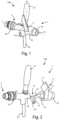
Figure 1 shows a perspective view of the locking device according to the invention, in a first embodiment, installed on a manual dispensing faucet in the dispensing position; -
Figure 2 shows a perspective view of the device ofFigure 1 decoupled from the manual dispensing faucet; -
Figure 3 shows a perspective view of the device ofFigure 1 during assembly to the manual dispensing faucet; -
Figure 4 shows a top view of the device ofFigure 1 ; -
Figures 5a - 5d show respectively a perspective, front, side and top view of the locking device ofFigure 1 ; -
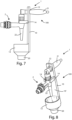
Figure 6 shows a perspective view of the locking device according to the invention, in a second embodiment, installed on a manual dispensing faucet in the dispensing position; -
Figure 7 shows a side view of the device ofFigure 6 ; -
Figure 8 shows a rear perspective view of the device ofFigure 6 ; -
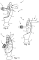
Figure 9 shows a perspective view of the locking device according to the invention, in a third embodiment, installed on a manual dispensing faucet in the dispensing position; -
Figure 10 shows a side view of the device ofFigure 9 ; -
Figure 11 shows a rear perspective view of the device ofFigure 9 ; -
Figure 12 shows a perspective view of a kit according to the invention comprising the first locking device ofFigure 1 in combination with the second locking device ofFigure 6 ; -
Figure 13 shows a rear perspective view of the kit ofFigure 12 ; -
Figure 14 shows a side view of the kit ofFigure 12 ; -
Figure 15 shows a perspective view of a kit according to the invention comprising the first locking device ofFigure 1 in combination with the third locking device ofFigure 9 ; -
Figure 16 shows a rear perspective view of the kit ofFigure 15 ; and -
Figure 17 shows a side view of the kit ofFigure 15 . - Referring to
Figures 1 - 4 and5a - 5d , alocking device 1 according to the invention can be seen, in a first embodiment, for faucets for dispensing beverages, for example water, beer, wine, and/or soft drinks. - In particular, the
locking device 1 makes it possible to lock afaucet 2 in the dispensing position. Afaucet 2 for dispensing beverages generally comprises anozzle 22 for dispensing liquids and alever 21 for allowing/preventing the dispensing of liquids by assuming a dispensing position or a closed position. - The
faucet 2 and thelocking device 1 can form anassembly 100. - The
faucet 2 ofFigure 1 is of the manual type, in other words it is equipped with a dispensinglever 21 having a return spring. When the user acts on thelever 21 by inclining it slightly, it moves to the dispensing position and then, in the absence of action by the user, it automatically returns to the closed position thanks to the spring. - Therefore, the
locking device 1 according to the invention in the first embodiment is capable of independently locking thelever 21 of thefaucet 2 in the locking position without the intervention of a user. - This makes it possible, for example, to leave the
faucet 2 in the dispensing position for a whole night in order to be able to carry out the sanitisation through the passage of a sanitising liquid. - In particular, the
locking device 1 according to the present invention comprises abody 10 on which locking means 11, for locking thelever 21 of thefaucet 2 in the dispensing position, are arranged. In particular, saidbody 10 develops horizontally along a first x-axis and vertically along a second y-axis. - In addition, the
locking device 1 comprises hooking means 14 configured to hook to a portion of thefaucet 2. - Furthermore, said
locking device 1 is configured in such a way that, during use, thehooking means 14 are hooked to thefaucet 2 and the locking means 11 are associated with thelever 21 locking it in the dispensing position. - As can be seen from the figures, said
faucet 2 has a body 24 from which saidnozzle 22 and saidlever 21 extend along opposite directions of a vertical y-axis. In particular, the body 24 of thefaucet 2 extends along a horizontal x-axis, substantially transverse to the vertical y-axis, and has arear portion 25 for the connection to a supply pipe for the liquid to be dispensed, and afront end 23, saidfront portion 23 and saidrear portion 25 being arranged on opposite ends of said body 24 along said horizontal x-axis. Therefore, when said lockingdevice 1 is hooked to saidfaucet 2, it hooks in correspondence with thefront portion 23 of saidfaucet 2. - In addition, the hooking means 14 can comprise a first sensor for detecting the hooking/unhooking of the
locking device 1 from thefaucet 2. In particular, said first sensor can be connected to a logic control unit adapted to start the sanitising cycle when the first sensor communicates to the logic control unit itself that thelocking device 1 has been hooked to thefaucet 2. Therefore, in the event that thelocking device 1 is unhooked by an operator or inadvertently unhooked from thefaucet 2, the sanitising cycle would be interrupted, preventing any spills of the sanitising liquid. - Furthermore, in a first embodiment the locking means are a
first hook 11 having an "L-shaped" profile and comprising a first arm 11' and asecond arm 11". These first 11' and second 11" arms being arranged transversely to each other. - Again, in a first embodiment, the hooking means are a
second hook 14 having an "L-shaped" profile and comprising a first arm 14' and asecond arm 14". Also in this case, these first 14' and second 14" arms being arranged transversely to each other. - The first and
second hooks body 10, with respect to the first horizontal x-axis, and respectivesecond arms 11"; 14" facing each other transversely to the first horizontal x-axis. - In fact, the
locking device 1 is configured in such a way that, during use, thesecond arm 14" of saidsecond hook 14 is hooked to thefaucet 2 and thesecond arm 11" of thefirst hook 11 is hooked to thelever 21, locking it in the beverage dispensing position. -
Such hooks faucet 2 and to themobile lever 21 which is then inclined into the dispensing position. - In addition, the respective first arms 11'; 14' of the first and
second hooks 11; 14 are oriented on axes t11, t14 diverging from each other with respect to the horizontal x-axis of thebody 10 and lying on a respective plane parallel to the vertical XY plane. - Furthermore, the respective
second arms 11"; 14" of the first andsecond hook 11; 14 have abevel 15 at their ending part to facilitate gripping of thefaucet 2 during assembly and/or disassembly. - Again, the
body 10 comprises a throughhole 19 having the centre of symmetry arranged on the horizontal x-axis. In particular, the throughhole 19 allows the housing of oneend 23 of thefaucet 2, so as to improve the hooking of thelocking device 1 to thefaucet 2. - Referring to
Figures 6 - 8 , a second embodiment of thelocking device 1 according to the invention can be seen. - In this embodiment the same numerical references are used for components that are functionally analogous to the first embodiment.
- This
locking device 1 is particularly suitable for locking amanual faucet 2 equipped with a dispensinglever 21 without a return spring. Thisfaucet 2 has alever 21 capable of locking automatically both in the closed position, with thelever 21 substantially parallel to a vertical y-axis, and in the dispensing position, with thelever 21 in a position transverse to this vertical y-axis. - The
locking device 1 according to the present embodiment couples with thelever 21 of thefaucet 2 in the dispensing position, locking it in that position, as it prevents its movement from that position. - In particular, the
locking device 1 comprises abody 10 on which the locking means 12 for locking thelever 21 of saidfaucet 2 in the dispensing position and the hookingmeans 14 for hooking to a portion of saidfaucet 2 are arranged. Said lockingdevice 1 is configured in such a way that, during use, when the hookingmeans 14 are hooked to thefaucet 2, the locking means 12 are associated with thelever 21 locking it in said dispensing position. - In particular, the locking means are a through
hole 12 made on thebody 10. This throughhole 12 has the axis of symmetry parallel to a first horizontal x-axis. - In this second embodiment, the hooking means are a pair of opposing
hooks 14 arranged on thebody 10. In other words, thelocking device 1 is configured in such a way that, during use, when the pair ofhooks 14 is hooked to thefaucet 2, thelever 21 is inserted in the throughhole 12 locking itself in the dispensing position. - Furthermore, each
hook 14 comprises a linear concavity or notch 16, to allow a better coupling of thelocking device 1 with the body of thefaucet 2, in particular with the body of thenozzle 23. - Furthermore, the
body 10 of thelocking device 1 comprises a flat portion 10' which extends beyond the locking means 12 and the hookingmeans 14, advantageously this flat portion 10', acting as a splash guard, makes it possible to prevent the dispersion of drops of liquid during dispensing of the liquid itself and to direct the flow into a container. - In addition to this, the
body 10 comprises a funnel-shapedportion 13 for conveying the liquid dispensed by thenozzle 22 of thefaucet 2. This funnel-shapedportion 13 is arranged on thebody 1 below said locking means 11; 12 and said hookingmeans 14. The funnel-shapedportion 13 has a hole connectable to a pipe for conveying the sanitising liquid into a drain or tank separate from thefaucet 2. - Furthermore, the funnel-shaped
portion 13 can comprise a second sensor inside it, in particular an overflow sensor, to detect the filling level of the funnel-shapedportion 13 and of the pipe connected thereto. In particular, the second sensor can be connected to a logic control unit capable of interrupting the sanitising cycle, when the second sensor detects a filling level higher than a threshold level, which could be indicative of an obstruction of the funnel-shapedportion 13 or of the respective pipe. In addition, the logic control unit can send a notification to a user if the threshold level is exceeded. - Furthermore, in the
lower part 20, in particular in thestem 20, of the funnel-shapedportion 13, a retaining element (not shown) may be present which makes it possible the coupling/decoupling with the drain pipe of the sanitising system. Advantageously, the retention element allows a fluidic connection between the funnel-shapedportion 13 and the pipe, sealing them and preventing any leakage of the sanitising liquid. - In particular, the funnel-shaped
portion 13 is coupled with the lower end of the flat portion 10' of thebody 10, while at the upper end of this flat portion 10' there is the throughhole 12. -
Figures 9-11 show a third embodiment of thelocking device 1 according to the invention. The characteristics functionally analogous to those of the second embodiment will be indicated with the same numerical reference. - In this third embodiment, the funnel-shaped
portion 13 has an opposingflare 17 at the ending portion of said funnel-shapedportion 13. In other words, it has a double opposing flare, a first one with the wider portion facing towards the hookingmeans 14 and locking means 11 of the device in such a way that, during use, it is facing thenozzle 22 of thefaucet 2, and a second opposingflare 17 with the wider portion facing downwards. - This
second flare 17 increases the ergonomics of thelocking device 1 during installation by an operator. - Furthermore, as shown in
Figures 12 - 17 , a kit according to the invention can be provided which includes: - a
first locking device 1 according to the first embodiment and - a
second locking device 1 according to the second or third embodiment. - In the kit, the
body 10 of thefirst locking device 1 provides atubular body 18, wherein thesecond locking device 1 is adapted to be coupled with thefirst locking device 1, by inserting thetubular body 18 of thefirst locking device 1 into the throughhole 12 of thesecond locking device 1. In fact, thistubular body 18 of thefirst locking device 1 has an external diameter smaller than the diameter of the throughhole 12 of the second orthird locking device 1. - Finally, the
locking device 1 can be made of plastic or other materials. In particular, thelocking device 1 can be made using additive prototyping or three-dimensional moulding techniques. - Therefore, the
locking device 1 according to the invention can be used in a system for sanitising faucets for beverages and can provide a tank containing a sanitising solution, as previously described. Such a tank being adapted to be connected to the pipes that form the system to be sanitised and therefore with the respective faucets. - Furthermore, the system can provide a container adapted to be in fluid connection with the nozzle of one or more faucets of the system to be sanitised.
- Thanks to the locking device according to the invention, the faucet assumes a dispensing position and the sanitising solution flows from the faucet to then be collected in a drain or in said container.
- Again, as previously described, the system can comprise a logic control unit and one or more sensors connected to said locking device.
- In the foregoing the preferred embodiments have been described and variants of the present invention have been suggested, but it should be understood that those skilled in the art will be able to make modifications and changes without thereby departing from the relative scope of protection, as defined by the attached claims.
Claims (17)
- A locking device (1) for a beverage dispensing faucet (2), said faucet (2) comprising a nozzle (22) for dispensing liquids and a lever (21) for allowing/preventing the dispensing of said liquids by assuming a dispensing position or a closed position,
said locking device (1) being characterised in that it comprises a body (10) on which locking means (11; 12) for locking said lever (21) of said faucet (2) in the dispensing position and hooking means (14) for hooking to a portion of said faucet (2) are arranged, said locking device (1) being configured in such a way that, during use, when said hooking means (14) are hooked to said faucet (2), said locking means (11; 12) are associated with said lever (21) locking it in said dispensing position. - The locking device (1) according to the previous claim, wherein said hooking means (14) comprise a first sensor configured to detect the hooking/unhooking of said locking device (1) to/from said faucet (2).
- The locking device (1) according to claim 1 or 2, wherein said locking means are a first hook (11) having an "L-shaped" profile, wherein said hooking means are a second hook (14) having an "L-shaped" profile, said first and second hooks (11, 14) having their respective first arms (11'; 14') fixed on opposite sides of said body (10), with respect to a first horizontal (x) axis, and their respective second arms (11 "; 14") facing each other transversely to said first horizontal (x) axis, said locking device (1) being configured in such a way that, during use, when the second arm (14") of said second hook (14) is hooked to said faucet (2), the second arm (11") of said first hook (11) is hooked to said lever (21) locking it in said dispensing position.
- The locking device (1) according to claim 3, wherein said respective first arms (11'; 14') of said first and second hooks (11; 14) are oriented on axes (t11, t14) mutually diverging with respect to the first horizontal (x) axis of said body (10) and lying on respective planes parallel to the vertical (XY) plane of said body (10).
- The locking device (1) according to any one of claims 3 or 4, wherein said respective second arms (11"; 14") have a bevel (15) at their ending part to facilitate gripping.
- The locking device (1) according to any one of claims 3-5, wherein said body (10) comprises a through hole (19) having the centre of symmetry arranged on said first horizontal (x) axis, said hole (19) being adapted to house one end (23) of said faucet (2).
- The locking device (1) according to claim 1 or 2, wherein said locking means are a through hole (12) made on said body (10), wherein said hooking means are a pair of opposing hooks (14) arranged on said body (10), said locking device (1) being configured in such a way that, during use, when said pair of hooks (14) is hooked to said faucet (2), said lever (21) is inserted in said through hole (12) locking itself in said dispensing position.
- The locking device (1) according to the preceding claim, wherein said pair of hooks (14) comprises a linear concavity (16).
- The locking device (1) according to any one of the preceding claims, wherein said body (10) comprises a flat portion (10') extending beyond said locking means (11; 12) and hooking means (14), said flat portion (10') being configured to direct the flow of a sanitising liquid in a tank, preventing the dispersion of drops of said liquid.
- The locking device (1) according to any one of the preceding claims, wherein said body (10) comprises a funnel-shaped portion (13) for conveying the liquid dispensed from the nozzle (22) of said faucet (2), said funnel-shaped portion (13) being arranged on said body (10) below said locking means (11; 12) and said hooking means (14).
- The locking device (1) according to the preceding claim, wherein the lower part or stem (20) of said funnel-shaped portion (13) comprises a retaining device configured to allow the coupling/decoupling of said funnel-shaped portion (13) with a drain pipe.
- The locking device (1) according to claim 10 or 11, wherein said funnel-shaped portion (13) comprises a second sensor configured to detect the filling level of said funnel-shaped portion (13).
- A kit comprising a first locking device (1) according to any one of claims 3-6 and a second locking device (1) according to claim 7 or 8 and any one of claims 9 - 12, wherein the body (10) of said first locking device (1) provides a tubular body (18), wherein said second locking device (1) is adapted to be coupled with said first locking device (1) by inserting said tubular body (18) of said first locking device (1) in said through hole (12) of said second locking device (1).
- Use of the locking device (1) according to any one of claims 1 - 12 for locking the lever (21) of a liquid beverage dispensing faucet (2) in the dispensing position.
- A system for sanitising a faucet (2) for dispensing beverages, said system comprising- a logic control unit,- a locking device (1) according to any one of claims 2 or 12.
- An assembly (100) comprising a beverage dispensing faucet (2), said faucet (2) comprising a nozzle (22) for dispensing liquids, and a lever (21) to allow/prevent the dispensing of said liquids by assuming a dispensing position or a closed position, said assembly (100) further comprising a locking device (1) according to any one of claims 1 - 12 , said assembly (100) being configured in such a way that when said hooking means (14) of said locking device (1) are hooked to said faucet (2), said locking means (11; 12) act on said lever (21) of said faucet (1) which assumes said dispensing position for the continuous dispensing of liquids.
- The assembly (100) according to the preceding claim, wherein said faucet (2) has a body (24) from which said nozzle (22) and said lever (21) extend along opposite directions of a vertical (y) axis, wherein said body (24) extends along a horizontal (x) axis, substantially transverse to the vertical (y) axis and having a rear portion (25) for the connection to a supply pipe for the liquid to be dispensed, and a front end (23), said front portion (23) and said rear portion (25) being arranged on opposite ends of said body (24) along said horizontal (x) axis, wherein when said locking device (1) is hooked to said faucet (2), it hooks at the front portion (23) of said faucet (2).
Applications Claiming Priority (1)
| Application Number | Priority Date | Filing Date | Title |
|---|---|---|---|
| IT202200018540 | 2022-09-12 |
Publications (3)
| Publication Number | Publication Date |
|---|---|
| EP4335813A1 true EP4335813A1 (en) | 2024-03-13 |
| EP4335813C0 EP4335813C0 (en) | 2025-11-19 |
| EP4335813B1 EP4335813B1 (en) | 2025-11-19 |
Family
ID=84362406
Family Applications (1)
| Application Number | Title | Priority Date | Filing Date |
|---|---|---|---|
| EP23183911.9A Active EP4335813B1 (en) | 2022-09-12 | 2023-07-06 | Locking device for beverage dispensing faucets |
Country Status (1)
| Country | Link |
|---|---|
| EP (1) | EP4335813B1 (en) |
Citations (4)
| Publication number | Priority date | Publication date | Assignee | Title |
|---|---|---|---|---|
| GB2179628A (en) * | 1985-08-09 | 1987-03-11 | Walter Patrick Twomey | Improvements relating to beer dispensing fonts |
| US5394715A (en) * | 1993-06-07 | 1995-03-07 | Controles B.V.L. Ltee | Retaining mechanism for a liquid dispensing apparatus valve |
| US5750905A (en) * | 1997-03-06 | 1998-05-12 | Eaton Corporation | Beverage dispenser tap cover with position sensing switch |
| US20040238569A1 (en) * | 2003-05-28 | 2004-12-02 | Robinson Jon J. | Beverage tower tap lock |
-
2023
- 2023-07-06 EP EP23183911.9A patent/EP4335813B1/en active Active
Patent Citations (4)
| Publication number | Priority date | Publication date | Assignee | Title |
|---|---|---|---|---|
| GB2179628A (en) * | 1985-08-09 | 1987-03-11 | Walter Patrick Twomey | Improvements relating to beer dispensing fonts |
| US5394715A (en) * | 1993-06-07 | 1995-03-07 | Controles B.V.L. Ltee | Retaining mechanism for a liquid dispensing apparatus valve |
| US5750905A (en) * | 1997-03-06 | 1998-05-12 | Eaton Corporation | Beverage dispenser tap cover with position sensing switch |
| US20040238569A1 (en) * | 2003-05-28 | 2004-12-02 | Robinson Jon J. | Beverage tower tap lock |
Also Published As
| Publication number | Publication date |
|---|---|
| EP4335813C0 (en) | 2025-11-19 |
| EP4335813B1 (en) | 2025-11-19 |
Similar Documents
| Publication | Publication Date | Title |
|---|---|---|
| US6296626B1 (en) | Eye wash station | |
| US5090440A (en) | Line cleaning apparatus | |
| KR100324552B1 (en) | Sealed actuator probe assembly for a bottled water station | |
| US5839454A (en) | Automatic detergent dispenser | |
| US11116363B2 (en) | Dispensing system | |
| JPH05505373A (en) | Chemical solution dispensing handling system | |
| US9731307B2 (en) | Metered dosing bottle | |
| US8925763B2 (en) | Beverages dispenser and a method for dispensing beverages | |
| EP4335813A1 (en) | Locking device for beverage dispensing faucets | |
| US8069866B2 (en) | Apparatus and method for cleaning beverage lines | |
| US3410303A (en) | Cover for a dispensing faucet | |
| US6341385B1 (en) | Toilet bowl fluid dispensing system | |
| GB2306303A (en) | Detergent dispenser | |
| RU206709U1 (en) | WATER TROLLEY FOR ON-BOARD KITCHEN AND ATTACHMENT SECTION FOR IT | |
| CN108331110B (en) | Intelligent toilet | |
| US20070006370A1 (en) | Urinal | |
| JP7210160B2 (en) | urinal system | |
| EP3771686B1 (en) | Foam on beer (fob) detector | |
| KR102288480B1 (en) | Dispenser for beverage | |
| JP5618692B2 (en) | Sanitizer | |
| JP4617605B2 (en) | Cleaning liquid supply port structure | |
| CN219895393U (en) | Drip-proof structure and drink machine | |
| US5339858A (en) | Device for restoring a fluid level in a fluid receptacle | |
| CN224205913U (en) | A pet water fountain with automatic water changing function | |
| RU2271419C2 (en) | Mixer |
Legal Events
| Date | Code | Title | Description |
|---|---|---|---|
| PUAI | Public reference made under article 153(3) epc to a published international application that has entered the european phase |
Free format text: ORIGINAL CODE: 0009012 |
|
| STAA | Information on the status of an ep patent application or granted ep patent |
Free format text: STATUS: THE APPLICATION HAS BEEN PUBLISHED |
|
| AK | Designated contracting states |
Kind code of ref document: A1 Designated state(s): AL AT BE BG CH CY CZ DE DK EE ES FI FR GB GR HR HU IE IS IT LI LT LU LV MC ME MK MT NL NO PL PT RO RS SE SI SK SM TR |
|
| STAA | Information on the status of an ep patent application or granted ep patent |
Free format text: STATUS: REQUEST FOR EXAMINATION WAS MADE |
|
| 17P | Request for examination filed |
Effective date: 20240912 |
|
| RBV | Designated contracting states (corrected) |
Designated state(s): AL AT BE BG CH CY CZ DE DK EE ES FI FR GB GR HR HU IE IS IT LI LT LU LV MC ME MK MT NL NO PL PT RO RS SE SI SK SM TR |
|
| GRAP | Despatch of communication of intention to grant a patent |
Free format text: ORIGINAL CODE: EPIDOSNIGR1 |
|
| STAA | Information on the status of an ep patent application or granted ep patent |
Free format text: STATUS: GRANT OF PATENT IS INTENDED |
|
| RIC1 | Information provided on ipc code assigned before grant |
Ipc: F16K 35/10 20060101ALI20250311BHEP Ipc: F16K 35/06 20060101ALI20250311BHEP Ipc: B67D 1/14 20060101ALI20250311BHEP Ipc: B67D 1/08 20060101ALI20250311BHEP Ipc: B67D 1/07 20060101AFI20250311BHEP |
|
| INTG | Intention to grant announced |
Effective date: 20250331 |
|
| GRAS | Grant fee paid |
Free format text: ORIGINAL CODE: EPIDOSNIGR3 |
|
| GRAA | (expected) grant |
Free format text: ORIGINAL CODE: 0009210 |
|
| STAA | Information on the status of an ep patent application or granted ep patent |
Free format text: STATUS: THE PATENT HAS BEEN GRANTED |
|
| AK | Designated contracting states |
Kind code of ref document: B1 Designated state(s): AL AT BE BG CH CY CZ DE DK EE ES FI FR GB GR HR HU IE IS IT LI LT LU LV MC ME MK MT NL NO PL PT RO RS SE SI SK SM TR |
|
| REG | Reference to a national code |
Ref country code: CH Ref legal event code: F10 Free format text: ST27 STATUS EVENT CODE: U-0-0-F10-F00 (AS PROVIDED BY THE NATIONAL OFFICE) Effective date: 20251119 Ref country code: GB Ref legal event code: FG4D |
|
| REG | Reference to a national code |
Ref country code: DE Ref legal event code: R096 Ref document number: 602023008703 Country of ref document: DE |
|
| REG | Reference to a national code |
Ref country code: IE Ref legal event code: FG4D |
|
| U01 | Request for unitary effect filed |
Effective date: 20251219 |
|
| U07 | Unitary effect registered |
Designated state(s): AT BE BG DE DK EE FI FR IT LT LU LV MT NL PT RO SE SI Effective date: 20260105 |
|
| PG25 | Lapsed in a contracting state [announced via postgrant information from national office to epo] |
Ref country code: ES Free format text: LAPSE BECAUSE OF FAILURE TO SUBMIT A TRANSLATION OF THE DESCRIPTION OR TO PAY THE FEE WITHIN THE PRESCRIBED TIME-LIMIT Effective date: 20251119 |
|
| PG25 | Lapsed in a contracting state [announced via postgrant information from national office to epo] |
Ref country code: NO Free format text: LAPSE BECAUSE OF FAILURE TO SUBMIT A TRANSLATION OF THE DESCRIPTION OR TO PAY THE FEE WITHIN THE PRESCRIBED TIME-LIMIT Effective date: 20260219 |
|
| PG25 | Lapsed in a contracting state [announced via postgrant information from national office to epo] |
Ref country code: HR Free format text: LAPSE BECAUSE OF FAILURE TO SUBMIT A TRANSLATION OF THE DESCRIPTION OR TO PAY THE FEE WITHIN THE PRESCRIBED TIME-LIMIT Effective date: 20251119 |
|
| PG25 | Lapsed in a contracting state [announced via postgrant information from national office to epo] |
Ref country code: RS Free format text: LAPSE BECAUSE OF FAILURE TO SUBMIT A TRANSLATION OF THE DESCRIPTION OR TO PAY THE FEE WITHIN THE PRESCRIBED TIME-LIMIT Effective date: 20260219 |
|
| PG25 | Lapsed in a contracting state [announced via postgrant information from national office to epo] |
Ref country code: IS Free format text: LAPSE BECAUSE OF FAILURE TO SUBMIT A TRANSLATION OF THE DESCRIPTION OR TO PAY THE FEE WITHIN THE PRESCRIBED TIME-LIMIT Effective date: 20260319 |
|
| PG25 | Lapsed in a contracting state [announced via postgrant information from national office to epo] |
Ref country code: PL Free format text: LAPSE BECAUSE OF FAILURE TO SUBMIT A TRANSLATION OF THE DESCRIPTION OR TO PAY THE FEE WITHIN THE PRESCRIBED TIME-LIMIT Effective date: 20251119 |