EP4335804A1 - A driving device for an escalator - Google Patents
A driving device for an escalator Download PDFInfo
- Publication number
- EP4335804A1 EP4335804A1 EP23195014.8A EP23195014A EP4335804A1 EP 4335804 A1 EP4335804 A1 EP 4335804A1 EP 23195014 A EP23195014 A EP 23195014A EP 4335804 A1 EP4335804 A1 EP 4335804A1
- Authority
- EP
- European Patent Office
- Prior art keywords
- driving
- spindle
- cylindrical section
- gear
- spacer
- Prior art date
- Legal status (The legal status is an assumption and is not a legal conclusion. Google has not performed a legal analysis and makes no representation as to the accuracy of the status listed.)
- Granted
Links
Images





Classifications
-
- B—PERFORMING OPERATIONS; TRANSPORTING
- B66—HOISTING; LIFTING; HAULING
- B66B—ELEVATORS; ESCALATORS OR MOVING WALKWAYS
- B66B23/00—Component parts of escalators or moving walkways
- B66B23/02—Driving gear
-
- B—PERFORMING OPERATIONS; TRANSPORTING
- B66—HOISTING; LIFTING; HAULING
- B66B—ELEVATORS; ESCALATORS OR MOVING WALKWAYS
- B66B23/00—Component parts of escalators or moving walkways
- B66B23/02—Driving gear
- B66B23/04—Driving gear for handrails
Definitions
- the present disclosure relates to a driving device, in particular to a driving device for escalator.
- This driving device is used to drive the step assembly and handrail belt assembly of the escalator.
- the maximum lifting height that the existing escalator drive device can meet is only 28 meters or less, which can no longer meet market demand.
- the number and/or power of the driving motors can only be increased.
- a driving device for escalator comprising a first driving motor, a second driving motor, a third driving motor, a fourth driving motor, a driving spindle and a handrail belt spindle, wherein the first driving motor and the second driving motor are connected with a first gear box, and the third driving motor and the fourth driving motor are connected with a second gear box, the driving torque of the first driving motor and the second driving motor is transmitted to the driving spindle through the first gear box, and the driving torque of the third driving motor and the fourth driving motor are transmitted to the driving spindle through the second gear box, wherein the driving device further comprises at least one fifth driving motor and at least one sixth driving motor.
- the fifth driving motor and the sixth driving motor are connected with at least one third gear box.
- the driving torque of the fifth driving motor and the sixth driving motor is transmitted to the driving spindle and the handrail belt spindle through the third gear box.
- the fifth driving motor is arranged between the driving spindle and the handrail belt spindle.
- the handrail belt spindle is arranged between the fifth driving motor and the sixth driving motor.
- the third gear box is disposed between the first gear box and the second gear box and is disposed closer to the first gear box than the second gear box.
- the fifth driving motor and the sixth driving motor are both located between the handrail belt assemblies arranged on two axial ends of the handrail belt spindle.
- the third gear box comprises an output gear, a first input gear, a handrail belt spindle gear and a second input gear which are arranged in a housing of the third gear box.
- the fifth driving motor drives the first input gear.
- the sixth driving motor drives the second input gear.
- the first input gear is matched with the output gear and the handrail belt spindle gear at the same time.
- the second input gear is matched with the handrail belt spindle gear.
- the driving torque of the fifth driving motor is transmitted to the driving spindle through the input gear and to the handrail belt spindle through the handrail belt spindle gear.
- the driving torque of the sixth driving motor is transmitted to the handrail belt spindle through the handrail belt spindle gear.
- a spline structure is arranged on the outer circumferential surface of a part of handrail belt spindle.
- the handrail belt spindle gear is provided with a handrail gear through hole, and a spline structure is arranged on the inner circumferential surface of the handrail gear through hole.
- the handrail belt spindle is fitted in the handrail gear through hole, and the spline structure on the inner circumferential surface of the handrail gear through hole is fitted with the spline structure on the outer circumferential surface of the part of the handrail belt spindle.
- the handrail belt assembly are arranged on two axial ends of the handrail belt spindle.
- the rotation of the handrail belt spindle drives the handrail belt assembly to move.
- the handrail belt spindle is also provided with a third sealing piece and a fourth sealing piece.
- the third sealing piece and the fourth sealing piece are respectively and fixedly connected to two sides of the housing of the third gear box through fasteners.
- a spline structure is arranged on the outer circumferential surface of the first axial end of the driving spindle.
- the output gear of the first gear box is provided with an output gear through hole, and the inner circumferential surface of the output gear through hole is provided with a spline structure.
- the first axial end of the driving spindle is fitted in the output gear through hole of the output gear of the first gearbox, and the spline structure of the first axial end of the driving spindle is fitted with the spline structure of the output gear through hole.
- a first axial protrusion extending outward from the first axial end of the driving spindle.
- a first axial end cap is fixedly fitted on the first axial protrusion through a fastener and abuts against the output gear of the first gear box.
- a first annular recess is arranged on the driving spindle adjacent to the first axial end of the driving spindle.
- a first cylindrical section is arranged on the driving spindle adjacent to the first annular recess of the driving spindle.
- a first ferrule is arranged on the outer circumferential surface of the first cylindrical section, and the first ferrule is located between an extended part of the output gear of the first gearbox and the outer circumferential surface of the first cylindrical section.
- a first double-row roller bearing is arranged on the first cylindrical section.
- a first spacer is arranged between an inner ring of the first double-row roller bearing and the extended part of the output gear of the first gear box.
- the extended part of the output gear of the first gear box abuts against the inner ring of the first double-row roller bearing through the first spacer.
- a second cylindrical section is arranged on the driving spindle adjacent to the first cylindrical section of the driving spindle.
- a first step sprocket assembly is fitted on the second cylindrical section.
- the first step sprocket assembly comprises a step flange and a step sprocket, wherein the step sprocket is connected to the step flange through a fastener and is matched with the steps of the escalator.
- the step flange is provided with a step flange through hole.
- the step flange is matched with the spline structure arranged on the outer circumferential surface of the second cylindrical section through the spline structure arranged on the inner circumferential surface of the step flange through hole.
- a second ferrule is arranged on the outer circumferential surface of the first cylindrical section, and the second ferrule is located between the step flange and the outer circumferential surface of the first cylindrical section.
- a second spacer is arranged between the inner ring of the first double-row roller bearing and the step flange.
- the inner ring of the first double-row roller bearing abuts against the step flange through the second spacer.
- a third cylindrical section is arranged on the driving spindle adjacent to the second cylindrical section of the driving spindle.
- a ring-shaped third spacer is arranged on the outer circumferential surface of the third cylindrical section.
- Two single-row rolling bearings are respectively arranged on the outer circumferential surfaces of the two axial ends of the third spacer.
- a first steering plate mounting part is arranged on the outer rings of the two single-row rolling bearings.
- a first steering plate is installed on the first steering plate mounting part through convex-concave fit, and one of the step runner of the escalator is rolling fitted on the first steering plate.
- the stepped flange abuts against the inner ring of one of the single-row rolling bearings and abuts against the third spacer.
- a first stopper is connected to the first steering plate mounting part through a fastener and extends to the rolling body of another single-row rolling bearing along the radial direction of the third cylindrical section, thereby blocking the outer ring of the other single-row rolling bearing in the axial direction.
- a first mounting part boss is arranged on the first steering plate mounting part.
- a spacer boss facing the first mounting part boss is arranged on the third spacer.
- the outer rings of the two single-row rolling bearings respectively abut against the two axial ends of the first mounting part boss.
- the inner rings of the two single-row rolling bearings respectively abut against the two axial ends of the spacer boss.
- a fourth cylindrical section and a fifth cylindrical section are sequentially arranged on the driving spindle adjacent to the third cylindrical section of the driving spindle.
- a fourth spacer in the shape of a ring is arranged on an outer circumferential surface of the fourth cylindrical section.
- a first axial end of the fourth spacer is fitted on the third cylindrical section.
- a second axial end of the fourth spacer is fitted on the fifth cylindrical section.
- the inner ring of the other single-row rolling bearing and the third spacer abut against the first axial end of the fourth spacer.
- the output gear of the third gear box abuts against a step portion provided on the second axial end of the fourth spacer.
- a first closing part is also arranged on the outer surface of the fourth spacer.
- the first closing member is fixedly connected to the first side of the housing of the third gear box by fastener.
- a sixth cylindrical section is arranged on the driving spindle adjacent to the fifth cylindrical section of the driving spindle.
- a spline structure is arranged on the outer circumferential surface of the sixth cylindrical section.
- the output gear of the third gearbox is provided with an output gear through hole, and the inner circumferential surface of the output gear through hole of the output gear of the third gearbox is provided with a spline structure.
- the sixth cylindrical section of the driving spindle is splined in the output gear through hole of the output gear of the third gearbox.
- a second annular recess is arranged on the driving spindle adjacent to the sixth cylindrical section of the driving spindle.
- a seventh cylindrical section and an eighth cylindrical section are sequentially arranged on the driving spindle adjacent to the second annular recess of the driving spindle.
- the output gear of the third gear box is fitted on the seventh cylindrical section and abuts against a step portion formed between the seventh cylindrical section and the eighth cylindrical section.
- a second closing part is also arranged on the outer surface of the eighth cylindrical section.
- the second closing member is fixedly connected to the second side of the housing of the third gear box by fastener.
- a spline structure is arranged on the outer circumferential surface of the second axial end of the driving spindle.
- the output gear of the second gearbox is provided with an output gear through hole, and the inner circumferential surface of the output gear through hole is provided with a spline structure.
- the second axial end of the driving spindle is fitted in the output gear through hole of the output gear of the second gearbox, and the spline structure of the second axial end of the driving spindle is fitted with the spline structure of the output gear through hole.
- a second axial protrusion extending outward from the second axial end of the driving spindle.
- a second axial end cap is fixedly fitted on the second axial protrusion through a fastener and abuts against the output gear of the second gearbox.
- a third annular recess is arranged on the driving spindle adjacent to the second axial end of the driving spindle.
- a ninth cylindrical section is arranged on the driving spindle adjacent to the third annular recess of the driving spindle.
- a third collar is arranged on the outer circumferential surface of the ninth cylindrical section, and the third collar is located between an extended part of the output gear of the second gearbox and the outer circumferential surface of the ninth cylindrical section.
- a second double-row roller bearing is arranged on the ninth cylindrical section.
- a fifth spacer is arranged between the inner ring of the second double-row roller bearing and the extended part of the output gear of the second gearbox.
- a tenth cylindrical section is arranged on the driving spindle adjacent to the ninth cylindrical section of the driving spindle.
- a second step sprocket assembly is fitted on the tenth cylindrical section.
- the second step sprocket assembly comprises a step flange and a step sprocket, wherein the step sprocket is connected to the step flange through a fastener and is matched with the steps of the escalator.
- the step flange is provided with a step flange through hole.
- the step flange is matched with the spline structure arranged on the outer circumferential surface of the tenth cylindrical section through the spline structure arranged on the inner circumferential surface of the step flange through hole.
- a fourth collar is also arranged on the outer circumferential surface of the ninth cylindrical section, and the fourth collar is located between the step flange and the outer circumferential surface of the ninth cylindrical section.
- a sixth spacer is arranged between the inner ring of the second double-row roller bearing and the step flange of the second step sprocket assembly.
- the inner ring of the second double-row roller bearing abuts against the step flange of the second step sprocket assembly through the sixth spacer.
- an eleventh cylindrical section is arranged on the driving spindle adjacent to the tenth cylindrical section of the driving spindle.
- An annular seventh spacer is arranged on the outer circumferential surface of the eleventh cylindrical section.
- Two single-row rolling bearings are respectively arranged on the outer circumferential surfaces of the two axial ends of the seventh spacer.
- a second steering plate mounting part is arranged on the outer rings of the two single-row rolling bearings.
- a second steering plate is installed on the second steering plate mounting part through convex-concave fit, and another step runner of the escalator steps is rolled and matched on the second steering plate.
- the stepped flange abuts against the inner ring of one of the single-row rolling bearings and abuts against the seventh spacer.
- a second stopper is connected to the second steering plate mounting part through a fastener and extends to the rolling body of another single-row rolling bearing along the radial direction of the eleventh cylindrical section, thereby blocking the outer ring of the other single-row rolling bearing in the axial direction.
- a second mounting part boss is arranged on the second steering plate mounting part.
- a spacer boss facing the second mounting part boss is arranged on the seventh spacer.
- the outer rings of the two single-row rolling bearings respectively abut against the two axial ends of the second mounting part boss.
- the inner rings of the two single-row rolling bearings respectively abut against the two axial ends of the spacer boss.
- the seventh spacer abuts against a step portion formed between the eleventh cylindrical section of the driving spindle and the eighth cylindrical section of the driving spindle.
- the first driving motor and the second driving motor are connected with the first gear box through a gear transmission mechanism.
- the third driving motor and the fourth driving motor are connected with the second gear box through a gear transmission mechanism.
- the fifth driving motor and the sixth driving motor are connected with said at least one third gear box through a gear transmission mechanism.
- the fifth and sixth driving motors are added to the driving device of the escalator, so that the total lifting power of the driving device is improved, and the requirement of increasing the lifting height can be met.
- each original driving motor remains unchanged, and there is no need to transform the original space for accommodating the original driving motors.
- the added fifth driving motor is arranged between the driving spindle and the handrail belt spindle, thus making full use of the original unused space between the driving spindle and the handrail belt spindle.
- the handrail belt spindle is arranged between and driven by the fifth and sixth driving motors, thereby increasing the driving torque that can be applied to the handrail belt spindle.
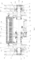
- Figure 1 shows a three-dimensional schematic diagram of a driving device for an escalator according to an embodiment of the present disclosure, wherein the driving device comprises a first driving motor 1, a second driving motor 2, a third driving motor 3, a fourth driving motor 4, a driving spindle 7, and a handrail belt spindle 8.
- the first driving motor 1 and the second driving motor 2 are connected to a first gearbox 10 through their respective planetary gear trains (not shown).
- the third driving motor and the fourth driving motor are connected to a second gearbox 11 through their respective planetary gear trains.
- each planetary gear train can also be set in corresponding gearboxes.
- the driving torques of the first and second driving motors 1 and 2 are transmitted to the driving spindle 7 through the first gear box 10, and the driving torques of the third and fourth driving motors 3 and 4 are transmitted to the driving spindle 7 through the second gear box 11.
- the first gear box 10 and the second gear box 11 each include a respective input gear, an intermediate transmission gear (not shown) and an output gear.
- the first driving motor 1 and the second driving motor 2 are engaged with the corresponding input gears of the first gear box 10 and the second gear box through their respective planetary gear trains, and the driving torque is transmitted to the corresponding output gears through the corresponding intermediate transmission gears, and then to the driving spindle 7.
- the driving device further includes a fifth driving motor 5 and a sixth driving motor 6.
- the fifth driving motor 5 and the sixth driving motor 6 are connected with the third gear box 12 through respective planetary gear trains.
- the driving torques of the fifth driving motor 5 and the sixth driving motor 6 are transmitted to the driving spindle 7 and the handrail belt spindle 8 through the third gear box 12.
- the fifth driving motor 5 is arranged between the driving spindle 7 and the handrail belt spindle 8.
- the handrail belt spindle 8 is arranged between the fifth driving motor 5 and the sixth driving motor 6.
- the third gear box 12 is disposed between the first gear box 10 and the second gear box 11 and is disposed closer to the first gear box 10 than the second gear box 11.
- the driving spindle 7 and the handrail spindle 8 are arranged in parallel with each other.
- the fifth driving motor 5 and the sixth driving motor 6 are both located between the handrail belt assemblies 9 provided at both axial ends of the handrail belt spindle 8.
- Fig. 1 also shows six braking devices acting on the first to sixth driving motors respectively.
- a spline structure is provided on the outer circumferential surface of a first axial end 7-1 of the driving spindle 7.
- the output gear 10-1 of the first gear box 10 has an output gear through hole 10-2, and a spline structure is provided on the inner circumferential surface of the output gear through hole 10-2.
- the first axial end 7-1 of the driving spindle 7 is fitted into the output gear through hole 10-2 of the output gear 10-1 of the first gear box 10, and the spline structure of the first axial end 7-1 of the driving spindle 7 is fitted with the spline structure of the output gear through hole 10-2.
- a first axial protrusion 7-2 extends outward from the first axial end 7-1 of the driving spindle 7.
- a first axial end cap 7-3 is fixedly fitted on the first axial protrusion 7-2 by fasteners and abuts against the output gear 10-1 of the first gear box 10.
- a first annular recess 7-4 is provided on the driving spindle 7 adjacent to the first axial end 7-1 of the driving spindle 7.
- a first cylindrical section 7-5 is provided on the driving spindle 7 adjacent to the first annular recess 7-4 of the driving spindle 7.
- a first ferrule 7-6 is provided, which is located between the axial extension of the output gear 10-1 of the first gear box 10 and the outer circumferential surface of the first cylindrical section 7-5.
- the output gear 10-1 is supported by the driving spindle 7 at its two ends along the axial direction of the driving spindle 7 (for example, one end is supported by the first ferrule 7-6 and the other end is supported by the first axial end cap 7-3 provided on the driving spindle 7), so that the spline structure of the first axial end 7-1 of the driving spindle 7 does not bear radial pressure, but only bears driving torque.
- a first double-row roller bearing 13 is provided on the first cylindrical section 7-5.
- a first spacer 7-7 is provided between an inner ring 13-1 of the first double-row roller bearing 13 and the extended portion of the output gear 10-1 of the first gear box 10.
- the extended portion of the output gear 10-1 of the first gear box 10 abuts against the inner ring 13-1 of the first double-row roller bearing 13 through the first spacer 7-7.
- a second cylindrical section 7-8 is provided on the driving spindle 7 adjacent to the first cylindrical section 7-5 of the driving spindle 7.
- a first step sprocket assembly 14 is fitted on the second cylindrical section 7-8.
- the first step sprocket assembly 14 includes a step flange 14-1 and a step sprocket 14-2, wherein the step sprocket 14-2 is connected to the step flange 14-1 through fasteners and cooperates with the steps 15 of the escalator.
- the step flange 14-1 has a step flange through hole 14-3.
- the step flange 14-1 is matched with the spline structure provided on the outer circumferential surface of the second cylindrical section 7-8 through the spline structure provided on the inner circumferential surface of the step flange through hole 14-3.
- a second ferrule 7-9 is also provided on the outer circumferential surface of the first cylindrical section 7-5, and the second ferrule 7-9 is located between the step flange 14-1 and the outer circumferential surface of the first cylindrical section 7-5.
- a second spacer 7-10 is provided between the inner ring 13-1 of the first double-row roller bearing 13 and the stepped flange 14-1.
- the inner ring 13-1 of the first double-row roller bearing 13 abuts against the step flange 14-1 through the second spacer 7-10.
- a third cylindrical section 7-11 is provided on the driving spindle 7 adjacent to the second cylindrical section 7-8 of the driving spindle 7.
- An annular third spacer 7-12 is provided on an outer circumferential surface of the third cylindrical section 7-11.
- Two single-row rolling bearings 16 are respectively provided on the outer circumferential surfaces of the two axial ends of the third spacers 7-12.
- a first steering plate mounting portion 17 is provided on the outer ring 16-1 of the two single-row rolling bearings 16.
- a first steering plate 18 is mounted on the first steering plate mounting portion 17 through convex-concave fit, and one of the step wheels (not shown) of the steps 15 of the escalator is rolling fitted on the first steering plate 18.
- the stepped flange 14-1 abuts against the inner ring 16-2 of one of the single-row rolling bearings 16 and abuts against the third spacer 7-12.
- a first stopper 7-13 is connected to the first steering plate mounting portion 17 by fasteners and extends to the rolling body of another single-row rolling bearing 16 along the radial direction of the third cylindrical section 7-11, thereby blocking the outer ring 16-1 of the other single-row rolling bearing 16 in the axial direction.
- the stepped flange 14-1 is supported by the driving spindle 7 at its two ends along the axial direction of the driving spindle 7 (for example, one end is supported by the second ferrule 7-9 and the other end is supported by the outer circumferential surface of the third cylindrical section 7-11), so that the spline structure provided on the outer circumferential surface of the second cylindrical section 7-8 does not bear radial pressure, but only bears driving torque.
- the first steering plate mounting portion 17 is provided with a first mounting portion boss 17-1.
- the third spacer 7-12 is provided with a spacer boss 7-12-1 facing the first mounting boss 17-1.
- the outer rings 16-1 of the two single-row rolling bearings 16 respectively abut against two axial ends of the first mounting boss 17-1.
- the inner rings 16-2 of the two single-row rolling bearings 16 abut against two axial ends of the spacer boss 7-12-1, respectively.
- a fourth cylindrical section 7-14 and a fifth cylindrical section 7-15 are sequentially provided on the driving spindle 7 adjacent to the third cylindrical section 7-11 of the driving spindle 7.
- a ring-shaped fourth spacer 7-16 is provided on the outer circumferential surface of the fourth cylindrical section 7-14.
- the first axial end of the fourth spacer 7-16 is fitted on the third cylindrical section 7-11.
- a second axial end of the fourth spacer 7-16 is fitted on the fifth cylindrical section 7-15.
- the inner ring 16-2 of the other single-row rolling bearing 16 and the third spacer 7-12 abut on the first axial end of the fourth spacer 7-16.
- the output gear 12-1 of the third gear box 12 abuts against a step portion 7-16-1 provided on the second axial end of the fourth spacer 7-16.
- a first closing member 19 is also provided on the outer surface of the fourth spacer 7-16.
- the first closing member 19 is fixedly connected to a first side 12-3 of the housing 12-2 of the third gear box 12 by fasteners.
- a sixth cylindrical section 7-17 is provided on the driving spindle 7 adjacent to the fifth cylindrical section 7-15 of the driving spindle 7.
- a spline structure is provided on an outer circumferential surface of the sixth cylindrical section 7-17.
- the output gear 12-1 of the third gear box 12 has an output gear through hole 12-4, and a spline structure is provided on the inner circumferential surface of the output gear through hole 12-4 of the output gear 12-1 of the third gear box 12.
- the sixth cylindrical section 7-17 of the driving spindle 7 is splined in the output gear through hole 12-4 of the output gear 12-1 of the third gear box 12.
- a second annular recess 7-18 is provided on the driving spindle 7 adjacent to the sixth cylindrical section 7-17 of the driving spindle 7.
- a seventh cylindrical section 7-19 and an eighth cylindrical section 7-20 are sequentially arranged on the driving spindle 7 adjacent to the second annular recess 7-18 of the driving spindle 7.
- the output gear 12-1 of the third gear box 12 is fitted on the seventh cylindrical section 7-19 and abuts against a step portion 7-21 formed between the seventh cylindrical section 7-19 and the eighth cylindrical section 7-20.
- a second closing member 20 is also provided on the outer surface of the eighth cylindrical section 7-20.
- the second closing member 20 is fixedly connected to a second side 12-5 of the housing 12-2 of the third gear box 12 by fasteners.
- the output gear 12-1 is supported by the driving spindle 7 at its two ends in the axial direction of the driving spindle 7 (for example, one end is supported by the seventh cylindrical section 7-19 and the other end is supported by the step portion 7-16-1 of the fourth spacer 7-16), so that the spline structure provided on the outer circumferential surface of the sixth cylindrical section 7-17 does not bear radial pressure, but only bears driving torque.
- a spline structure is provided on the outer circumferential surface of the second axial end 7-22 of the driving spindle 7.
- the output gear 11-1 of the second gear box 11 has an output gear through hole 11-2, and a spline structure is provided on the inner circumferential surface of the output gear through hole 11-2.
- the second axial end 7-22 of the driving spindle 7 is fitted in the output gear through hole 11-2 of the output gear 11-1 of the second gearbox 11, and the spline structure of the second axial end 7-22 of the driving spindle 7 is fitted with the spline structure of the output gear through hole 11-2.
- a second axial protrusion 7-23 extends outwardly from the second axial end 7-22 of the driving spindle 7.
- a second axial end caps 7-24 are fixedly fitted on the second axial protrusions 7-23 by fasteners and abut against the output gear 11-1 of the second gear box 11.
- a third annular recess 7-25 is provided on the driving spindle 7 adjacent to the second axial end 7-22 of the driving spindle 7.
- a ninth cylindrical section 7-26 is provided on the driving spindle 7 adjacent to the third annular recess 7-25 of the driving spindle 7.
- a third ferrule 7-27 is provided, which is located between an extended portion of the output gear 11-1 of the second gearbox 11 and the outer circumferential surface of the ninth cylindrical section 7-26.
- a second double-row roller bearing 21 is arranged on the ninth cylindrical section 7-26.
- a fifth spacer 7-28 is provided between the inner ring 21-1 of the second double-row roller bearing 21 and the extended portion of the output gear 11-1 of the second gear box 11.
- the output gear 11-1 is supported by the driving spindle 7 at its two ends along the axial direction of the driving spindle 7 (for example, one end is supported by the third ferrule 7-27 and the other end is supported by the second axial end cap 7-24 provided on the driving spindle 7), so that the spline structure of the second axial end 7-22 of the driving spindle 7 is not subjected to radial pressure, but only to driving torque.
- a tenth cylindrical section 7-29 is provided on the driving spindle 7 adjacent to the ninth cylindrical section 7-26 of the driving spindle 7.
- a second step sprocket assembly 22 is fitted on the tenth cylindrical section 7-29.
- the second step sprocket assembly 22 includes a step flange 22-1 and a step sprocket 22-2, wherein the step sprocket 22-2 is connected to the step flange 22-1 through fasteners and cooperates with the steps 15 of the escalator.
- the step flange 22-1 has a step flange through hole 22-3.
- the step flange 22-1 is matched with the spline structure provided on an outer circumferential surface of the tenth cylindrical section 7-29 through the spline structure provided on an inner circumferential surface of the step flange through hole 22-3.
- a fourth ferrule 7-30 is further provided on the outer circumferential surface of the ninth cylindrical section 7-26, and the fourth ferrule 7-30 is located between the step flange 22-1 and the outer circumferential surface of the ninth cylindrical section 7-26.
- a sixth spacer 7-31 is provided between the inner ring 21-1 of the second double-row roller bearing 21 and the step flange 22-1 of the second step sprocket assembly 22.
- the inner ring 21-1 of the second double-row roller bearing 21 abuts against the step flange 22-1 of the second step sprocket assembly 22 and against the fourth ferrule 7-30 through the sixth spacer 7-31.
- an eleventh cylindrical section 7-32 are provided on the driving spindle 7 adjacent to the tenth cylindrical section 7-29 of the driving spindle 7.
- An annular seventh spacer 7-33 is provided on the outer circumferential surface of the eleventh cylindrical section 7-32.
- a single-row rolling bearing 16 is provided on the outer circumferential surface of the two axial ends of the seventh spacers 7-33, respectively.
- a second steering plate mounting portion 23 is provided on the outer ring 16-1 of the two single-row rolling bearings 16.
- a second steering plate 24 is mounted on the second steering plate mounting portion 23 through convex-concave fit, and another step wheel (not shown) of the escalator step 15 is rolled and fitted on the second steering plate 24.
- the step flange 22-1 of the second step sprocket assembly 22 abuts against the inner ring 16-2 of one of the single row rolling bearings 16 and abuts against the seventh spacer 7-33.
- the stepped flange 22-1 is supported by the driving spindle 7 at its two ends in the axial direction of the driving spindle 7 (for example, one end is supported by the fourth ferrule 7-30 and the other end is supported by the outer circumferential surface of a part of the tenth cylindrical section 7-29), so that the spline structure provided on the outer circumferential surface of the tenth cylindrical section 7-29 does not bear radial pressure, but only bears driving torque.
- a second stopper 7-34 is connected to the second steering plate mounting portion 23 by fasteners and extends to the rolling body of another single-row rolling bearing 16 along the radial direction of the eleventh cylindrical section 7-32, thereby blocking the outer ring 16-1 of the other single-row rolling bearing 16 in the axial direction.
- the second steering plate mounting portion 23 is provided with a second mounting portion boss 23-1.
- the seventh spacer 7-33 is provided with a spacer boss 7-33-1 facing the second mounting boss 23-1.
- the outer ring 16-1 of the two single-row rolling bearings 16 respectively abuts against the two axial ends of the second mounting boss 23-1.
- the inner ring 16-2 of the two single-row rolling bearings 16 abuts against the two axial ends of the spacer bosses 7-33-1, respectively.
- the seventh spacer 7-33 abuts against a step portion 7-35 formed between the eleventh cylindrical section 7-32 and the eighth cylindrical section 7-20.
- the third gear box 12 includes an output gear 12-1, a first input gear 12-6, a handrail belt spindle gear 12-7 and a second input gear 12-8 arranged in its housing.
- the fifth driving motor 5 drives the first input gear 12-6 through its gear transmission mechanism such as a planetary gear train (not shown).
- the sixth driving motor 6 drives the second input gear 12-8 through its gear transmission mechanism such as a planetary gear train (not shown).
- the first input gear 12-6 is simultaneously matched with the output gear 12-1 and the handrail belt spindle gear 12-7.
- the second input gear 12-8 is engaged with the handrail belt spindle gear 12-7.
- the driving torque of the fifth driving motor 5 is transmitted to the driving spindle 7 through the input gear 12-1 and to the handrail belt spindle 8 through the handrail belt spindle gear 12-7.
- the driving torque of the sixth driving motor 6 is transmitted to the handrail belt spindle 8 through the handrail belt spindle gear 12-7.
- a spline structure is provided on the outer circumferential surface of a part 8-1 of the handrail spindle 8.
- the handrail belt spindle gear 12-7 has a handrail belt gear through hole 12-7-1, and a spline structure is arranged on the inner circumferential surface of the handrail belt gear through hole 12-7-1.
- the handrail main shaft 8 is fitted in the handrail belt gear through hole 12-7-1, and the spline structure on the inner circumferential surface of the handrail belt gear through hole 12-7-1 is fitted with the spline structure on the outer circumferential surface of the part of the handrail belt spindle 8.
- two handrail assemblies 9 are provided on both axial ends of the handrail belt spindle 8 respectively.
- the rotation of the handrail belt spindle 8 drives the handrail assemblies 9 to move.
- a third closing member 25 and a fourth closing member 26 are further provided on the handrail belt spindle 8.
- the third closing member 25 and the fourth closing member 26 are fixedly connected to both sides of the housing 12-2 of the third gear box 12 through fasteners.
- the housing 12-2 of the third gear box 12 is provided with a third gear box opening 12-9.
- a handrail belt spindle gear axial extension 12-7-2 of the handrail belt spindle gear 12-7 is arranged in the third gear box opening 12-9 and extends out of the housing 12-2 of the third gear box 12 from the third gear box opening 12-9.
- the handrail belt spindle gear axial extension 12-7-2 is supported by the handrail belt spindle 8 at its two ends along the axial direction of the handrail belt spindle 8 (for example, one end is supported by the handrail belt spindle 8 and the other end is supported by the handrail belt spindle collar provided on the handrail spindle 8), so that the spline structure on the outer circumferential surface of the part of the handrail belt spindle 8 does not bear radial pressure, but only bears driving torque.
- a radial spacer 27 is provided in the third gear box opening 12-9.
- the radial spacer 27 is located between the handrail belt spindle gear axial extension 12-7-2 and an inner circumferential surface of the third gear box opening 12-9 in the radial direction of the third gear box opening 12-0.
- the radial spacer 27 abuts against a step formed on the handrail belt spindle gear axial extension 12-7-2 at one side thereof.
- the third closing member 25 and the fourth closing member 26 abut against the other side of the radial spacer 27 through a stopper.
Landscapes
- Gears, Cams (AREA)
- Rolling Contact Bearings (AREA)
- Gear Transmission (AREA)
Abstract
Description
- The present disclosure relates to a driving device, in particular to a driving device for escalator. This driving device is used to drive the step assembly and handrail belt assembly of the escalator.
- At present, the maximum lifting height that the existing escalator drive device can meet is only 28 meters or less, which can no longer meet market demand. In order to further increase the lifting height (such as increasing to 40 meters or higher), the number and/or power of the driving motors can only be increased.
- However, increasing the power of the driving motor results in a significant increase in the size of the driving motor, which makes the original space used to accommodate the original driving motor unable to meet this requirement, and increasing the original space is not feasible in reality. Increasing the number of driving motors will also bring the problem that the original motor accommodation space cannot meet the requirements.
- In order to further increase the lifting height, there is also a technical problem of the original structure of the driving spindle in the driving device being unable to adapt.
- In order to solve one or more defects in the prior art, according to one aspect of the present disclosure, a driving device for escalator is provided, and comprising a first driving motor, a second driving motor, a third driving motor, a fourth driving motor, a driving spindle and a handrail belt spindle, wherein the first driving motor and the second driving motor are connected with a first gear box, and the third driving motor and the fourth driving motor are connected with a second gear box, the driving torque of the first driving motor and the second driving motor is transmitted to the driving spindle through the first gear box, and the driving torque of the third driving motor and the fourth driving motor are transmitted to the driving spindle through the second gear box, wherein the driving device further comprises at least one fifth driving motor and at least one sixth driving motor.
- The fifth driving motor and the sixth driving motor are connected with at least one third gear box.
- The driving torque of the fifth driving motor and the sixth driving motor is transmitted to the driving spindle and the handrail belt spindle through the third gear box.
- According to the above aspects of the present disclosure, the fifth driving motor is arranged between the driving spindle and the handrail belt spindle.
- The handrail belt spindle is arranged between the fifth driving motor and the sixth driving motor.
- The third gear box is disposed between the first gear box and the second gear box and is disposed closer to the first gear box than the second gear box.
- According to the above aspects of the present disclosure, in a direction parallel to an axis of the handrail belt spindle, the fifth driving motor and the sixth driving motor are both located between the handrail belt assemblies arranged on two axial ends of the handrail belt spindle.
- According to the above aspects of the present disclosure, the third gear box comprises an output gear, a first input gear, a handrail belt spindle gear and a second input gear which are arranged in a housing of the third gear box.
- The fifth driving motor drives the first input gear.
- The sixth driving motor drives the second input gear.
- The first input gear is matched with the output gear and the handrail belt spindle gear at the same time.
- The second input gear is matched with the handrail belt spindle gear.
- The driving torque of the fifth driving motor is transmitted to the driving spindle through the input gear and to the handrail belt spindle through the handrail belt spindle gear.
- The driving torque of the sixth driving motor is transmitted to the handrail belt spindle through the handrail belt spindle gear.
- According to the above aspects of the present disclosure, a spline structure is arranged on the outer circumferential surface of a part of handrail belt spindle.
- The handrail belt spindle gear is provided with a handrail gear through hole, and a spline structure is arranged on the inner circumferential surface of the handrail gear through hole.
- The handrail belt spindle is fitted in the handrail gear through hole, and the spline structure on the inner circumferential surface of the handrail gear through hole is fitted with the spline structure on the outer circumferential surface of the part of the handrail belt spindle.
- According to the above aspects of the present disclosure, the handrail belt assembly are arranged on two axial ends of the handrail belt spindle.
- The rotation of the handrail belt spindle drives the handrail belt assembly to move.
- According to the above aspects of the present disclosure, the handrail belt spindle is also provided with a third sealing piece and a fourth sealing piece.
- The third sealing piece and the fourth sealing piece are respectively and fixedly connected to two sides of the housing of the third gear box through fasteners.
- According to the above aspects of the present disclosure, a spline structure is arranged on the outer circumferential surface of the first axial end of the driving spindle.
- The output gear of the first gear box is provided with an output gear through hole, and the inner circumferential surface of the output gear through hole is provided with a spline structure.
- The first axial end of the driving spindle is fitted in the output gear through hole of the output gear of the first gearbox, and the spline structure of the first axial end of the driving spindle is fitted with the spline structure of the output gear through hole.
- According to the above aspects of the present disclosure, a first axial protrusion extending outward from the first axial end of the driving spindle.
- A first axial end cap is fixedly fitted on the first axial protrusion through a fastener and abuts against the output gear of the first gear box.
- According to the above aspects of the present disclosure, a first annular recess is arranged on the driving spindle adjacent to the first axial end of the driving spindle.
- A first cylindrical section is arranged on the driving spindle adjacent to the first annular recess of the driving spindle.
- A first ferrule is arranged on the outer circumferential surface of the first cylindrical section, and the first ferrule is located between an extended part of the output gear of the first gearbox and the outer circumferential surface of the first cylindrical section.
- A first double-row roller bearing is arranged on the first cylindrical section.
- A first spacer is arranged between an inner ring of the first double-row roller bearing and the extended part of the output gear of the first gear box.
- The extended part of the output gear of the first gear box abuts against the inner ring of the first double-row roller bearing through the first spacer.
- According to the above aspects of the present disclosure, a second cylindrical section is arranged on the driving spindle adjacent to the first cylindrical section of the driving spindle.
- A first step sprocket assembly is fitted on the second cylindrical section.
- The first step sprocket assembly comprises a step flange and a step sprocket, wherein the step sprocket is connected to the step flange through a fastener and is matched with the steps of the escalator.
- The step flange is provided with a step flange through hole.
- The step flange is matched with the spline structure arranged on the outer circumferential surface of the second cylindrical section through the spline structure arranged on the inner circumferential surface of the step flange through hole.
- According to the above aspects of the present disclosure, a second ferrule is arranged on the outer circumferential surface of the first cylindrical section, and the second ferrule is located between the step flange and the outer circumferential surface of the first cylindrical section.
- A second spacer is arranged between the inner ring of the first double-row roller bearing and the step flange.
- The inner ring of the first double-row roller bearing abuts against the step flange through the second spacer.
- According to the above aspects of the present disclosure, a third cylindrical section is arranged on the driving spindle adjacent to the second cylindrical section of the driving spindle.
- A ring-shaped third spacer is arranged on the outer circumferential surface of the third cylindrical section.
- Two single-row rolling bearings are respectively arranged on the outer circumferential surfaces of the two axial ends of the third spacer.
- A first steering plate mounting part is arranged on the outer rings of the two single-row rolling bearings.
- A first steering plate is installed on the first steering plate mounting part through convex-concave fit, and one of the step runner of the escalator is rolling fitted on the first steering plate.
- The stepped flange abuts against the inner ring of one of the single-row rolling bearings and abuts against the third spacer.
- A first stopper is connected to the first steering plate mounting part through a fastener and extends to the rolling body of another single-row rolling bearing along the radial direction of the third cylindrical section, thereby blocking the outer ring of the other single-row rolling bearing in the axial direction.
- A first mounting part boss is arranged on the first steering plate mounting part.
- A spacer boss facing the first mounting part boss is arranged on the third spacer.
- The outer rings of the two single-row rolling bearings respectively abut against the two axial ends of the first mounting part boss.
- The inner rings of the two single-row rolling bearings respectively abut against the two axial ends of the spacer boss.
- According to the above aspects of the present disclosure, a fourth cylindrical section and a fifth cylindrical section are sequentially arranged on the driving spindle adjacent to the third cylindrical section of the driving spindle.
- A fourth spacer in the shape of a ring is arranged on an outer circumferential surface of the fourth cylindrical section.
- A first axial end of the fourth spacer is fitted on the third cylindrical section.
- A second axial end of the fourth spacer is fitted on the fifth cylindrical section.
- According to the above aspects of the present disclosure, the inner ring of the other single-row rolling bearing and the third spacer abut against the first axial end of the fourth spacer.
- The output gear of the third gear box abuts against a step portion provided on the second axial end of the fourth spacer.
- A first closing part is also arranged on the outer surface of the fourth spacer.
- The first closing member is fixedly connected to the first side of the housing of the third gear box by fastener.
- According to the above aspects of the present disclosure, a sixth cylindrical section is arranged on the driving spindle adjacent to the fifth cylindrical section of the driving spindle.
- A spline structure is arranged on the outer circumferential surface of the sixth cylindrical section.
- The output gear of the third gearbox is provided with an output gear through hole, and the inner circumferential surface of the output gear through hole of the output gear of the third gearbox is provided with a spline structure.
- The sixth cylindrical section of the driving spindle is splined in the output gear through hole of the output gear of the third gearbox.
- According to the above aspects of the present disclosure, a second annular recess is arranged on the driving spindle adjacent to the sixth cylindrical section of the driving spindle.
- A seventh cylindrical section and an eighth cylindrical section are sequentially arranged on the driving spindle adjacent to the second annular recess of the driving spindle.
- The output gear of the third gear box is fitted on the seventh cylindrical section and abuts against a step portion formed between the seventh cylindrical section and the eighth cylindrical section.
- A second closing part is also arranged on the outer surface of the eighth cylindrical section.
- The second closing member is fixedly connected to the second side of the housing of the third gear box by fastener.
- According to the above aspects of the present disclosure, a spline structure is arranged on the outer circumferential surface of the second axial end of the driving spindle.
- The output gear of the second gearbox is provided with an output gear through hole, and the inner circumferential surface of the output gear through hole is provided with a spline structure.
- The second axial end of the driving spindle is fitted in the output gear through hole of the output gear of the second gearbox, and the spline structure of the second axial end of the driving spindle is fitted with the spline structure of the output gear through hole.
- According to the above aspects of the present disclosure, a second axial protrusion extending outward from the second axial end of the driving spindle.
- A second axial end cap is fixedly fitted on the second axial protrusion through a fastener and abuts against the output gear of the second gearbox.
- According to the above aspects of the present disclosure, a third annular recess is arranged on the driving spindle adjacent to the second axial end of the driving spindle.
- A ninth cylindrical section is arranged on the driving spindle adjacent to the third annular recess of the driving spindle.
- A third collar is arranged on the outer circumferential surface of the ninth cylindrical section, and the third collar is located between an extended part of the output gear of the second gearbox and the outer circumferential surface of the ninth cylindrical section.
- A second double-row roller bearing is arranged on the ninth cylindrical section.
- A fifth spacer is arranged between the inner ring of the second double-row roller bearing and the extended part of the output gear of the second gearbox.
- The extended part of the output gear of the second gear box abuts against the inner ring of the second double-row roller bearing through the fifth spacer. According to the above aspects of the present disclosure, a tenth cylindrical section is arranged on the driving spindle adjacent to the ninth cylindrical section of the driving spindle.
- A second step sprocket assembly is fitted on the tenth cylindrical section.
- The second step sprocket assembly comprises a step flange and a step sprocket, wherein the step sprocket is connected to the step flange through a fastener and is matched with the steps of the escalator.
- The step flange is provided with a step flange through hole.
- The step flange is matched with the spline structure arranged on the outer circumferential surface of the tenth cylindrical section through the spline structure arranged on the inner circumferential surface of the step flange through hole.
- According to the above aspects of the present disclosure, a fourth collar is also arranged on the outer circumferential surface of the ninth cylindrical section, and the fourth collar is located between the step flange and the outer circumferential surface of the ninth cylindrical section.
- A sixth spacer is arranged between the inner ring of the second double-row roller bearing and the step flange of the second step sprocket assembly.
- The inner ring of the second double-row roller bearing abuts against the step flange of the second step sprocket assembly through the sixth spacer.
- According to the above aspects of the present disclosure, an eleventh cylindrical section is arranged on the driving spindle adjacent to the tenth cylindrical section of the driving spindle.
- An annular seventh spacer is arranged on the outer circumferential surface of the eleventh cylindrical section.
- Two single-row rolling bearings are respectively arranged on the outer circumferential surfaces of the two axial ends of the seventh spacer.
- A second steering plate mounting part is arranged on the outer rings of the two single-row rolling bearings.
- A second steering plate is installed on the second steering plate mounting part through convex-concave fit, and another step runner of the escalator steps is rolled and matched on the second steering plate.
- The stepped flange abuts against the inner ring of one of the single-row rolling bearings and abuts against the seventh spacer.
- A second stopper is connected to the second steering plate mounting part through a fastener and extends to the rolling body of another single-row rolling bearing along the radial direction of the eleventh cylindrical section, thereby blocking the outer ring of the other single-row rolling bearing in the axial direction.
- A second mounting part boss is arranged on the second steering plate mounting part.
- A spacer boss facing the second mounting part boss is arranged on the seventh spacer.
- The outer rings of the two single-row rolling bearings respectively abut against the two axial ends of the second mounting part boss.
- The inner rings of the two single-row rolling bearings respectively abut against the two axial ends of the spacer boss.
- According to the above aspects of the present disclosure, the seventh spacer abuts against a step portion formed between the eleventh cylindrical section of the driving spindle and the eighth cylindrical section of the driving spindle.
- According to the above aspects of the present disclosure, the first driving motor and the second driving motor are connected with the first gear box through a gear transmission mechanism.
- The third driving motor and the fourth driving motor are connected with the second gear box through a gear transmission mechanism.
- The fifth driving motor and the sixth driving motor are connected with said at least one third gear box through a gear transmission mechanism.
- According to the technical scheme of the present disclosure, the fifth and sixth driving motors are added to the driving device of the escalator, so that the total lifting power of the driving device is improved, and the requirement of increasing the lifting height can be met.
- The size of each original driving motor remains unchanged, and there is no need to transform the original space for accommodating the original driving motors.
- The added fifth driving motor is arranged between the driving spindle and the handrail belt spindle, thus making full use of the original unused space between the driving spindle and the handrail belt spindle.
- The handrail belt spindle is arranged between and driven by the fifth and sixth driving motors, thereby increasing the driving torque that can be applied to the handrail belt spindle.
- So far, in order that the detailed description of the disclosure herein can be better understood and the contribution of the disclosure to the prior art can be better realized, the disclosure has outlined the contents of the disclosure quite broadly. Of course, embodiments of the present disclosure will be described below and will form the subject of the appended claims.
- Likewise, those skilled in the art will recognize that the concept on which this disclosure is based can be easily used as a basis for designing other structures, methods and systems for carrying out the several purposes of this disclosure. Therefore, it is important that the appended claims should be regarded as including such equivalent structures as long as they do not exceed the spirit and scope of this disclosure.
- Those skilled in the art will have a better understanding of this disclosure through the following drawings, and the advantages of this disclosure can be more clearly reflected. The drawings described here are only for illustrative purposes of selected embodiments, not all possible implementations, and are not intended to limit the scope of the present disclosure.
-
Fig. 1 shows a schematic perspective view of a driving device of an escalator according to the present disclosure; -
Fig. 2 shows an overall schematic plan view of a driving device of an escalator according to the present disclosure, in which a part of components are shown in cross section; -
Fig. 3 shows a schematic diagram of the integral assembly of the driving spindle and the first, second and third gear boxes of the driving device according to the present disclosure; -
Figs. 4 to 8 show main parts of a driving spindle of a driving device according to the present disclosure; -
Fig. 9 shows an overall schematic view of the handrail belt spindle of the driving device according to the present disclosure; -
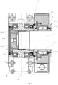
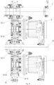
Figs. 10 to 11 show schematic assembly diagrams of the handrail belt spindle, the fifth driving motor, the sixth driving motor and the third gear box of the driving device according to the present disclosure. - The following is a detailed explanation of the specific implementation according to the disclosed content, combined with various drawings.
-
Figure 1 shows a three-dimensional schematic diagram of a driving device for an escalator according to an embodiment of the present disclosure, wherein the driving device comprises afirst driving motor 1, asecond driving motor 2, athird driving motor 3, afourth driving motor 4, a drivingspindle 7, and ahandrail belt spindle 8. Thefirst driving motor 1 and thesecond driving motor 2 are connected to afirst gearbox 10 through their respective planetary gear trains (not shown). The third driving motor and the fourth driving motor are connected to asecond gearbox 11 through their respective planetary gear trains. - Technicians in this field can understand that each planetary gear train can also be set in corresponding gearboxes.
- The driving torques of the first and
second driving motors spindle 7 through thefirst gear box 10, and the driving torques of the third andfourth driving motors spindle 7 through thesecond gear box 11. - The
first gear box 10 and thesecond gear box 11 each include a respective input gear, an intermediate transmission gear (not shown) and an output gear. Thefirst driving motor 1 and thesecond driving motor 2 are engaged with the corresponding input gears of thefirst gear box 10 and the second gear box through their respective planetary gear trains, and the driving torque is transmitted to the corresponding output gears through the corresponding intermediate transmission gears, and then to the drivingspindle 7. - As shown in
figs. 1 and2 , the driving device further includes afifth driving motor 5 and asixth driving motor 6. - The
fifth driving motor 5 and thesixth driving motor 6 are connected with thethird gear box 12 through respective planetary gear trains. - The driving torques of the
fifth driving motor 5 and thesixth driving motor 6 are transmitted to the drivingspindle 7 and thehandrail belt spindle 8 through thethird gear box 12. - The
fifth driving motor 5 is arranged between the drivingspindle 7 and thehandrail belt spindle 8. - The
handrail belt spindle 8 is arranged between thefifth driving motor 5 and thesixth driving motor 6. - The
third gear box 12 is disposed between thefirst gear box 10 and thesecond gear box 11 and is disposed closer to thefirst gear box 10 than thesecond gear box 11. - The driving
spindle 7 and thehandrail spindle 8 are arranged in parallel with each other. - According to the above embodiment of the present disclosure, in the direction parallel to the axis of the
handrail belt spindle 8, thefifth driving motor 5 and thesixth driving motor 6 are both located between thehandrail belt assemblies 9 provided at both axial ends of thehandrail belt spindle 8. -
Fig. 1 also shows six braking devices acting on the first to sixth driving motors respectively. - According to the above embodiments of the present disclosure, as shown in
figs. 3 and4 , a spline structure is provided on the outer circumferential surface of a first axial end 7-1 of the drivingspindle 7. - The output gear 10-1 of the
first gear box 10 has an output gear through hole 10-2, and a spline structure is provided on the inner circumferential surface of the output gear through hole 10-2. - The first axial end 7-1 of the driving
spindle 7 is fitted into the output gear through hole 10-2 of the output gear 10-1 of thefirst gear box 10, and the spline structure of the first axial end 7-1 of the drivingspindle 7 is fitted with the spline structure of the output gear through hole 10-2. - According to the above-mentioned embodiments of the present disclosure, as shown in
fig. 4 , a first axial protrusion 7-2 extends outward from the first axial end 7-1 of the drivingspindle 7. - A first axial end cap 7-3 is fixedly fitted on the first axial protrusion 7-2 by fasteners and abuts against the output gear 10-1 of the
first gear box 10. - According to the above embodiments of the present disclosure, as shown in
fig. 4 , a first annular recess 7-4 is provided on the drivingspindle 7 adjacent to the first axial end 7-1 of the drivingspindle 7. - A first cylindrical section 7-5 is provided on the driving
spindle 7 adjacent to the first annular recess 7-4 of the drivingspindle 7. - On the outer circumferential surface of the first cylindrical section 7-5, a first ferrule 7-6 is provided, which is located between the axial extension of the output gear 10-1 of the
first gear box 10 and the outer circumferential surface of the first cylindrical section 7-5. - The output gear 10-1 is supported by the driving
spindle 7 at its two ends along the axial direction of the driving spindle 7 (for example, one end is supported by the first ferrule 7-6 and the other end is supported by the first axial end cap 7-3 provided on the driving spindle 7), so that the spline structure of the first axial end 7-1 of the drivingspindle 7 does not bear radial pressure, but only bears driving torque. - A first double-
row roller bearing 13 is provided on the first cylindrical section 7-5. - A first spacer 7-7 is provided between an inner ring 13-1 of the first double-
row roller bearing 13 and the extended portion of the output gear 10-1 of thefirst gear box 10. - The extended portion of the output gear 10-1 of the
first gear box 10 abuts against the inner ring 13-1 of the first double-row roller bearing 13 through the first spacer 7-7. - According to the above embodiments of the present disclosure, as shown in
fig. 5 , a second cylindrical section 7-8 is provided on the drivingspindle 7 adjacent to the first cylindrical section 7-5 of the drivingspindle 7. - A first
step sprocket assembly 14 is fitted on the second cylindrical section 7-8. - The first
step sprocket assembly 14 includes a step flange 14-1 and a step sprocket 14-2, wherein the step sprocket 14-2 is connected to the step flange 14-1 through fasteners and cooperates with thesteps 15 of the escalator. - The step flange 14-1 has a step flange through hole 14-3.
- The step flange 14-1 is matched with the spline structure provided on the outer circumferential surface of the second cylindrical section 7-8 through the spline structure provided on the inner circumferential surface of the step flange through hole 14-3.
- According to the above embodiments of the present disclosure, as shown in
figs. 4 and5 , a second ferrule 7-9 is also provided on the outer circumferential surface of the first cylindrical section 7-5, and the second ferrule 7-9 is located between the step flange 14-1 and the outer circumferential surface of the first cylindrical section 7-5. - A second spacer 7-10 is provided between the inner ring 13-1 of the first double-
row roller bearing 13 and the stepped flange 14-1. - The inner ring 13-1 of the first double-
row roller bearing 13 abuts against the step flange 14-1 through the second spacer 7-10. - According to the above embodiments of the present disclosure, as shown in
fig. 5 , a third cylindrical section 7-11 is provided on the drivingspindle 7 adjacent to the second cylindrical section 7-8 of the drivingspindle 7. - An annular third spacer 7-12 is provided on an outer circumferential surface of the third cylindrical section 7-11.
- Two single-
row rolling bearings 16 are respectively provided on the outer circumferential surfaces of the two axial ends of the third spacers 7-12. - A first steering
plate mounting portion 17 is provided on the outer ring 16-1 of the two single-row rolling bearings 16. - A
first steering plate 18 is mounted on the first steeringplate mounting portion 17 through convex-concave fit, and one of the step wheels (not shown) of thesteps 15 of the escalator is rolling fitted on thefirst steering plate 18. - The stepped flange 14-1 abuts against the inner ring 16-2 of one of the single-
row rolling bearings 16 and abuts against the third spacer 7-12. - A first stopper 7-13 is connected to the first steering
plate mounting portion 17 by fasteners and extends to the rolling body of another single-row rolling bearing 16 along the radial direction of the third cylindrical section 7-11, thereby blocking the outer ring 16-1 of the other single-row rolling bearing 16 in the axial direction. - The stepped flange 14-1 is supported by the driving
spindle 7 at its two ends along the axial direction of the driving spindle 7 (for example, one end is supported by the second ferrule 7-9 and the other end is supported by the outer circumferential surface of the third cylindrical section 7-11), so that the spline structure provided on the outer circumferential surface of the second cylindrical section 7-8 does not bear radial pressure, but only bears driving torque. - According to the above embodiments of the present disclosure, as shown in
fig. 5 , the first steeringplate mounting portion 17 is provided with a first mounting portion boss 17-1. - The third spacer 7-12 is provided with a spacer boss 7-12-1 facing the first mounting boss 17-1.
- The outer rings 16-1 of the two single-
row rolling bearings 16 respectively abut against two axial ends of the first mounting boss 17-1. - The inner rings 16-2 of the two single-
row rolling bearings 16 abut against two axial ends of the spacer boss 7-12-1, respectively. - According to the above embodiments of the present disclosure, as shown in
fig. 6 , a fourth cylindrical section 7-14 and a fifth cylindrical section 7-15 are sequentially provided on the drivingspindle 7 adjacent to the third cylindrical section 7-11 of the drivingspindle 7. - On the outer circumferential surface of the fourth cylindrical section 7-14, a ring-shaped fourth spacer 7-16 is provided.
- As shown in
fig. 5 , the first axial end of the fourth spacer 7-16 is fitted on the third cylindrical section 7-11. - A second axial end of the fourth spacer 7-16 is fitted on the fifth cylindrical section 7-15.
- According to the above embodiments of the present disclosure, as shown in
figs. 5 and6 , the inner ring 16-2 of the other single-row rolling bearing 16 and the third spacer 7-12 abut on the first axial end of the fourth spacer 7-16. - The output gear 12-1 of the
third gear box 12 abuts against a step portion 7-16-1 provided on the second axial end of the fourth spacer 7-16. - A
first closing member 19 is also provided on the outer surface of the fourth spacer 7-16. - The
first closing member 19 is fixedly connected to a first side 12-3 of the housing 12-2 of thethird gear box 12 by fasteners. - According to the above embodiments of the present disclosure, as shown in
fig. 6 , a sixth cylindrical section 7-17 is provided on the drivingspindle 7 adjacent to the fifth cylindrical section 7-15 of the drivingspindle 7. - A spline structure is provided on an outer circumferential surface of the sixth cylindrical section 7-17.
- The output gear 12-1 of the
third gear box 12 has an output gear through hole 12-4, and a spline structure is provided on the inner circumferential surface of the output gear through hole 12-4 of the output gear 12-1 of thethird gear box 12. - The sixth cylindrical section 7-17 of the driving
spindle 7 is splined in the output gear through hole 12-4 of the output gear 12-1 of thethird gear box 12. - According to the above embodiments of the present disclosure, as shown in
fig. 6 , a second annular recess 7-18 is provided on the drivingspindle 7 adjacent to the sixth cylindrical section 7-17 of the drivingspindle 7. - A seventh cylindrical section 7-19 and an eighth cylindrical section 7-20 are sequentially arranged on the driving
spindle 7 adjacent to the second annular recess 7-18 of the drivingspindle 7. - The output gear 12-1 of the
third gear box 12 is fitted on the seventh cylindrical section 7-19 and abuts against a step portion 7-21 formed between the seventh cylindrical section 7-19 and the eighth cylindrical section 7-20. - A
second closing member 20 is also provided on the outer surface of the eighth cylindrical section 7-20. - The
second closing member 20 is fixedly connected to a second side 12-5 of the housing 12-2 of thethird gear box 12 by fasteners. - The output gear 12-1 is supported by the driving
spindle 7 at its two ends in the axial direction of the driving spindle 7 (for example, one end is supported by the seventh cylindrical section 7-19 and the other end is supported by the step portion 7-16-1 of the fourth spacer 7-16), so that the spline structure provided on the outer circumferential surface of the sixth cylindrical section 7-17 does not bear radial pressure, but only bears driving torque. - According to the above embodiments of the present disclosure, as shown in
fig. 8 , a spline structure is provided on the outer circumferential surface of the second axial end 7-22 of the drivingspindle 7. - The output gear 11-1 of the
second gear box 11 has an output gear through hole 11-2, and a spline structure is provided on the inner circumferential surface of the output gear through hole 11-2. - The second axial end 7-22 of the driving
spindle 7 is fitted in the output gear through hole 11-2 of the output gear 11-1 of thesecond gearbox 11, and the spline structure of the second axial end 7-22 of the drivingspindle 7 is fitted with the spline structure of the output gear through hole 11-2. - According to the above-mentioned embodiments of the present disclosure, as shown in
fig. 8 , a second axial protrusion 7-23 extends outwardly from the second axial end 7-22 of the drivingspindle 7. - A second axial end caps 7-24 are fixedly fitted on the second axial protrusions 7-23 by fasteners and abut against the output gear 11-1 of the
second gear box 11. - According to the above embodiments of the present disclosure, as shown in
fig. 8 , a third annular recess 7-25 is provided on the drivingspindle 7 adjacent to the second axial end 7-22 of the drivingspindle 7. - A ninth cylindrical section 7-26 is provided on the driving
spindle 7 adjacent to the third annular recess 7-25 of the drivingspindle 7. - On the outer circumferential surface of the ninth cylindrical section 7-26, a third ferrule 7-27 is provided, which is located between an extended portion of the output gear 11-1 of the
second gearbox 11 and the outer circumferential surface of the ninth cylindrical section 7-26. - A second double-
row roller bearing 21 is arranged on the ninth cylindrical section 7-26. - A fifth spacer 7-28 is provided between the inner ring 21-1 of the second double-
row roller bearing 21 and the extended portion of the output gear 11-1 of thesecond gear box 11. - The extended portion of the output gear 11-1 of the
second gear box 11 abuts against the inner ring 21-1 of the second double-row roller bearing 21 through the fifth spacer 7-28. - The output gear 11-1 is supported by the driving
spindle 7 at its two ends along the axial direction of the driving spindle 7 (for example, one end is supported by the third ferrule 7-27 and the other end is supported by the second axial end cap 7-24 provided on the driving spindle 7), so that the spline structure of the second axial end 7-22 of the drivingspindle 7 is not subjected to radial pressure, but only to driving torque. - According to the above embodiments of the present disclosure, as shown in
fig. 7 , a tenth cylindrical section 7-29 is provided on the drivingspindle 7 adjacent to the ninth cylindrical section 7-26 of the drivingspindle 7. - A second
step sprocket assembly 22 is fitted on the tenth cylindrical section 7-29. - The second
step sprocket assembly 22 includes a step flange 22-1 and a step sprocket 22-2, wherein the step sprocket 22-2 is connected to the step flange 22-1 through fasteners and cooperates with thesteps 15 of the escalator. - The step flange 22-1 has a step flange through hole 22-3.
- The step flange 22-1 is matched with the spline structure provided on an outer circumferential surface of the tenth cylindrical section 7-29 through the spline structure provided on an inner circumferential surface of the step flange through hole 22-3.
- According to the above embodiments of the present disclosure, as shown in
figs. 7 and8 , a fourth ferrule 7-30 is further provided on the outer circumferential surface of the ninth cylindrical section 7-26, and the fourth ferrule 7-30 is located between the step flange 22-1 and the outer circumferential surface of the ninth cylindrical section 7-26. - A sixth spacer 7-31 is provided between the inner ring 21-1 of the second double-
row roller bearing 21 and the step flange 22-1 of the secondstep sprocket assembly 22. - The inner ring 21-1 of the second double-
row roller bearing 21 abuts against the step flange 22-1 of the secondstep sprocket assembly 22 and against the fourth ferrule 7-30 through the sixth spacer 7-31. - According to the above embodiments of the present disclosure, as shown in
fig. 7 , an eleventh cylindrical section 7-32 are provided on the drivingspindle 7 adjacent to the tenth cylindrical section 7-29 of the drivingspindle 7. - An annular seventh spacer 7-33 is provided on the outer circumferential surface of the eleventh cylindrical section 7-32.
- A single-
row rolling bearing 16 is provided on the outer circumferential surface of the two axial ends of the seventh spacers 7-33, respectively. - A second steering
plate mounting portion 23 is provided on the outer ring 16-1 of the two single-row rolling bearings 16. - A
second steering plate 24 is mounted on the second steeringplate mounting portion 23 through convex-concave fit, and another step wheel (not shown) of theescalator step 15 is rolled and fitted on thesecond steering plate 24. - The step flange 22-1 of the second
step sprocket assembly 22 abuts against the inner ring 16-2 of one of the singlerow rolling bearings 16 and abuts against the seventh spacer 7-33. - The stepped flange 22-1 is supported by the driving
spindle 7 at its two ends in the axial direction of the driving spindle 7 (for example, one end is supported by the fourth ferrule 7-30 and the other end is supported by the outer circumferential surface of a part of the tenth cylindrical section 7-29), so that the spline structure provided on the outer circumferential surface of the tenth cylindrical section 7-29 does not bear radial pressure, but only bears driving torque. - As shown in
fig. 7 , a second stopper 7-34 is connected to the second steeringplate mounting portion 23 by fasteners and extends to the rolling body of another single-row rolling bearing 16 along the radial direction of the eleventh cylindrical section 7-32, thereby blocking the outer ring 16-1 of the other single-row rolling bearing 16 in the axial direction. - The second steering
plate mounting portion 23 is provided with a second mounting portion boss 23-1. - The seventh spacer 7-33 is provided with a spacer boss 7-33-1 facing the second mounting boss 23-1.
- The outer ring 16-1 of the two single-
row rolling bearings 16 respectively abuts against the two axial ends of the second mounting boss 23-1. - The inner ring 16-2 of the two single-
row rolling bearings 16 abuts against the two axial ends of the spacer bosses 7-33-1, respectively. - According to the above embodiments of the present disclosure, as shown in
fig. 7 , the seventh spacer 7-33 abuts against a step portion 7-35 formed between the eleventh cylindrical section 7-32 and the eighth cylindrical section 7-20. - According to the above-mentioned embodiments of the present disclosure, as shown in
figs. 9 to 10 , thethird gear box 12 includes an output gear 12-1, a first input gear 12-6, a handrail belt spindle gear 12-7 and a second input gear 12-8 arranged in its housing. - The
fifth driving motor 5 drives the first input gear 12-6 through its gear transmission mechanism such as a planetary gear train (not shown). - The
sixth driving motor 6 drives the second input gear 12-8 through its gear transmission mechanism such as a planetary gear train (not shown). - The first input gear 12-6 is simultaneously matched with the output gear 12-1 and the handrail belt spindle gear 12-7.
- The second input gear 12-8 is engaged with the handrail belt spindle gear 12-7.
- The driving torque of the
fifth driving motor 5 is transmitted to the drivingspindle 7 through the input gear 12-1 and to thehandrail belt spindle 8 through the handrail belt spindle gear 12-7. - The driving torque of the
sixth driving motor 6 is transmitted to thehandrail belt spindle 8 through the handrail belt spindle gear 12-7. - According to the above embodiments of the present disclosure, as shown in
fig. 11 , a spline structure is provided on the outer circumferential surface of a part 8-1 of thehandrail spindle 8. - The handrail belt spindle gear 12-7 has a handrail belt gear through hole 12-7-1, and a spline structure is arranged on the inner circumferential surface of the handrail belt gear through hole 12-7-1.
- The handrail
main shaft 8 is fitted in the handrail belt gear through hole 12-7-1, and the spline structure on the inner circumferential surface of the handrail belt gear through hole 12-7-1 is fitted with the spline structure on the outer circumferential surface of the part of thehandrail belt spindle 8. - According to the above embodiments of the present disclosure, as shown in
fig. 9 , twohandrail assemblies 9 are provided on both axial ends of thehandrail belt spindle 8 respectively. - The rotation of the
handrail belt spindle 8 drives thehandrail assemblies 9 to move. - According to the above-mentioned embodiments of the present disclosure, as shown in
fig. 11 , athird closing member 25 and afourth closing member 26 are further provided on thehandrail belt spindle 8. - The
third closing member 25 and thefourth closing member 26 are fixedly connected to both sides of the housing 12-2 of thethird gear box 12 through fasteners. - As shown in
fig. 11 , the housing 12-2 of thethird gear box 12 is provided with a third gear box opening 12-9. A handrail belt spindle gear axial extension 12-7-2 of the handrail belt spindle gear 12-7 is arranged in the third gear box opening 12-9 and extends out of the housing 12-2 of thethird gear box 12 from the third gear box opening 12-9. - The handrail belt spindle gear axial extension 12-7-2 is supported by the
handrail belt spindle 8 at its two ends along the axial direction of the handrail belt spindle 8 (for example, one end is supported by thehandrail belt spindle 8 and the other end is supported by the handrail belt spindle collar provided on the handrail spindle 8), so that the spline structure on the outer circumferential surface of the part of thehandrail belt spindle 8 does not bear radial pressure, but only bears driving torque. - A
radial spacer 27 is provided in the third gear box opening 12-9. Theradial spacer 27 is located between the handrail belt spindle gear axial extension 12-7-2 and an inner circumferential surface of the third gear box opening 12-9 in the radial direction of the third gear box opening 12-0. - The
radial spacer 27 abuts against a step formed on the handrail belt spindle gear axial extension 12-7-2 at one side thereof. Thethird closing member 25 and thefourth closing member 26 abut against the other side of theradial spacer 27 through a stopper. - The foregoing disclosure provides illustration and description, but is not intended to be exhaustive or to limit the embodiments to the precise forms disclosed. Modifications and variations are possible in light of the above disclosure, or may be acquired from practice of the embodiments.
- Even if specific combinations of features are recited in the claims and/or disclosed in the specification, these combinations are not intended to limit the disclosure of various embodiments. In fact, many of these features can be combined in ways not specifically recited in the claims and/or not specifically disclosed in the specification. Although each dependent claim listed below may directly depend on only one claim, the disclosure of various embodiments includes each dependent claim in combination with every other claim in the claim set.
Claims (16)
- A driving device for escalators, comprising a first driving motor, a second driving motor, a third driving motor, a fourth driving motor, a driving spindle and a handrail belt spindle, wherein the first driving motor and the second driving motor are connected with a first gear box, and the third driving motor and the fourth driving motor are connected with a second gear box, the driving torque of the first driving motor and the second driving motor is transmitted to the driving spindle through the first gear box, and the driving torque of the third driving motor and the fourth driving motor are transmitted to the driving spindle through the second gear box;wherein the driving device further comprises at least one fifth driving motor and at least one sixth driving motor;the fifth driving motor and the sixth driving motor are connected with at least one third gear box;the driving torque of the fifth driving motor and the sixth driving motor is transmitted to the driving spindle and the handrail belt spindle through the third gear box.
- The driving device according to claim 1, wherein,the fifth driving motor is arranged between the driving spindle and the handrail belt spindle;the handrail belt spindle is arranged between the fifth driving motor and the sixth driving motor;the third gear box is disposed between the first gear box and the second gear box and is disposed closer to the first gear box than the second gear box; and wherein,in a direction parallel to an axis of the handrail belt spindle, the fifth driving motor and the sixth driving motor are both located between the handrail belt assemblies arranged on two axial ends of the handrail belt spindle; and wherein,the first driving motor and the second driving motor are connected with the first gear box through a gear transmission mechanism;the third driving motor and the fourth driving motor are connected with the second gear box through a gear transmission mechanism;the fifth driving motor and the sixth driving motor are connected with said at least one third gear box through a gear transmission mechanism.
- The driving device according to claim 2, wherein,the third gear box comprises an output gear, a first input gear, a handrail belt spindle gear and a second input gear which are arranged in a housing of the third gear box;the fifth driving motor drives the first input gear;the sixth driving motor drives the second input gear;the first input gear is matched with the output gear and the handrail belt spindle gear at the same time;the second input gear is matched with the handrail belt spindle gear;the driving torque of the fifth driving motor is transmitted to the driving spindle through the input gear and to the handrail belt spindle through the handrail belt spindle gear;the driving torque of the sixth driving motor is transmitted to the handrail belt spindle through the handrail belt spindle gear.
- The driving device according to claim 3, wherein,a spline structure is arranged on the outer circumferential surface of a part of handrail belt spindle;the handrail belt spindle gear is provided with a handrail gear through hole, and a spline structure is arranged on the inner circumferential surface of the handrail gear through hole;the handrail belt spindle is fitted in the handrail gear through hole, and the spline structure on the inner circumferential surface of the handrail gear through hole is fitted with the spline structure on the outer circumferential surface of the part of the handrail belt spindle, andwherein,the handrail belt assembly are arranged on two axial ends of the handrail belt spindle;the rotation of the handrail belt spindle drives the handrail belt assembly to move.
- The driving device according to claim 4, wherein,the handrail belt spindle is also provided with a third sealing piece and a fourth sealing piece;the third sealing piece and the fourth sealing piece are respectively and fixedly connected to two sides of the housing of the third gear box through fasteners.
- The driving device according to claim 5, wherein,a spline structure is arranged on the outer circumferential surface of the first axial end of the driving spindle;the output gear of the first gear box is provided with an output gear through hole, and the inner circumferential surface of the output gear through hole is provided with a spline structure;the first axial end of the driving spindle is fitted in the output gear through hole of the output gear of the first gearbox, and the spline structure of the first axial end of the driving spindle is fitted with the spline structure of the output gear through hole.
- The driving device according to claim 6, wherein,a first axial protrusion extending outward from the first axial end of the driving spindle;a first axial end cap is fixedly fitted on the first axial protrusion through a fastener and abuts against the output gear of the first gear box, andwherein,a first annular recess is arranged on the driving spindle adjacent to the first axial end of the driving spindle;a first cylindrical section is arranged on the driving spindle adjacent to the first annular recess of the driving spindle;a first ferrule is arranged on the outer circumferential surface of the first cylindrical section, and the first ferrule is located between an extended part of the output gear of the first gearbox and the outer circumferential surface of the first cylindrical section;a first double-row roller bearing is arranged on the first cylindrical section;a first spacer is arranged between an inner ring of the first double-row roller bearing and the extended part of the output gear of the first gear box;the extended part of the output gear of the first gear box abuts against the inner ring of the first double-row roller bearing through the first spacer.
- The driving device according to claim 7, wherein,a second cylindrical section is arranged on the driving spindle adjacent to the first cylindrical section of the driving spindle;a first step sprocket assembly is fitted on the second cylindrical section;the first step sprocket assembly comprises a step flange and a step sprocket, wherein the step sprocket is connected to the step flange through a fastener and is matched with the steps of the escalator;the step flange is provided with a step flange through hole;the step flange is matched with the spline structure arranged on the outer circumferential surface of the second cylindrical section through the spline structure arranged on the inner circumferential surface of the step flange through hole.
- The driving device according to claim 8, wherein,a second ferrule is arranged on the outer circumferential surface of the first cylindrical section, and the second ferrule is located between the step flange and the outer circumferential surface of the first cylindrical section;a second spacer is arranged between the inner ring of the first double-row roller bearing and the step flange;the inner ring of the first double-row roller bearing abuts against the step flange through the second spacer.
- The driving device according to claim 9, wherein,a third cylindrical section is arranged on the driving spindle adjacent to the second cylindrical section of the driving spindle;a ring-shaped third spacer is arranged on the outer circumferential surface of the third cylindrical section;two single-row rolling bearings are respectively arranged on the outer circumferential surfaces of the two axial ends of the third spacer;a first steering plate mounting part is arranged on the outer rings of the two single-row rolling bearings;a first steering plate is installed on the first steering plate mounting part through convex-concave fit, and one of the step runner of the escalator is rolling fitted on the first steering plate;the stepped flange abuts against the inner ring of one of the single-row rolling bearings and abuts against the third spacer;a first stopper is connected to the first steering plate mounting part through a fastener and extends to the rolling body of another single-row rolling bearing along the radial direction of the third cylindrical section, thereby blocking the outer ring of the other single-row rolling bearing in the axial direction;a first mounting part boss is arranged on the first steering plate mounting part; a spacer boss facing the first mounting part boss is arranged on the third spacer; the outer rings of the two single-row rolling bearings respectively abut against the two axial ends of the first mounting part boss;the inner rings of the two single-row rolling bearings respectively abut against the two axial ends of the spacer boss.
- The driving device according to claim 10, wherein,a fourth cylindrical section and a fifth cylindrical section are sequentially arranged on the driving spindle adjacent to the third cylindrical section of the driving spindle;a fourth spacer in the shape of a ring is arranged on an outer circumferential surface of the fourth cylindrical section;a first axial end of the fourth spacer is fitted on the third cylindrical section;a second axial end of the fourth spacer is fitted on the fifth cylindrical section, andwherein,the inner ring of the other single-row rolling bearing and the third spacer abut against the first axial end of the fourth spacer;the output gear of the third gear box abuts against a step portion provided on the second axial end of the fourth spacer;a first closing part is also arranged on the outer surface of the fourth spacer; the first closing member is fixedly connected to the first side of the housing of the third gear box by fastener, andwherein,a sixth cylindrical section is arranged on the driving spindle adjacent to the fifth cylindrical section of the driving spindle;a spline structure is arranged on the outer circumferential surface of the sixth cylindrical section;the output gear of the third gearbox is provided with an output gear through hole, and the inner circumferential surface of the output gear through hole of the output gear of the third gearbox is provided with a spline structure;the sixth cylindrical section of the driving spindle is splined in the output gear through hole of the output gear of the third gearbox.
- The driving device according to claim 11, wherein,a second annular recess is arranged on the driving spindle adjacent to the sixth cylindrical section of the driving spindle;a seventh cylindrical section and an eighth cylindrical section are sequentially arranged on the driving spindle adjacent to the second annular recess of the driving spindle;the output gear of the third gear box is fitted on the seventh cylindrical section and abuts against a step portion formed between the seventh cylindrical section and the eighth cylindrical section;a second closing part is also arranged on the outer surface of the eighth cylindrical section;the second closing member is fixedly connected to the second side of the housing of the third gear box by fastener.
- The driving device according to claim 12, wherein,a spline structure is arranged on the outer circumferential surface of the second axial end of the driving spindle;the output gear of the second gearbox is provided with an output gear through hole, and the inner circumferential surface of the output gear through hole is provided with a spline structure;the second axial end of the driving spindle is fitted in the output gear through hole of the output gear of the second gearbox, and the spline structure of the second axial end of the driving spindle is fitted with the spline structure of the output gear through hole, andwherein,a second axial protrusion extending outward from the second axial end of the driving spindle;a second axial end cap is fixedly fitted on the second axial protrusion through a fastener and abuts against the output gear of the second gearbox.
- The driving device according to claim 13, wherein,a third annular recess is arranged on the driving spindle adjacent to the second axial end of the driving spindle;a ninth cylindrical section is arranged on the driving spindle adjacent to the third annular recess of the driving spindle;a third collar is arranged on the outer circumferential surface of the ninth cylindrical section, and the third collar is located between an extended part of the output gear of the second gearbox and the outer circumferential surface of the ninth cylindrical section;a second double-row roller bearing is arranged on the ninth cylindrical section; a fifth spacer is arranged between the inner ring of the second double-row roller bearing and the extended part of the output gear of the second gearbox;the extended part of the output gear of the second gear box abuts against the inner ring of the second double-row roller bearing through the fifth spacer.
- The driving device according to claim 14, wherein,a tenth cylindrical section is arranged on the driving spindle adjacent to the ninth cylindrical section of the driving spindle;a second step sprocket assembly is fitted on the tenth cylindrical section;the second step sprocket assembly comprises a step flange and a step sprocket, wherein the step sprocket is connected to the step flange through a fastener and is matched with the steps of the escalator;the step flange is provided with a step flange through hole;the step flange is matched with the spline structure arranged on the outer circumferential surface of the tenth cylindrical section through the spline structure arranged on the inner circumferential surface of the step flange through hole, andwherein,a fourth collar is also arranged on the outer circumferential surface of the ninth cylindrical section, and the fourth collar is located between the step flange and the outer circumferential surface of the ninth cylindrical section;a sixth spacer is arranged between the inner ring of the second double-row roller bearing and the step flange of the second step sprocket assembly;the inner ring of the second double-row roller bearing abuts against the step flange of the second step sprocket assembly through the sixth spacer.
- The driving device according to claim 15, wherein,an eleventh cylindrical section is arranged on the driving spindle adjacent to the tenth cylindrical section of the driving spindle;an annular seventh spacer is arranged on the outer circumferential surface of the eleventh cylindrical section;two single-row rolling bearings are respectively arranged on the outer circumferential surfaces of the two axial ends of the seventh spacer;a second steering plate mounting part is arranged on the outer rings of the two single-row rolling bearings;a second steering plate is installed on the second steering plate mounting part through convex-concave fit, and another step runner of the escalator steps is rolled and matched on the second steering plate;the stepped flange abuts against the inner ring of one of the single-row rolling bearings and abuts against the seventh spacer;a second stopper is connected to the second steering plate mounting part through a fastener and extends to the rolling body of another single-row rolling bearing along the radial direction of the eleventh cylindrical section, thereby blocking the outer ring of the other single-row rolling bearing in the axial direction;a second mounting part boss is arranged on the second steering plate mounting part;a spacer boss facing the second mounting part boss is arranged on the seventh spacer;the outer rings of the two single-row rolling bearings respectively abut against the two axial ends of the second mounting part boss ;the inner rings of the two single-row rolling bearings respectively abut against the two axial ends of the spacer boss, andwherein,the seventh spacer abuts against a step portion formed between the eleventh cylindrical section of the driving spindle and the eighth cylindrical section of the driving spindle.
Applications Claiming Priority (1)
| Application Number | Priority Date | Filing Date | Title |
|---|---|---|---|
| CN202211101033.6A CN117699618A (en) | 2022-09-09 | 2022-09-09 | Driving device of escalator |
Publications (2)
| Publication Number | Publication Date |
|---|---|
| EP4335804A1 true EP4335804A1 (en) | 2024-03-13 |
| EP4335804B1 EP4335804B1 (en) | 2025-07-09 |
Family
ID=87930309
Family Applications (1)
| Application Number | Title | Priority Date | Filing Date |
|---|---|---|---|
| EP23195014.8A Active EP4335804B1 (en) | 2022-09-09 | 2023-09-04 | A driving device for an escalator |
Country Status (3)
| Country | Link |
|---|---|
| EP (1) | EP4335804B1 (en) |
| CN (1) | CN117699618A (en) |
| FI (1) | FI4335804T3 (en) |
Citations (3)
| Publication number | Priority date | Publication date | Assignee | Title |
|---|---|---|---|---|
| GB1445555A (en) * | 1974-05-04 | 1976-08-11 | Orenstein & Koppel Ag | Driving means for escalators and other moving pathways |
| JP2000177964A (en) * | 1998-12-14 | 2000-06-27 | Hitachi Ltd | Passenger conveyor |
| JP4473359B2 (en) * | 1998-02-13 | 2010-06-02 | インベンテイオ・アクテイエンゲゼルシヤフト | Escalator drive |
-
2022
- 2022-09-09 CN CN202211101033.6A patent/CN117699618A/en active Pending
-
2023
- 2023-09-04 EP EP23195014.8A patent/EP4335804B1/en active Active
- 2023-09-04 FI FIEP23195014.8T patent/FI4335804T3/en active
Patent Citations (3)
| Publication number | Priority date | Publication date | Assignee | Title |
|---|---|---|---|---|
| GB1445555A (en) * | 1974-05-04 | 1976-08-11 | Orenstein & Koppel Ag | Driving means for escalators and other moving pathways |
| JP4473359B2 (en) * | 1998-02-13 | 2010-06-02 | インベンテイオ・アクテイエンゲゼルシヤフト | Escalator drive |
| JP2000177964A (en) * | 1998-12-14 | 2000-06-27 | Hitachi Ltd | Passenger conveyor |
Also Published As
| Publication number | Publication date |
|---|---|
| FI4335804T3 (en) | 2025-08-27 |
| FI4335804T1 (en) | 2025-06-30 |
| CN117699618A (en) | 2024-03-15 |
| EP4335804B1 (en) | 2025-07-09 |
Similar Documents
| Publication | Publication Date | Title |
|---|---|---|
| CN100540351C (en) | electric wheel driving device | |
| US7530416B2 (en) | Motor-driven wheel driving apparatus | |
| CN103718434B (en) | Driver element for the close wheel of automobile | |
| TWI425154B (en) | Concentric alignment planetary gear set and power transmission | |
| CN1829872A (en) | Planet carrier for a gearbox | |
| KR20190124721A (en) | Automotive multi-clutch unit and hybrid module | |
| CN105051393A (en) | Transmission device | |
| TW202045834A (en) | Clutch device | |
| CN102060080A (en) | Driving mechanism of retarding motor | |
| KR101810756B1 (en) | Power transmission device | |
| EP4335804B1 (en) | A driving device for an escalator | |
| CN109958741B (en) | Transmission for railway vehicle and railway vehicle | |
| JP6119379B2 (en) | Power transmission device | |
| CN219279219U (en) | Driving device of escalator | |
| CN202127332U (en) | Hub motor | |
| KR101332349B1 (en) | In-wheel Driving System for Motor Vehicle | |
| CN101087088A (en) | An electromotive wheel hub electromotor | |
| CN110154744A (en) | In-wheel motor drive | |
| JP2012225371A (en) | Hybrid vehicle drive device | |
| CN203627707U (en) | Executor with small tooth difference between worm wheel groups | |
| JP6581453B2 (en) | In-wheel motor drive device | |
| KR20140013316A (en) | Wheel bearing, constant velocity joint and jointing structure for wheel bearing and constant velocity joint | |
| JP2016070330A (en) | Power transmission device | |
| CN113727876A (en) | Hybrid module and drive for a motor vehicle | |
| NL2011954C2 (en) | Compact integrated motor-gear drive unit with cycloidal reduction. |
Legal Events
| Date | Code | Title | Description |
|---|---|---|---|
| PUAI | Public reference made under article 153(3) epc to a published international application that has entered the european phase |
Free format text: ORIGINAL CODE: 0009012 |
|
| STAA | Information on the status of an ep patent application or granted ep patent |
Free format text: STATUS: THE APPLICATION HAS BEEN PUBLISHED |
|
| AK | Designated contracting states |
Kind code of ref document: A1 Designated state(s): AL AT BE BG CH CY CZ DE DK EE ES FI FR GB GR HR HU IE IS IT LI LT LU LV MC ME MK MT NL NO PL PT RO RS SE SI SK SM TR |
|
| P01 | Opt-out of the competence of the unified patent court (upc) registered |
Effective date: 20240404 |
|
| STAA | Information on the status of an ep patent application or granted ep patent |
Free format text: STATUS: REQUEST FOR EXAMINATION WAS MADE |
|
| 17P | Request for examination filed |
Effective date: 20240820 |
|
| RBV | Designated contracting states (corrected) |
Designated state(s): AL AT BE BG CH CY CZ DE DK EE ES FI FR GB GR HR HU IE IS IT LI LT LU LV MC ME MK MT NL NO PL PT RO RS SE SI SK SM TR |
|
| GRAP | Despatch of communication of intention to grant a patent |
Free format text: ORIGINAL CODE: EPIDOSNIGR1 |
|
| STAA | Information on the status of an ep patent application or granted ep patent |
Free format text: STATUS: GRANT OF PATENT IS INTENDED |
|
| INTG | Intention to grant announced |
Effective date: 20250319 |
|
| GRAS | Grant fee paid |
Free format text: ORIGINAL CODE: EPIDOSNIGR3 |
|
| GRAA | (expected) grant |
Free format text: ORIGINAL CODE: 0009210 |
|
| STAA | Information on the status of an ep patent application or granted ep patent |
Free format text: STATUS: THE PATENT HAS BEEN GRANTED |
|
| AK | Designated contracting states |
Kind code of ref document: B1 Designated state(s): AL AT BE BG CH CY CZ DE DK EE ES FI FR GB GR HR HU IE IS IT LI LT LU LV MC ME MK MT NL NO PL PT RO RS SE SI SK SM TR |
|
| REG | Reference to a national code |
Ref country code: GB Ref legal event code: FG4D |
|
| REG | Reference to a national code |
Ref country code: CH Ref legal event code: EP |
|
| REG | Reference to a national code |
Ref country code: IE Ref legal event code: FG4D |
|
| REG | Reference to a national code |
Ref country code: DE Ref legal event code: R096 Ref document number: 602023004668 Country of ref document: DE |
|
| REG | Reference to a national code |
Ref country code: FI Ref legal event code: FGE |
|
| REG | Reference to a national code |
Ref country code: SE Ref legal event code: TRGR |
|
| PGFP | Annual fee paid to national office [announced via postgrant information from national office to epo] |
Ref country code: FI Payment date: 20250926 Year of fee payment: 3 |
|
| PGFP | Annual fee paid to national office [announced via postgrant information from national office to epo] |
Ref country code: DE Payment date: 20250919 Year of fee payment: 3 |
|
| PGFP | Annual fee paid to national office [announced via postgrant information from national office to epo] |
Ref country code: AT Payment date: 20251020 Year of fee payment: 3 |
|
| PGFP | Annual fee paid to national office [announced via postgrant information from national office to epo] |
Ref country code: SE Payment date: 20250918 Year of fee payment: 3 |
|
| REG | Reference to a national code |
Ref country code: NL Ref legal event code: MP Effective date: 20250709 |
|
| PG25 | Lapsed in a contracting state [announced via postgrant information from national office to epo] |
Ref country code: PT Free format text: LAPSE BECAUSE OF FAILURE TO SUBMIT A TRANSLATION OF THE DESCRIPTION OR TO PAY THE FEE WITHIN THE PRESCRIBED TIME-LIMIT Effective date: 20251110 |
|
| PG25 | Lapsed in a contracting state [announced via postgrant information from national office to epo] |
Ref country code: NL Free format text: LAPSE BECAUSE OF FAILURE TO SUBMIT A TRANSLATION OF THE DESCRIPTION OR TO PAY THE FEE WITHIN THE PRESCRIBED TIME-LIMIT Effective date: 20250709 |
|
| REG | Reference to a national code |
Ref country code: AT Ref legal event code: MK05 Ref document number: 1811709 Country of ref document: AT Kind code of ref document: T Effective date: 20250709 |
|
| PG25 | Lapsed in a contracting state [announced via postgrant information from national office to epo] |
Ref country code: IS Free format text: LAPSE BECAUSE OF FAILURE TO SUBMIT A TRANSLATION OF THE DESCRIPTION OR TO PAY THE FEE WITHIN THE PRESCRIBED TIME-LIMIT Effective date: 20251109 |
|
| PG25 | Lapsed in a contracting state [announced via postgrant information from national office to epo] |
Ref country code: NO Free format text: LAPSE BECAUSE OF FAILURE TO SUBMIT A TRANSLATION OF THE DESCRIPTION OR TO PAY THE FEE WITHIN THE PRESCRIBED TIME-LIMIT Effective date: 20251009 |
|
| REG | Reference to a national code |
Ref country code: LT Ref legal event code: MG9D |
|
| PG25 | Lapsed in a contracting state [announced via postgrant information from national office to epo] |
Ref country code: AT Free format text: LAPSE BECAUSE OF FAILURE TO SUBMIT A TRANSLATION OF THE DESCRIPTION OR TO PAY THE FEE WITHIN THE PRESCRIBED TIME-LIMIT Effective date: 20250709 |
|
| PG25 | Lapsed in a contracting state [announced via postgrant information from national office to epo] |
Ref country code: HR Free format text: LAPSE BECAUSE OF FAILURE TO SUBMIT A TRANSLATION OF THE DESCRIPTION OR TO PAY THE FEE WITHIN THE PRESCRIBED TIME-LIMIT Effective date: 20250709 |
|
| PG25 | Lapsed in a contracting state [announced via postgrant information from national office to epo] |
Ref country code: GR Free format text: LAPSE BECAUSE OF FAILURE TO SUBMIT A TRANSLATION OF THE DESCRIPTION OR TO PAY THE FEE WITHIN THE PRESCRIBED TIME-LIMIT Effective date: 20251010 |
|
| PG25 | Lapsed in a contracting state [announced via postgrant information from national office to epo] |
Ref country code: LV Free format text: LAPSE BECAUSE OF FAILURE TO SUBMIT A TRANSLATION OF THE DESCRIPTION OR TO PAY THE FEE WITHIN THE PRESCRIBED TIME-LIMIT Effective date: 20250709 |
|
| PG25 | Lapsed in a contracting state [announced via postgrant information from national office to epo] |
Ref country code: BG Free format text: LAPSE BECAUSE OF FAILURE TO SUBMIT A TRANSLATION OF THE DESCRIPTION OR TO PAY THE FEE WITHIN THE PRESCRIBED TIME-LIMIT Effective date: 20250709 Ref country code: PL Free format text: LAPSE BECAUSE OF FAILURE TO SUBMIT A TRANSLATION OF THE DESCRIPTION OR TO PAY THE FEE WITHIN THE PRESCRIBED TIME-LIMIT Effective date: 20250709 |
|
| PG25 | Lapsed in a contracting state [announced via postgrant information from national office to epo] |
Ref country code: RS Free format text: LAPSE BECAUSE OF FAILURE TO SUBMIT A TRANSLATION OF THE DESCRIPTION OR TO PAY THE FEE WITHIN THE PRESCRIBED TIME-LIMIT Effective date: 20251009 |
|
| PG25 | Lapsed in a contracting state [announced via postgrant information from national office to epo] |
Ref country code: ES Free format text: LAPSE BECAUSE OF FAILURE TO SUBMIT A TRANSLATION OF THE DESCRIPTION OR TO PAY THE FEE WITHIN THE PRESCRIBED TIME-LIMIT Effective date: 20250709 |
|
| PG25 | Lapsed in a contracting state [announced via postgrant information from national office to epo] |
Ref country code: RO Free format text: LAPSE BECAUSE OF FAILURE TO SUBMIT A TRANSLATION OF THE DESCRIPTION OR TO PAY THE FEE WITHIN THE PRESCRIBED TIME-LIMIT Effective date: 20250709 |
|
| PG25 | Lapsed in a contracting state [announced via postgrant information from national office to epo] |
Ref country code: SM Free format text: LAPSE BECAUSE OF FAILURE TO SUBMIT A TRANSLATION OF THE DESCRIPTION OR TO PAY THE FEE WITHIN THE PRESCRIBED TIME-LIMIT Effective date: 20250709 |
|
| PG25 | Lapsed in a contracting state [announced via postgrant information from national office to epo] |
Ref country code: DK Free format text: LAPSE BECAUSE OF FAILURE TO SUBMIT A TRANSLATION OF THE DESCRIPTION OR TO PAY THE FEE WITHIN THE PRESCRIBED TIME-LIMIT Effective date: 20250709 |
|
| PG25 | Lapsed in a contracting state [announced via postgrant information from national office to epo] |
Ref country code: IT Free format text: LAPSE BECAUSE OF FAILURE TO SUBMIT A TRANSLATION OF THE DESCRIPTION OR TO PAY THE FEE WITHIN THE PRESCRIBED TIME-LIMIT Effective date: 20250709 |
|
| PG25 | Lapsed in a contracting state [announced via postgrant information from national office to epo] |
Ref country code: CZ Free format text: LAPSE BECAUSE OF FAILURE TO SUBMIT A TRANSLATION OF THE DESCRIPTION OR TO PAY THE FEE WITHIN THE PRESCRIBED TIME-LIMIT Effective date: 20250709 |
|
| PG25 | Lapsed in a contracting state [announced via postgrant information from national office to epo] |
Ref country code: EE Free format text: LAPSE BECAUSE OF FAILURE TO SUBMIT A TRANSLATION OF THE DESCRIPTION OR TO PAY THE FEE WITHIN THE PRESCRIBED TIME-LIMIT Effective date: 20250709 Ref country code: SK Free format text: LAPSE BECAUSE OF FAILURE TO SUBMIT A TRANSLATION OF THE DESCRIPTION OR TO PAY THE FEE WITHIN THE PRESCRIBED TIME-LIMIT Effective date: 20250709 |
|
| PLBE | No opposition filed within time limit |
Free format text: ORIGINAL CODE: 0009261 |
|
| STAA | Information on the status of an ep patent application or granted ep patent |
Free format text: STATUS: NO OPPOSITION FILED WITHIN TIME LIMIT |