EP4335772A1 - Expandable tray - Google Patents
Expandable tray Download PDFInfo
- Publication number
- EP4335772A1 EP4335772A1 EP23194754.0A EP23194754A EP4335772A1 EP 4335772 A1 EP4335772 A1 EP 4335772A1 EP 23194754 A EP23194754 A EP 23194754A EP 4335772 A1 EP4335772 A1 EP 4335772A1
- Authority
- EP
- European Patent Office
- Prior art keywords
- base
- junction
- walls
- side walls
- tray
- Prior art date
- Legal status (The legal status is an assumption and is not a legal conclusion. Google has not performed a legal analysis and makes no representation as to the accuracy of the status listed.)
- Granted
Links
Images


Classifications
-
- B—PERFORMING OPERATIONS; TRANSPORTING
- B65—CONVEYING; PACKING; STORING; HANDLING THIN OR FILAMENTARY MATERIAL
- B65D—CONTAINERS FOR STORAGE OR TRANSPORT OF ARTICLES OR MATERIALS, e.g. BAGS, BARRELS, BOTTLES, BOXES, CANS, CARTONS, CRATES, DRUMS, JARS, TANKS, HOPPERS, FORWARDING CONTAINERS; ACCESSORIES, CLOSURES, OR FITTINGS THEREFOR; PACKAGING ELEMENTS; PACKAGES
- B65D5/00—Rigid or semi-rigid containers of polygonal cross-section, e.g. boxes, cartons or trays, formed by folding or erecting one or more blanks made of paper
- B65D5/0005—Rigid or semi-rigid containers of polygonal cross-section, e.g. boxes, cartons or trays, formed by folding or erecting one or more blanks made of paper of variable capacity
-
- B—PERFORMING OPERATIONS; TRANSPORTING
- B65—CONVEYING; PACKING; STORING; HANDLING THIN OR FILAMENTARY MATERIAL
- B65D—CONTAINERS FOR STORAGE OR TRANSPORT OF ARTICLES OR MATERIALS, e.g. BAGS, BARRELS, BOTTLES, BOXES, CANS, CARTONS, CRATES, DRUMS, JARS, TANKS, HOPPERS, FORWARDING CONTAINERS; ACCESSORIES, CLOSURES, OR FITTINGS THEREFOR; PACKAGING ELEMENTS; PACKAGES
- B65D5/00—Rigid or semi-rigid containers of polygonal cross-section, e.g. boxes, cartons or trays, formed by folding or erecting one or more blanks made of paper
- B65D5/20—Rigid or semi-rigid containers of polygonal cross-section, e.g. boxes, cartons or trays, formed by folding or erecting one or more blanks made of paper by folding-up portions connected to a central panel from all sides to form a container body, e.g. of tray-like form
- B65D5/2038—Rigid or semi-rigid containers of polygonal cross-section, e.g. boxes, cartons or trays, formed by folding or erecting one or more blanks made of paper by folding-up portions connected to a central panel from all sides to form a container body, e.g. of tray-like form at least two opposed folded-up portions having a non-rectangular shape
- B65D5/2047—Rigid or semi-rigid containers of polygonal cross-section, e.g. boxes, cartons or trays, formed by folding or erecting one or more blanks made of paper by folding-up portions connected to a central panel from all sides to form a container body, e.g. of tray-like form at least two opposed folded-up portions having a non-rectangular shape trapezoidal, e.g. to form a body with diverging side walls
-
- B—PERFORMING OPERATIONS; TRANSPORTING
- B65—CONVEYING; PACKING; STORING; HANDLING THIN OR FILAMENTARY MATERIAL
- B65D—CONTAINERS FOR STORAGE OR TRANSPORT OF ARTICLES OR MATERIALS, e.g. BAGS, BARRELS, BOTTLES, BOXES, CANS, CARTONS, CRATES, DRUMS, JARS, TANKS, HOPPERS, FORWARDING CONTAINERS; ACCESSORIES, CLOSURES, OR FITTINGS THEREFOR; PACKAGING ELEMENTS; PACKAGES
- B65D5/00—Rigid or semi-rigid containers of polygonal cross-section, e.g. boxes, cartons or trays, formed by folding or erecting one or more blanks made of paper
- B65D5/008—Rigid or semi-rigid containers of polygonal cross-section, e.g. boxes, cartons or trays, formed by folding or erecting one or more blanks made of paper the container body having a pyramidal shape
Definitions
- An object of the present invention relates to an expandable tray, where tray is understood to mean a container in the form of a tray formed by a base and several side walls emerging from each side of the base, where the tray has the property of having an expandable inner volume as a result of the expansion of the base with the side walls.
- the present invention is characterized by the special configuration and design of the die-cut and cut cardboard sheet which is used to form the tray, thereby achieving an expandable tray which can furthermore be stacked since they can fit one inside another.
- the present invention is comprised within the field of containers, preferably cardboard containers, having a configuration in the form of a tray.
- Truncated pyramid-shaped product containers which can fit inside one another, such that they can be arranged in a fitted manner, in a smaller volume, are known in the state of the art. However, there is no known container which, while having the possibility of being able to fit one inside another, has the characteristic of increasing their inner volume.
- Packages that can increase in volume as a result of a series of parallel fold lines in the folding area of the side walls with the base are also known in the state of the art.
- all known packages with means such as those described have a right prismatic shaped configuration, which enables them to be arranged fitted one inside another.
- an object of the present invention relates to developing a container that simultaneously has both characteristics, that is, on one hand, they can be fitted one inside another, thereby taking up a smaller volume when stacked, and they also have the particularity of being able to modify their inner volume as needed.
- the object of the present invention is an expandable tray the inner volume of which can expand when exerting a force on the upper edge of the side walls once the tray is formed; the tray therefore has a base, which is preferably rectangular, and it can have as many sides as desired, from each side of the base emerging a series of sections that will form the side walls of the tray, and where at least twofold lines parallel to one another are arranged at the junction end of at least one of the side walls of the tray with the base.
- the number of side walls in the tray, as well as the number of parallel fold lines arranged on the side walls at their junction with the base are in no case limiting.
- each side wall provided with the possibility of widening or being displaced in relation to the base allows having a double inner volume, one corresponding to folding the side wall with respect to the base by means of a first fold line and a second volume corresponding to folding the side wall with respect to the base by means of a second fold line.
- the side walls When exerting pressure on the upper edge of the side walls once the tray is formed, the side walls will be displaced outwards, where the displacement takes place at the junction end of the side walls with the base, modifying its inner volume since the side walls are provided with several fold lines parallel to one another.
- the side walls of the tray In order to fit one formed tray in another and be stacked, taking up a smaller volume, the side walls of the tray have a trapezoid-shaped configuration, which results in a final truncated pyramid-shaped configuration of the tray.
- a container in the form of a tray which offers two very useful operating characteristics simultaneously is achieved, that is, on one hand, it is able to modify its inner volume based on the pressure exerted on the upper edge of the side walls once the tray is formed, and on the other hand, the trays can be arranged in a fitted manner one inside another almost in their entirety, which allows a stack with a smaller final stack volume, as a result of the trapezoid-shaped configuration of the side walls.
- the die-cut and cut cardboard sheet which is used to form the tray can be seen, and as observed, it comprises a base (1).
- the base (1) can have as many sides as desired, preferably four, like in the embodiment shown.
- each side of the base (1) a trapezoid-shaped side wall which is narrower at the junction with the base than at its free edge, such that when the side walls are folded with respect to the base, a truncated pyramid-shaped assembly is formed which allows the fitted arrangement of one tray with respect to another.
- the base (1) is rectangular and, therefore, there are four side walls, with there being two end walls (2) and two lateral walls (3)
- the lateral walls (3) have extensions by way of flaps (3.1) which allow the junction with the end walls (2).
- Closing flaps (3.2) are also arranged on the free edge of the lateral walls (3).
- At least twofold lines are provided at the junction with the base on each side wall to be provided with the possibility of outward displacement of the side walls at their junction area with respect to the base.
- a concavity (6) is formed in each of the corners formed between contiguous sides of the base, where said concavity is an optional and by no means limiting embodiment.
- Figure 2 shows a tray that is formed and filled with a series of objects in which due to the action of an outer pressure or force outer exerted on the upper edge of the side walls once the tray is formed, an outward displacement of the side walls with respect to the base (1) has occurred at the junction end of the side walls with the base (1), subsequently increasing the volume.
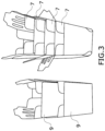
- Figure 3 shows the advantageous stacking ability of the expandable tray (7) compared to another trapezoid-shaped tray design (9) in which the angle of inclination of its walls is less pronounced to increase its capacity.
- the expandable tray (7) allows configuring its walls with an angle of inclination for stacking that optimizes logistics compared to other trays with the same capacity and height.
Landscapes
- Engineering & Computer Science (AREA)
- Mechanical Engineering (AREA)
- Stackable Containers (AREA)
- Cartons (AREA)
- Vehicle Step Arrangements And Article Storage (AREA)
- Table Devices Or Equipment (AREA)
- Buffer Packaging (AREA)
Abstract
Description
- An object of the present invention relates to an expandable tray, where tray is understood to mean a container in the form of a tray formed by a base and several side walls emerging from each side of the base, where the tray has the property of having an expandable inner volume as a result of the expansion of the base with the side walls.
- The present invention is characterized by the special configuration and design of the die-cut and cut cardboard sheet which is used to form the tray, thereby achieving an expandable tray which can furthermore be stacked since they can fit one inside another.
- Therefore, the present invention is comprised within the field of containers, preferably cardboard containers, having a configuration in the form of a tray.
- Truncated pyramid-shaped product containers which can fit inside one another, such that they can be arranged in a fitted manner, in a smaller volume, are known in the state of the art. However, there is no known container which, while having the possibility of being able to fit one inside another, has the characteristic of increasing their inner volume.
- Packages that can increase in volume as a result of a series of parallel fold lines in the folding area of the side walls with the base are also known in the state of the art. However, all known packages with means such as those described have a right prismatic shaped configuration, which enables them to be arranged fitted one inside another.
- Therefore, an object of the present invention relates to developing a container that simultaneously has both characteristics, that is, on one hand, they can be fitted one inside another, thereby taking up a smaller volume when stacked, and they also have the particularity of being able to modify their inner volume as needed.
- The essential parts of the object of the present invention are described in the independent claim, and different embodiments are described in the dependent claims.
- The object of the present invention is an expandable tray the inner volume of which can expand when exerting a force on the upper edge of the side walls once the tray is formed; the tray therefore has a base, which is preferably rectangular, and it can have as many sides as desired, from each side of the base emerging a series of sections that will form the side walls of the tray, and where at least twofold lines parallel to one another are arranged at the junction end of at least one of the side walls of the tray with the base.
- The number of side walls in the tray, as well as the number of parallel fold lines arranged on the side walls at their junction with the base are in no case limiting.
- The double fold line arranged at the junction of each side wall provided with the possibility of widening or being displaced in relation to the base allows having a double inner volume, one corresponding to folding the side wall with respect to the base by means of a first fold line and a second volume corresponding to folding the side wall with respect to the base by means of a second fold line.
- When exerting pressure on the upper edge of the side walls once the tray is formed, the side walls will be displaced outwards, where the displacement takes place at the junction end of the side walls with the base, modifying its inner volume since the side walls are provided with several fold lines parallel to one another.
- In order to fit one formed tray in another and be stacked, taking up a smaller volume, the side walls of the tray have a trapezoid-shaped configuration, which results in a final truncated pyramid-shaped configuration of the tray.
- As a result of the described characteristics, a container in the form of a tray which offers two very useful operating characteristics simultaneously is achieved, that is, on one hand, it is able to modify its inner volume based on the pressure exerted on the upper edge of the side walls once the tray is formed, and on the other hand, the trays can be arranged in a fitted manner one inside another almost in their entirety, which allows a stack with a smaller final stack volume, as a result of the trapezoid-shaped configuration of the side walls.
- Unless otherwise indicated, all the technical and scientific elements used in the present specification have the meaning that a person skilled in the art to which this invention belongs will normally understand. Methods and materials that are similar or equivalent to those described in the specification can be used in the practice of the present invention.
- Throughout the description and claims, the word "comprises" and its variants do not intend to exclude other technical features, additives, components or steps. For the persons skilled in the art, other objects, advantages and features of the invention will be inferred in part from the description and in part from the practice of the invention.
- To complement the description that is being made and for the purpose of helping to better understand the features of the invention, according to a preferred practical embodiment thereof, a set of drawings is attached as an integral part of said description in which the following is depicted in an illustrative and nonlimiting manner.
-
Figure 1 shows the die-cut and cut cardboard sheet used to form the tray. -
Figure 2 shows a perspective view of the now formed tray. -
Figure 3 depicts two different designs of stacked trays: on the right, the trays object of the invention, and on the left, trays with walls that are also trapezoid-shaped, but with angles of inclination for fitting that are less pronounced. - In
Figure 1 , the die-cut and cut cardboard sheet which is used to form the tray can be seen, and as observed, it comprises a base (1). The base (1) can have as many sides as desired, preferably four, like in the embodiment shown. - There emerges from each side of the base (1) a trapezoid-shaped side wall which is narrower at the junction with the base than at its free edge, such that when the side walls are folded with respect to the base, a truncated pyramid-shaped assembly is formed which allows the fitted arrangement of one tray with respect to another.
- In the embodiment shown, the base (1) is rectangular and, therefore, there are four side walls, with there being two end walls (2) and two lateral walls (3)
- In the embodiment shown, the lateral walls (3) have extensions by way of flaps (3.1) which allow the junction with the end walls (2). Closing flaps (3.2) are also arranged on the free edge of the lateral walls (3).
- At least twofold lines are provided at the junction with the base on each side wall to be provided with the possibility of outward displacement of the side walls at their junction area with respect to the base. In the embodiment shown, there is a first fold line (4) made on each side of the base (1) and a second fold line (5) arranged parallel to the first fold line (4) and on the junction end of each side wall with the base (1).
- In the embodiment shown, it can be seen how a concavity (6) is formed in each of the corners formed between contiguous sides of the base, where said concavity is an optional and by no means limiting embodiment.
- In the embodiment shown, it can be seen how there are additional fold lines on the end walls (2), namely pre-cutting lines (8) arranged parallel to the second fold lines (5) and used for an outward expansion of the end walls (2) at the junction end of the end walls (2) with the base (1).
-
Figure 2 shows a tray that is formed and filled with a series of objects in which due to the action of an outer pressure or force outer exerted on the upper edge of the side walls once the tray is formed, an outward displacement of the side walls with respect to the base (1) has occurred at the junction end of the side walls with the base (1), subsequently increasing the volume. -
Figure 3 shows the advantageous stacking ability of the expandable tray (7) compared to another trapezoid-shaped tray design (9) in which the angle of inclination of its walls is less pronounced to increase its capacity. The expandable tray (7) allows configuring its walls with an angle of inclination for stacking that optimizes logistics compared to other trays with the same capacity and height.
Claims (6)
- An expandable tray, characterized in that it comprises a base (1), wherein there emerges from each side of the base (1) a trapezoid-shaped side wall which is narrower at the junction with the base than at its free edge, such that when the side walls are folded with respect to the base, a truncated pyramid-shaped assembly is formed, in addition, at least twofold lines are arranged parallel to one another at the junction with the base on each side wall which, after exerting a force or pressure on the upper edge, is to be provided with the possibility of outward displacement of the side walls at their junction area with respect to the base.
- The expandable tray according to claim 1, characterized in that the base (1) is rectangular and there are four side walls, two end walls (2) and two lateral walls (3) and all the side walls have means for the outward displacement of the side walls at their junction area with respect to the base.
- The expandable tray according to claim 1 or 2, characterized in that there are twofold lines on the side faces, a first fold line (4) arranged on the junction edge of each side wall with respect to the base (1) and a second fold line (5) arranged parallel to the first fold line (4).
- The expandable tray according to claim 1 or 2, characterized in that on the end walls, there are pre-cutting lines (8) arranged parallel to the second fold lines (5).
- The expandable tray according to any of the preceding claims, characterized in that the lateral walls (3) have extensions by way of flaps (3.1) which allow the junction with the end walls (2), with closing flaps (3.2) also being arranged on the free edge of the lateral walls (3).
- The expandable tray according to any of the preceding claims, characterized in that a concavity (6) is formed in each of the corners formed between contiguous sides of the base.
Applications Claiming Priority (1)
| Application Number | Priority Date | Filing Date | Title |
|---|---|---|---|
| ES202231452U ES1298715Y (en) | 2022-09-07 | 2022-09-07 | EXPANDABLE TRAY |
Publications (3)
| Publication Number | Publication Date |
|---|---|
| EP4335772A1 true EP4335772A1 (en) | 2024-03-13 |
| EP4335772B1 EP4335772B1 (en) | 2025-12-24 |
| EP4335772C0 EP4335772C0 (en) | 2025-12-24 |
Family
ID=85705080
Family Applications (1)
| Application Number | Title | Priority Date | Filing Date |
|---|---|---|---|
| EP23194754.0A Active EP4335772B1 (en) | 2022-09-07 | 2023-09-01 | Expandable tray |
Country Status (2)
| Country | Link |
|---|---|
| EP (1) | EP4335772B1 (en) |
| ES (2) | ES1298715Y (en) |
Citations (5)
| Publication number | Priority date | Publication date | Assignee | Title |
|---|---|---|---|---|
| US2279670A (en) * | 1939-04-07 | 1942-04-14 | Fibreboard Products Inc | Box |
| EP0240628A1 (en) * | 1986-04-09 | 1987-10-14 | Vazics, Ltd. | Flower package apparatus |
| FR2723069A1 (en) * | 1994-07-29 | 1996-02-02 | Sapso Sa | Nested reusable containers |
| KR20110117349A (en) * | 2010-04-21 | 2011-10-27 | 박정희 | Popcorn containers |
| KR20210004014A (en) * | 2019-07-03 | 2021-01-13 | 박지현 | Disposable container |
-
2022
- 2022-09-07 ES ES202231452U patent/ES1298715Y/en active Active
-
2023
- 2023-09-01 EP EP23194754.0A patent/EP4335772B1/en active Active
- 2023-09-01 ES ES23194754T patent/ES3058984T3/en active Active
Patent Citations (5)
| Publication number | Priority date | Publication date | Assignee | Title |
|---|---|---|---|---|
| US2279670A (en) * | 1939-04-07 | 1942-04-14 | Fibreboard Products Inc | Box |
| EP0240628A1 (en) * | 1986-04-09 | 1987-10-14 | Vazics, Ltd. | Flower package apparatus |
| FR2723069A1 (en) * | 1994-07-29 | 1996-02-02 | Sapso Sa | Nested reusable containers |
| KR20110117349A (en) * | 2010-04-21 | 2011-10-27 | 박정희 | Popcorn containers |
| KR20210004014A (en) * | 2019-07-03 | 2021-01-13 | 박지현 | Disposable container |
Also Published As
| Publication number | Publication date |
|---|---|
| EP4335772B1 (en) | 2025-12-24 |
| EP4335772C0 (en) | 2025-12-24 |
| ES3058984T3 (en) | 2026-03-16 |
| ES1298715Y (en) | 2023-06-16 |
| ES1298715U (en) | 2023-03-28 |
Similar Documents
| Publication | Publication Date | Title |
|---|---|---|
| EP2377767B1 (en) | Expandable food carton | |
| EP1919780B1 (en) | Octagonal bulk bin with self-locking gusset-fold bottom flaps | |
| US9611072B2 (en) | Modular interconnecting knockdown container system | |
| US20080083632A1 (en) | Board Blank for Producing a Packaging Corner, and Packaging Corner | |
| US10625898B2 (en) | Break pack container | |
| US20090272790A1 (en) | Collapsible carton | |
| US11319106B2 (en) | Leakproof and liquid-tight packaging box of corrugated board and method for fabricating it | |
| JP2013184730A (en) | Cardboard box | |
| EP4335772B1 (en) | Expandable tray | |
| US3222190A (en) | Merchandising package | |
| US4040560A (en) | Carton adapted to be stacked flat and snapped open | |
| JP3175443U (en) | Cardboard box | |
| JP6871608B2 (en) | Buffer partition member and packaging box using it | |
| US11780637B2 (en) | Container with improved breakdown features | |
| JP3625036B2 (en) | Container with flange | |
| JP2008100709A (en) | Simple assembly box | |
| EP3587292A1 (en) | Box template | |
| US20200156822A1 (en) | Partition and packing material therewith | |
| JP6881176B2 (en) | Packaging box and blank sheet | |
| US20230056914A1 (en) | Crush-tolerant container and blank and method for forming the same | |
| CA2884508A1 (en) | Product container and reinforcement for a product container | |
| JP7539016B2 (en) | Structure of cylindrical packaging cushioning material | |
| CN112173339B (en) | Packaging material | |
| JP7246350B2 (en) | Boxes with upper and lower lids | |
| JP2019156451A (en) | Buffer structure, cushioning member and packing box |
Legal Events
| Date | Code | Title | Description |
|---|---|---|---|
| PUAI | Public reference made under article 153(3) epc to a published international application that has entered the european phase |
Free format text: ORIGINAL CODE: 0009012 |
|
| STAA | Information on the status of an ep patent application or granted ep patent |
Free format text: STATUS: THE APPLICATION HAS BEEN PUBLISHED |
|
| AK | Designated contracting states |
Kind code of ref document: A1 Designated state(s): AL AT BE BG CH CY CZ DE DK EE ES FI FR GB GR HR HU IE IS IT LI LT LU LV MC ME MK MT NL NO PL PT RO RS SE SI SK SM TR |
|
| STAA | Information on the status of an ep patent application or granted ep patent |
Free format text: STATUS: REQUEST FOR EXAMINATION WAS MADE |
|
| 17P | Request for examination filed |
Effective date: 20240814 |
|
| RBV | Designated contracting states (corrected) |
Designated state(s): AL AT BE BG CH CY CZ DE DK EE ES FI FR GB GR HR HU IE IS IT LI LT LU LV MC ME MK MT NL NO PL PT RO RS SE SI SK SM TR |
|
| GRAP | Despatch of communication of intention to grant a patent |
Free format text: ORIGINAL CODE: EPIDOSNIGR1 |
|
| STAA | Information on the status of an ep patent application or granted ep patent |
Free format text: STATUS: GRANT OF PATENT IS INTENDED |
|
| INTG | Intention to grant announced |
Effective date: 20250812 |
|
| GRAS | Grant fee paid |
Free format text: ORIGINAL CODE: EPIDOSNIGR3 |
|
| GRAA | (expected) grant |
Free format text: ORIGINAL CODE: 0009210 |
|
| STAA | Information on the status of an ep patent application or granted ep patent |
Free format text: STATUS: THE PATENT HAS BEEN GRANTED |
|
| AK | Designated contracting states |
Kind code of ref document: B1 Designated state(s): AL AT BE BG CH CY CZ DE DK EE ES FI FR GB GR HR HU IE IS IT LI LT LU LV MC ME MK MT NL NO PL PT RO RS SE SI SK SM TR |
|
| REG | Reference to a national code |
Ref country code: CH Ref legal event code: F10 Free format text: ST27 STATUS EVENT CODE: U-0-0-F10-F00 (AS PROVIDED BY THE NATIONAL OFFICE) Effective date: 20251224 Ref country code: GB Ref legal event code: FG4D |
|
| REG | Reference to a national code |
Ref country code: DE Ref legal event code: R096 Ref document number: 602023010034 Country of ref document: DE |
|
| U01 | Request for unitary effect filed |
Effective date: 20260114 |
|
| U07 | Unitary effect registered |
Designated state(s): AT BE BG DE DK EE FI FR IT LT LU LV MT NL PT RO SE SI Effective date: 20260120 |
|
| REG | Reference to a national code |
Ref country code: ES Ref legal event code: FG2A Ref document number: 3058984 Country of ref document: ES Kind code of ref document: T3 Effective date: 20260316 |
|
| PG25 | Lapsed in a contracting state [announced via postgrant information from national office to epo] |
Ref country code: NO Free format text: LAPSE BECAUSE OF FAILURE TO SUBMIT A TRANSLATION OF THE DESCRIPTION OR TO PAY THE FEE WITHIN THE PRESCRIBED TIME-LIMIT Effective date: 20260324 |
|
| PG25 | Lapsed in a contracting state [announced via postgrant information from national office to epo] |
Ref country code: HR Free format text: LAPSE BECAUSE OF FAILURE TO SUBMIT A TRANSLATION OF THE DESCRIPTION OR TO PAY THE FEE WITHIN THE PRESCRIBED TIME-LIMIT Effective date: 20251224 |
|
| PG25 | Lapsed in a contracting state [announced via postgrant information from national office to epo] |
Ref country code: RS Free format text: LAPSE BECAUSE OF FAILURE TO SUBMIT A TRANSLATION OF THE DESCRIPTION OR TO PAY THE FEE WITHIN THE PRESCRIBED TIME-LIMIT Effective date: 20260324 |
|
| PG25 | Lapsed in a contracting state [announced via postgrant information from national office to epo] |
Ref country code: SM Free format text: LAPSE BECAUSE OF FAILURE TO SUBMIT A TRANSLATION OF THE DESCRIPTION OR TO PAY THE FEE WITHIN THE PRESCRIBED TIME-LIMIT Effective date: 20251224 |
|
| PG25 | Lapsed in a contracting state [announced via postgrant information from national office to epo] |
Ref country code: PL Free format text: LAPSE BECAUSE OF FAILURE TO SUBMIT A TRANSLATION OF THE DESCRIPTION OR TO PAY THE FEE WITHIN THE PRESCRIBED TIME-LIMIT Effective date: 20251224 |
|
| PG25 | Lapsed in a contracting state [announced via postgrant information from national office to epo] |
Ref country code: IS Free format text: LAPSE BECAUSE OF FAILURE TO SUBMIT A TRANSLATION OF THE DESCRIPTION OR TO PAY THE FEE WITHIN THE PRESCRIBED TIME-LIMIT Effective date: 20260424 |
|
| PG25 | Lapsed in a contracting state [announced via postgrant information from national office to epo] |
Ref country code: CZ Free format text: LAPSE BECAUSE OF FAILURE TO SUBMIT A TRANSLATION OF THE DESCRIPTION OR TO PAY THE FEE WITHIN THE PRESCRIBED TIME-LIMIT Effective date: 20251224 |
|
| PG25 | Lapsed in a contracting state [announced via postgrant information from national office to epo] |
Ref country code: SK Free format text: LAPSE BECAUSE OF FAILURE TO SUBMIT A TRANSLATION OF THE DESCRIPTION OR TO PAY THE FEE WITHIN THE PRESCRIBED TIME-LIMIT Effective date: 20251224 |