EP4335698A1 - Method for controlling the orientation of a light beam for a motor vehicle, and motor vehicle - Google Patents
Method for controlling the orientation of a light beam for a motor vehicle, and motor vehicle Download PDFInfo
- Publication number
- EP4335698A1 EP4335698A1 EP23196488.3A EP23196488A EP4335698A1 EP 4335698 A1 EP4335698 A1 EP 4335698A1 EP 23196488 A EP23196488 A EP 23196488A EP 4335698 A1 EP4335698 A1 EP 4335698A1
- Authority
- EP
- European Patent Office
- Prior art keywords
- motor vehicle
- light beam
- point
- path
- time interval
- Prior art date
- Legal status (The legal status is an assumption and is not a legal conclusion. Google has not performed a legal analysis and makes no representation as to the accuracy of the status listed.)
- Withdrawn
Links
- 238000000034 method Methods 0.000 title claims abstract description 20
- 230000008569 process Effects 0.000 claims description 7
- 230000003247 decreasing effect Effects 0.000 claims description 5
- 230000007246 mechanism Effects 0.000 description 5
- 230000009471 action Effects 0.000 description 2
- 230000000712 assembly Effects 0.000 description 1
- 238000000429 assembly Methods 0.000 description 1
- 238000010586 diagram Methods 0.000 description 1
- 230000014509 gene expression Effects 0.000 description 1
- 230000006872 improvement Effects 0.000 description 1
Images

Classifications
-
- B—PERFORMING OPERATIONS; TRANSPORTING
- B60—VEHICLES IN GENERAL
- B60Q—ARRANGEMENT OF SIGNALLING OR LIGHTING DEVICES, THE MOUNTING OR SUPPORTING THEREOF OR CIRCUITS THEREFOR, FOR VEHICLES IN GENERAL
- B60Q1/00—Arrangement of optical signalling or lighting devices, the mounting or supporting thereof or circuits therefor
- B60Q1/02—Arrangement of optical signalling or lighting devices, the mounting or supporting thereof or circuits therefor the devices being primarily intended to illuminate the way ahead or to illuminate other areas of way or environments
- B60Q1/04—Arrangement of optical signalling or lighting devices, the mounting or supporting thereof or circuits therefor the devices being primarily intended to illuminate the way ahead or to illuminate other areas of way or environments the devices being headlights
- B60Q1/06—Arrangement of optical signalling or lighting devices, the mounting or supporting thereof or circuits therefor the devices being primarily intended to illuminate the way ahead or to illuminate other areas of way or environments the devices being headlights adjustable, e.g. remotely-controlled from inside vehicle
- B60Q1/08—Arrangement of optical signalling or lighting devices, the mounting or supporting thereof or circuits therefor the devices being primarily intended to illuminate the way ahead or to illuminate other areas of way or environments the devices being headlights adjustable, e.g. remotely-controlled from inside vehicle automatically
- B60Q1/085—Arrangement of optical signalling or lighting devices, the mounting or supporting thereof or circuits therefor the devices being primarily intended to illuminate the way ahead or to illuminate other areas of way or environments the devices being headlights adjustable, e.g. remotely-controlled from inside vehicle automatically due to special conditions, e.g. adverse weather, type of road, badly illuminated road signs or potential dangers
-
- B—PERFORMING OPERATIONS; TRANSPORTING
- B60—VEHICLES IN GENERAL
- B60Q—ARRANGEMENT OF SIGNALLING OR LIGHTING DEVICES, THE MOUNTING OR SUPPORTING THEREOF OR CIRCUITS THEREFOR, FOR VEHICLES IN GENERAL
- B60Q1/00—Arrangement of optical signalling or lighting devices, the mounting or supporting thereof or circuits therefor
- B60Q1/02—Arrangement of optical signalling or lighting devices, the mounting or supporting thereof or circuits therefor the devices being primarily intended to illuminate the way ahead or to illuminate other areas of way or environments
- B60Q1/04—Arrangement of optical signalling or lighting devices, the mounting or supporting thereof or circuits therefor the devices being primarily intended to illuminate the way ahead or to illuminate other areas of way or environments the devices being headlights
- B60Q1/06—Arrangement of optical signalling or lighting devices, the mounting or supporting thereof or circuits therefor the devices being primarily intended to illuminate the way ahead or to illuminate other areas of way or environments the devices being headlights adjustable, e.g. remotely-controlled from inside vehicle
- B60Q1/08—Arrangement of optical signalling or lighting devices, the mounting or supporting thereof or circuits therefor the devices being primarily intended to illuminate the way ahead or to illuminate other areas of way or environments the devices being headlights adjustable, e.g. remotely-controlled from inside vehicle automatically
- B60Q1/12—Arrangement of optical signalling or lighting devices, the mounting or supporting thereof or circuits therefor the devices being primarily intended to illuminate the way ahead or to illuminate other areas of way or environments the devices being headlights adjustable, e.g. remotely-controlled from inside vehicle automatically due to steering position
-
- B—PERFORMING OPERATIONS; TRANSPORTING
- B60—VEHICLES IN GENERAL
- B60Q—ARRANGEMENT OF SIGNALLING OR LIGHTING DEVICES, THE MOUNTING OR SUPPORTING THEREOF OR CIRCUITS THEREFOR, FOR VEHICLES IN GENERAL
- B60Q2300/00—Indexing codes for automatically adjustable headlamps or automatically dimmable headlamps
- B60Q2300/10—Indexing codes relating to particular vehicle conditions
- B60Q2300/11—Linear movements of the vehicle
- B60Q2300/112—Vehicle speed
-
- B—PERFORMING OPERATIONS; TRANSPORTING
- B60—VEHICLES IN GENERAL
- B60Q—ARRANGEMENT OF SIGNALLING OR LIGHTING DEVICES, THE MOUNTING OR SUPPORTING THEREOF OR CIRCUITS THEREFOR, FOR VEHICLES IN GENERAL
- B60Q2300/00—Indexing codes for automatically adjustable headlamps or automatically dimmable headlamps
- B60Q2300/30—Indexing codes relating to the vehicle environment
- B60Q2300/32—Road surface or travel path
-
- B—PERFORMING OPERATIONS; TRANSPORTING
- B60—VEHICLES IN GENERAL
- B60Q—ARRANGEMENT OF SIGNALLING OR LIGHTING DEVICES, THE MOUNTING OR SUPPORTING THEREOF OR CIRCUITS THEREFOR, FOR VEHICLES IN GENERAL
- B60Q2300/00—Indexing codes for automatically adjustable headlamps or automatically dimmable headlamps
- B60Q2300/30—Indexing codes relating to the vehicle environment
- B60Q2300/32—Road surface or travel path
- B60Q2300/322—Road curvature
-
- F—MECHANICAL ENGINEERING; LIGHTING; HEATING; WEAPONS; BLASTING
- F21—LIGHTING
- F21W—INDEXING SCHEME ASSOCIATED WITH SUBCLASSES F21K, F21L, F21S and F21V, RELATING TO USES OR APPLICATIONS OF LIGHTING DEVICES OR SYSTEMS
- F21W2102/00—Exterior vehicle lighting devices for illuminating purposes
- F21W2102/10—Arrangement or contour of the emitted light
- F21W2102/17—Arrangement or contour of the emitted light for regions other than high beam or low beam
- F21W2102/19—Arrangement or contour of the emitted light for regions other than high beam or low beam for curves
Definitions
- the present invention relates to a method for controlling the orientation of a light beam for a motor vehicle and to a motor vehicle.
- Motor vehicles are known that comprise the following:
- Front lighting assemblies are also known that are operationally connected to the steering mechanism so as to orient the light beam on a horizontal plane and on one side of the motor vehicle, so as to enable the light beam to light a curved region of the road profile.
- the lighting assembly is rotated by an angle associated or coinciding with a steering angle imposed by the driver on the front wheels via the steering wheel of the steering mechanism.
- the driver turns their gaze towards the curved region of the road profile before driving the steering wheel.
- the driver visually perceives the curved region as still not lit right in the moments immediately preceding the actual setting of the steering action.
- the purpose of the present invention is to produce a method for controlling the orientation of a light beam for a motor vehicle, which makes it possible to meet the need mentioned above.
- the present invention also relates to a motor vehicle according to what is defined by claim 7.
- reference number 1 indicates a motor vehicle comprising a body 2 defining a passenger compartment 3 and a front lighting assembly 4.
- the lighting assembly 4 can be driven to generate a light beam F in a region in front of the motor vehicle 1.
- the lighting assembly 4 comprises a pair of headlamps 6 that can rotate around respective axes parallel to the axis Z, so as to rotate the orientation of the light beam F.
- the lighting assembly 4 comprises a pair of left and right units formed, each one, from multiple LED lights that can be selectively operated, so as to rotate the orientation of the light beam F.
- the motor vehicle 1 also comprises a processing unit 10 (only schematically illustrated in Figure 3 ) programmed to control the lighting assembly 4, so as to adjust the orientation of the light beam F on a plane orthogonal to the axis Z and arranged, in use, horizontally.
- a processing unit 10 (only schematically illustrated in Figure 3 ) programmed to control the lighting assembly 4, so as to adjust the orientation of the light beam F on a plane orthogonal to the axis Z and arranged, in use, horizontally.
- the processing unit 10 is programmed to adjust the orientation of the light beam F on both sides of the motor vehicle 1.
- the motor vehicle 1 also comprises, only schematically illustrated in Figure 3 :
- processing unit 10 is programmed ( Figure 2 ) for:
- the processing unit 10 is programmed to continuously process over time a value of an angle ⁇ of rotation of an axis A of the light beam F relative to the direction X of the motor vehicle 1, so as to light a region 40 of the path containing the point P p .
- the axis A indicates the symmetry axis of the two components of the light beams F generated by the respective headlamps 6 or unit of the lighting assembly 4.
- the map 17 comprises, among other things, multiple straight sections 30 (only one of which is illustrated, for simplicity, in Figure 2 ) and multiple curved sections 31 (only of which is illustrated for simplicity in Figure 2 ).
- the section 31 extends between one initial end 32 arranged at the end of the section 30 and one end 33 that is terminal with reference to the forward direction of the motor vehicle 1 along the path P.
- the processing unit 10 is programmed to:
- the distance d p is equal to the product of the time interval t p and the moving speed of the motor vehicle 1.
- the distance d p is measured along a curved abscissa s parallel to the path P.
- time interval t p represents how much earlier the axis A of the light beam F is rotated by an angle ⁇ relative to the moment when the motor vehicle 1 reaches the end 32 of the section 31.
- the processing unit 10 is also programmed for:
- the angle ⁇ is processed, in the example illustrated, as atan yPp xPp .
- the processing unit 10 comprises a storing stage 25 (only schematically illustrated in Figure 3 ) in which a table 26 (also only schematically illustrated in Figure 3 ) is stored, which associates multiple values of the time interval t p with the corresponding values of the speed of the motor vehicle 1.
- the table 26 associates increasing values of the time interval tp with the corresponding values of the moving speed of the motor vehicle 1 parallel to the axis X.
- the values of the time interval t p contained in the table 26 increase (decrease) with the decreasing (increasing) of the values of the moving speed of the motor vehicle 1 parallel to the axis X.
- the values of the time interval t p contained in the table 26 preferably increase (decrease) linearly as the values of the moving speed of the motor vehicle 1 parallel to the axis X decrease (increase).
- a piece of software is uploaded to the processing unit 10 and implements an algorithm that generates the value of the angle ⁇ as described earlier.
- the processing unit 10 continuously acquires over time the map 17 associated with the path P from the database 15 and the current position Q of the motor vehicle 1 from the device 16.
- the processing unit 10 also processes continuously over time the value of the angle ⁇ of rotation of the axis A of the light beam F so as to light the region 40 of the section 31 of the path P containing the point P p before the motor vehicle 1 reaches the end 32 of the section 31.
- the processing unit 10 defines the time interval t p based on the moving speed of the motor vehicle 1.
- the processing unit 10 also processes the value of the distance d p between the point P p and the motor vehicle 1 along the curved abscissa s parallel to the path P, based on the time interval t p and a moving speed of the motor vehicle 1.
- the processing unit 10 processes the coordinates xP p , yP p of said point P p relative to the motor vehicle 1 based on the distance d p measured along the curved abscissa s parallel to the path P; and rotates the axis A of the light beam F of the angle ⁇ relative to the direction X based on said coordinates xP p , yPp of said point P p , so as to light the region 40 of the section 31 containing the point P p .
- the processing unit 10 rotates the axis A of the light beam F so as to light the region 40 comprising the point P p defined based on the map 17 and the path 16, before the motor vehicle reaches the region 40 comprising the point P p .
- the light beam F illuminates the region 40 when the driver turns their gaze on the region 40 itself before the motor vehicle reaches the end 31 of the section 30.
Landscapes
- Engineering & Computer Science (AREA)
- Mechanical Engineering (AREA)
- Lighting Device Outwards From Vehicle And Optical Signal (AREA)
Abstract
A method for controlling the orientation of a light beam (F) for a motor vehicle (1) is described comprising the steps of i) adjusting the orientation of a light beam (F) arranged at the front relative to a normal forward moving direction of the motor vehicle (1); ii) acquiring a map (17) of a path (P) followed by said motor vehicle (1); iii) acquiring a current position (Q) of the motor vehicle (1) along the path (P); and iv) defining a point (P<sub>p</sub>) of the path (P) to which to orient the light beam (F), based on the map (17) and on the current position (Q); and v) rotating the light beam (F) relative to the motor vehicle (1) so as to light the point (P<sub>p</sub>) before the motor vehicle (1) reaches the point (P<sub>p</sub>).
Description
- This patent application claims priority from
Italian patent application no. 102022000018474 filed on 12 September, 2022 - The present invention relates to a method for controlling the orientation of a light beam for a motor vehicle and to a motor vehicle.
- Motor vehicles are known that comprise the following:
- a pair of front wheels;
- a steering mechanism comprising, in turn, a steering wheel that can be driven to rotate the front wheels so as to enable the motor vehicle to follow a curved trajectory; and
- a front lighting assembly designed to generate a light beam that lights the front zone of the motor vehicle.
- Front lighting assemblies are also known that are operationally connected to the steering mechanism so as to orient the light beam on a horizontal plane and on one side of the motor vehicle, so as to enable the light beam to light a curved region of the road profile.
- For example, according to a known solution, the lighting assembly is rotated by an angle associated or coinciding with a steering angle imposed by the driver on the front wheels via the steering wheel of the steering mechanism.
- In the sector, it is known that the driver anticipates with their gaze the driving trajectory set in relation to the steering action imposed on the steering mechanism via the steering wheel.
- As a result, the driver turns their gaze towards the curved region of the road profile before driving the steering wheel.
- Therefore, the driver visually perceives the curved region as still not lit right in the moments immediately preceding the actual setting of the steering action.
- This situation generates the risk that the driver does not readily, visually perceive any obstacles or people present in the curved region of the road profile towards which the motor vehicle is proceeding.
- There is a need, in the sector, to improve the comfort of the driver, enabling them to visually perceive, suitably in advance, the obstacles or people present in the curved region of the road profile.
- The purpose of the present invention is to produce a method for controlling the orientation of a light beam for a motor vehicle, which makes it possible to meet the need mentioned above.
- The above-mentioned purpose is achieved with the present invention, as it relates to a method for controlling the orientation of a light beam for a motor vehicle according to what is defined in
claim 1. - The present invention also relates to a motor vehicle according to what is defined by claim 7.
- In order to better understand the present invention, a non-limiting preferred embodiment thereof will now be described by way of example with reference to the accompanying drawings, in which:
-
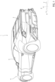
Figure 1 is a perspective view of a motor vehicle produced according to the present invention; -
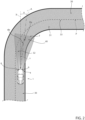
Figure 2 is a view from above of the motor vehicle inFigure 1 in a phase of driving along a straight region of a road path immediately preceding a curved region of the path itself; and -
Figure 3 is a functional diagram of some components of the motor vehicle inFigure 2 , with parts removed for clarity. - With reference to the attached figures,
reference number 1 indicates a motor vehicle comprising abody 2 defining apassenger compartment 3 and afront lighting assembly 4. - It should be specified that, below in this description, expressions such as "above", "below", "in front of", "behind" and the like are used with reference to the normal movement of the
motor vehicle 1. - It is also possible to define:
- a longitudinal axis X integral with the
motor vehicle 1, arranged, in use, horizontal and parallel to a normal forward moving direction of themotor vehicle 1; - a transversal axis Y integral with the
motor vehicle 1, arranged, in use, horizontal and orthogonal to the axis X; and - an axis Z integral with the
motor vehicle 1, arranged, in use, vertical and orthogonal to the axes X, Y. - The
lighting assembly 4 can be driven to generate a light beam F in a region in front of themotor vehicle 1. - In a first embodiment illustrated in
Figure 2 , thelighting assembly 4 comprises a pair ofheadlamps 6 that can rotate around respective axes parallel to the axis Z, so as to rotate the orientation of the light beam F. - In a second embodiment not illustrated, the
lighting assembly 4 comprises a pair of left and right units formed, each one, from multiple LED lights that can be selectively operated, so as to rotate the orientation of the light beam F. - The
motor vehicle 1 also comprises a processing unit 10 (only schematically illustrated inFigure 3 ) programmed to control thelighting assembly 4, so as to adjust the orientation of the light beam F on a plane orthogonal to the axis Z and arranged, in use, horizontally. - More specifically, the
processing unit 10 is programmed to adjust the orientation of the light beam F on both sides of themotor vehicle 1. - The
motor vehicle 1 also comprises, only schematically illustrated inFigure 3 : - a
database 15 comprisingmultiple maps 17 defining a road path P of themotor vehicle 1; and - a
device 16, for example a GPS receiver, able to acquire the current position of themotor vehicle 1 on the path P. - Advantageously, the
processing unit 10 is programmed (Figure 2 ) for: - acquiring a
map 17 of a path P followed by themotor vehicle 1 from thedatabase 15; - acquiring a current position Q of the
motor vehicle 1 along the path P from thedevice 16; - defining a point Pp of the path P to which to orient the light beam F, based on the
map 17 and on the above-mentioned current position Q; and - rotating the light beam F relative to the
motor vehicle 1 so as to light the point Pp before themotor vehicle 1 reaches the point Pp. - More specifically, the
processing unit 10 is programmed to continuously process over time a value of an angle θ of rotation of an axis A of the light beam F relative to the direction X of themotor vehicle 1, so as to light aregion 40 of the path containing the point Pp. - It is important to highlight that the rotation of the light beam F occurs without its being necessary to act on a steering mechanism of the
motor vehicle 1. - The axis A indicates the symmetry axis of the two components of the light beams F generated by the
respective headlamps 6 or unit of thelighting assembly 4. - In particular, the
map 17 comprises, among other things, multiple straight sections 30 (only one of which is illustrated, for simplicity, inFigure 2 ) and multiple curved sections 31 (only of which is illustrated for simplicity inFigure 2 ). - For illustrative simplicity, reference will be made, below in this description, to just one
section 30 and to theonly section 31 immediately subsequent to it along the path P. - With reference to
Figure 2 , thesection 31 extends between oneinitial end 32 arranged at the end of thesection 30 and oneend 33 that is terminal with reference to the forward direction of themotor vehicle 1 along the path P. - The
processing unit 10 is programmed to: - define a time interval (tp); and
- process a distance dp between the point Pp and the
motor vehicle 1, based on said time interval tp and on a moving speed of themotor vehicle 1. - More precisely, the distance dp is equal to the product of the time interval tp and the moving speed of the
motor vehicle 1. - The distance dp is measured along a curved abscissa s parallel to the path P.
- In particular, the time interval tp represents how much earlier the axis A of the light beam F is rotated by an angle θ relative to the moment when the
motor vehicle 1 reaches theend 32 of thesection 31. - The
processing unit 10 is also programmed for: - processing the coordinates xPp, yPp of said point Pp relative to the
motor vehicle 1 placed at a distance dp from the motor vehicle along the curved abscissa s parallel to the path P; and - controlling the
lighting assembly 4 to rotate the light beam F by the angle θ relative to themotor vehicle 1, based on said coordinates xPp, yPp of said point Pp so as to light theregion 40 of thesection 31 containing the point Pp . - The angle θ is processed, in the example illustrated, as

- In particular, the
processing unit 10 comprises a storing stage 25 (only schematically illustrated inFigure 3 ) in which a table 26 (also only schematically illustrated inFigure 3 ) is stored, which associates multiple values of the time interval tp with the corresponding values of the speed of themotor vehicle 1. - In the example illustrated, the table 26 associates increasing values of the time interval tp with the corresponding values of the moving speed of the
motor vehicle 1 parallel to the axis X. - In one embodiment, the values of the time interval tp contained in the table 26 increase (decrease) with the decreasing (increasing) of the values of the moving speed of the
motor vehicle 1 parallel to the axis X. - The values of the time interval tp contained in the table 26 preferably increase (decrease) linearly as the values of the moving speed of the
motor vehicle 1 parallel to the axis X decrease (increase). In particular, a piece of software is uploaded to theprocessing unit 10 and implements an algorithm that generates the value of the angle θ as described earlier. - The operation of the
motor vehicle 1 is described, at first, with reference to the condition ofFigure 2 , wherein themotor vehicle 1 follows astraight section 30 of the path P in the direction of thesection 31 immediately subsequent to the path P. - The
processing unit 10 continuously acquires over time themap 17 associated with the path P from thedatabase 15 and the current position Q of themotor vehicle 1 from thedevice 16. - The
processing unit 10 also processes continuously over time the value of the angle θ of rotation of the axis A of the light beam F so as to light theregion 40 of thesection 31 of the path P containing the point Pp before themotor vehicle 1 reaches theend 32 of thesection 31. - More specifically, the
processing unit 10 defines the time interval tp based on the moving speed of themotor vehicle 1. - The
processing unit 10 also processes the value of the distance dp between the point Pp and themotor vehicle 1 along the curved abscissa s parallel to the path P, based on the time interval tp and a moving speed of themotor vehicle 1. - Finally, the
processing unit 10 processes the coordinates xPp, yPp of said point Pp relative to themotor vehicle 1 based on the distance dp measured along the curved abscissa s parallel to the path P; and rotates the axis A of the light beam F of the angle θ relative to the direction X based on said coordinates xPp, yPp of said point Pp, so as to light theregion 40 of thesection 31 containing the point Pp. - The advantages enabled by the present invention will be apparent from an examination thereof.
- More specifically, the
processing unit 10 rotates the axis A of the light beam F so as to light theregion 40 comprising the point Pp defined based on themap 17 and thepath 16, before the motor vehicle reaches theregion 40 comprising the point Pp. - In this way, the light beam F illuminates the
region 40 when the driver turns their gaze on theregion 40 itself before the motor vehicle reaches theend 31 of thesection 30. - As a result, the risk that the driver does not see suitably in advance obstacles or people present in the
region 40 towards which themotor vehicle 1 is proceeding is largely avoided or at least reduced. - This results in a substantial improvement in the safety and comfort of driving associated with the
motor vehicle 1. - Finally, it is clear that changes may be made to the method and
motor vehicle 1, and variations produced thereto, according to the present invention that, in any case, do not depart from the scope of protection defined by the claims.
Claims (11)
- A method to control the orientation of a light beam (F) for a motor vehicle (1) comprising the steps of:i) adjusting the orientation of a light beam (F) arranged at the front relative to a normal forward moving direction of said motor vehicle (1);ii) acquiring a map (17) of a path (P) followed by said motor vehicle (1);iii) acquiring a current position (Q) of said motor vehicle (1) along said path (P); andiv) defining a point (Pp) of said path (P) to which to orient said light beam (F), based on said map (17) and on said current position (Q); andv) rotating said light beam (F) relative to said motor vehicle (1) so as to light said point (Pp) before said motor vehicle (1) reaches said point (Pp);said step iv) comprising the steps of:vi) defining a time interval (tp); andvii) processing a distance (dp) between said point (Pp) and said motor vehicle (1) along a curved abscissa (s) parallel to said path (P), based on said time interval (tp) and on a moving speed of said motor vehicle (1);characterized in that it comprises the step viii) of storing a table (26) associating said time interval (tp) with said moving speed of said motor vehicle (1);said table (26) associating increasing values of said time interval (tp) with corresponding decreasing values of said moving speed of said motor vehicle (1).
- The method according to claim 1, characterised in that said table (26) associates linearly increasing values of said time interval (tp) with corresponding, linearly decreasing values of said moving speed of said motor vehicle (1) .
- The method according to claim 1 or 2, characterized in that said step iv) comprises the steps of:ix) processing the coordinates (xPp, yPp) of said point (Pp) relative to said motor vehicle (1); andx) orienting said light beam (F) by an angle (θ) relative to a first, longitudinal axis (X) of said motor vehicle (1), based on said coordinates (xPp, yPp) of said point (Pp).
- The method according to any one of the preceding claims, characterized in that said step v) comprises the step xi) of rotating a headlamp and/or the step xii) of selectively turning on and off one or more LEDs of a lighting device (4).
- The method according to any of the previous claims, characterized in that said step v) comprises the step xiii) of orienting said light beam (F) in a plane orthogonal to a second axis (Z) of said motor vehicle (1); said second axis (Z) being orthogonal to said first longitudinal axis (X) of said motor vehicle (1) and orthogonal to a normal forward moving direction of said motor vehicle (1) and orthogonal to a third transverse axis (Y) of said motor vehicle (1) and orthogonal to said first axis (X).
- A computer product loadable into the memory of a processing unit (14) and capable of implementing, when it is executed, the steps of a method according to any one of the claims from 1 to 5.
- A motor vehicle (1) comprising:- a lighting device (4) designed to generate an orientable light beam (F) arranged at the front relative to a normal forward moving direction of said motor vehicle (1) ;- a database (15) comprising a map (17) of a path (P) followed, in use, by said motor vehicle (1);- acquisition means (16) acquiring a current position (Q) of said motor vehicle (1); and- a processing unit (10) programmed to adjust the orientation of said light beam (F);said processing unit (10) being programmed to:i) acquire said map (17) from said database (15);ii) acquire a current position (Q) of said motor vehicle (1) along said path (P) from said acquisition means (16);iii) define a point (Pp) of said path (P) to which to orient said light beam (F), based on said map (17) and on said current position (Q); andiv) rotate said light beam (F) relative to said motor vehicle (1) so as to light said point (Pp) before said motor vehicle (1) reaches said point (Pp);said processing unit (10) also being programmed to:- define a time interval (tp); and- process a distance (dp) between said point (Pp) and said motor vehicle (1) along a curved abscissa (s) parallel to said path (P), based on said time interval (tp) and on a moving speed of said motor vehicle (1);characterized in that said processing unit (10) comprises a storing stage (25), where a table (26) is stored, which associates said time interval (tp) with said moving speed of said motor vehicle (1);said table (26) associating increasing values of said time interval (tp) with corresponding decreasing values of said moving speed of said motor vehicle (1).
- The motor vehicle according to claim 7, characterized in that said processing unit (10) is further programmed to:- process the coordinates (xPp, yPp) of said point (Pp) relative to said motor vehicle (1); and- orient said light beam (F) with an angle (θ) relative to a fixed direction of said motor vehicle (1), based on said coordinates (xPp, yPp) of said point (Pp).
- The motor vehicle according to claim 7 or 8, characterized in that said lighting device (4) comprises, in turn:- an orientable headlamp (6); and/or- a plurality of LEDs, which can selectively be activated.
- The motor vehicle according to any of the claims from 7 to 9, characterized in that said light beam (F) is orientable in a plane orthogonal to a second axis (Z) of said motor vehicle (1); said second axis (Z) being orthogonal to said first longitudinal axis (X) of said motor vehicle (1), orthogonal to a normal forward moving direction of said motor vehicle (1), and orthogonal to a third transverse axis (Y) of said motor vehicle (1) and orthogonal to said first axis (X).
- The method according to any of claims 7 to 10, characterised in that said table (26) associates linearly increasing values of said time interval (tp) with corresponding, linearly decreasing values of said moving speed of said motor vehicle (1).
Applications Claiming Priority (1)
| Application Number | Priority Date | Filing Date | Title |
|---|---|---|---|
| IT102022000018474A IT202200018474A1 (en) | 2022-09-12 | 2022-09-12 | METHOD OF CONTROLLING THE ORIENTATION OF A LIGHT BEAM FOR A MOTOR VEHICLE AND MOTOR VEHICLE |
Publications (1)
| Publication Number | Publication Date |
|---|---|
| EP4335698A1 true EP4335698A1 (en) | 2024-03-13 |
Family
ID=84362548
Family Applications (1)
| Application Number | Title | Priority Date | Filing Date |
|---|---|---|---|
| EP23196488.3A Withdrawn EP4335698A1 (en) | 2022-09-12 | 2023-09-11 | Method for controlling the orientation of a light beam for a motor vehicle, and motor vehicle |
Country Status (3)
| Country | Link |
|---|---|
| US (1) | US20240083343A1 (en) |
| EP (1) | EP4335698A1 (en) |
| IT (1) | IT202200018474A1 (en) |
Citations (6)
| Publication number | Priority date | Publication date | Assignee | Title |
|---|---|---|---|---|
| US20020039295A1 (en) * | 2000-08-09 | 2002-04-04 | Koito Manufacturing Co., Ltd. | Vehicle headlamp system |
| US20090105912A1 (en) * | 2003-07-28 | 2009-04-23 | Denso Corporation | Automatic optical axis direction adjusting apparatus for vehicles |
| EP2181891A2 (en) * | 2008-10-30 | 2010-05-05 | Hella KG Hueck & Co. | Method and device for adjusting curve lighting headlights, particularly when driving through crossroads or confluences |
| US20120044708A1 (en) * | 2010-08-17 | 2012-02-23 | Visteon Global Technologies, Inc. | Predictive adaptive front lighting for a motor vehicle |
| KR101335630B1 (en) * | 2012-12-17 | 2013-12-03 | 주식회사 에스엘 서봉 | Apparatus and method for controlling lamp of vehicle |
| US20140098551A1 (en) * | 2012-10-04 | 2014-04-10 | Hella Kgaa Hueck & Co. | Method and device for setting a pivot angle of a headlamp when negotiating a bend |
Family Cites Families (12)
| Publication number | Priority date | Publication date | Assignee | Title |
|---|---|---|---|---|
| JP4601033B2 (en) * | 2000-12-27 | 2010-12-22 | 株式会社エクォス・リサーチ | Light distribution control device |
| JP2005239122A (en) * | 2004-01-29 | 2005-09-08 | Denso Corp | Automatic headlamp optical axis adjustment device for vehicles |
| JP4735179B2 (en) * | 2005-10-12 | 2011-07-27 | 株式会社デンソー | Vehicle control device |
| JP4682870B2 (en) * | 2006-02-24 | 2011-05-11 | 株式会社デンソー | Driving assistance device |
| DE102010040650B4 (en) * | 2010-09-13 | 2020-08-13 | Robert Bosch Gmbh | Device and method for adjusting the lighting of a vehicle in the case of blind bends |
| DE102011081367A1 (en) * | 2011-08-23 | 2013-02-28 | Robert Bosch Gmbh | Method for controlling a light emission of a headlamp of a vehicle |
| DE102014209771A1 (en) * | 2014-05-22 | 2015-11-26 | Hella Kgaa Hueck & Co. | Method for controlling a cornering light and lighting device |
| JP6728393B2 (en) * | 2016-11-29 | 2020-07-22 | ヤマハ発動機株式会社 | Angular velocity acquisition device around the vertical axis of the lean vehicle road surface |
| JP7184539B2 (en) * | 2018-05-24 | 2022-12-06 | スタンレー電気株式会社 | LIGHTING CONTROL DEVICE, VEHICLE LAMP, AND LIGHTING CONTROL METHOD |
| KR102132899B1 (en) * | 2018-10-08 | 2020-07-21 | 주식회사 만도 | Route Generation Apparatus at Crossroad, Method and Apparatus for Controlling Vehicle at Crossroad |
| DE102018219604A1 (en) * | 2018-11-15 | 2020-05-20 | Robert Bosch Gmbh | Method and control unit for setting a lighting range of at least one headlight of a vehicle |
| KR102808591B1 (en) * | 2019-12-31 | 2025-05-15 | 현대모비스 주식회사 | Lamp control apparatus for vehicle |
-
2022
- 2022-09-12 IT IT102022000018474A patent/IT202200018474A1/en unknown
-
2023
- 2023-09-07 US US18/462,995 patent/US20240083343A1/en not_active Abandoned
- 2023-09-11 EP EP23196488.3A patent/EP4335698A1/en not_active Withdrawn
Patent Citations (6)
| Publication number | Priority date | Publication date | Assignee | Title |
|---|---|---|---|---|
| US20020039295A1 (en) * | 2000-08-09 | 2002-04-04 | Koito Manufacturing Co., Ltd. | Vehicle headlamp system |
| US20090105912A1 (en) * | 2003-07-28 | 2009-04-23 | Denso Corporation | Automatic optical axis direction adjusting apparatus for vehicles |
| EP2181891A2 (en) * | 2008-10-30 | 2010-05-05 | Hella KG Hueck & Co. | Method and device for adjusting curve lighting headlights, particularly when driving through crossroads or confluences |
| US20120044708A1 (en) * | 2010-08-17 | 2012-02-23 | Visteon Global Technologies, Inc. | Predictive adaptive front lighting for a motor vehicle |
| US20140098551A1 (en) * | 2012-10-04 | 2014-04-10 | Hella Kgaa Hueck & Co. | Method and device for setting a pivot angle of a headlamp when negotiating a bend |
| KR101335630B1 (en) * | 2012-12-17 | 2013-12-03 | 주식회사 에스엘 서봉 | Apparatus and method for controlling lamp of vehicle |
Also Published As
| Publication number | Publication date |
|---|---|
| IT202200018474A1 (en) | 2024-03-12 |
| US20240083343A1 (en) | 2024-03-14 |
Similar Documents
| Publication | Publication Date | Title |
|---|---|---|
| DE102005036948B4 (en) | Vehicle headlight device | |
| US5931572A (en) | Head lamp device for vehicle | |
| DE102017214225B3 (en) | Method for operating a driver assistance system of a motor vehicle and motor vehicle | |
| US10399563B2 (en) | Driving support apparatus, driving support method, and computer program product | |
| US20180038568A1 (en) | Vehicular lighting apparatus | |
| EP2426034B1 (en) | Control system and control method for vehicles | |
| CN111824004B (en) | Light distribution control device for vehicle | |
| US7043342B1 (en) | Vehicle tracking driver assistance system | |
| DE102017117612A1 (en) | Automatic Driving System | |
| JP2009012608A (en) | Vehicle lighting device | |
| US20020001195A1 (en) | Vehicular lamp system for automotive vehicle | |
| EP3401157A1 (en) | Control method for riding a bicycle in a windshadow, control device and bicycle | |
| DE102009035634B4 (en) | Method for assisting a driver of a motor vehicle during a spin operation and corresponding motor vehicle | |
| EP4335698A1 (en) | Method for controlling the orientation of a light beam for a motor vehicle, and motor vehicle | |
| WO2016157891A1 (en) | Information presentation apparatus | |
| JP6614112B2 (en) | Headlight control device | |
| DE102005048398A1 (en) | Assistance system for a vehicle driver of a public vehicle feeds mission data such as theoretical speed, destination and safety distances to a computer which is programmed so that it generates a virtual vehicle | |
| KR101335630B1 (en) | Apparatus and method for controlling lamp of vehicle | |
| DE102009039324A1 (en) | Agricultural working machine with headlight | |
| JP2002225618A (en) | Headlight system for vehicle | |
| CN106274649A (en) | Intelligent automotive light control method and system | |
| JP6187541B2 (en) | Driving assistance device | |
| US11541804B2 (en) | Lighting device for a motor vehicle | |
| JP7144358B2 (en) | Cooperative traveling system for work vehicle and work vehicle | |
| CN114954644A (en) | Method for assisting a driver during a manual parking of a motor vehicle and motor vehicle |
Legal Events
| Date | Code | Title | Description |
|---|---|---|---|
| PUAI | Public reference made under article 153(3) epc to a published international application that has entered the european phase |
Free format text: ORIGINAL CODE: 0009012 |
|
| STAA | Information on the status of an ep patent application or granted ep patent |
Free format text: STATUS: THE APPLICATION HAS BEEN PUBLISHED |
|
| AK | Designated contracting states |
Kind code of ref document: A1 Designated state(s): AL AT BE BG CH CY CZ DE DK EE ES FI FR GB GR HR HU IE IS IT LI LT LU LV MC ME MK MT NL NO PL PT RO RS SE SI SK SM TR |
|
| STAA | Information on the status of an ep patent application or granted ep patent |
Free format text: STATUS: THE APPLICATION IS DEEMED TO BE WITHDRAWN |
|
| 18D | Application deemed to be withdrawn |
Effective date: 20240914 |