EP4335597A1 - Robotic tool and charging station - Google Patents
Robotic tool and charging station Download PDFInfo
- Publication number
- EP4335597A1 EP4335597A1 EP23172673.8A EP23172673A EP4335597A1 EP 4335597 A1 EP4335597 A1 EP 4335597A1 EP 23172673 A EP23172673 A EP 23172673A EP 4335597 A1 EP4335597 A1 EP 4335597A1
- Authority
- EP
- European Patent Office
- Prior art keywords
- charging
- column
- electrode
- charging terminal
- tool
- Prior art date
- Legal status (The legal status is an assumption and is not a legal conclusion. Google has not performed a legal analysis and makes no representation as to the accuracy of the status listed.)
- Pending
Links
Images




Classifications
-
- H—ELECTRICITY
- H02—GENERATION; CONVERSION OR DISTRIBUTION OF ELECTRIC POWER
- H02J—ELECTRIC POWER NETWORKS; CIRCUIT ARRANGEMENTS OR SYSTEMS FOR SUPPLYING OR DISTRIBUTING ELECTRIC POWER; SYSTEMS FOR STORING ELECTRIC ENERGY
- H02J7/00—Circuit arrangements for charging or discharging batteries or for supplying loads from batteries
- H02J7/70—Circuit arrangements for charging or discharging batteries or for supplying loads from batteries characterised by the mechanical construction
-
- H—ELECTRICITY
- H01—ELECTRIC ELEMENTS
- H01R—ELECTRICALLY-CONDUCTIVE CONNECTIONS; STRUCTURAL ASSOCIATIONS OF A PLURALITY OF MUTUALLY-INSULATED ELECTRICAL CONNECTING ELEMENTS; COUPLING DEVICES; CURRENT COLLECTORS
- H01R13/00—Details of coupling devices of the kinds covered by groups H01R12/70 or H01R24/00 - H01R33/00
- H01R13/02—Contact members
-
- A—HUMAN NECESSITIES
- A01—AGRICULTURE; FORESTRY; ANIMAL HUSBANDRY; HUNTING; TRAPPING; FISHING
- A01D—HARVESTING; MOWING
- A01D34/00—Mowers; Mowing apparatus of harvesters
- A01D34/006—Control or measuring arrangements
- A01D34/008—Control or measuring arrangements for automated or remotely controlled operation
-
- B—PERFORMING OPERATIONS; TRANSPORTING
- B25—HAND TOOLS; PORTABLE POWER-DRIVEN TOOLS; MANIPULATORS
- B25J—MANIPULATORS; CHAMBERS PROVIDED WITH MANIPULATION DEVICES
- B25J11/00—Manipulators not otherwise provided for
-
- B—PERFORMING OPERATIONS; TRANSPORTING
- B25—HAND TOOLS; PORTABLE POWER-DRIVEN TOOLS; MANIPULATORS
- B25J—MANIPULATORS; CHAMBERS PROVIDED WITH MANIPULATION DEVICES
- B25J11/00—Manipulators not otherwise provided for
- B25J11/005—Manipulators for mechanical processing tasks
- B25J11/0055—Cutting
-
- B—PERFORMING OPERATIONS; TRANSPORTING
- B25—HAND TOOLS; PORTABLE POWER-DRIVEN TOOLS; MANIPULATORS
- B25J—MANIPULATORS; CHAMBERS PROVIDED WITH MANIPULATION DEVICES
- B25J19/00—Accessories fitted to manipulators, e.g. for monitoring, for viewing; Safety devices combined with or specially adapted for use in connection with manipulators
-
- B—PERFORMING OPERATIONS; TRANSPORTING
- B25—HAND TOOLS; PORTABLE POWER-DRIVEN TOOLS; MANIPULATORS
- B25J—MANIPULATORS; CHAMBERS PROVIDED WITH MANIPULATION DEVICES
- B25J5/00—Manipulators mounted on wheels or on carriages
-
- B—PERFORMING OPERATIONS; TRANSPORTING
- B25—HAND TOOLS; PORTABLE POWER-DRIVEN TOOLS; MANIPULATORS
- B25J—MANIPULATORS; CHAMBERS PROVIDED WITH MANIPULATION DEVICES
- B25J5/00—Manipulators mounted on wheels or on carriages
- B25J5/007—Manipulators mounted on wheels or on carriages mounted on wheels
-
- B—PERFORMING OPERATIONS; TRANSPORTING
- B60—VEHICLES IN GENERAL
- B60L—PROPULSION OF ELECTRICALLY-PROPELLED VEHICLES; SUPPLYING ELECTRIC POWER FOR AUXILIARY EQUIPMENT OF ELECTRICALLY-PROPELLED VEHICLES; ELECTRODYNAMIC BRAKE SYSTEMS FOR VEHICLES IN GENERAL; MAGNETIC SUSPENSION OR LEVITATION FOR VEHICLES; MONITORING OPERATING VARIABLES OF ELECTRICALLY-PROPELLED VEHICLES; ELECTRIC SAFETY DEVICES FOR ELECTRICALLY-PROPELLED VEHICLES
- B60L53/00—Methods of charging batteries, specially adapted for electric vehicles; Charging stations or on-board charging equipment therefor; Exchange of energy storage elements in electric vehicles
- B60L53/10—Methods of charging batteries, specially adapted for electric vehicles; Charging stations or on-board charging equipment therefor; Exchange of energy storage elements in electric vehicles characterised by the energy transfer between the charging station and the vehicle
- B60L53/14—Conductive energy transfer
- B60L53/16—Connectors, e.g. plugs or sockets, specially adapted for charging electric vehicles
-
- B—PERFORMING OPERATIONS; TRANSPORTING
- B60—VEHICLES IN GENERAL
- B60L—PROPULSION OF ELECTRICALLY-PROPELLED VEHICLES; SUPPLYING ELECTRIC POWER FOR AUXILIARY EQUIPMENT OF ELECTRICALLY-PROPELLED VEHICLES; ELECTRODYNAMIC BRAKE SYSTEMS FOR VEHICLES IN GENERAL; MAGNETIC SUSPENSION OR LEVITATION FOR VEHICLES; MONITORING OPERATING VARIABLES OF ELECTRICALLY-PROPELLED VEHICLES; ELECTRIC SAFETY DEVICES FOR ELECTRICALLY-PROPELLED VEHICLES
- B60L53/00—Methods of charging batteries, specially adapted for electric vehicles; Charging stations or on-board charging equipment therefor; Exchange of energy storage elements in electric vehicles
- B60L53/30—Constructional details of charging stations
-
- B—PERFORMING OPERATIONS; TRANSPORTING
- B60—VEHICLES IN GENERAL
- B60L—PROPULSION OF ELECTRICALLY-PROPELLED VEHICLES; SUPPLYING ELECTRIC POWER FOR AUXILIARY EQUIPMENT OF ELECTRICALLY-PROPELLED VEHICLES; ELECTRODYNAMIC BRAKE SYSTEMS FOR VEHICLES IN GENERAL; MAGNETIC SUSPENSION OR LEVITATION FOR VEHICLES; MONITORING OPERATING VARIABLES OF ELECTRICALLY-PROPELLED VEHICLES; ELECTRIC SAFETY DEVICES FOR ELECTRICALLY-PROPELLED VEHICLES
- B60L53/00—Methods of charging batteries, specially adapted for electric vehicles; Charging stations or on-board charging equipment therefor; Exchange of energy storage elements in electric vehicles
- B60L53/30—Constructional details of charging stations
- B60L53/31—Charging columns specially adapted for electric vehicles
-
- B—PERFORMING OPERATIONS; TRANSPORTING
- B60—VEHICLES IN GENERAL
- B60L—PROPULSION OF ELECTRICALLY-PROPELLED VEHICLES; SUPPLYING ELECTRIC POWER FOR AUXILIARY EQUIPMENT OF ELECTRICALLY-PROPELLED VEHICLES; ELECTRODYNAMIC BRAKE SYSTEMS FOR VEHICLES IN GENERAL; MAGNETIC SUSPENSION OR LEVITATION FOR VEHICLES; MONITORING OPERATING VARIABLES OF ELECTRICALLY-PROPELLED VEHICLES; ELECTRIC SAFETY DEVICES FOR ELECTRICALLY-PROPELLED VEHICLES
- B60L53/00—Methods of charging batteries, specially adapted for electric vehicles; Charging stations or on-board charging equipment therefor; Exchange of energy storage elements in electric vehicles
- B60L53/30—Constructional details of charging stations
- B60L53/35—Means for automatic or assisted adjustment of the relative position of charging devices and vehicles
-
- B—PERFORMING OPERATIONS; TRANSPORTING
- B60—VEHICLES IN GENERAL
- B60L—PROPULSION OF ELECTRICALLY-PROPELLED VEHICLES; SUPPLYING ELECTRIC POWER FOR AUXILIARY EQUIPMENT OF ELECTRICALLY-PROPELLED VEHICLES; ELECTRODYNAMIC BRAKE SYSTEMS FOR VEHICLES IN GENERAL; MAGNETIC SUSPENSION OR LEVITATION FOR VEHICLES; MONITORING OPERATING VARIABLES OF ELECTRICALLY-PROPELLED VEHICLES; ELECTRIC SAFETY DEVICES FOR ELECTRICALLY-PROPELLED VEHICLES
- B60L53/00—Methods of charging batteries, specially adapted for electric vehicles; Charging stations or on-board charging equipment therefor; Exchange of energy storage elements in electric vehicles
- B60L53/60—Monitoring or controlling charging stations
-
- G—PHYSICS
- G05—CONTROLLING; REGULATING
- G05D—SYSTEMS FOR CONTROLLING OR REGULATING NON-ELECTRIC VARIABLES
- G05D1/00—Control of position, course, altitude or attitude of land, water, air or space vehicles, e.g. using automatic pilots
- G05D1/20—Control system inputs
- G05D1/24—Arrangements for determining position or orientation
- G05D1/247—Arrangements for determining position or orientation using signals provided by artificial sources external to the vehicle, e.g. navigation beacons
-
- G—PHYSICS
- G05—CONTROLLING; REGULATING
- G05D—SYSTEMS FOR CONTROLLING OR REGULATING NON-ELECTRIC VARIABLES
- G05D1/00—Control of position, course, altitude or attitude of land, water, air or space vehicles, e.g. using automatic pilots
- G05D1/60—Intended control result
- G05D1/656—Interaction with payloads or external entities
- G05D1/661—Docking at a base station
-
- H—ELECTRICITY
- H01—ELECTRIC ELEMENTS
- H01R—ELECTRICALLY-CONDUCTIVE CONNECTIONS; STRUCTURAL ASSOCIATIONS OF A PLURALITY OF MUTUALLY-INSULATED ELECTRICAL CONNECTING ELEMENTS; COUPLING DEVICES; CURRENT COLLECTORS
- H01R13/00—Details of coupling devices of the kinds covered by groups H01R12/70 or H01R24/00 - H01R33/00
- H01R13/40—Securing contact members in or to a base or case; Insulating of contact members
-
- H—ELECTRICITY
- H01—ELECTRIC ELEMENTS
- H01R—ELECTRICALLY-CONDUCTIVE CONNECTIONS; STRUCTURAL ASSOCIATIONS OF A PLURALITY OF MUTUALLY-INSULATED ELECTRICAL CONNECTING ELEMENTS; COUPLING DEVICES; CURRENT COLLECTORS
- H01R13/00—Details of coupling devices of the kinds covered by groups H01R12/70 or H01R24/00 - H01R33/00
- H01R13/648—Protective earth or shield arrangements on coupling devices, e.g. anti-static shielding
-
- H—ELECTRICITY
- H02—GENERATION; CONVERSION OR DISTRIBUTION OF ELECTRIC POWER
- H02J—ELECTRIC POWER NETWORKS; CIRCUIT ARRANGEMENTS OR SYSTEMS FOR SUPPLYING OR DISTRIBUTING ELECTRIC POWER; SYSTEMS FOR STORING ELECTRIC ENERGY
- H02J7/00—Circuit arrangements for charging or discharging batteries or for supplying loads from batteries
- H02J7/70—Circuit arrangements for charging or discharging batteries or for supplying loads from batteries characterised by the mechanical construction
- H02J7/751—Circuit arrangements for charging or discharging batteries or for supplying loads from batteries characterised by the mechanical construction concerning the insertion or the connection of the batteries
-
- B—PERFORMING OPERATIONS; TRANSPORTING
- B60—VEHICLES IN GENERAL
- B60L—PROPULSION OF ELECTRICALLY-PROPELLED VEHICLES; SUPPLYING ELECTRIC POWER FOR AUXILIARY EQUIPMENT OF ELECTRICALLY-PROPELLED VEHICLES; ELECTRODYNAMIC BRAKE SYSTEMS FOR VEHICLES IN GENERAL; MAGNETIC SUSPENSION OR LEVITATION FOR VEHICLES; MONITORING OPERATING VARIABLES OF ELECTRICALLY-PROPELLED VEHICLES; ELECTRIC SAFETY DEVICES FOR ELECTRICALLY-PROPELLED VEHICLES
- B60L2200/00—Type of vehicles
- B60L2200/40—Working vehicles
-
- G—PHYSICS
- G05—CONTROLLING; REGULATING
- G05D—SYSTEMS FOR CONTROLLING OR REGULATING NON-ELECTRIC VARIABLES
- G05D2105/00—Specific applications of the controlled vehicles
- G05D2105/15—Specific applications of the controlled vehicles for harvesting, sowing or mowing in agriculture or forestry
-
- G—PHYSICS
- G05—CONTROLLING; REGULATING
- G05D—SYSTEMS FOR CONTROLLING OR REGULATING NON-ELECTRIC VARIABLES
- G05D2107/00—Specific environments of the controlled vehicles
- G05D2107/20—Land use
- G05D2107/23—Gardens or lawns
-
- G—PHYSICS
- G05—CONTROLLING; REGULATING
- G05D—SYSTEMS FOR CONTROLLING OR REGULATING NON-ELECTRIC VARIABLES
- G05D2109/00—Types of controlled vehicles
- G05D2109/10—Land vehicles
-
- G—PHYSICS
- G05—CONTROLLING; REGULATING
- G05D—SYSTEMS FOR CONTROLLING OR REGULATING NON-ELECTRIC VARIABLES
- G05D2111/00—Details of signals used for control of position, course, altitude or attitude of land, water, air or space vehicles
- G05D2111/30—Radio signals
- G05D2111/36—Radio signals generated or reflected by cables or wires carrying current, e.g. boundary wires or leaky feeder cables
Definitions
- the embodiments described herein related to a robotic tool, and more specifically to a charging station for use with the robotic tool.
- Robot tools are typically used with some form of charging station to allow the tool to recharge any internal batteries from time to time.
- a charging station for use with a robotic tool, the charging station including a first column defining a first column axis, a second column defining a second column axis.
- the charging station also including a first charging terminal pivotably coupled to the first column for rotation about the first column axis, where the first charging terminal includes at least one electrode, and a second charging terminal pivotably coupled to the second column for rotation about the second column axis, where the second charging terminal includes at least one electrode.
- At least one of the first charging terminal and the second charging terminal includes a plurality of horizontally stacked portions.
- first charging terminal and the second charging terminal includes a first portion forming a first surface, a second portion forming a second surface opposite the first surface, and a third portion positioned between the first portion and the second portion.
- first portion and the second portion are formed from a conductive material
- third portion is formed from an insulating material
- one of the first surface and the second surface forms a positive electrode and the other of the first surface and the second surface forms a ground electrode.
- the at least one electrode of the first charging terminal has an opposite polarity of the at least one electrode of the second charging terminal.
- controller can change the polarity of the at least one electrode of the first charging terminal and the at least one electrode of the second charging terminal.
- the robotic tool can access the charging station from a first direction and a second direction opposite of the first direction
- the controller changes the polarity based on whether the robotic tool accesses the charging station from the first direction or the second direction.
- a robotic tool including a body having an outer surface, the body having a front end, a first side end extending from the front end, and a second side end extending from the front end opposite the first side end, one or more driven wheels coupled to the body, a working tool coupled to the body, a battery; and a positive charging plate.
- the positive charging plate including a first portion extending partially along the front end of the body, a second portion extending at least partially along the first side of the body, and a ground charging plate including a third portion extending partially along the front end of the body, and a fourth portion extending at least partially along the second side of the body.
- the positive charging plate and the ground charging plate are substantially identical in size and shape.
- the second portion of the positive charging plate has a greater surface area than the first portion of the positive charging plate.
- the fourth portion of the ground charging plate has a greater surface area than the third portion of the ground charging plate.
- ground charging plate has a greater total surface area than the total surface area of the positive charging plate.
- the working tool is a rotating blade.
- a robotic tool kit including a charging station including a first column defining a first column axis, and a first charging terminal pivotally coupled to the first column for rotation about the first column axis, where the first charging terminal extends radially outwardly from the first column to produce at least one electrode.
- the robotic kit also including a robotic tool including a body having an exterior surface, at least one driven wheel coupled to the body, a battery, and a first charging plate open to the exterior surface of the body, where the first charging plate is configured to contact and form an electrical connection with the at least one electrode.
- the at least one electrode of the charging terminal is located over a first vertical height range from a support surface
- the first charging plate is located over a second vertical height range from the support surface
- the first vertical height range overlaps with the second vertical height range
- the charging terminal includes a front surface and a back surface, and wherein one of the front surface and the back surface forms the positive electrode and the other of the back surface and the front surface forms the ground electrode.
- a second charging plate coupled and open to the exterior surface of the body, a second column defining a second column axis, a second charging terminal pivotably coupled to the second column for rotation about the second column axis, where the second charging terminal extends radially outwardly from the second column to produce at least one electrode.
- first charging terminal and the second charging terminal are positioned a first distance from a support surface
- first charging plate and the second charging plate are positioned a second distance from the support surface
- first distance is the same as the second distance
- the charging terminal can rotate about the first column axis in a first direction and a second direction.
- Figures 1-3 illustrate a robotic tool 10. More specifically, the tool 10 includes a robotic lawn mower for use to cut vegetation such as grass in an enclosed cutting area 14.
- the cutting area 14 generally includes, but is not limited to, a continuous area of grass or other vegetation that is enclosed by one or more barriers 16.
- the barriers 16 include a series of electrified wires enclosing the cutting area 14 while in alternative embodiments different form of barrier may be used such as, but not limited to, walls, pavers, GPS data points, and the like. As shown in FIG. 1 , such barriers 16 may be used to enclose the overall cutting area 14 and/or to segregate one or more interior regions from the cutting area 14. While the illustrated tool 10 is a robotic mower, it is understood that in alternative embodiments other forms of robotic tool may be used including, but not limited to, a robotic trimmer, a robotic sprinkler, a robotic fertilizer spreader, and the like.
- the tool 10 is an electrically powered, self-propelled device that includes a body 18, a plurality of wheels 22 rotatably mounted to the body 18, a working tool 26 mounted to the body 18, a controller 30, a battery 32, and a pair of charging plates 80a, 80b.
- the body 18, in turn, includes a front or first end 34, rear or second end 38 opposite the first end 34, a right or first side 42, and a left or second side 46 opposite the first side 42.
- the body 18 also defines a longitudinal axis 50 extending along the length of the body 18 and centered between the first side 42 and the second side 46 (e.g., passing through both the first and second ends 34, 38).
- the body 18 also defines a lateral axis 54 extending along the width of the body 18 and centered between the first and second ends 34, 38 (e.g., passing through both the first and second sides 42, 46).
- the body 18 also defines a central axis 58 generally positioned at the intersection of the longitudinal and lateral axes 50, 54 and oriented perpendicular to both (e.g., in a generally vertical orientation).
- the tool 10 includes four wheels 22a, 22b, 22c, 22d, each rotatably coupled to the body 18 and configured to support the tool 10 for self-driven movement along a support surface 60 (e.g., the surface of the cutting area 14).
- the wheels 22a, 22b, 22c, 22d include two steerable, undriven wheels 22a, 22b and two non-steerable, driven wheels 22c, 22d.
- all or any sub-set of the wheels 22 may be driven and all or any sub-set of the wheels 22 may be steerable.
- steerable wheels are passive in nature (e.g., a caster-style wheel), it is understood that in alternative embodiments the steerable wheels 22a, 22b may be actively driven by the controller 30.
- the tool 10 may include more or fewer wheels 22 positioned in different arrangements about the tool 10.
- the wheels 22 may be replaced by other forms of propulsion such as, but not limited to, tracks, omni-wheels, walking legs, and the like.
- the working tool 26 includes a rotating blade mounted for relative rotation about a blade axis 72. More specifically, the blade 26 is mounted to a dedicated blade motor 76 which rotates the blade 26 during use.
- the blade axis 72 is oriented vertically (e.g., parallel to the central axis 58) and positioned proximate the center of the body 18. In some embodiments, the blade axis 72 may be coincident with the central axis 58. While the illustrated working tool 26 is a rotating blade, it is understood that in alternative embodiments the tool 26 may include, but is not limited to, reciprocating blades, a distributor or dispenser of some kind, and the like.
- the tool 10 also includes a pair of charging plates 80a, 80b accessible from the exterior of the body 18 and in operable communication with at least one of the controller 30 and the battery 32 of the tool 10.
- the charging plates 80a, b are configured to create a temporary electrical connection with a charging station 84 (described below) to convey the electrical energy output by the charging station 84 to the battery 32 for recharging operations.
- each charging plate 80a, 80b includes a piece of conductive material applied to or embedded in the exterior surface of the body 18 of the tool 10 to form a corresponding electrode 92, 96.
- the charging plates 80a, 80b are positioned on the exterior of the body 18 so that a pair of charging terminals 100, 101 of the charging station 84 can contact the charging plates 80a, 80b as the tool 10 engages the charging station 84 and form the desired temporary electrical connection therebetween. Since only surface contact between the plates 80a, 80b and the charging station 84 is required, less precision is needed when docking the tool 10 with the charging station 84 as an exact lateral and vertical alignment is not required.
- the pair of charging plates 80a, 80b include a first charging plate 80a and a second charging plate 80b. More specifically, the first charging plate 80a includes a first section 110 extending along a portion of the front end 34 of the body 18 and a second section 114 extending along a portion of the first side 42 of the body 18 to generally encompass the front-right corner of the body 18 (see FIG. 5 ).
- the second charging plate 80b includes a first section 110 extending along a portion of the front end 34 of the body 18 and a second section 114 extending along a portion of the second side 46 of the body 18 to generally encompass the front-left corner of the body 18.
- one or both of the charging plates 80a, 80b may be disposed only on the front end 34 or only on the sides 42, 46 of the body 18 to alter the exact point at which the charging station 84 forms an electrical connection therewith.
- the second section 114 of the first and second charging plates 80a, 80b may be larger in size than the first section 110 of the first and second charging plates 80a, 80b.
- the first and second sections 110, 114 may be continuous (e.g., the charging plates 80 encompass the corners) or the sections 110, 114 may be separated by a space.
- a single electrode may be embodied in multiple plates positioned along the body 18.
- the charging plates 80a, 80b are flush with the front end 34 and the sides 42, 46 of the body 18.
- one or both of the charging plates 80a, 80b may extend outwardly beyond the body 18 to form a raised surface on the front end 34 and/or the sides 42, 46 of the body 18 (see FIG. 4 ).
- the charging plates 80a, 80b may include a curve or contour to help facilitate interaction with the charging terminals 100, 101.
- the charging plates 80a, 80b may smoothly transition between the first section 110 and the second section 114 to produce an exterior radius.
- the charging terminals 100, 101 may smoothly travel along the charging plates 80a, 80b while transitioning from contact with the first section 110 to contact with the second section 114.
- the first charging plate 80a and the second charging plate 80b may be identical in shape and size, or the charging plates 80a, 80b could differ in shape and size (discussed below).
- the pair of charging plates 80a, 80b are positioned at a constant vertical charger height 126.
- the pair of charging plates 80a, 80b are each made from a conductive material, such as metal. As such, the first charging plate 80a forms a first or positive electrode 92 while the second charging plate 80b forms a second or ground electrode 96. However, the polarities may be reversed in some embodiments. For safety, there is a space between the first charging plate 80a and the second charging plate 80b. The space between the first charging plate 80a and the second charging plate 80b may be made of an insulating material.
- the second charging plate 1080b is configured to engage with the charging station 84 before the first charging plate 1080a (see FIG. 6 ). By doing so, the ground electrode 96 may come into contact with the charging station 84 before the positive electrode 92. This orientation increases safety as it causes the tool 10 to become grounded (i.e., via the ground electrode 96) before the positive electrode 92 is electrically coupled during the docking process. More specifically, in the illustrated embodiment the second charging plate 1080b includes both a first and second section 110, 114 while the first charging plate 1080a only includes a second section 114.
- a tool traveling in a forward direction V would cause the second charging plate 1080b to make an electrical connection with the charging station 84 before the first charging plate 1080a as the second charging plate 1080b is positioned further forward in the direction of travel V and closer to the first end 34.
- FIG. 7 illustrates a charging station 84 for use with the tool 10. More specifically, the charging station 84 is configured to provide an electrical interface against which the pair of charging plates 80a, b of the tool 10 can interact to form an electrical connection therebetween.
- the charging station 84 includes a support pad 148, a pair of support columns 142a, 142b, a station controller 146, and a pair of charging terminals 100, 101.
- the support pad 148 of the charging station 84 is configured to be positioned on the support surface 60 and forms a top surface 88 that is configured to allow the tool 10 to travel thereon.
- the support pad 148 defines a charging station axis 103 passing through both the first and second support columns 142a, 142b (described below) and a centerline axis 104 extending perpendicular to the charging station axis 103 and centered between the first and second support columns 142a, 142b.
- the centerline axis 104 defines a first direction A and a second direction B.
- the support pad 148 is rectangular in shape having a first end 150 and a second end 154 opposite the first end 150.
- the charging station axis 103 is parallel to both the first and second ends 150, 154 while the centerline axis 104 passes through both the first and second ends 150, 154.
- the support pad 148 is sized to at least partially support the tool 10 on the top surface 88 thereof. More specifically, the width of the support pad 148 is sized so that front end 34 of the body 18 of the tool 10 can be positioned on the support pad 148 such that both front wheels 22a, 22b can rest thereon simultaneously (see FIG. 11 ).
- the length of the support pad 148 can be sized to the length of the body 18 of the tool 10, or it may be shorter than the length of the body 18, so it only partially supports a portion of the tool 10 (e.g., only the front wheels 22a, 22b).
- the illustrated support pad 148 is rectangular, it is understood that in alternative embodiments different sizes and shapes may be present such as but not limited to circular, elliptical, polygonal, and the like. Additionally, the support pad may be made out of a variety of materials (e.g., rubber, hard plastic) so that the charging station 84 can be used on multiple terrains such as soft soils or hard concrete.
- materials e.g., rubber, hard plastic
- the pair of support columns 142a, 142b of the charging station 84 are each mounted to the support pad 148 and extend vertically upwardly from the top surfaced 88 to define a gate 144 having a gate width 145 therebetween.
- Each support column 142a, 142b also defines a corresponding support column axis 90a, 90b.
- each support column 142a, b is configured to pivotably support a respective one of the charging terminals 100, 101 thereon. More specifically, a first charging terminal 100 is pivotably mounted on the first support column 142a, and a second charging terminal 101 is pivotably mounted on the second support column 142b.
- the pair of support columns 142a, 142b are spaced apart so that the tool 10 can pass between the pair of support columns 142a, 142b (e.g., though the gate 144).
- the support columns 142a, 142b are cylindrical, however they can be a variety of shapes (e.g., rectangular cube, triangular prism, and the like).
- the support columns 142a, 142b are equidistant from the charging centerline 104.
- the pair of support columns 142a, 142b are secured on the support pad 148; however, in alternative embodiments the pair of support columns 142a, 142b may be removably mounted on the support pad 148. In still other embodiments, the support columns 142a, 142b may be directly placed on the support surface 60 individually with no support pad 148 being present.
- the first and second charging terminals 100, 101 of the charging station 84 are pivotably coupled to the first and second support columns 142a, 142b, respectively, for rotational movement about the corresponding column axes 90a, 90b.
- the charging terminals 100, 101 each include at least one of a positive or ground electrode 158, 162 in electrical communication with the station controller 146.
- the first and second charging terminals 100, 101 are configured so that as the tool 10 passes between the first and second support columns 142a, 142b (e.g., the tool 10 crosses the support column axis 103), the electrodes 158, 162 of the charging terminals 100, 101 engage and form an electrical connection with the corresponding electrodes 92, 96 formed by the pair of charging plates 80a, 80b of the tool 10.
- the first and second charging terminals 100, 101 each have a rectangular shaped body 174 that is generally oriented parallel to the corresponding column axes 90a, 90b in the vertical direction and radially oriented in the horizontal direction.
- the body 174 includes a first surface 178 and a second surface 182 opposite of the first surface 178.
- the body 174 is formed with three horizontally stacked sections.
- a first section 188 is formed from an electrically conductive material (e.g., metal) and forms the first surface 178
- a second section 192 is formed from an electrically conductive material (e.g., metal) and forms the second surface 182
- a third or insulating section 196 is positioned between and electrically isolating the first section 188 and the second section 192.
- the first section 188 of each charging terminal 100, 101 forms the positive electrode 158
- the second section 192 of each charging terminal 100, 101 forms the ground electrode 162.
- the two charging terminals 100, 101 are mounted to their respective support columns 142a, 142b in a mirrored configuration so that one positive electrode 158 and one ground electrode 162 (e.g., an electrical pair) are presented in both the first and second directions A, B.
- one positive electrode 158 and one ground electrode 162 e.g., an electrical pair
- the first surface 178 of the first charging terminal 100 faces the front end 150 of the support pad 148 (e.g., the first direction A) and the second surface 182 of the first charging terminal 100 faces the second end 154 of the support pad 148 (e.g., the second direction B), while the first surface 178 of the second charging terminal 101 faces the second end 154 of the support pad 148 (e.g., the second direction B) and the second surface 182 of the second charging terminal 101 faces the first end 150 (e.g., the first direction A).
- the positive electrode 158 of the first charging terminal 100 and the ground electrode 162 of the second charging terminal 101 face the first end 150 of the support pad 148, while the ground electrode 162 of the first charging terminal 100 and the positive electrode 158 of the second charging terminal 101 face the second end 154 of the support pad 148.
- the charging terminal 84 also includes a pair of biasing members 94.
- Each biasing member 94 extends between and is coupled to one of the charging terminals 100, 101, and the corresponding one of the support columns 142a, 142b. More specifically, each biasing member 94 is configured to bias the corresponding charging terminals 100, 101 into a rest or neutral position (see FIG. 7 ). During use, any forces applied to the charging terminals 100, 101 cause the terminals 100, 101 to pivot away from the rest position while removing the force allows the biasing member 94 to bias the terminals 100, 101 back into the rest position.
- the rest position for both the first and second charging terminals 100, 101 is where each terminal 100, 101 extends outwardly from its respective support column 142a, 142b along the charging station axis 103 towards the charging centerline 104 (see FIG. 7 ).
- the two charging terminals 100, 101 act as a gate being positioned between the two support columns 142a, 142b along the station axis 103.
- the length of the charging terminals 100, 101 are sized such that both of the charging terminals 100, 101 can make contact with the tool 10 when the tool 10 is positioned between the support columns 142a, 142b, but sized so that the charging terminals 100, 101 do not make contact with each other.
- the first and second charging terminals 100, 101 are configured to independently pivot in both a clockwise and a counterclockwise direction about the support columns 142a, 142b upon the application of an external force (e.g., coming into contact with the body 18 of the tool 10).
- the charging terminals 100, 101 are configured so that as long as both the charging terminals 100, 101 make contact with a corresponding one of the pair of charging plates 80a, b, at any point along the length of the charging plates 80a, b, the desired electrical connections will be made (e.g., the positive electrode 92 of the charging plate 80a is in direct surface contact with the positive electrode 158 of the first or second charging terminal 100, 101 and the ground electrode 96 of the charging plate 80b is in direct surface contact with the ground electrode 162 of the first or second charging terminal 100, 101).
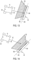
- the illustrated charging station 84 includes terminals 100, 101 where each terminal 100, 101 includes both a positive and a ground electrode 158, 162 on opposite sides thereof, it allows the tool 10 to access the charging station from either the first end 150 (see FIG. 13 ) or the second end 154 (see FIG. 15 ). More specifically, a tool 10 approaching the station 84 from the first direction A will be approaching a station 84 having a positive electrode 158 on the right side and a ground electrode 162 on the left side and a tool 10 approaching the station 84 from the second direction B will also be approaching a station 84 having a positive electrode 158 on the right side and a ground electrode 162 on the left side.
- the charging terminals 100, 101 can pivot it allows the tool 10 to enter from a variety of angles relative to the centerline 104 and still produce the required electrical contacts. More specifically, the charging station 84 is shaped so that the tool 10 may approach the station 84 from the first end 150 or the second end 154 along any approach vector V1 positioned within a pre-determined approach envelope 170, shown in FIG. 12 .
- the approach envelope 170 is generally defined as the range of approach angles, as measured from the charging centerline 104, at which the tool 10 can approach the station 84 and still make the desired electrical contacts.
- the approach envelope 170 generally includes a trapezoidal or frusto-conical region with its base resting along the charging station axis 103 within the gate 144 (e.g., within the gate width 145) and expanding outwardly at an expansion angle A1, A2 on both sides thereof relative to the centerline 104.
- the expansion angle A1, A2 is at least 89 degrees.
- the expansion angle A is at least 85 degrees, 80 degrees, 75 degrees, 70 degrees, 65 degrees, 60 degrees, 55 degrees, 50 degrees, and 45 degrees.
- both expansion angles A1, A2 are the same in the illustrated embodiment, it is understood that in other embodiments the different expansion angles A1, A2 may be different.
- the difference in angle A1, A2 may accommodate differences in terminal 100, 101 shape, differences in the layout of the charging plates 80a, 80 of the tool 10, and the like.
- such approach vectors V1 may include vectors traveling toward the center point of the gate 144 between the charging terminals 100, 101 from any direction within the approach envelope 170 (see FIG. 13 ).
- such approach vectors V2 may include vectors offset from the center point of the gap between the charging terminals 100, 101 but still falling within the approach envelope 170 and still passing between support columns 142a, 142b (see FIG. 14 ).
- the pivoting action of the terminals 100, 101 also allows a single terminal 84 to accommodate a variety of tools (not shown) having different widths and/or plate 80 layouts without having to alter or otherwise swap out the terminals 100, 101 themselves.
- the charging station 84 may also define one or more boundary wire envelopes 200a, 200b.
- a boundary wire envelope 200a, 200b is generally defined as the range of extension angles, as measured relative to the centerline 104, at which the boundary wire 16 may extend from the support pad 148 and still allow a tool 10 following the wire 16 to pass through the gate 144. More specifically, each envelope 200a, 200b corresponds to a respective wire segment 16a, 16b that extends from the support pad 148 at a given extension point 204a, 204b.
- charging station 84 includes a first wire segment 16a extending outwardly from the first end 150 of the support pad 148 at the first extension point 204a to define a first extension angle 208a and a second wire segment 16b extending outwardly from the second end 154 of the support pad 148 at the second extension point 204b.
- the first bound wire envelope 200a extends ⁇ 89 degrees from the first extension point 204a relative to a datum D that is parallel to the centerline axis 104.
- the first boundary wire envelope 200a may extend at least 85 degrees, 80 degrees, 75 degrees, 70 degrees, 65 degrees, 60 degrees, 55 degrees, 50 degrees, and 45 degrees.
- the illustrated embodiment extends equally in both directions relative to a datum D parallel to the centerline axis 104, it is understood that in other embodiments the envelope 200a may extend asymmetrically relative to the centerline axis 104.
- the second bound wire envelope 200b extends ⁇ 89 degrees from the second extension point 204b relative to a datum D that is parallel to the centerline axis 104.
- the second boundary wire envelope 200b may extend at least 85 degrees, 80 degrees, 75 degrees, 70 degrees, 65 degrees, 60 degrees, 55 degrees, 50 degrees, and 45 degrees.
- the illustrated embodiment extends equally in both directions relative to a datum parallel to the centerline axis 104, it is understood that in other embodiments the envelope 200b may extend asymmetrically relative to the centerline axis 104.
- the station controller 146 of the charging station 84 is in operable communication with at least the positive electrode 158 and the ground electrode 162 of the first and second charging terminal 100, 101 and is configured to control the flow of electrical power thereto. More specifically, the charging station 84 is in electrical communication with a power source (e.g., an internal or external battery, and/or utility power via a plug, and the like) and is configured to convey electrical power to the electrodes 158, 162 during the battery charging operation. While not shown, the first and second charging terminal 100, 101 may include additional electrodes electrically isolated from the positive and ground electrodes 158, 162 and configured to transmit additional electrical power and/or signals between charging station 84 and the tool 10.
- a power source e.g., an internal or external battery, and/or utility power via a plug, and the like
- the first and second charging terminal 100, 101 may include additional electrodes electrically isolated from the positive and ground electrodes 158, 162 and configured to transmit additional electrical power and/or signals between charging station 84 and the tool 10.
- the tool 10 is configured to travel across the support surface 60 and cut vegetation (e.g., grass).
- vegetation e.g., grass
- the controller 30 of the tool 10 may instruct the tool 10 to return to the charging station 84 to replenish the battery 32.
- the tool 10 may then maneuver toward the charging station 84 taking any approach vector V that falls within the approach envelope 170 (see FIG. 12 ).
- the tool 10 climbs onto the top surface 88 of the support pad 148 and begins to travel across the top surface 88 toward the axis 103.
- the first and second plates 80a, 80b Upon reaching the axis 103, the first and second plates 80a, 80b come into contact with the positive electrode 158 of the first terminal 100 and the ground electrode 162 of the second terminal 101, respectively, forming an electrical connection therebetween.
- the tool 10 may continue to travel in direction V pivoting the terminals 100, 101 out of their rest positions to make room for the tool 10 to pass therethrough.
- the biasing members 94 attempt to bias the terminals 100, 101 back into their rest position resulting in a compressive force maintaining the terminal 100, 101 in contact with the plates 80a, 80b.
- the station controller 146 can begin the charging process (e.g., conveying electrical power to the battery 32 of the tool 10 via the electrodes 92, 96, 158, 162).
- the controller 30 of the tool 10 may instruct the tool 10 to travel away from the charging station 84 so that the first and second charging terminals 100, 101 separates from the charging plates 80 and the electrical connections between the electrodes 92, 96, 158, 162 severed.
- the biasing members 84 return both charging terminals 100, 101 to their rest positions.
- the controller 30 of the tool 10 may include a program that instructs the tool 10 to approach the charging station 84 from a variety of approach vectors within the approach envelope 170 on subsequent trips to the charging station 84.
- the program allows the tool 10 to minimize the amount of damage done to the turf immediately surrounding the charging station 84 by assuring that no single area of turf is subject to excessive wear.
- the approach vectors may be randomly selected from a group of pre-calculated vectors.
- the varied approach vectors may be pre-determined or produce a recurring pattern.
- the controller 30 may be configured to instruct the tool 10 to approach the station 84 from the 2 o'clock position for the subsequent charging session.
- Such a program may also then instruct the tool 10 to approach the station 84 from the 5 o'clock position for the next charging session, and so on continuing to adjust the vector 45 degrees while staying in the approach envelope 170 for every charging session.
- FIG. 8 illustrates another embodiment of the charging station 1084.
- the charging station 1084 is substantially similar to the charging station 84 described above. As such, only the differences will be described in detail herein.
- the terminals 1100, 1101 are positions so that their rest positions are angularly offset from the axis 1103 so that the ground terminal 1162 is positioned forward of the axis 1103 and the positive terminals 1158 are positioned behind the axis 1103. By doing so, the terminals 1100, 1101 are oriented so that a tool 10 will engage the ground terminal 1162 before the positive terminal 1158. This makes the charging station 1084 safer as it makes sure to ground the tool 10 before the positive electrode 1158 is engaged. As shown in FIG. 8 , this layout assures the ground electrode 1162 will contact first regardless of the direction that the tool 10 approaches (e.g., from the first direction A or the second direction B).
- FIG. 16 illustrates another embodiment of the charging station 2084.
- the charging station 2084 is substantially similar to the charging station 84 described above, so only the differences will be described in detail herein.
- the charging station 2084 includes sensor 2198 disposed inside of the support pad 2148.
- the sensor 2198 may be placed proximate the first end 2150 or the second end 2154 of the charging station 2084, or the sensor 2198 might extend between the first end 2150 and the second end 2154.
- the sensor 2198 is configured to determine if the tool 10 is accessing the charging station 2084 from a first end 2150 or a second end 2154.
- the sensor 2198 may be a weight or a proximity sensor.
- the sensor 2198 is in communication with the controller 2146.
- the charging terminals 2100, 2101 are formed from a single layer made from a conductive material, such as metal.
- the controller 2146 controls and changes the polarity of the charging terminals 2100, 2101 so that the terminals 2100, 2101 always have opposite charges (e.g., the first charging terminal 2100 has a positive electrode 2158 and the second charging terminal 2101 has a ground electrode 2162).
- the controller 2146 changes the polarity of the charging terminals 2100, 2101 stations based on the information from the sensor 2198 to ensure that the positive electrode 92 connects with the positive electrode 2158 and that the ground electrode 96 connects with the ground electrode 2162.
- the controller 2146 If the sensor 2198 senses that the tool 10 is approaching the charging station 2084 from the first end 2150, the controller 2146 outputs signals so that the first charging terminal 2100 forms a positive terminal 2158 and the second charging terminal 2101 forms a ground terminal 2162. Alternatively, if the sensor 2198 senses that the tool 10 is approaching the charging station 2084 from the second end 2154, the controller 2146 outputs signals so that the second charging terminal 2101 forms a positive electrode 2158 and the first charging terminal 1100 forms the ground electrode 2162.
- FIG. 17 illustrates another embodiment of the charging station 3084.
- the charging station 3084 is substantially similar to the charging station 84 described above, so only the differences will be described in detail herein.
- the charging terminals 3100, 3101 are formed from two horizontally stacked sections.
- a first section 3188 is formed form an electrically conductive material (e.g., metal) and a second section 3192 is formed from an electrically insulating material (e.g., rubber and the like).
- the conductive section 3188 of the first terminal 3100 and the conductive section 3188 of the second terminal 3101 both face the same side (e.g., the first side 3150) of the support pad 3148. More specifically, one of the conductive section 3188 of the first terminal 3100 and conductive section 3188 of the second terminal 3101 serves as the positive electrode 3158 while the remaining conductive section 3188 serves as the ground or negative electrode 3162.
- a tool 10 approaching the terminal 3084 from the first end 3150 will be presented with a positive and ground electrode 3158, 3162 for forming the electrical connection.
- a tool 10 or other item approaching from the second end 3158 will be presented with two insulative surfaces unable to conduct electricity therewith.
- the layout of the terminal 3084 is uni-directional in the sense that it can only accommodate a tool 10 approaching from a single direction.
- the terminal 3084 also has a greater safety factor as the sides of the terminals 3100, 3101 facing the second end 3154 are insulated and therefore will not conduct electricity if accidentally touched or brushed against by a user, wildlife, and the like.
- FIG. 18 illustrates another embodiment of the charging station 4084.
- the charging station 4084 is substantially similar to the charging station 84 so only the differences will be discussed in detail herein.
- the charging station 4084 includes a single terminal 4100 coupled to a single support column 4142.
- the terminal 4100 includes three vertically stacked sections.
- a first section 4188 is formed from an electrically conductive material (e.g., metal)
- a second section 4192 is formed from an electrically conductive material (e.g., metal)
- a third or insulating section 4196 positioned between and electrically isolating the first section 4188 and the second section 4192.
- the first section 4188 forms the positive electrode 4158 while the second section 4192 forms the ground or negative electrode 4162.
- the opposite may be true.
- the terminal 4100 is configured so that the first section 4188 is positioned at a first vertical height that substantially corresponds with the vertical height of the positive charging plate 80a of the tool 10 while the second section 4192 is positioned at a second vertical height different than the first vertical height that substantially corresponds with the vertical height of the negative charging plate 80b of the tool 10.
- an electrical connection may be made between the tool 10 and the charging station 4084 using only a single terminal 4100.
- additional sections may also be present to allow for more electrical connections to be made.
Landscapes
- Engineering & Computer Science (AREA)
- Mechanical Engineering (AREA)
- Power Engineering (AREA)
- Robotics (AREA)
- Transportation (AREA)
- Radar, Positioning & Navigation (AREA)
- General Physics & Mathematics (AREA)
- Automation & Control Theory (AREA)
- Physics & Mathematics (AREA)
- Remote Sensing (AREA)
- Aviation & Aerospace Engineering (AREA)
- Life Sciences & Earth Sciences (AREA)
- Environmental Sciences (AREA)
- Charge And Discharge Circuits For Batteries Or The Like (AREA)
Abstract
Description
- This application claims priority to prior-filed, co-pending
U.S. Provisional Patent Application No. 63/341,223 filed on May 12, 2022 - The embodiments described herein related to a robotic tool, and more specifically to a charging station for use with the robotic tool.
- Robot tools are typically used with some form of charging station to allow the tool to recharge any internal batteries from time to time.
- In one aspect, A charging station for use with a robotic tool, the charging station including a first column defining a first column axis, a second column defining a second column axis. The charging station also including a first charging terminal pivotably coupled to the first column for rotation about the first column axis, where the first charging terminal includes at least one electrode, and a second charging terminal pivotably coupled to the second column for rotation about the second column axis, where the second charging terminal includes at least one electrode.
- Alternatively or additionally, in any combination, where at least one of the first charging terminal and the second charging terminal includes a plurality of horizontally stacked portions.
- Alternatively or additionally, in any combination, where at least one of the first charging terminal and the second charging terminal includes a first portion forming a first surface, a second portion forming a second surface opposite the first surface, and a third portion positioned between the first portion and the second portion.
- Alternatively or additionally, in any combination, where the first portion and the second portion are formed from a conductive material, and wherein the third portion is formed from an insulating material.
- Alternatively or additionally, in any combination, where one of the first surface and the second surface forms a positive electrode and the other of the first surface and the second surface forms a ground electrode.
- Alternatively or additionally, in any combination, where the at least one electrode of the first charging terminal has an opposite polarity of the at least one electrode of the second charging terminal.
- Alternatively or additionally, in any combination, further including a controller, where the controller can change the polarity of the at least one electrode of the first charging terminal and the at least one electrode of the second charging terminal.
- Alternatively or additionally, in any combination, where the robotic tool can access the charging station from a first direction and a second direction opposite of the first direction, where the controller changes the polarity based on whether the robotic tool accesses the charging station from the first direction or the second direction.
- In another aspect, a robotic tool including a body having an outer surface, the body having a front end, a first side end extending from the front end, and a second side end extending from the front end opposite the first side end, one or more driven wheels coupled to the body, a working tool coupled to the body, a battery; and a positive charging plate. The positive charging plate including a first portion extending partially along the front end of the body, a second portion extending at least partially along the first side of the body, and a ground charging plate including a third portion extending partially along the front end of the body, and a fourth portion extending at least partially along the second side of the body.
- Alternatively or additionally, in any combination, where the positive charging plate and the ground charging plate are substantially identical in size and shape.
- Alternatively or additionally, in any combination, where the second portion of the positive charging plate has a greater surface area than the first portion of the positive charging plate.
- Alternatively or additionally, in any combination, where the fourth portion of the ground charging plate has a greater surface area than the third portion of the ground charging plate.
- Alternatively or additionally, in any combination, where the ground charging plate has a greater total surface area than the total surface area of the positive charging plate.
- Alternatively or additionally, in any combination, where the working tool is a rotating blade.
- In another aspect, a robotic tool kit, including a charging station including a first column defining a first column axis, and a first charging terminal pivotally coupled to the first column for rotation about the first column axis, where the first charging terminal extends radially outwardly from the first column to produce at least one electrode. The robotic kit also including a robotic tool including a body having an exterior surface, at least one driven wheel coupled to the body, a battery, and a first charging plate open to the exterior surface of the body, where the first charging plate is configured to contact and form an electrical connection with the at least one electrode.
- Alternatively or additionally, in any combination, where the at least one electrode of the charging terminal is located over a first vertical height range from a support surface, and where the first charging plate is located over a second vertical height range from the support surface, and where the first vertical height range overlaps with the second vertical height range.
- Alternatively or additionally, in any combination, where the charging terminal includes a front surface and a back surface, and wherein one of the front surface and the back surface forms the positive electrode and the other of the back surface and the front surface forms the ground electrode.
- Alternatively or additionally, in any combination, further including a second charging plate coupled and open to the exterior surface of the body, a second column defining a second column axis, a second charging terminal pivotably coupled to the second column for rotation about the second column axis, where the second charging terminal extends radially outwardly from the second column to produce at least one electrode.
- Alternatively or additionally, in any combination, where the first charging terminal and the second charging terminal are positioned a first distance from a support surface, where the first charging plate and the second charging plate are positioned a second distance from the support surface, and where the first distance is the same as the second distance.
- Alternatively or additionally, in any combination, where the charging terminal can rotate about the first column axis in a first direction and a second direction.
-
-
FIG. 1 is a plan view of a robotic tool positioned within a cutting area encompassed by a barrier. -
FIG. 2 is a side view of the tool ofFIG. 1 . -
FIG. 3 is a top view of the tool ofFIG. 1 . -
FIG. 4 is a top view of the tool ofFIG. 1 approaching a charging station. -
FIG. 5 is a top view of a tool ofFIG. 1 illustrating the charging plates. -
FIG. 6 is a top view of another embodiment of a tool. -
FIG. 7 is a top view of the charging station ofFIG 4 . -
FIG. 8 is top view of another embodiment of a charging station. -
FIG. 9 is a top view of a first charging terminal of the charging station ofFIG. 4 . -
FIG. 10 is a top view of a second charging terminal of the charging station ofFIG. 4 . -
FIG. 11 is a top view of the tool ofFIG. 1 docked to a charging station. -
FIG. 12 is a top view of the charging station ofFIG. 4 with approach envelopes included. -
FIG. 12A is a top view of the charging station ofFIG. 4 with boundary wires extending therefrom and boundary wire extension envelopes included. -
FIGS. 13 - 15 illustrate a tool traveling toward a docking station using various approach vectors. -
FIG. 16 is a top view of the tool ofFIG. 1 approaching another embodiment of a charging station. -
FIG. 17 is a top view of the tool ofFIG. 1 approaching another embodiment of a charging station. -
FIG. 18 is a side view of another embodiment of the tool ofFIG. 1 approaching another embodiment of a charging station. - Before any embodiments of the invention are explained in detail, it is to be understood that the invention is not limited in its application to the details of construction and the arrangement of components set forth in the following description or illustrated in the following drawings. The invention is capable of other embodiments and of being practiced or of being carried out in various ways. Also, it is to be understood that the phraseology and terminology used herein is for the purpose of description and should not be regarded as limiting.
-
Figures 1-3 illustrate arobotic tool 10. More specifically, thetool 10 includes a robotic lawn mower for use to cut vegetation such as grass in an enclosedcutting area 14. Thecutting area 14 generally includes, but is not limited to, a continuous area of grass or other vegetation that is enclosed by one ormore barriers 16. In the illustrated embodiment, thebarriers 16 include a series of electrified wires enclosing thecutting area 14 while in alternative embodiments different form of barrier may be used such as, but not limited to, walls, pavers, GPS data points, and the like. As shown inFIG. 1 ,such barriers 16 may be used to enclose theoverall cutting area 14 and/or to segregate one or more interior regions from thecutting area 14. While the illustratedtool 10 is a robotic mower, it is understood that in alternative embodiments other forms of robotic tool may be used including, but not limited to, a robotic trimmer, a robotic sprinkler, a robotic fertilizer spreader, and the like. - As shown in
FIGS. 2 and 3 , thetool 10 is an electrically powered, self-propelled device that includes abody 18, a plurality ofwheels 22 rotatably mounted to thebody 18, aworking tool 26 mounted to thebody 18, acontroller 30, abattery 32, and a pair ofcharging plates body 18, in turn, includes a front orfirst end 34, rear orsecond end 38 opposite thefirst end 34, a right orfirst side 42, and a left orsecond side 46 opposite thefirst side 42. Thebody 18 also defines alongitudinal axis 50 extending along the length of thebody 18 and centered between thefirst side 42 and the second side 46 (e.g., passing through both the first andsecond ends 34, 38). Thebody 18 also defines a lateral axis 54 extending along the width of thebody 18 and centered between the first andsecond ends 34, 38 (e.g., passing through both the first andsecond sides 42, 46). Thebody 18 also defines acentral axis 58 generally positioned at the intersection of the longitudinal andlateral axes 50, 54 and oriented perpendicular to both (e.g., in a generally vertical orientation). - As shown in
FIG. 3 , thetool 10 includes fourwheels body 18 and configured to support thetool 10 for self-driven movement along a support surface 60 (e.g., the surface of the cutting area 14). In the illustrated embodiment, thewheels undriven wheels wheels wheels 22 may be driven and all or any sub-set of thewheels 22 may be steerable. Furthermore, while the illustrated steerable wheels are passive in nature (e.g., a caster-style wheel), it is understood that in alternative embodiments thesteerable wheels controller 30. In still other embodiments, thetool 10 may include more orfewer wheels 22 positioned in different arrangements about thetool 10. In still other embodiments, thewheels 22 may be replaced by other forms of propulsion such as, but not limited to, tracks, omni-wheels, walking legs, and the like. - As shown in
FIGS. 2 and 3 , the workingtool 26 includes a rotating blade mounted for relative rotation about ablade axis 72. More specifically, theblade 26 is mounted to adedicated blade motor 76 which rotates theblade 26 during use. In the illustrated embodiment, theblade axis 72 is oriented vertically (e.g., parallel to the central axis 58) and positioned proximate the center of thebody 18. In some embodiments, theblade axis 72 may be coincident with thecentral axis 58. While the illustrated workingtool 26 is a rotating blade, it is understood that in alternative embodiments thetool 26 may include, but is not limited to, reciprocating blades, a distributor or dispenser of some kind, and the like. - As shown in
FIG. 5 , thetool 10 also includes a pair of chargingplates body 18 and in operable communication with at least one of thecontroller 30 and thebattery 32 of thetool 10. During use, the chargingplates 80a, b are configured to create a temporary electrical connection with a charging station 84 (described below) to convey the electrical energy output by the chargingstation 84 to thebattery 32 for recharging operations. More specifically, each chargingplate body 18 of thetool 10 to form a correspondingelectrode plates body 18 so that a pair of chargingterminals station 84 can contact the chargingplates tool 10 engages the chargingstation 84 and form the desired temporary electrical connection therebetween. Since only surface contact between theplates station 84 is required, less precision is needed when docking thetool 10 with the chargingstation 84 as an exact lateral and vertical alignment is not required. - The pair of charging
plates first charging plate 80a and asecond charging plate 80b. More specifically, thefirst charging plate 80a includes afirst section 110 extending along a portion of thefront end 34 of thebody 18 and asecond section 114 extending along a portion of thefirst side 42 of thebody 18 to generally encompass the front-right corner of the body 18 (seeFIG. 5 ). Thesecond charging plate 80b includes afirst section 110 extending along a portion of thefront end 34 of thebody 18 and asecond section 114 extending along a portion of thesecond side 46 of thebody 18 to generally encompass the front-left corner of thebody 18. In another embodiment, one or both of the chargingplates front end 34 or only on thesides body 18 to alter the exact point at which the chargingstation 84 forms an electrical connection therewith. Furthermore, in some embodiments, thesecond section 114 of the first andsecond charging plates first section 110 of the first andsecond charging plates second sections plates 80 encompass the corners) or thesections body 18. - In the illustrated embodiment, the charging
plates front end 34 and thesides body 18. However, in other embodiments, one or both of the chargingplates body 18 to form a raised surface on thefront end 34 and/or thesides FIG. 4 ). In still other embodiments, the chargingplates terminals plates first section 110 and thesecond section 114 to produce an exterior radius. By doing so, the chargingterminals plates first section 110 to contact with thesecond section 114. Thefirst charging plate 80a and thesecond charging plate 80b may be identical in shape and size, or the chargingplates plates vertical charger height 126. - The pair of charging
plates first charging plate 80a forms a first orpositive electrode 92 while thesecond charging plate 80b forms a second orground electrode 96. However, the polarities may be reversed in some embodiments. For safety, there is a space between thefirst charging plate 80a and thesecond charging plate 80b. The space between thefirst charging plate 80a and thesecond charging plate 80b may be made of an insulating material. - In one alternative embodiment, the
second charging plate 1080b is configured to engage with the chargingstation 84 before thefirst charging plate 1080a (seeFIG. 6 ). By doing so, theground electrode 96 may come into contact with the chargingstation 84 before thepositive electrode 92. This orientation increases safety as it causes thetool 10 to become grounded (i.e., via the ground electrode 96) before thepositive electrode 92 is electrically coupled during the docking process. More specifically, in the illustrated embodiment thesecond charging plate 1080b includes both a first andsecond section first charging plate 1080a only includes asecond section 114. In such an embodiment, a tool traveling in a forward direction V would cause thesecond charging plate 1080b to make an electrical connection with the chargingstation 84 before thefirst charging plate 1080a as thesecond charging plate 1080b is positioned further forward in the direction of travel V and closer to thefirst end 34. -
FIG. 7 illustrates a chargingstation 84 for use with thetool 10. More specifically, the chargingstation 84 is configured to provide an electrical interface against which the pair of chargingplates 80a, b of thetool 10 can interact to form an electrical connection therebetween. The chargingstation 84 includes asupport pad 148, a pair ofsupport columns station controller 146, and a pair of chargingterminals - The
support pad 148 of the chargingstation 84 is configured to be positioned on thesupport surface 60 and forms a top surface 88 that is configured to allow thetool 10 to travel thereon. Thesupport pad 148 defines a chargingstation axis 103 passing through both the first andsecond support columns centerline axis 104 extending perpendicular to the chargingstation axis 103 and centered between the first andsecond support columns centerline axis 104, in turn, defines a first direction A and a second direction B. In the illustrated embodiment, thesupport pad 148 is rectangular in shape having afirst end 150 and asecond end 154 opposite thefirst end 150. As shown inFIG. 7 , the chargingstation axis 103 is parallel to both the first and second ends 150, 154 while thecenterline axis 104 passes through both the first and second ends 150, 154. - The
support pad 148 is sized to at least partially support thetool 10 on the top surface 88 thereof. More specifically, the width of thesupport pad 148 is sized so thatfront end 34 of thebody 18 of thetool 10 can be positioned on thesupport pad 148 such that bothfront wheels FIG. 11 ). The length of thesupport pad 148 can be sized to the length of thebody 18 of thetool 10, or it may be shorter than the length of thebody 18, so it only partially supports a portion of the tool 10 (e.g., only thefront wheels support pad 148 is rectangular, it is understood that in alternative embodiments different sizes and shapes may be present such as but not limited to circular, elliptical, polygonal, and the like. Additionally, the support pad may be made out of a variety of materials (e.g., rubber, hard plastic) so that the chargingstation 84 can be used on multiple terrains such as soft soils or hard concrete. - The pair of
support columns station 84 are each mounted to thesupport pad 148 and extend vertically upwardly from the top surfaced 88 to define agate 144 having agate width 145 therebetween. Eachsupport column support column axis support column 142a, b is configured to pivotably support a respective one of the chargingterminals first charging terminal 100 is pivotably mounted on thefirst support column 142a, and asecond charging terminal 101 is pivotably mounted on thesecond support column 142b. The pair ofsupport columns tool 10 can pass between the pair ofsupport columns support columns support columns centerline 104. - In the illustrated embodiment, the pair of
support columns support pad 148; however, in alternative embodiments the pair ofsupport columns support pad 148. In still other embodiments, thesupport columns support surface 60 individually with nosupport pad 148 being present. - The first and
second charging terminals station 84 are pivotably coupled to the first andsecond support columns corresponding column axes terminals ground electrode station controller 146. During use, the first andsecond charging terminals tool 10 passes between the first andsecond support columns tool 10 crosses the support column axis 103), theelectrodes terminals electrodes plates tool 10. - As shown in
FIGS. 7 ,9 and 10 , the first andsecond charging terminals shaped body 174 that is generally oriented parallel to thecorresponding column axes body 174, in turn, includes afirst surface 178 and asecond surface 182 opposite of thefirst surface 178. In the illustrated embodiment, thebody 174 is formed with three horizontally stacked sections. Afirst section 188 is formed from an electrically conductive material (e.g., metal) and forms thefirst surface 178, asecond section 192 is formed from an electrically conductive material (e.g., metal) and forms thesecond surface 182, and a third or insulatingsection 196 is positioned between and electrically isolating thefirst section 188 and thesecond section 192. As shown inFIGS. 9 and 10 , thefirst section 188 of each chargingterminal positive electrode 158, while thesecond section 192 of each chargingterminal ground electrode 162. - As shown in
FIG. 7 , the twocharging terminals respective support columns positive electrode 158 and one ground electrode 162 (e.g., an electrical pair) are presented in both the first and second directions A, B. More specifically, thefirst surface 178 of thefirst charging terminal 100 faces thefront end 150 of the support pad 148 (e.g., the first direction A) and thesecond surface 182 of thefirst charging terminal 100 faces thesecond end 154 of the support pad 148 (e.g., the second direction B), while thefirst surface 178 of thesecond charging terminal 101 faces thesecond end 154 of the support pad 148 (e.g., the second direction B) and thesecond surface 182 of thesecond charging terminal 101 faces the first end 150 (e.g., the first direction A). Therefore, thepositive electrode 158 of thefirst charging terminal 100 and theground electrode 162 of thesecond charging terminal 101 face thefirst end 150 of thesupport pad 148, while theground electrode 162 of thefirst charging terminal 100 and thepositive electrode 158 of thesecond charging terminal 101 face thesecond end 154 of thesupport pad 148. - The charging
terminal 84 also includes a pair of biasingmembers 94. Each biasingmember 94 extends between and is coupled to one of the chargingterminals support columns member 94 is configured to bias thecorresponding charging terminals FIG. 7 ). During use, any forces applied to the chargingterminals terminals member 94 to bias theterminals second charging terminals respective support column station axis 103 towards the charging centerline 104 (seeFIG. 7 ). - Together, the two
charging terminals support columns station axis 103. The length of the chargingterminals terminals tool 10 when thetool 10 is positioned between thesupport columns terminals second charging terminals support columns body 18 of the tool 10). - Through the above described layout, the charging
terminals terminals plates 80a, b, at any point along the length of the chargingplates 80a, b, the desired electrical connections will be made (e.g., thepositive electrode 92 of the chargingplate 80a is in direct surface contact with thepositive electrode 158 of the first or second chargingterminal ground electrode 96 of the chargingplate 80b is in direct surface contact with theground electrode 162 of the first or second chargingterminal 100, 101). - Since the illustrated charging
station 84 includesterminals ground electrode tool 10 to access the charging station from either the first end 150 (seeFIG. 13 ) or the second end 154 (seeFIG. 15 ). More specifically, atool 10 approaching thestation 84 from the first direction A will be approaching astation 84 having apositive electrode 158 on the right side and aground electrode 162 on the left side and atool 10 approaching thestation 84 from the second direction B will also be approaching astation 84 having apositive electrode 158 on the right side and aground electrode 162 on the left side. - Additionally, since the charging
terminals tool 10 to enter from a variety of angles relative to thecenterline 104 and still produce the required electrical contacts. More specifically, the chargingstation 84 is shaped so that thetool 10 may approach thestation 84 from thefirst end 150 or thesecond end 154 along any approach vector V1 positioned within apre-determined approach envelope 170, shown inFIG. 12 . Theapproach envelope 170 is generally defined as the range of approach angles, as measured from the chargingcenterline 104, at which thetool 10 can approach thestation 84 and still make the desired electrical contacts. More specifically, theapproach envelope 170 generally includes a trapezoidal or frusto-conical region with its base resting along the chargingstation axis 103 within the gate 144 (e.g., within the gate width 145) and expanding outwardly at an expansion angle A1, A2 on both sides thereof relative to thecenterline 104. In the illustrated embodiment, the expansion angle A1, A2 is at least 89 degrees. In other embodiments, the expansion angle A is at least 85 degrees, 80 degrees, 75 degrees, 70 degrees, 65 degrees, 60 degrees, 55 degrees, 50 degrees, and 45 degrees. Furthermore, while both expansion angles A1, A2 are the same in the illustrated embodiment, it is understood that in other embodiments the different expansion angles A1, A2 may be different. In such embodiments, the difference in angle A1, A2 may accommodate differences interminal plates tool 10, and the like. - For example, in some embodiments such approach vectors V1 may include vectors traveling toward the center point of the
gate 144 between the chargingterminals FIG. 13 ). In other embodiments, such approach vectors V2 may include vectors offset from the center point of the gap between the chargingterminals approach envelope 170 and still passing betweensupport columns FIG. 14 ). - The pivoting action of the
terminals single terminal 84 to accommodate a variety of tools (not shown) having different widths and/orplate 80 layouts without having to alter or otherwise swap out theterminals - In embodiments where the
boundary wire 16 passes through or otherwise is attached to the chargingstation 84, the chargingstation 84 may also define one or moreboundary wire envelopes boundary wire envelope centerline 104, at which theboundary wire 16 may extend from thesupport pad 148 and still allow atool 10 following thewire 16 to pass through thegate 144. More specifically, eachenvelope support pad 148 at a givenextension point - As shown in
FIG. 12A , chargingstation 84 includes a first wire segment 16a extending outwardly from thefirst end 150 of thesupport pad 148 at thefirst extension point 204a to define afirst extension angle 208a and a second wire segment 16b extending outwardly from thesecond end 154 of thesupport pad 148 at thesecond extension point 204b. - In the illustrated embodiment, the first bound
wire envelope 200a extends ±89 degrees from thefirst extension point 204a relative to a datum D that is parallel to thecenterline axis 104. However, in other embodiments, the firstboundary wire envelope 200a may extend at least 85 degrees, 80 degrees, 75 degrees, 70 degrees, 65 degrees, 60 degrees, 55 degrees, 50 degrees, and 45 degrees. Furthermore, while the illustrated embodiment extends equally in both directions relative to a datum D parallel to thecenterline axis 104, it is understood that in other embodiments theenvelope 200a may extend asymmetrically relative to thecenterline axis 104. - Furthermore, the second bound
wire envelope 200b extends ±89 degrees from thesecond extension point 204b relative to a datum D that is parallel to thecenterline axis 104. However, in other embodiments, the secondboundary wire envelope 200b may extend at least 85 degrees, 80 degrees, 75 degrees, 70 degrees, 65 degrees, 60 degrees, 55 degrees, 50 degrees, and 45 degrees. Furthermore, while the illustrated embodiment extends equally in both directions relative to a datum parallel to thecenterline axis 104, it is understood that in other embodiments theenvelope 200b may extend asymmetrically relative to thecenterline axis 104. - The
station controller 146 of the chargingstation 84 is in operable communication with at least thepositive electrode 158 and theground electrode 162 of the first and second chargingterminal station 84 is in electrical communication with a power source (e.g., an internal or external battery, and/or utility power via a plug, and the like) and is configured to convey electrical power to theelectrodes terminal ground electrodes station 84 and thetool 10. - During use, the
tool 10 is configured to travel across thesupport surface 60 and cut vegetation (e.g., grass). When the cutting operation is complete and/or thebattery 32 drops below a pre-determined charge level, thecontroller 30 of thetool 10 may instruct thetool 10 to return to the chargingstation 84 to replenish thebattery 32. Thetool 10 may then maneuver toward the chargingstation 84 taking any approach vector V that falls within the approach envelope 170 (seeFIG. 12 ). - As the
tool 10 approaches thestation 84 along the approach vector V, thetool 10 climbs onto the top surface 88 of thesupport pad 148 and begins to travel across the top surface 88 toward theaxis 103. - Upon reaching the
axis 103, the first andsecond plates positive electrode 158 of thefirst terminal 100 and theground electrode 162 of thesecond terminal 101, respectively, forming an electrical connection therebetween. Thetool 10 may continue to travel in direction V pivoting theterminals tool 10 to pass therethrough. Simultaneously, the biasingmembers 94 attempt to bias theterminals plates - After both connections are made, the
tool 10 comes to a stop and thestation controller 146 can begin the charging process (e.g., conveying electrical power to thebattery 32 of thetool 10 via theelectrodes controller 30 of thetool 10 may instruct thetool 10 to travel away from the chargingstation 84 so that the first andsecond charging terminals plates 80 and the electrical connections between theelectrodes tool 10 disengaged, the biasingmembers 84 return both chargingterminals - In the illustrated embodiments, the
controller 30 of thetool 10 may include a program that instructs thetool 10 to approach the chargingstation 84 from a variety of approach vectors within theapproach envelope 170 on subsequent trips to the chargingstation 84. By doing so, the program allows thetool 10 to minimize the amount of damage done to the turf immediately surrounding the chargingstation 84 by assuring that no single area of turf is subject to excessive wear. In some embodiments, the approach vectors may be randomly selected from a group of pre-calculated vectors. However, in alternative embodiments, the varied approach vectors may be pre-determined or produce a recurring pattern. For example, if thetool 10 approached thestation 84 from the 12 o'clock position for the most recent charging session, thecontroller 30 may be configured to instruct thetool 10 to approach thestation 84 from the 2 o'clock position for the subsequent charging session. Such a program may also then instruct thetool 10 to approach thestation 84 from the 5 o'clock position for the next charging session, and so on continuing to adjust the vector 45 degrees while staying in theapproach envelope 170 for every charging session. -
FIG. 8 illustrates another embodiment of the chargingstation 1084. The chargingstation 1084 is substantially similar to the chargingstation 84 described above. As such, only the differences will be described in detail herein. Theterminals axis 1103 so that theground terminal 1162 is positioned forward of theaxis 1103 and thepositive terminals 1158 are positioned behind theaxis 1103. By doing so, theterminals tool 10 will engage theground terminal 1162 before thepositive terminal 1158. This makes the chargingstation 1084 safer as it makes sure to ground thetool 10 before thepositive electrode 1158 is engaged. As shown inFIG. 8 , this layout assures theground electrode 1162 will contact first regardless of the direction that thetool 10 approaches (e.g., from the first direction A or the second direction B). -
FIG. 16 illustrates another embodiment of the chargingstation 2084. The chargingstation 2084 is substantially similar to the chargingstation 84 described above, so only the differences will be described in detail herein. The chargingstation 2084 includessensor 2198 disposed inside of the support pad 2148. Thesensor 2198 may be placed proximate thefirst end 2150 or thesecond end 2154 of the chargingstation 2084, or thesensor 2198 might extend between thefirst end 2150 and thesecond end 2154. Thesensor 2198 is configured to determine if thetool 10 is accessing the chargingstation 2084 from afirst end 2150 or asecond end 2154. Thesensor 2198 may be a weight or a proximity sensor. Thesensor 2198 is in communication with thecontroller 2146. - The
charging terminals controller 2146 controls and changes the polarity of thecharging terminals terminals first charging terminal 2100 has apositive electrode 2158 and thesecond charging terminal 2101 has a ground electrode 2162). Thecontroller 2146 changes the polarity of thecharging terminals sensor 2198 to ensure that thepositive electrode 92 connects with thepositive electrode 2158 and that theground electrode 96 connects with theground electrode 2162. - If the
sensor 2198 senses that thetool 10 is approaching the chargingstation 2084 from thefirst end 2150, thecontroller 2146 outputs signals so that thefirst charging terminal 2100 forms apositive terminal 2158 and thesecond charging terminal 2101 forms aground terminal 2162. Alternatively, if thesensor 2198 senses that thetool 10 is approaching the chargingstation 2084 from thesecond end 2154, thecontroller 2146 outputs signals so that thesecond charging terminal 2101 forms apositive electrode 2158 and thefirst charging terminal 1100 forms theground electrode 2162. -
FIG. 17 illustrates another embodiment of the chargingstation 3084. The chargingstation 3084 is substantially similar to the chargingstation 84 described above, so only the differences will be described in detail herein. Thecharging terminals first section 3188 is formed form an electrically conductive material (e.g., metal) and asecond section 3192 is formed from an electrically insulating material (e.g., rubber and the like). - As shown in
FIG. 17 , theconductive section 3188 of thefirst terminal 3100 and theconductive section 3188 of the second terminal 3101 both face the same side (e.g., the first side 3150) of the support pad 3148. More specifically, one of theconductive section 3188 of thefirst terminal 3100 andconductive section 3188 of thesecond terminal 3101 serves as the positive electrode 3158 while the remainingconductive section 3188 serves as the ground or negative electrode 3162. As a result of this layout, atool 10 approaching the terminal 3084 from thefirst end 3150 will be presented with a positive and ground electrode 3158, 3162 for forming the electrical connection. In contrast, atool 10 or other item approaching from the second end 3158 will be presented with two insulative surfaces unable to conduct electricity therewith. As such, the layout of the terminal 3084 is uni-directional in the sense that it can only accommodate atool 10 approaching from a single direction. However, the terminal 3084 also has a greater safety factor as the sides of theterminals second end 3154 are insulated and therefore will not conduct electricity if accidentally touched or brushed against by a user, wildlife, and the like. -
FIG. 18 illustrates another embodiment of the chargingstation 4084. The chargingstation 4084 is substantially similar to the chargingstation 84 so only the differences will be discussed in detail herein. The chargingstation 4084 includes asingle terminal 4100 coupled to asingle support column 4142. The terminal 4100, in turn, includes three vertically stacked sections. Afirst section 4188 is formed from an electrically conductive material (e.g., metal), asecond section 4192 is formed from an electrically conductive material (e.g., metal), and a third or insulatingsection 4196 positioned between and electrically isolating thefirst section 4188 and thesecond section 4192. In the illustrated embodiment, thefirst section 4188 forms thepositive electrode 4158 while thesecond section 4192 forms the ground ornegative electrode 4162. However, in alternative embodiments, the opposite may be true. - As shown in
FIG. 18 , the terminal 4100 is configured so that thefirst section 4188 is positioned at a first vertical height that substantially corresponds with the vertical height of thepositive charging plate 80a of thetool 10 while thesecond section 4192 is positioned at a second vertical height different than the first vertical height that substantially corresponds with the vertical height of thenegative charging plate 80b of thetool 10. As such, an electrical connection may be made between thetool 10 and the chargingstation 4084 using only asingle terminal 4100. In other embodiments, additional sections may also be present to allow for more electrical connections to be made.
Claims (20)
- A charging station for use with a robotic tool, the charging station comprising:a first column defining a first column axis;a second column defining a second column axis;a first charging terminal pivotably coupled to the first column for rotation about the first column axis, wherein the first charging terminal includes at least one electrode; anda second charging terminal pivotably coupled to the second column for rotation about the second column axis, wherein the second charging terminal includes at least one electrode.
- The charging station of claim 1, wherein at least one of the first charging terminal and the second charging terminal includes a plurality of horizontally stacked portions.
- The charging station of claim 2, wherein at least one of the first charging terminal and the second charging terminal includes a first portion forming a first surface, a second portion forming a second surface opposite the first surface, and a third portion positioned between the first portion and the second portion.
- The charging station of claim 3, wherein the first portion and the second portion are formed from a conductive material, and wherein the third portion is formed from an insulating material.
- The charging station of claim 3, wherein one of the first surface and the second surface forms a positive electrode and the other of the first surface and the second surface forms a ground electrode.
- The charging station of claim 1, wherein the at least one electrode of the first charging terminal has an opposite polarity of the at least one electrode of the second charging terminal.
- The charging station of claim 1, further comprising a controller, wherein the controller can change the polarity of the at least one electrode of the first charging terminal and the at least one electrode of the second charging terminal.
- The charging station of claim 7, wherein the robotic tool can access the charging station from a first direction and a second direction opposite of the first direction, wherein the controller changes the polarity based on whether the robotic tool accesses the charging station from the first direction or the second direction.
- A robotic tool comprising:a body having an outer surface, the body having a front end, a first side end extending from the front end, and a second side end extending from the front end opposite the first side end;one or more driven wheels coupled to the body;a working tool coupled to the body;a battery; anda positive charging plate including:a first portion extending partially along the front end of the body,a second portion extending at least partially along the first side of the body, anda ground charging plate including:a third portion extending partially along the front end of the body, anda fourth portion extending at least partially along the second side of the body.
- The robotic tool of claim 9, wherein the positive charging plate and the ground charging plate are substantially identical in size and shape.
- The robotic tool of claim 9, wherein the second portion of the positive charging plate has a greater surface area than the first portion of the positive charging plate.
- The robotic tool of claim 9, wherein the fourth portion of the ground charging plate has a greater surface area than the third portion of the ground charging plate.
- The robotic tool of claim 9, wherein the ground charging plate has a greater total surface area than the total surface area of the positive charging plate.
- The robotic tool of claim 9, wherein the working tool is a rotating blade.
- A robotic tool kit, comprising:a charging station including:a first column defining a first column axis, anda first charging terminal pivotally coupled to the first column for rotation about the first column axis, wherein the first charging terminal extends radially outwardly from the first column to produce at least one electrode; anda robotic tool comprising:a body having an exterior surface;at least one driven wheel coupled to the body,a battery, anda first charging plate open to the exterior surface of the body, wherein the first charging plate is configured to contact and form an electrical connection with the at least one electrode.
- The robotic tool kit of claim 15, wherein the at least one electrode of the charging terminal is located over a first vertical height range from a support surface, and wherein the first charging plate is located over a second vertical height range from the support surface, and wherein the first vertical height range overlaps with the second vertical height range.
- The robotic tool kit of claim 15, wherein the charging terminal includes a front surface and a back surface, and wherein one of the front surface and the back surface forms the positive electrode and the other of the back surface and the front surface forms the ground electrode.
- The robotic tool kit of claim 17, further comprising:a second charging plate coupled and open to the exterior surface of the body;a second column defining a second column axis;a second charging terminal pivotably coupled to the second column for rotation about the second column axis, wherein the second charging terminal extends radially outwardly from the second column to produce at least one electrode.
- The robotic tool kit of claim 18, wherein the first charging terminal and the second charging terminal are positioned a first distance from a support surface, wherein the first charging plate and the second charging plate are positioned a second distance from the support surface, and wherein the first distance is the same as the second distance.
- The robotic tool kit of claim 15, wherein the charging terminal can rotate about the first column axis in a first direction and a second direction.
Applications Claiming Priority (1)
| Application Number | Priority Date | Filing Date | Title |
|---|---|---|---|
| US202263341223P | 2022-05-12 | 2022-05-12 |
Publications (1)
| Publication Number | Publication Date |
|---|---|
| EP4335597A1 true EP4335597A1 (en) | 2024-03-13 |
Family
ID=86331149
Family Applications (1)
| Application Number | Title | Priority Date | Filing Date |
|---|---|---|---|
| EP23172673.8A Pending EP4335597A1 (en) | 2022-05-12 | 2023-05-10 | Robotic tool and charging station |
Country Status (4)
| Country | Link |
|---|---|
| US (1) | US20230369872A1 (en) |
| EP (1) | EP4335597A1 (en) |
| CN (1) | CN117060114A (en) |
| AU (1) | AU2023202936A1 (en) |
Families Citing this family (2)
| Publication number | Priority date | Publication date | Assignee | Title |
|---|---|---|---|---|
| US12451708B2 (en) * | 2022-11-28 | 2025-10-21 | Industrial Technology Research Institute | Docking structure and a docking device comprising the same |
| SE546960C2 (en) * | 2024-01-30 | 2025-03-18 | Husqvarna Ab | Means and methods for enhanced robotic work tool charging |
Citations (5)
| Publication number | Priority date | Publication date | Assignee | Title |
|---|---|---|---|---|
| JP2016208885A (en) * | 2015-04-30 | 2016-12-15 | 日立工機株式会社 | Self-propelled mower |
| US20180178665A1 (en) * | 2016-12-27 | 2018-06-28 | Industrial Technology Research Institute | Charging station and charging station module |
| US20190222043A1 (en) * | 2016-09-23 | 2019-07-18 | Positec Power Tools (Suzhou) Co., Ltd. | Automatic Working System, Charging Station and Method for Returning Robotic Mower to Charging Station |
| US20200398688A1 (en) * | 2018-02-22 | 2020-12-24 | Michigan Aerospace Corporation | Battery charging system |
| US20210007570A1 (en) * | 2018-03-23 | 2021-01-14 | Toshiba Lifestyle Products & Services Corporation | Autonomous traveling type vacuum cleaner and control method thereof |
Family Cites Families (48)
| Publication number | Priority date | Publication date | Assignee | Title |
|---|---|---|---|---|
| SE523080C2 (en) * | 1998-01-08 | 2004-03-23 | Electrolux Ab | Docking system for self-propelled work tools |
| KR100820743B1 (en) * | 2003-10-21 | 2008-04-10 | 삼성전자주식회사 | Charging device of mobile robot |
| WO2005074362A2 (en) * | 2004-02-03 | 2005-08-18 | F. Robotics Aquisitions Ltd. | Robot docking station |
| JP2005312096A (en) * | 2004-04-16 | 2005-11-04 | Funai Electric Co Ltd | Electrical equipment |
| TWI258259B (en) * | 2004-04-20 | 2006-07-11 | Jason Yan | Automatic charging system of mobile robotic electronic device |
| KR100548895B1 (en) * | 2004-05-17 | 2006-02-02 | 삼성광주전자 주식회사 | Filling device for robot vacuum cleaner |
| KR100696134B1 (en) * | 2005-04-25 | 2007-03-22 | 엘지전자 주식회사 | Positioning system of mobile robot, charging station return system using same and method |
| JP2007181286A (en) * | 2005-12-27 | 2007-07-12 | Funai Electric Co Ltd | Charging device and charging device for self-propelled vacuum cleaner |
| US7587260B2 (en) * | 2006-07-05 | 2009-09-08 | Battelle Energy Alliance, Llc | Autonomous navigation system and method |
| US7211980B1 (en) * | 2006-07-05 | 2007-05-01 | Battelle Energy Alliance, Llc | Robotic follow system and method |
| KR20080060535A (en) * | 2006-12-27 | 2008-07-02 | 주식회사 유진로봇 | Automatic charging device of autonomous mobile robot and automatic charging method using the same |
| KR100835968B1 (en) * | 2007-02-28 | 2008-06-09 | 엘지전자 주식회사 | Robot cleaner and control method accordingly |
| KR101361562B1 (en) * | 2007-05-31 | 2014-02-13 | 삼성전자주식회사 | Cleanning robot |
| KR101461185B1 (en) * | 2007-11-09 | 2014-11-14 | 삼성전자 주식회사 | Apparatus and method for building 3D map using structured light |
| EP2232671A1 (en) * | 2007-11-27 | 2010-09-29 | Gordon Ewbank Dower | Docking bays for recharging vehicle batteries |
| US8065866B2 (en) * | 2008-01-09 | 2011-11-29 | Victa Lawncare Pty Ltd. | Lawn mower pivotable mulching flap |
| US8825256B2 (en) * | 2009-06-30 | 2014-09-02 | Lg Electronics Inc. | Charging device of robot cleaner |
| US8212533B2 (en) * | 2009-12-23 | 2012-07-03 | Toyota Motor Engineering & Manufacturing North America, Inc. | Robot battery charging apparatuses and methods |
| TW201214923A (en) * | 2010-09-29 | 2012-04-01 | Fortune Semiconductor Corp | Polarity switch circuit in charger |
| US11552377B2 (en) * | 2012-11-26 | 2023-01-10 | Vehicle Energy Japan Inc. | Rectangular secondary battery |
| US10518651B2 (en) * | 2014-01-16 | 2019-12-31 | Husqvarna Ab | Robotic work tool system and a charging connector arrangement for a robotic work tool system |
| JP6115502B2 (en) * | 2014-03-24 | 2017-04-19 | トヨタ自動車株式会社 | Charger |
| DE102014226357A1 (en) * | 2014-12-18 | 2016-06-23 | Robert Bosch Gmbh | Charging station and method for automatically charging an electrical energy store in a vehicle |
| AU2016394097B2 (en) * | 2016-02-26 | 2020-02-20 | Tti (Macao Commercial Offshore) Limited | Battery packs and method of assembling battery packs |
| CN110113978B (en) * | 2016-12-30 | 2021-08-31 | Lg电子株式会社 | Robotic cleaner system including charging station |
| KR102437502B1 (en) * | 2017-07-27 | 2022-08-29 | 삼성에스디아이 주식회사 | Battery module |
| US10786129B1 (en) * | 2017-09-15 | 2020-09-29 | Ali Ebrahimi Afrouzi | Recharge station with extendable prongs for mobile robot |
| JP2019129684A (en) * | 2018-01-26 | 2019-08-01 | トヨタ自動車株式会社 | Charging method for electrically-driven autonomous mobile body |
| JP7040054B2 (en) * | 2018-01-26 | 2022-03-23 | トヨタ自動車株式会社 | How to charge an electric self-supporting moving body |
| US11121567B2 (en) * | 2018-03-09 | 2021-09-14 | AI Incorporated | Mobile robot charging station |
| KR102599876B1 (en) * | 2018-09-21 | 2023-11-08 | 삼성전자주식회사 | Robot cleaner, charging apparatus and charging system |
| US11910991B2 (en) * | 2019-07-31 | 2024-02-27 | Lg Electronics Inc. | Charging apparatus for mobile robot |
| KR102915512B1 (en) * | 2019-12-06 | 2026-01-21 | 주식회사 베어로보틱스코리아 | Robot and Robot system having the same |
| US11925306B2 (en) * | 2020-01-29 | 2024-03-12 | Bissell Inc. | Docking station for autonomous floor cleaner |
| CN115552758A (en) * | 2020-05-18 | 2022-12-30 | 欧姆龙株式会社 | Safety system for mobile robot charging station |
| US11437843B2 (en) * | 2020-05-29 | 2022-09-06 | Taiwan Semiconductor Manufacturing Company, Ltd. | Under-floor charging station |
| CN115399677B (en) * | 2021-05-28 | 2024-01-09 | 速感科技(北京)有限公司 | Recharging method of cleaning robot and cleaning robot system |
| CA3181592A1 (en) * | 2021-11-10 | 2023-05-10 | Techtronic Cordless Gp | Robotic lawn mowers |
| US12443180B2 (en) * | 2021-11-10 | 2025-10-14 | Techtronic Cordless Gp | Robotic lawn mowers |
| WO2023086666A1 (en) * | 2021-11-15 | 2023-05-19 | St Engineering Aethon, Inc. | Adaptive mobile robot behavior based on payload |
| CA3187898A1 (en) * | 2022-01-31 | 2023-07-31 | Techtronic Cordless Gp | Robotic garden tool with manual blade height adjustment and movable blade guard |
| CN116636380A (en) * | 2022-02-22 | 2023-08-25 | 创科无线普通合伙 | Gardening tool with blade cover |
| US20230292656A1 (en) * | 2022-03-18 | 2023-09-21 | Techtronic Cordless Gp | Robotic garden tool and method |
| AU2023202378A1 (en) * | 2022-04-21 | 2023-11-09 | Techtronic Cordless Gp | Robotic tool and charging station |
| AU2023202377A1 (en) * | 2022-04-22 | 2023-11-09 | Techtronic Cordless Gp | Robotic tool and charging station |
| CN221616893U (en) * | 2022-07-14 | 2024-08-30 | 尚科宁家运营有限公司 | Robotic cleaning system |
| EP4312341B1 (en) * | 2022-07-19 | 2025-01-22 | Tata Consultancy Services Limited | Automated docking system for charging chargeable mobile devices |
| WO2024250220A1 (en) * | 2023-06-08 | 2024-12-12 | Greenworks (Jiangsu) Co., Ltd. | Charging coupling for robotic mower |
-
2023
- 2023-05-09 US US18/314,619 patent/US20230369872A1/en active Pending
- 2023-05-10 EP EP23172673.8A patent/EP4335597A1/en active Pending
- 2023-05-11 AU AU2023202936A patent/AU2023202936A1/en active Pending
- 2023-05-12 CN CN202310539007.XA patent/CN117060114A/en active Pending
Patent Citations (5)
| Publication number | Priority date | Publication date | Assignee | Title |
|---|---|---|---|---|
| JP2016208885A (en) * | 2015-04-30 | 2016-12-15 | 日立工機株式会社 | Self-propelled mower |
| US20190222043A1 (en) * | 2016-09-23 | 2019-07-18 | Positec Power Tools (Suzhou) Co., Ltd. | Automatic Working System, Charging Station and Method for Returning Robotic Mower to Charging Station |
| US20180178665A1 (en) * | 2016-12-27 | 2018-06-28 | Industrial Technology Research Institute | Charging station and charging station module |
| US20200398688A1 (en) * | 2018-02-22 | 2020-12-24 | Michigan Aerospace Corporation | Battery charging system |
| US20210007570A1 (en) * | 2018-03-23 | 2021-01-14 | Toshiba Lifestyle Products & Services Corporation | Autonomous traveling type vacuum cleaner and control method thereof |
Also Published As
| Publication number | Publication date |
|---|---|
| CN117060114A (en) | 2023-11-14 |
| AU2023202936A1 (en) | 2023-11-30 |
| US20230369872A1 (en) | 2023-11-16 |
Similar Documents
| Publication | Publication Date | Title |
|---|---|---|
| EP4335597A1 (en) | Robotic tool and charging station | |
| US10873194B2 (en) | Docking station for autonomous mobile robots | |
| AU2024220020B2 (en) | Autonomous machine navigation and training using vision system | |
| EP3609311B1 (en) | Automatic lawn trimmer and automatic lawn trimming method | |
| CN112218518B (en) | Autonomous ground maintenance machine with dilemma avoidance and obstacle avoidance path planning | |
| CN214151499U (en) | Path planning equipment for automatic lawn mowers | |
| CN111487982A (en) | Self-propelled power equipment and recharging path planning method for self-propelled power equipment | |
| WO2021175331A1 (en) | Autonomous mobile gardening robot, and operation method for same | |
| CN113615376B (en) | Outdoor robotic work tool and method for use in an outdoor robotic work tool | |
| EP3095018A1 (en) | A robotic work tool system and a charging connector arrangement for a robotic work tool system. | |
| WO2021156079A1 (en) | Control arrangement for robotic lawnmower and method of operating robotic lawnmower | |
| EP4328077A1 (en) | Robotic tool and charging station | |
| EP4266538A2 (en) | Robotic tool and charging station | |
| JPWO2018158844A1 (en) | Working systems and machines | |
| CN115413471A (en) | Method and system for guiding mower to preset position and mower | |
| US20230339348A1 (en) | Robotic tool and charging station | |
| CN113146647B (en) | Tactical robot intelligent target system and control method thereof | |
| EP4298884A1 (en) | Robotic garden tool and method | |
| WO2020105101A1 (en) | Control device for autonomous movement work machine | |
| CN116960667A (en) | Robot Tools and Charging Stations | |
| EP4265096A1 (en) | Multi-directional blade guard | |
| CN217074579U (en) | a delivery robot | |
| US20230339350A1 (en) | Robotic work tool and robotic tool system | |
| CN116803240B (en) | Smart lawn mowing systems and self-moving devices | |
| CN114475326B (en) | A charging positioning structure and method for intelligent self-propelled equipment |
Legal Events
| Date | Code | Title | Description |
|---|---|---|---|
| PUAI | Public reference made under article 153(3) epc to a published international application that has entered the european phase |
Free format text: ORIGINAL CODE: 0009012 |
|
| STAA | Information on the status of an ep patent application or granted ep patent |
Free format text: STATUS: THE APPLICATION HAS BEEN PUBLISHED |
|
| AK | Designated contracting states |
Kind code of ref document: A1 Designated state(s): AL AT BE BG CH CY CZ DE DK EE ES FI FR GB GR HR HU IE IS IT LI LT LU LV MC ME MK MT NL NO PL PT RO RS SE SI SK SM TR |
|
| STAA | Information on the status of an ep patent application or granted ep patent |
Free format text: STATUS: REQUEST FOR EXAMINATION WAS MADE |
|
| 17P | Request for examination filed |
Effective date: 20240913 |
|
| RBV | Designated contracting states (corrected) |
Designated state(s): AL AT BE BG CH CY CZ DE DK EE ES FI FR GB GR HR HU IE IS IT LI LT LU LV MC ME MK MT NL NO PL PT RO RS SE SI SK SM TR |
|
| STAA | Information on the status of an ep patent application or granted ep patent |
Free format text: STATUS: EXAMINATION IS IN PROGRESS |
|
| 17Q | First examination report despatched |
Effective date: 20260204 |