EP4335571A1 - Additively depositing multiple braze materials - Google Patents
Additively depositing multiple braze materials Download PDFInfo
- Publication number
- EP4335571A1 EP4335571A1 EP23196229.1A EP23196229A EP4335571A1 EP 4335571 A1 EP4335571 A1 EP 4335571A1 EP 23196229 A EP23196229 A EP 23196229A EP 4335571 A1 EP4335571 A1 EP 4335571A1
- Authority
- EP
- European Patent Office
- Prior art keywords
- braze
- powder
- substrate
- sintered
- braze powder
- Prior art date
- Legal status (The legal status is an assumption and is not a legal conclusion. Google has not performed a legal analysis and makes no representation as to the accuracy of the status listed.)
- Pending
Links
Images


Classifications
-
- B—PERFORMING OPERATIONS; TRANSPORTING
- B23—MACHINE TOOLS; METAL-WORKING NOT OTHERWISE PROVIDED FOR
- B23K—SOLDERING OR UNSOLDERING; WELDING; CLADDING OR PLATING BY SOLDERING OR WELDING; CUTTING BY APPLYING HEAT LOCALLY, e.g. FLAME CUTTING; WORKING BY LASER BEAM
- B23K35/00—Rods, electrodes, materials, or media, for use in soldering, welding, or cutting
- B23K35/02—Rods, electrodes, materials, or media, for use in soldering, welding, or cutting characterised by mechanical features, e.g. shape
- B23K35/0222—Rods, electrodes, materials, or media, for use in soldering, welding, or cutting characterised by mechanical features, e.g. shape for use in soldering or brazing
- B23K35/0244—Powders, particles or spheres; Preforms made therefrom
-
- B—PERFORMING OPERATIONS; TRANSPORTING
- B22—CASTING; POWDER METALLURGY
- B22F—WORKING METALLIC POWDER; MANUFACTURE OF ARTICLES FROM METALLIC POWDER; MAKING METALLIC POWDER; APPARATUS OR DEVICES SPECIALLY ADAPTED FOR METALLIC POWDER
- B22F10/00—Additive manufacturing of workpieces or articles from metallic powder
- B22F10/20—Direct sintering or melting
-
- B—PERFORMING OPERATIONS; TRANSPORTING
- B22—CASTING; POWDER METALLURGY
- B22F—WORKING METALLIC POWDER; MANUFACTURE OF ARTICLES FROM METALLIC POWDER; MAKING METALLIC POWDER; APPARATUS OR DEVICES SPECIALLY ADAPTED FOR METALLIC POWDER
- B22F10/00—Additive manufacturing of workpieces or articles from metallic powder
- B22F10/20—Direct sintering or melting
- B22F10/25—Direct deposition of metal particles, e.g. direct metal deposition [DMD] or laser engineered net shaping [LENS]
-
- B—PERFORMING OPERATIONS; TRANSPORTING
- B22—CASTING; POWDER METALLURGY
- B22F—WORKING METALLIC POWDER; MANUFACTURE OF ARTICLES FROM METALLIC POWDER; MAKING METALLIC POWDER; APPARATUS OR DEVICES SPECIALLY ADAPTED FOR METALLIC POWDER
- B22F10/00—Additive manufacturing of workpieces or articles from metallic powder
- B22F10/60—Treatment of workpieces or articles after build-up
- B22F10/64—Treatment of workpieces or articles after build-up by thermal means
-
- B—PERFORMING OPERATIONS; TRANSPORTING
- B23—MACHINE TOOLS; METAL-WORKING NOT OTHERWISE PROVIDED FOR
- B23K—SOLDERING OR UNSOLDERING; WELDING; CLADDING OR PLATING BY SOLDERING OR WELDING; CUTTING BY APPLYING HEAT LOCALLY, e.g. FLAME CUTTING; WORKING BY LASER BEAM
- B23K1/00—Soldering, e.g. brazing, or unsoldering
- B23K1/0008—Soldering, e.g. brazing, or unsoldering specially adapted for particular articles or work
- B23K1/0018—Brazing of turbine parts
-
- B—PERFORMING OPERATIONS; TRANSPORTING
- B23—MACHINE TOOLS; METAL-WORKING NOT OTHERWISE PROVIDED FOR
- B23K—SOLDERING OR UNSOLDERING; WELDING; CLADDING OR PLATING BY SOLDERING OR WELDING; CUTTING BY APPLYING HEAT LOCALLY, e.g. FLAME CUTTING; WORKING BY LASER BEAM
- B23K1/00—Soldering, e.g. brazing, or unsoldering
- B23K1/005—Soldering by means of radiant energy
- B23K1/0056—Soldering by means of radiant energy soldering by means of beams, e.g. lasers, electron beams [EB]
-
- B—PERFORMING OPERATIONS; TRANSPORTING
- B23—MACHINE TOOLS; METAL-WORKING NOT OTHERWISE PROVIDED FOR
- B23K—SOLDERING OR UNSOLDERING; WELDING; CLADDING OR PLATING BY SOLDERING OR WELDING; CUTTING BY APPLYING HEAT LOCALLY, e.g. FLAME CUTTING; WORKING BY LASER BEAM
- B23K1/00—Soldering, e.g. brazing, or unsoldering
- B23K1/008—Soldering within a furnace
-
- B—PERFORMING OPERATIONS; TRANSPORTING
- B23—MACHINE TOOLS; METAL-WORKING NOT OTHERWISE PROVIDED FOR
- B23K—SOLDERING OR UNSOLDERING; WELDING; CLADDING OR PLATING BY SOLDERING OR WELDING; CUTTING BY APPLYING HEAT LOCALLY, e.g. FLAME CUTTING; WORKING BY LASER BEAM
- B23K1/00—Soldering, e.g. brazing, or unsoldering
- B23K1/20—Preliminary treatment of work or areas to be soldered, e.g. in respect of a galvanic coating
-
- B—PERFORMING OPERATIONS; TRANSPORTING
- B23—MACHINE TOOLS; METAL-WORKING NOT OTHERWISE PROVIDED FOR
- B23P—METAL-WORKING NOT OTHERWISE PROVIDED FOR; COMBINED OPERATIONS; UNIVERSAL MACHINE TOOLS
- B23P6/00—Restoring or reconditioning objects
- B23P6/002—Repairing turbine components, e.g. moving or stationary blades, rotors
- B23P6/007—Repairing turbine components, e.g. moving or stationary blades, rotors using only additive methods, e.g. build-up welding
-
- B—PERFORMING OPERATIONS; TRANSPORTING
- B33—ADDITIVE MANUFACTURING TECHNOLOGY
- B33Y—ADDITIVE MANUFACTURING, i.e. MANUFACTURING OF THREE-DIMENSIONAL [3D] OBJECTS BY ADDITIVE DEPOSITION, ADDITIVE AGGLOMERATION OR ADDITIVE LAYERING, e.g. BY 3D PRINTING, STEREOLITHOGRAPHY OR SELECTIVE LASER SINTERING
- B33Y10/00—Processes of additive manufacturing
-
- B—PERFORMING OPERATIONS; TRANSPORTING
- B33—ADDITIVE MANUFACTURING TECHNOLOGY
- B33Y—ADDITIVE MANUFACTURING, i.e. MANUFACTURING OF THREE-DIMENSIONAL [3D] OBJECTS BY ADDITIVE DEPOSITION, ADDITIVE AGGLOMERATION OR ADDITIVE LAYERING, e.g. BY 3D PRINTING, STEREOLITHOGRAPHY OR SELECTIVE LASER SINTERING
- B33Y30/00—Apparatus for additive manufacturing; Details thereof or accessories therefor
-
- B—PERFORMING OPERATIONS; TRANSPORTING
- B33—ADDITIVE MANUFACTURING TECHNOLOGY
- B33Y—ADDITIVE MANUFACTURING, i.e. MANUFACTURING OF THREE-DIMENSIONAL [3D] OBJECTS BY ADDITIVE DEPOSITION, ADDITIVE AGGLOMERATION OR ADDITIVE LAYERING, e.g. BY 3D PRINTING, STEREOLITHOGRAPHY OR SELECTIVE LASER SINTERING
- B33Y40/00—Auxiliary operations or equipment, e.g. for material handling
- B33Y40/10—Pre-treatment
-
- B—PERFORMING OPERATIONS; TRANSPORTING
- B33—ADDITIVE MANUFACTURING TECHNOLOGY
- B33Y—ADDITIVE MANUFACTURING, i.e. MANUFACTURING OF THREE-DIMENSIONAL [3D] OBJECTS BY ADDITIVE DEPOSITION, ADDITIVE AGGLOMERATION OR ADDITIVE LAYERING, e.g. BY 3D PRINTING, STEREOLITHOGRAPHY OR SELECTIVE LASER SINTERING
- B33Y40/00—Auxiliary operations or equipment, e.g. for material handling
- B33Y40/20—Post-treatment, e.g. curing, coating or polishing
-
- F—MECHANICAL ENGINEERING; LIGHTING; HEATING; WEAPONS; BLASTING
- F01—MACHINES OR ENGINES IN GENERAL; ENGINE PLANTS IN GENERAL; STEAM ENGINES
- F01D—NON-POSITIVE DISPLACEMENT MACHINES OR ENGINES, e.g. STEAM TURBINES
- F01D5/00—Blades; Blade-carrying members; Heating, heat-insulating, cooling or antivibration means on the blades or the members
- F01D5/005—Repairing methods or devices
-
- B—PERFORMING OPERATIONS; TRANSPORTING
- B23—MACHINE TOOLS; METAL-WORKING NOT OTHERWISE PROVIDED FOR
- B23K—SOLDERING OR UNSOLDERING; WELDING; CLADDING OR PLATING BY SOLDERING OR WELDING; CUTTING BY APPLYING HEAT LOCALLY, e.g. FLAME CUTTING; WORKING BY LASER BEAM
- B23K2101/00—Articles made by soldering, welding or cutting
- B23K2101/001—Turbines
-
- B—PERFORMING OPERATIONS; TRANSPORTING
- B23—MACHINE TOOLS; METAL-WORKING NOT OTHERWISE PROVIDED FOR
- B23K—SOLDERING OR UNSOLDERING; WELDING; CLADDING OR PLATING BY SOLDERING OR WELDING; CUTTING BY APPLYING HEAT LOCALLY, e.g. FLAME CUTTING; WORKING BY LASER BEAM
- B23K35/00—Rods, electrodes, materials, or media, for use in soldering, welding, or cutting
- B23K35/22—Rods, electrodes, materials, or media, for use in soldering, welding, or cutting characterised by the composition or nature of the material
- B23K35/24—Selection of soldering or welding materials proper
- B23K35/30—Selection of soldering or welding materials proper with the principal constituent melting at less than 1550°C
- B23K35/3033—Ni as the principal constituent
-
- F—MECHANICAL ENGINEERING; LIGHTING; HEATING; WEAPONS; BLASTING
- F05—INDEXING SCHEMES RELATING TO ENGINES OR PUMPS IN VARIOUS SUBCLASSES OF CLASSES F01-F04
- F05D—INDEXING SCHEME FOR ASPECTS RELATING TO NON-POSITIVE-DISPLACEMENT MACHINES OR ENGINES, GAS-TURBINES OR JET-PROPULSION PLANTS
- F05D2230/00—Manufacture
- F05D2230/20—Manufacture essentially without removing material
- F05D2230/23—Manufacture essentially without removing material by permanently joining parts together
- F05D2230/232—Manufacture essentially without removing material by permanently joining parts together by welding
- F05D2230/237—Brazing
-
- F—MECHANICAL ENGINEERING; LIGHTING; HEATING; WEAPONS; BLASTING
- F05—INDEXING SCHEMES RELATING TO ENGINES OR PUMPS IN VARIOUS SUBCLASSES OF CLASSES F01-F04
- F05D—INDEXING SCHEME FOR ASPECTS RELATING TO NON-POSITIVE-DISPLACEMENT MACHINES OR ENGINES, GAS-TURBINES OR JET-PROPULSION PLANTS
- F05D2230/00—Manufacture
- F05D2230/80—Repairing, retrofitting or upgrading methods
Definitions
- This disclosure relates generally to manufacturing a component using additive manufacturing.
- Defects in a component may be repaired using braze filler material or weld filler.
- Various processes are known in the art for applying braze filler material and for welding filler material to a component. While these known processes have various advantages, there is still room in the art for improvement. In particular, there is a need in the art for repair processes which can reduce material waste and/or decrease formation of secondary (process related) defects in a substrate of the component.
- a method is provided during which first braze powder is deposited with a substrate.
- the first braze powder is sintered to the substrate during the depositing of the first braze powder to provide the substrate with sintered first braze material.
- Second braze powder is deposited with the substrate.
- the second braze powder is different than the first braze powder.
- the second braze powder is sintered to the substrate during the depositing of the second braze powder to provide the substrate with sintered second braze material.
- the sintered first braze material and the sintered second braze material are heated to melt the sintered first braze material and the sintered second braze material and to diffusion bond the sintered first braze material and the sintered second braze material to the substrate.
- an additive manufacturing device includes a first reservoir and a second reservoir.
- the first reservoir contains a first braze powder.
- the second reservoir contains a second braze powder that is different than the first braze powder.
- the first braze powder is deposited with a substrate using the additive manufacturing device.
- the first braze powder is sintered to the substrate during the depositing of the first braze powder to provide the substrate with a sintered first braze material.
- the second braze powder is deposited with the substrate using the additive manufacturing device.
- the second braze powder is sintered to the substrate during the depositing of the second braze powder to provide the substrate with a sintered second braze material.
- a system for repairing a component that includes a substrate.
- This system includes an additive manufacturing device and a furnace.
- the additive manufacturing device includes a first reservoir, a second reservoir and an energy beam source.
- the additive manufacturing device is configured to direct a first braze powder from the first reservoir onto the substrate and sinter the first braze powder to the substrate using an energy beam generated by the energy beam source to provide a sintered first braze material.
- the additive manufacturing device is also configured to direct a second braze powder from the second reservoir onto the substrate and sinter the second braze powder to the substrate using the energy beam generated by the energy beam source to provide a sintered second braze material.
- the furnace is configured to receive the substrate and melt the sintered first braze material and the sinter second braze material to facilitate diffusion bonding of the sintered first braze material and the sintered second braze material to the substrate.
- the method may also include heating the sintered first braze material and the sintered second braze material in a vacuum furnace to melt the sintered first braze material and the sintered second braze material and to diffusion bond the sintered first braze material and the sintered second braze material to the substrate.
- the additive manufacturing device may also include a nozzle.
- the first braze powder may be directed from the first reservoir, through the nozzle, to the substrate during the depositing of the first braze powder.
- the second braze powder may be directed from the second reservoir, through the nozzle, to the substrate during the depositing of the second braze powder.
- the sintered first braze material may fill a void in the substrate.
- the sintered second braze material may form a cladding on the substrate.
- the first braze powder may be deposited with the substrate to fill a void in the substrate.
- the second braze powder may be deposited with the substrate to form a cladding on the substrate.
- the first braze powder may be deposited with the substrate to repair a first type of defect of the substrate.
- the second braze powder may be deposited with the substrate to repair a second type of defect of the substrate that is different than the first type of defect.
- the first braze powder may include metal alloy powder and braze material powder with a lower melting point than the metal alloy powder.
- the first braze powder may have a first ratio of the metal alloy powder to the braze material powder.
- the second braze powder may include the metal alloy powder and the braze material powder.
- the second braze powder may have a second ratio of the metal alloy powder to the braze material powder. The second ratio may be different than the first ratio.
- the first braze powder may be deposited with the substrate to fill a void in the substrate.
- the second braze powder may be deposited with the substrate to form a cladding on the substrate.
- the second ratio may be greater than the first ratio.
- the metal alloy powder and the substrate may be or include a common metal alloy.
- the first braze powder and the second braze powder may be deposited with the substrate using an additive manufacturing device.
- the depositing of the first braze powder may include: directing the first braze powder towards the substrate through a nozzle; and sintering the first braze powder using a laser beam.
- the depositing of the second braze powder may include: directing the second braze powder towards the substrate through the nozzle; and sintering the second braze powder using the laser beam.
- the method may also include: selectively directing the first braze powder from a first reservoir to the nozzle during the depositing of the first braze powder; and selectively directing the second braze powder from a second reservoir to the nozzle during the depositing of the second braze powder.
- the laser beam may be directed towards the substrate through an inner bore of the nozzle.
- a laser beam may sinter the first braze powder to the substrate as the first braze powder is deposited with the substrate.
- the laser beam may sinter the second braze powder to the substrate as the second braze powder is deposited with the substrate.
- the heating of the sintered first braze material and the sintered second braze material may be performed in a vacuum furnace subsequent to the depositing of the first braze powder and the second braze powder.
- the substrate may be part of a stationary component of a gas turbine engine.
- the present disclosure may include any one or more of the individual features disclosed above and/or below alone or in any combination thereof.
- the present disclosure includes systems and methods for manufacturing a component.
- the term “manufacturing” may describe a process for forming the component; e.g., creating a brand new component.
- the term “manufacturing” may also or alternatively describe a process for repairing the component; e.g., restoring one or more features of a previously formed component to brand new condition, similar to brand new condition or better than brand new condition.
- the component for example, may be repaired to fix one or more defects (e.g., cracks, wear and/or other damage) imparted during previous use of the component.
- the component may also or alternatively be repaired to fix one or more defects imparted during the initial formation of the component.
- the manufacturing systems and methods may be described below with respect to repairing the component.
- the component may be any stationary component within a hot section of the gas turbine engine; e.g., a combustor section, a turbine section or an exhaust section.
- the stationary component include, but are not limited to, a vane, a platform, a gas path wall, a liner and a shroud.
- the present disclosure is not limited to stationary component applications.
- the engine component for example, may alternatively be a rotor blade; e.g., a turbine blade.
- the present disclosure is also not limited to hot section engine components. For ease of description, however, the manufacturing systems and methods may be described below with respect to repairing a gas turbine engine component such as a turbine vane or other stators within the turbine section.
- the component may be included in various gas turbine engines.
- the component for example, may be included in a geared gas turbine engine where a gear train connects one or more shafts to one or more rotors in a fan section, a compressor section and/or any other engine section.
- the component may be included in a direct-drive gas turbine engine configured without a gear train.
- the component may be included in a gas turbine engine configured with a single spool, with two spools, or with more than two spools.
- the gas turbine engine may be configured as a turbofan engine, a turbojet engine, a turboprop engine, a turboshaft engine, a propfan engine, a pusher fan engine or any other type of gas turbine engine.
- the gas turbine engine may alternatively be configured as an auxiliary power unit (APU) or an industrial gas turbine engine.
- APU auxiliary power unit
- the present disclosure therefore is not limited to any particular types or configurations of gas turbine engines.
- the manufacturing systems and methods of the present disclosure may alternatively be used to manufacture component(s) for non-gas turbine engine applications; e.g., for reciprocating piston internal combustion engine applications, for rotary internal combustion engine applications, etc.
- FIG. 1 schematically illustrates an exemplary system 20 for manufacturing (e.g., repairing or forming) the component 22.
- This manufacturing system 20 includes an additive manufacturing device 24 (e.g., a three-dimensional (3D) printer) and a furnace 26.
- additive manufacturing device 24 e.g., a three-dimensional (3D) printer
- furnace 26 e.g., a furnace
- the additive manufacturing device 24 may be configured as a laser material deposition device. More particularly, the additive manufacturing device 24 may be configured as a direct laser braze cladding (DLBC) device.
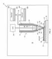
- the additive manufacturing device 24 of FIG. 2 includes a component support 28, one or more material reservoirs 30A and 30B (generally referred to as "30"), at least (or only) one nozzle 32, and at least (or only) one laser 34.
- the additive manufacturing device 24 of FIG. 2 also includes a material regulation device 36.
- the component support 28 is located within an internal build chamber 38 of the additive manufacturing device 24. This component support 28 is configured to support the component 22 within the build chamber 38.
- the component 22, for example, may be placed on top of the component support 28.
- the component 22 may also or alternatively be mounted to the component support 28 via a fixture, which fixture may arrange the component 22 in a fixed position and/or in a known spatial orientation within the build chamber 38.
- the first material reservoir 30A is configured to store a quantity of first braze powder 40A formed from first braze material. This first material reservoir 30A is also configured to supply the first braze powder 40A to the nozzle 32 (e.g., through the material regulation device 36) during select additive manufacturing device operations. Examples of the first material reservoir 30A include, but are not limited to, a tank, a hopper and a bin.
- the second material reservoir 30B is configured to store a quantity of second braze powder 40B formed from second braze material. This second material reservoir 30B is also configured to supply the second braze powder 40B to the nozzle 32 (e.g., through the material regulation device 36) during select additive manufacturing device operations. Examples of the second material reservoir 30B include, but are not limited to, a tank, a hopper and a bin.
- the material regulation device 36 is fluidly coupled with and between the material reservoirs 30 and the nozzle 32.
- the material regulation device 36 is configured to selectively direct the first braze powder 40A from the first material reservoir 30A to the nozzle 32 during a first mode.
- the material regulation device 36 is configured to selectively direct the second braze powder 40B from the second material reservoir 30B to the nozzle 32 during a second mode.
- the material regulation device 36 may also (or may not) be configured to selectively direct one or more combinations of the first braze powder 40A from the first material reservoir 30A and the second braze powder 40B from the second material reservoir 30B to the nozzle 32 during a third mode.
- Examples of the material regulation device 36 include, but are not limited to, a valve or valves, a pump or pumps, a powder wheel or wheels, an auger or augers, and a powder metering wheel or wheels.
- the nozzle 32 is configured to deliver the first braze powder 40A received from the first material reservoir 30A, the second braze powder 40B received from the second material reservoir 30B or a combination of the first braze powder 40A and the second braze powder 40B to a substrate 42 of the component 22 during additive manufacturing device operation. More particularly, the nozzle 32 is configured to direct a (e.g., annular, conical) stream 44 of the braze powder 40A and/or 40B (generally referred to as "40") toward (e.g., to) a surface 46 of the substrate 42.
- the nozzle 32 of FIG. 2 for example, includes a tubular inner sidewall 48 and a tubular outer sidewall 50.
- the outer sidewall 50 extends axially along and circumscribes the inner sidewall 48 so as to form a passage 52 (e.g., an annulus) between the inner sidewall 48 and the outer sidewall 50.
- This passage 52 is fluidly coupled with outlets from the material reservoirs 30 through the material flow regulator 36, and the passage 52 extends axially within the nozzle 32 to a (e.g., annular) nozzle orifice 54.
- a distal end portion of the nozzle 32 and its inner sidewall 48 and its outer sidewall 50 may radially taper inwards as the nozzle 32 extends axially toward (e.g., to) the nozzle orifice 54.
- the nozzle 32 may focus the braze powder 40 to, around or about a target point 56 on, slightly above or slightly below the substrate surface 46.
- the nozzle 32 may be configured to deliver the braze powder 40 through an internal bore rather than an annulus.
- the laser 34 is configured to generate a laser beam 58 for sintering the braze powder 40 delivered by the nozzle 32 together and to the substrate 42.
- sintering may describe a process for coalescing powder particles together into a (e.g., porous) mass by heating without (e.g., partial or complete) liquification of the powder. This is in contrast to, for example, a powder laser welding process where powder is melted to a liquid state (e.g., in a melt pool) by a laser beam and then solidified as a solid mass.
- the laser beam 58 of FIG. 2 is configured to direct the laser beam 58 to or about the target point 56, where the laser beam 58 may be incident with and is operable to heat up the braze powder 40 for sintering.
- the laser beam 58 of FIG. 2 is directed through an (e.g., central) internal bore 60 of the nozzle 32, which internal nozzle bore 60 may be formed by the inner sidewall 48.
- the laser 34 may be configured to direct the laser beam 58 outside of the nozzle 32 or along another path through the nozzle 32.
- the furnace 26 is configured to receive the substrate 42 with the sintered first braze material 62A and/or the sintered second braze material 62B (generally referred to as "62") within an internal treatment chamber 64 of the furnace 26.
- the furnace 26 is further configured to subject the substrate 42 and the sintered braze material(s) 62 to a heat cycle, for example under vacuum and/or in a partial pressure inert gas (e.g., argon (Ar) gas) environment.
- a partial pressure inert gas e.g., argon (Ar) gas
- An example of the furnace 26 is a vacuum furnace.
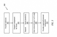
- FIG. 3 is a flow diagram of an exemplary method 300 for manufacturing (e.g., repairing or forming) the component 22.
- the manufacturing method 300 is described with respect to the manufacturing system 20 and repairing the component 22.
- the manufacturing method 300 is not limited to any particular manufacturing types or configurations.
- some or all of the method steps may alternatively be performed to form a new component.
- the substrate 42 is provided.
- this substrate 42 is described as part of a damaged component.
- the component 22 of FIG. 4 includes at least one void 66 such as, but not limited to, a crack, a fracture, a slice, a gouge, a dimple, etc.
- This void 66 projects partially into the component 22 and its substrate 42 from an exterior of the component 22.
- the component 22 of FIG. 4 also include a wear region 68 where a portion of the component 22 and its substrate 42 has been worn away due to, for example, erosion, rubbing and/or otherwise.
- the component 22 may include multiple voids 66, multiple wear regions 68, the void(s) 66 without any wear region, the wear region(s) 68 without any void, and/or one or more other substrate defects.
- the component 22 is prepared for the braze powder.
- a coating 70 (see FIG. 4 ) over at least a portion or an entirety of the substrate 42, for example, may be removed to expose the underlying substrate 42 and its substrate surface 46.
- the coating 70 may be removed using various techniques such as, but not limited to, chemical stripping, abrasive blasting, waterjet blasting and/or machining.
- the substrate surface 46 may also be prepared (e.g., treated) for braze powder deposition.
- Examples of such surface preparation may include, but are not limited to: fluoride ion cleaning (FIC); reverse electroplating, electroplating to introduce a more wettable interface, such as nickel (Ni); nickel honing (e.g., nicroblasting); acid etching; and/or wet abrasive honing.
- Fluoride ion cleaning (FIC) may be particularly useful for removing oxides from deep within tips of narrow cracks, which may facilitate subsequent deep penetration of braze into the cracks for (e.g., complete) healing of the cracks.
- the first braze powder and/or the second braze powder are selectively deposited with the substrate 42 using the additive manufacturing device 24.
- the first braze powder 40A may be deposited with the substrate 42 to repair a first type of substrate defect such as, but not limited to, the void 66 in the substrate 42 of FIG. 6 .
- the second braze powder 40B may be deposited with the substrate 42 to repair a second type of substrate defect (different than the first type of substrate defect) such as, but not limited to, the wear region 68 of FIG. 7 .
- the first braze powder 40A may be provided (e.g., selected, formulated, etc.) for increased wettability, flowability and/or capillary penetration.
- the first braze powder may thereby be particularly suited for entering and filling voids; e.g., see FIG. 6 .
- the second braze powder 40B may be provided (e.g., selected, formulated, etc.) for improved dimensional repair of the surface due to lower wettability and flowability.
- the second braze powder may thereby be particularly suited for forming claddings; e.g., see FIG. 7 .
- the first braze powder 40A and the second braze powder 40B may be mixed together in some proportion to provide a combined braze powder with intermediate braze properties.
- the first braze powder 40A may include a mixture of metal alloy powder (e.g., substrate powder) and braze material powder.
- the metal alloy powder may be selected to have a relatively high melting point and common (the same) or similar material properties as the substrate 42.
- the metal alloy powder for example, may be made from a common (or a similar) material as the underlying substrate 42; e.g., an aluminum (Al) superalloy, a nickel (Ni) superalloy, a titanium (Ti) superalloy, etc.
- the braze material powder on the other hand, may be selected to have a relatively low melting point, which is lower than the melting point of the metal alloy powder.
- the braze material powder may include a common or similar base element as the substrate 42 and/or the metal alloy powder (e.g., aluminum (Al), nickel (Ni) or titanium (Ti)) without the super alloying elements.
- the brazing powder may also include boron (B), silicon (Si) and/or other melting point suppressants which may help facilitate melting and diffusion of the metal alloy powder with the substrate 42.
- B boron
- Si silicon
- the present disclosure is not limited to the foregoing exemplary braze materials.
- the second braze powder 40B may include a mixture of the metal alloy powder (e.g., substrate powder) and the braze material powder.
- a ratio of the metal alloy powder to the braze material powder in the second braze powder 40B may be greater than a ratio of the metal alloy powder to the braze material powder in the first braze powder 40A.
- the second braze powder 40B may include lower proportions of the metal alloy powder relative to the braze material powder (e.g., 30/70).
- the first braze powder 40A may include higher proportions of the metal alloy powder relative to the braze material powder (e.g., 60/40).
- the present disclosure is not limited to the foregoing exemplary braze powder makeups.
- one or more or all of the constituent materials in the first braze powder may be different that one or more or all of the constituent materials in the second braze powder.
- the additive manufacturing device 24 of FIG. 2 may dispose the respective braze powder 40 onto the substrate 42 at or about the target point 56.
- the laser 34 may concurrently sinter this respective braze powder 40 at the target point 56 together and/or to the underlying substrate 42.
- the additive manufacturing device 24 may be positioned and operated to provide the sintered first braze material 62A within the void 66; e.g., to partially or completely fill the void 66. Referring to FIG.
- the additive manufacturing device 24 may be positioned and operated to provide a cladding (e.g., a layer or multiple layers) of the sintered second braze material 62B over the wear region 68; e.g., to build back worn away substrate material.
- the additive manufacturing device 24 may also or alternatively be positioned and operated to provide a cladding (e.g., a layer or multiple layers) of the sintered second braze material 62B over the sintered first braze material 62A and/or one or more other (e.g., adjacent) regions of the substrate 42.
- the additive manufacturing device 24 may selectively deposit the first braze powder and/or the second braze powder over the substrate 42 such that (e.g., only) areas which need repair (and optionally areas adjacent and/or surrounding those areas) are filled with the sintered first braze material 62A and/or coated with the sintered second braze material 62B.
- the first braze powder and/or the second braze powder may be deposited over an entirety of the substrate 42 where excess material may later be removed.
- the first braze powder and/or the second braze powder may be deposited (e.g., built up) as one or more layers during the step 306.
- the substrate 42 and the sintered braze material(s) 62 are heated.
- the substrate 42 with the sintered braze material(s) 62 may be arranged within the treatment chamber 64 of the furnace 26 of FIG. 1 .
- the furnace 26 may subject the substrate 42 with the sintered braze material(s) 62 to a heat cycle. More particularly, the substrate 42 with the sintered braze material(s) 62 may be heated to an elevated temperature within a partial pressure inert gas environment. The elevated temperature is selected such that the sintered braze material(s) 62 melts, wets and flows into defects of the substrate 42 by capillary action.
- a relatively lower temperature may be selected and held in the same heat cycle for a duration.
- This sustained temperature may facilitate diffusion of the melting point suppressant material.
- This diffusion of the melting point suppressant material may facilitate athermal solidification, resulting in a braze diffusion bond of the sintered material to the substrate 42.
- the athermal solidification may describe solidification of the melted sintered braze material under, for example, a constant temperature.
- the diffusion duration may be between four (4) hours and twelve (12) hours, but may be much shorter or longer depending on materials being diffusion brazed and/or desired material properties.
- This elevated temperature is less than a melting point temperature of the substrate material.
- the elevated temperature for the braze melt may be between 1,500°F (816°C) and 2,500°F (1371°C).
- the elevated temperature for the braze diffusion for example, may be between 1,000°F (538°C) and 2,400°F (1316°C).
- the inert gas environment may have a vacuum pressure range between, for example, 0.5 microns and 0.1 microns.
- the present disclosure is not limited to the foregoing exemplary heat cycle parameters, and the foregoing heat cycle parameters may vary depending upon the specific material composition of the substrate 42 and the braze material, dimensions (e.g., thickness) of the sintered braze material(s) 62, etc.
- first braze filler material 72A (e.g., the melted and diffusion bonded first braze material) of FIG. 8 may heal the void 66.
- the first braze filler material 72A may partially or completely fill the void 66.
- the second braze filler material 72B may provide a cladding over the substrate 42 to restore a dimensional parameter of and/or reinforce the wear region 68 and/or other regions.
- Second braze filler material72B (e.g., the melted and diffusion bonded second braze material), for example, may buildup the wear region 68 back to or above a dimensional parameter specified therefor by a design specification or a repair specification for the component 22.
- the substrate 42 with the braze filler material(s) 72A and 72B may be processed (e.g., post-braze processed) to provide a repaired / restored component.
- Excess braze filler material(s) may be removed, the substrate material and/or the braze filler material(s) may be finished (e.g., sanded, polished, etc.), and/or one or more coatings 74 (e.g., bond coating(s), environmental coating(s), thermal barrier coating(s), etc.) may be applied to the substrate 42 and/or the braze filler material(s) 72.
- the respective braze powder 40 and the laser beam 58 may be concurrently directed to the common target point 56 for the braze powder deposition. In other embodiments, however, the laser beam 58 may alternatively be directed to a different target point than the respective braze powder 40.
- the laser beam target point for example, may alternatively be spaced from and follow the braze powder target point.
- the respective braze powder 40 may be sintered using the laser beam 58.
- the present disclosure is not limited to use of such an exemplary energy beam.
- the respective braze powder may alternatively be sintered using an electron beam provided by an electron beam source.
- multiple energy beams e.g., laser beams and/or electron beams
- multiple nozzles 32 may be used to delivery the braze powders 40A and 40B.
- a component manufactured using a typical additive laser deposition welding process may be subject to: internal stresses thermally induced by relatively high welding temperatures (e.g., temperatures high enough to melt the substrate material); thermally induced distortion and/or warping; and/or reduction in material density caused by, for example, dendritic voids.
- sintering the braze powder(s) 40A and/or 40B with the substrate 42 and then diffusion bonding the sintered braze material(s) with the substrate 42 as described above subjects the substrate 42 to relatively low processing temperatures, compared to welding temperatures.
- the manufacturing methods of the present disclosure may thereby reduce or eliminate: thermally induced stresses; thermally induced distortion and/or warping; and/or reduction in material density associated with additive laser deposition welding techniques.
- the above laser braze cladding technique may also be paired with adaptive processing to reduce material consumption and/or require less post processing (e.g., machining, finishing, etc.) compared to traditional manual brazing techniques.
Landscapes
- Engineering & Computer Science (AREA)
- Mechanical Engineering (AREA)
- Chemical & Material Sciences (AREA)
- Manufacturing & Machinery (AREA)
- Materials Engineering (AREA)
- Physics & Mathematics (AREA)
- General Engineering & Computer Science (AREA)
- Thermal Sciences (AREA)
- Optics & Photonics (AREA)
- Powder Metallurgy (AREA)
Abstract
Description
- This disclosure relates generally to manufacturing a component using additive manufacturing.
- Defects in a component may be repaired using braze filler material or weld filler. Various processes are known in the art for applying braze filler material and for welding filler material to a component. While these known processes have various advantages, there is still room in the art for improvement. In particular, there is a need in the art for repair processes which can reduce material waste and/or decrease formation of secondary (process related) defects in a substrate of the component.
- According to an aspect of the present disclosure, a method is provided during which first braze powder is deposited with a substrate. The first braze powder is sintered to the substrate during the depositing of the first braze powder to provide the substrate with sintered first braze material. Second braze powder is deposited with the substrate. The second braze powder is different than the first braze powder. The second braze powder is sintered to the substrate during the depositing of the second braze powder to provide the substrate with sintered second braze material. The sintered first braze material and the sintered second braze material are heated to melt the sintered first braze material and the sintered second braze material and to diffusion bond the sintered first braze material and the sintered second braze material to the substrate.
- According to another aspect of the present disclosure, another method is provided during which an additive manufacturing device is provided. The additive manufacturing device includes a first reservoir and a second reservoir. The first reservoir contains a first braze powder. The second reservoir contains a second braze powder that is different than the first braze powder. The first braze powder is deposited with a substrate using the additive manufacturing device. The first braze powder is sintered to the substrate during the depositing of the first braze powder to provide the substrate with a sintered first braze material. The second braze powder is deposited with the substrate using the additive manufacturing device. The second braze powder is sintered to the substrate during the depositing of the second braze powder to provide the substrate with a sintered second braze material.
- According to still another aspect of the present disclosure, a system is provided for repairing a component that includes a substrate. This system includes an additive manufacturing device and a furnace. The additive manufacturing device includes a first reservoir, a second reservoir and an energy beam source. The additive manufacturing device is configured to direct a first braze powder from the first reservoir onto the substrate and sinter the first braze powder to the substrate using an energy beam generated by the energy beam source to provide a sintered first braze material. The additive manufacturing device is also configured to direct a second braze powder from the second reservoir onto the substrate and sinter the second braze powder to the substrate using the energy beam generated by the energy beam source to provide a sintered second braze material. The furnace is configured to receive the substrate and melt the sintered first braze material and the sinter second braze material to facilitate diffusion bonding of the sintered first braze material and the sintered second braze material to the substrate.
- The following optional features may be applied to any of the above aspects:
The method may also include heating the sintered first braze material and the sintered second braze material in a vacuum furnace to melt the sintered first braze material and the sintered second braze material and to diffusion bond the sintered first braze material and the sintered second braze material to the substrate. - The additive manufacturing device may also include a nozzle. The first braze powder may be directed from the first reservoir, through the nozzle, to the substrate during the depositing of the first braze powder. The second braze powder may be directed from the second reservoir, through the nozzle, to the substrate during the depositing of the second braze powder.
- The sintered first braze material may fill a void in the substrate. The sintered second braze material may form a cladding on the substrate.
- The first braze powder may be deposited with the substrate to fill a void in the substrate. The second braze powder may be deposited with the substrate to form a cladding on the substrate.
- The first braze powder may be deposited with the substrate to repair a first type of defect of the substrate. The second braze powder may be deposited with the substrate to repair a second type of defect of the substrate that is different than the first type of defect.
- The first braze powder may include metal alloy powder and braze material powder with a lower melting point than the metal alloy powder.
- The first braze powder may have a first ratio of the metal alloy powder to the braze material powder. The second braze powder may include the metal alloy powder and the braze material powder. The second braze powder may have a second ratio of the metal alloy powder to the braze material powder. The second ratio may be different than the first ratio.
- The first braze powder may be deposited with the substrate to fill a void in the substrate. The second braze powder may be deposited with the substrate to form a cladding on the substrate. The second ratio may be greater than the first ratio.
- The metal alloy powder and the substrate may be or include a common metal alloy.
- The first braze powder and the second braze powder may be deposited with the substrate using an additive manufacturing device.
- The depositing of the first braze powder may include: directing the first braze powder towards the substrate through a nozzle; and sintering the first braze powder using a laser beam.
- The depositing of the second braze powder may include: directing the second braze powder towards the substrate through the nozzle; and sintering the second braze powder using the laser beam.
- The method may also include: selectively directing the first braze powder from a first reservoir to the nozzle during the depositing of the first braze powder; and selectively directing the second braze powder from a second reservoir to the nozzle during the depositing of the second braze powder.
- The laser beam may be directed towards the substrate through an inner bore of the nozzle.
- A laser beam may sinter the first braze powder to the substrate as the first braze powder is deposited with the substrate. The laser beam may sinter the second braze powder to the substrate as the second braze powder is deposited with the substrate.
- The heating of the sintered first braze material and the sintered second braze material may be performed in a vacuum furnace subsequent to the depositing of the first braze powder and the second braze powder.
- The substrate may be part of a stationary component of a gas turbine engine.
- The present disclosure may include any one or more of the individual features disclosed above and/or below alone or in any combination thereof.
- The foregoing features and the operation of the invention will become more apparent in light of the following description and the accompanying drawings.
-
-
FIG. 1 is a schematic illustration of a system for manufacturing a component. -
FIG. 2 is a schematic illustration of an additive manufacturing device. -
FIG. 3 is a flow diagram of a method for manufacturing the component. -
FIGS. 4-9 are partial sectional illustrations of the component during various steps of the manufacturing method. - The present disclosure includes systems and methods for manufacturing a component. Herein, the term "manufacturing" may describe a process for forming the component; e.g., creating a brand new component. The term "manufacturing" may also or alternatively describe a process for repairing the component; e.g., restoring one or more features of a previously formed component to brand new condition, similar to brand new condition or better than brand new condition. The component, for example, may be repaired to fix one or more defects (e.g., cracks, wear and/or other damage) imparted during previous use of the component. The component may also or alternatively be repaired to fix one or more defects imparted during the initial formation of the component. For ease of description, however, the manufacturing systems and methods may be described below with respect to repairing the component.
- The component may be any stationary component within a hot section of the gas turbine engine; e.g., a combustor section, a turbine section or an exhaust section. Examples of the stationary component include, but are not limited to, a vane, a platform, a gas path wall, a liner and a shroud. The present disclosure, however, is not limited to stationary component applications. The engine component, for example, may alternatively be a rotor blade; e.g., a turbine blade. The present disclosure is also not limited to hot section engine components. For ease of description, however, the manufacturing systems and methods may be described below with respect to repairing a gas turbine engine component such as a turbine vane or other stators within the turbine section.
- The component may be included in various gas turbine engines. The component, for example, may be included in a geared gas turbine engine where a gear train connects one or more shafts to one or more rotors in a fan section, a compressor section and/or any other engine section. Alternatively, the component may be included in a direct-drive gas turbine engine configured without a gear train. The component may be included in a gas turbine engine configured with a single spool, with two spools, or with more than two spools. The gas turbine engine may be configured as a turbofan engine, a turbojet engine, a turboprop engine, a turboshaft engine, a propfan engine, a pusher fan engine or any other type of gas turbine engine. The gas turbine engine may alternatively be configured as an auxiliary power unit (APU) or an industrial gas turbine engine. The present disclosure therefore is not limited to any particular types or configurations of gas turbine engines. Furthermore, it is contemplated the manufacturing systems and methods of the present disclosure may alternatively be used to manufacture component(s) for non-gas turbine engine applications; e.g., for reciprocating piston internal combustion engine applications, for rotary internal combustion engine applications, etc.
-
FIG. 1 schematically illustrates anexemplary system 20 for manufacturing (e.g., repairing or forming) thecomponent 22. Thismanufacturing system 20 includes an additive manufacturing device 24 (e.g., a three-dimensional (3D) printer) and afurnace 26. - Referring to
FIG. 2 , theadditive manufacturing device 24 may be configured as a laser material deposition device. More particularly, theadditive manufacturing device 24 may be configured as a direct laser braze cladding (DLBC) device. Theadditive manufacturing device 24 ofFIG. 2 , for example, includes acomponent support 28, one ormore material reservoirs nozzle 32, and at least (or only) onelaser 34. Theadditive manufacturing device 24 ofFIG. 2 also includes amaterial regulation device 36. - The
component support 28 is located within aninternal build chamber 38 of theadditive manufacturing device 24. Thiscomponent support 28 is configured to support thecomponent 22 within thebuild chamber 38. Thecomponent 22, for example, may be placed on top of thecomponent support 28. Thecomponent 22 may also or alternatively be mounted to thecomponent support 28 via a fixture, which fixture may arrange thecomponent 22 in a fixed position and/or in a known spatial orientation within thebuild chamber 38. - The
first material reservoir 30A is configured to store a quantity offirst braze powder 40A formed from first braze material. Thisfirst material reservoir 30A is also configured to supply thefirst braze powder 40A to the nozzle 32 (e.g., through the material regulation device 36) during select additive manufacturing device operations. Examples of thefirst material reservoir 30A include, but are not limited to, a tank, a hopper and a bin. - The
second material reservoir 30B is configured to store a quantity ofsecond braze powder 40B formed from second braze material. Thissecond material reservoir 30B is also configured to supply thesecond braze powder 40B to the nozzle 32 (e.g., through the material regulation device 36) during select additive manufacturing device operations. Examples of thesecond material reservoir 30B include, but are not limited to, a tank, a hopper and a bin. - The
material regulation device 36 is fluidly coupled with and between the material reservoirs 30 and thenozzle 32. Thematerial regulation device 36 is configured to selectively direct thefirst braze powder 40A from thefirst material reservoir 30A to thenozzle 32 during a first mode. Thematerial regulation device 36 is configured to selectively direct thesecond braze powder 40B from thesecond material reservoir 30B to thenozzle 32 during a second mode. Thematerial regulation device 36 may also (or may not) be configured to selectively direct one or more combinations of thefirst braze powder 40A from thefirst material reservoir 30A and thesecond braze powder 40B from thesecond material reservoir 30B to thenozzle 32 during a third mode. Examples of thematerial regulation device 36 include, but are not limited to, a valve or valves, a pump or pumps, a powder wheel or wheels, an auger or augers, and a powder metering wheel or wheels. - The
nozzle 32 is configured to deliver thefirst braze powder 40A received from thefirst material reservoir 30A, thesecond braze powder 40B received from thesecond material reservoir 30B or a combination of thefirst braze powder 40A and thesecond braze powder 40B to asubstrate 42 of thecomponent 22 during additive manufacturing device operation. More particularly, thenozzle 32 is configured to direct a (e.g., annular, conical)stream 44 of thebraze powder 40A and/or 40B (generally referred to as "40") toward (e.g., to) asurface 46 of thesubstrate 42. Thenozzle 32 ofFIG. 2 , for example, includes a tubularinner sidewall 48 and a tubularouter sidewall 50. Theouter sidewall 50 extends axially along and circumscribes theinner sidewall 48 so as to form a passage 52 (e.g., an annulus) between theinner sidewall 48 and theouter sidewall 50. Thispassage 52 is fluidly coupled with outlets from the material reservoirs 30 through thematerial flow regulator 36, and thepassage 52 extends axially within thenozzle 32 to a (e.g., annular)nozzle orifice 54. A distal end portion of thenozzle 32 and itsinner sidewall 48 and itsouter sidewall 50 may radially taper inwards as thenozzle 32 extends axially toward (e.g., to) thenozzle orifice 54. With such an arrangement, thenozzle 32 may focus thebraze powder 40 to, around or about atarget point 56 on, slightly above or slightly below thesubstrate surface 46. However, in alternative embodiments, thenozzle 32 may be configured to deliver thebraze powder 40 through an internal bore rather than an annulus. - The
laser 34 is configured to generate alaser beam 58 for sintering thebraze powder 40 delivered by thenozzle 32 together and to thesubstrate 42. Herein, the term "sintering" may describe a process for coalescing powder particles together into a (e.g., porous) mass by heating without (e.g., partial or complete) liquification of the powder. This is in contrast to, for example, a powder laser welding process where powder is melted to a liquid state (e.g., in a melt pool) by a laser beam and then solidified as a solid mass. Thelaser 34 ofFIG. 2 is configured to direct thelaser beam 58 to or about thetarget point 56, where thelaser beam 58 may be incident with and is operable to heat up thebraze powder 40 for sintering. Thelaser beam 58 ofFIG. 2 is directed through an (e.g., central)internal bore 60 of thenozzle 32, which internal nozzle bore 60 may be formed by theinner sidewall 48. However, in other embodiments, thelaser 34 may be configured to direct thelaser beam 58 outside of thenozzle 32 or along another path through thenozzle 32. - Referring to
FIG. 1 , thefurnace 26 is configured to receive thesubstrate 42 with the sinteredfirst braze material 62A and/or the sinteredsecond braze material 62B (generally referred to as "62") within aninternal treatment chamber 64 of thefurnace 26. Thefurnace 26 is further configured to subject thesubstrate 42 and the sintered braze material(s) 62 to a heat cycle, for example under vacuum and/or in a partial pressure inert gas (e.g., argon (Ar) gas) environment. During this heat cycle, the sintered braze material(s) 62 may melt and diffusion bond to thesubstrate 42. An example of thefurnace 26 is a vacuum furnace. -
FIG. 3 is a flow diagram of anexemplary method 300 for manufacturing (e.g., repairing or forming) thecomponent 22. For ease of description, themanufacturing method 300 is described with respect to themanufacturing system 20 and repairing thecomponent 22. Themanufacturing method 300, however, is not limited to any particular manufacturing types or configurations. Furthermore, some or all of the method steps may alternatively be performed to form a new component. - In
step 302, referring toFIG. 4 , thesubstrate 42 is provided. For ease of description, thissubstrate 42 is described as part of a damaged component. For example, thecomponent 22 ofFIG. 4 includes at least onevoid 66 such as, but not limited to, a crack, a fracture, a slice, a gouge, a dimple, etc. This void 66 projects partially into thecomponent 22 and itssubstrate 42 from an exterior of thecomponent 22. Thecomponent 22 ofFIG. 4 also include awear region 68 where a portion of thecomponent 22 and itssubstrate 42 has been worn away due to, for example, erosion, rubbing and/or otherwise. Of course, in other embodiments, thecomponent 22 may includemultiple voids 66,multiple wear regions 68, the void(s) 66 without any wear region, the wear region(s) 68 without any void, and/or one or more other substrate defects. - In
step 304, referring toFIG. 5 , thecomponent 22 is prepared for the braze powder. A coating 70 (seeFIG. 4 ) over at least a portion or an entirety of thesubstrate 42, for example, may be removed to expose theunderlying substrate 42 and itssubstrate surface 46. Thecoating 70 may be removed using various techniques such as, but not limited to, chemical stripping, abrasive blasting, waterjet blasting and/or machining. Thesubstrate surface 46 may also be prepared (e.g., treated) for braze powder deposition. Examples of such surface preparation may include, but are not limited to: fluoride ion cleaning (FIC); reverse electroplating, electroplating to introduce a more wettable interface, such as nickel (Ni); nickel honing (e.g., nicroblasting); acid etching; and/or wet abrasive honing. Fluoride ion cleaning (FIC) may be particularly useful for removing oxides from deep within tips of narrow cracks, which may facilitate subsequent deep penetration of braze into the cracks for (e.g., complete) healing of the cracks. - In
step 306, referring toFIGS. 2 ,6 and 7 , the first braze powder and/or the second braze powder are selectively deposited with thesubstrate 42 using theadditive manufacturing device 24. Thefirst braze powder 40A, for example, may be deposited with thesubstrate 42 to repair a first type of substrate defect such as, but not limited to, the void 66 in thesubstrate 42 ofFIG. 6 . Thesecond braze powder 40B, by contrast, may be deposited with thesubstrate 42 to repair a second type of substrate defect (different than the first type of substrate defect) such as, but not limited to, thewear region 68 ofFIG. 7 . More particularly, thefirst braze powder 40A may be provided (e.g., selected, formulated, etc.) for increased wettability, flowability and/or capillary penetration. The first braze powder may thereby be particularly suited for entering and filling voids; e.g., seeFIG. 6 . Thesecond braze powder 40B, on the other hand, may be provided (e.g., selected, formulated, etc.) for improved dimensional repair of the surface due to lower wettability and flowability. The second braze powder may thereby be particularly suited for forming claddings; e.g., seeFIG. 7 . Of course, it is contemplated thefirst braze powder 40A and thesecond braze powder 40B may be mixed together in some proportion to provide a combined braze powder with intermediate braze properties. - The
first braze powder 40A may include a mixture of metal alloy powder (e.g., substrate powder) and braze material powder. The metal alloy powder may be selected to have a relatively high melting point and common (the same) or similar material properties as thesubstrate 42. The metal alloy powder, for example, may be made from a common (or a similar) material as the underlyingsubstrate 42; e.g., an aluminum (Al) superalloy, a nickel (Ni) superalloy, a titanium (Ti) superalloy, etc. The braze material powder, on the other hand, may be selected to have a relatively low melting point, which is lower than the melting point of the metal alloy powder. The braze material powder, for example, may include a common or similar base element as thesubstrate 42 and/or the metal alloy powder (e.g., aluminum (Al), nickel (Ni) or titanium (Ti)) without the super alloying elements. The brazing powder may also include boron (B), silicon (Si) and/or other melting point suppressants which may help facilitate melting and diffusion of the metal alloy powder with thesubstrate 42. The present disclosure, however, is not limited to the foregoing exemplary braze materials. - The
second braze powder 40B may include a mixture of the metal alloy powder (e.g., substrate powder) and the braze material powder. A ratio of the metal alloy powder to the braze material powder in thesecond braze powder 40B may be greater than a ratio of the metal alloy powder to the braze material powder in thefirst braze powder 40A. For example, thesecond braze powder 40B may include lower proportions of the metal alloy powder relative to the braze material powder (e.g., 30/70). By contrast, thefirst braze powder 40A may include higher proportions of the metal alloy powder relative to the braze material powder (e.g., 60/40). The present disclosure, however, is not limited to the foregoing exemplary braze powder makeups. For example, in other embodiments, one or more or all of the constituent materials in the first braze powder may be different that one or more or all of the constituent materials in the second braze powder. - During the braze powder deposition, the
additive manufacturing device 24 ofFIG. 2 may dispose therespective braze powder 40 onto thesubstrate 42 at or about thetarget point 56. Thelaser 34 may concurrently sinter thisrespective braze powder 40 at thetarget point 56 together and/or to theunderlying substrate 42. Referring toFIG. 6 , theadditive manufacturing device 24 may be positioned and operated to provide the sinteredfirst braze material 62A within the void 66; e.g., to partially or completely fill the void 66. Referring toFIG. 7 , theadditive manufacturing device 24 may be positioned and operated to provide a cladding (e.g., a layer or multiple layers) of the sinteredsecond braze material 62B over thewear region 68; e.g., to build back worn away substrate material. Theadditive manufacturing device 24 may also or alternatively be positioned and operated to provide a cladding (e.g., a layer or multiple layers) of the sinteredsecond braze material 62B over the sinteredfirst braze material 62A and/or one or more other (e.g., adjacent) regions of thesubstrate 42. - The
additive manufacturing device 24 may selectively deposit the first braze powder and/or the second braze powder over thesubstrate 42 such that (e.g., only) areas which need repair (and optionally areas adjacent and/or surrounding those areas) are filled with the sinteredfirst braze material 62A and/or coated with the sinteredsecond braze material 62B. Of course, in other embodiments, the first braze powder and/or the second braze powder may be deposited over an entirety of thesubstrate 42 where excess material may later be removed. The first braze powder and/or the second braze powder may be deposited (e.g., built up) as one or more layers during thestep 306. - In
step 308, referring toFIG. 8 , thesubstrate 42 and the sintered braze material(s) 62 are heated. Thesubstrate 42 with the sintered braze material(s) 62, for example, may be arranged within thetreatment chamber 64 of thefurnace 26 ofFIG. 1 . Thefurnace 26 may subject thesubstrate 42 with the sintered braze material(s) 62 to a heat cycle. More particularly, thesubstrate 42 with the sintered braze material(s) 62 may be heated to an elevated temperature within a partial pressure inert gas environment. The elevated temperature is selected such that the sintered braze material(s) 62 melts, wets and flows into defects of thesubstrate 42 by capillary action. Once the sintered braze material has melted, a relatively lower temperature may be selected and held in the same heat cycle for a duration. This sustained temperature may facilitate diffusion of the melting point suppressant material. This diffusion of the melting point suppressant material may facilitate athermal solidification, resulting in a braze diffusion bond of the sintered material to thesubstrate 42. The athermal solidification may describe solidification of the melted sintered braze material under, for example, a constant temperature. The diffusion duration may be between four (4) hours and twelve (12) hours, but may be much shorter or longer depending on materials being diffusion brazed and/or desired material properties. This elevated temperature, however, is less than a melting point temperature of the substrate material. The elevated temperature for the braze melt, for example, may be between 1,500°F (816°C) and 2,500°F (1371°C). The elevated temperature for the braze diffusion, for example, may be between 1,000°F (538°C) and 2,400°F (1316°C). The inert gas environment may have a vacuum pressure range between, for example, 0.5 microns and 0.1 microns. The present disclosure, however, is not limited to the foregoing exemplary heat cycle parameters, and the foregoing heat cycle parameters may vary depending upon the specific material composition of thesubstrate 42 and the braze material, dimensions (e.g., thickness) of the sintered braze material(s) 62, etc. - Following the
heating step 308, firstbraze filler material 72A (e.g., the melted and diffusion bonded first braze material) ofFIG. 8 may heal the void 66. The firstbraze filler material 72A, for example, may partially or completely fill the void 66. The secondbraze filler material 72B may provide a cladding over thesubstrate 42 to restore a dimensional parameter of and/or reinforce thewear region 68 and/or other regions. Second braze filler material72B (e.g., the melted and diffusion bonded second braze material), for example, may buildup thewear region 68 back to or above a dimensional parameter specified therefor by a design specification or a repair specification for thecomponent 22. - In
step 310, referring toFIG. 9 , thesubstrate 42 with the braze filler material(s) 72A and 72B (generally referred to as "72") may be processed (e.g., post-braze processed) to provide a repaired / restored component. Excess braze filler material(s), for example, may be removed, the substrate material and/or the braze filler material(s) may be finished (e.g., sanded, polished, etc.), and/or one or more coatings 74 (e.g., bond coating(s), environmental coating(s), thermal barrier coating(s), etc.) may be applied to thesubstrate 42 and/or the braze filler material(s) 72. - In some embodiments, referring to
FIG. 2 , therespective braze powder 40 and thelaser beam 58 may be concurrently directed to thecommon target point 56 for the braze powder deposition. In other embodiments, however, thelaser beam 58 may alternatively be directed to a different target point than therespective braze powder 40. The laser beam target point, for example, may alternatively be spaced from and follow the braze powder target point. - In some embodiments, the
respective braze powder 40 may be sintered using thelaser beam 58. The present disclosure, however, is not limited to use of such an exemplary energy beam. The respective braze powder, for example, may alternatively be sintered using an electron beam provided by an electron beam source. Furthermore, multiple energy beams (e.g., laser beams and/or electron beams) may be used for sintering therespective braze powder 40. In addition or alternatively,multiple nozzles 32 may be used to delivery the braze powders 40A and 40B. - A component manufactured using a typical additive laser deposition welding process may be subject to: internal stresses thermally induced by relatively high welding temperatures (e.g., temperatures high enough to melt the substrate material); thermally induced distortion and/or warping; and/or reduction in material density caused by, for example, dendritic voids. By contrast, sintering the braze powder(s) 40A and/or 40B with the
substrate 42 and then diffusion bonding the sintered braze material(s) with thesubstrate 42 as described above subjects thesubstrate 42 to relatively low processing temperatures, compared to welding temperatures. The manufacturing methods of the present disclosure may thereby reduce or eliminate: thermally induced stresses; thermally induced distortion and/or warping; and/or reduction in material density associated with additive laser deposition welding techniques. The above laser braze cladding technique may also be paired with adaptive processing to reduce material consumption and/or require less post processing (e.g., machining, finishing, etc.) compared to traditional manual brazing techniques. - While various embodiments of the present disclosure have been described, it will be apparent to those of ordinary skill in the art that many more embodiments and implementations are possible within the scope of the disclosure. For example, the present disclosure as described herein includes several aspects and embodiments that include particular features. Although these features may be described individually, it is within the scope of the present disclosure that some or all of these features may be combined with any one of the aspects and remain within the scope of the disclosure. Accordingly, the present disclosure is not to be restricted except in light of the attached claims and their equivalents.
Claims (15)
- A method, comprising:depositing first braze powder (40A) with a substrate (42), the first braze powder (40A) sintered to the substrate (42) during the depositing of the first braze powder (40A) to provide the substrate (42) with sintered first braze material (62A);depositing second braze powder (40B) with the substrate (42), the second braze powder (40B) different than the first braze powder (40A) and the second braze powder (40B) sintered to the substrate (42) during the depositing of the second braze powder (40B) to provide the substrate (42) with sintered second braze material (62B); andheating the sintered first braze material (62A) and the sintered second braze material (62B) to melt the sintered first braze material (62A) and the sintered second braze material (62B) and to diffusion bond the sintered first braze material (62A) and the sintered second braze material to the substrate (62B).
- The method of claim 1, wherein:the first braze powder (40A) is deposited with the substrate (42) to fill a void (66) in the substrate (42); andthe second braze powder (40B) is deposited with the substrate (42) to form a cladding on the substrate (42).
- The method of claim 1 or 2, wherein:the first braze powder (40A) is deposited with the substrate (42) to repair a first type of defect of the substrate (42); andthe second braze powder (40B) is deposited with the substrate (42) to repair a second type of defect of the substrate (42) that is different than the first type of defect.
- The method of claim 1, 2 or 3, wherein the first braze powder (40A) comprises metal alloy powder and braze material powder with a lower melting point than the metal alloy powder, and, optionally, the metal alloy powder and the substrate (42) comprise a common metal alloy.
- The method of claim 4, wherein:the first braze powder (40A) has a first ratio of the metal alloy powder to the braze material powder; andthe second braze powder (40B) comprises the metal alloy powder and the braze material powder, the second braze powder (40B) has a second ratio of the metal alloy powder to the braze material powder, and the second ratio is different than the first ratio, wherein, optionally, the second ratio is greater than the first ratio.
- The method of any preceding claim, wherein the first braze powder (40A) and the second braze powder (40B) are deposited with the substrate (42) using an additive manufacturing device (24).
- The method of claim 6, wherein the depositing of the first braze powder (40A) includes:directing the first braze powder (40A) towards the substrate (42) through a nozzle (32); andsintering the first braze powder (40A) using a laser beam (58), wherein, optionally, the laser beam (58) is directed towards the substrate (42) through an inner bore (60) of the nozzle (32).
- The method of claim 7, wherein the depositing of the second braze powder (40B) includes:directing the second braze powder (40B) towards the substrate (42) through the nozzle (32); andsintering the second braze powder (40B) using the laser beam (58).
- The method of claim 8, further comprising:selectively directing the first braze powder (40A) from a first reservoir (30A) to the nozzle (32) during the depositing of the first braze powder (40A); andselectively directing the second braze powder (40B) from a second reservoir (30B) to the nozzle (32) during the depositing of the second braze powder (40B).
- The method of claim any preceding, wherein:a laser beam (58) sinters the first braze powder (40A) to the substrate (42) as the first braze powder (40A) is deposited with the substrate (42); andthe laser beam (58) sinters the second braze powder (40B) to the substrate (42) as the second braze powder (40B) is deposited with the substrate (42).
- The method of any preceding claim, wherein:the heating of the sintered first braze material (62A) and the sintered second braze material (62B) is performed in a vacuum furnace (26) subsequent to the depositing of the first braze powder (40A) and the second braze powder (40B); and/orthe substrate (42) is part of a stationary component of a gas turbine engine.
- A method, comprising:providing an additive manufacturing device (24) including a first reservoir (30A) and a second reservoir (30B), the first reservoir (30A) containing first braze powder (40A), and the second reservoir (30B) containing second braze powder (40B) that is different than the first braze powder (40A);depositing the first braze powder (40A) with a substrate (42) using the additive manufacturing device (24), wherein the first braze powder (40A) is sintered to the substrate (42) during the depositing of the first braze powder (40A) to provide the substrate (42) with sintered first braze material (62A); anddepositing the second braze powder (40B) with the substrate (42) using the additive manufacturing device (24), wherein the second braze powder (40B) is sintered to the substrate (42) during the depositing of the second braze powder (40B) to provide the substrate (42) with sintered second braze material (62B).
- The method of claim 12, further comprising heating the sintered first braze material (62A) and the sintered second braze material (62B) in a vacuum furnace (26) to melt the sintered first braze material (62A) and the sintered second braze material (62B) and to diffusion bond the sintered first braze material (62A) and the sintered second braze material (62B) to the substrate (42).
- The method of claim 12 or 13, wherein:the additive manufacturing device (24) further includes a nozzle (32), the first braze powder (40A) is directed from the first reservoir (30A), through the nozzle (32), to the substrate (42) during the depositing of the first braze powder (40A), and the second braze powder (40B) is directed from the second reservoir (30B), through the nozzle (32), to the substrate (42) during the depositing of the second braze powder (40B); and/orthe sintered first braze material (62A) fills a void (66) in the substrate (42), and the sintered second braze material (62B) forms a cladding on the substrate (42).
- A system for repairing a component comprising a substrate (42), the system comprising:an additive manufacturing device (24) comprising a first reservoir (30A), a second reservoir (30B) and an energy beam source (34), the additive manufacturing device (24) configured to direct first braze powder (40A) from the first reservoir (30A) onto the substrate (42) and sinter the first braze powder (40A) to the substrate (42) using an energy beam (58) generated by the energy beam source (34) to provide sintered first braze material (62A), and the additive manufacturing device (24) further configured to direct second braze powder (40B) from the second reservoir (30B) onto the substrate (42) and sinter the second braze powder (40B) to the substrate (42) using the energy beam (58) generated by the energy beam source (34) to provide sintered second braze material (62B); anda furnace (26) configured to receive the substrate (42) and melt the sintered first braze material (62A) and the sintered second braze material (62B) to facilitate diffusion bonding of the sintered first braze material (62A) and the sintered second braze material (62B) to the substrate (42).
Applications Claiming Priority (1)
| Application Number | Priority Date | Filing Date | Title |
|---|---|---|---|
| US17/942,072 US12296400B2 (en) | 2022-09-09 | 2022-09-09 | Additively depositing multiple braze materials |
Publications (1)
| Publication Number | Publication Date |
|---|---|
| EP4335571A1 true EP4335571A1 (en) | 2024-03-13 |
Family
ID=88016336
Family Applications (1)
| Application Number | Title | Priority Date | Filing Date |
|---|---|---|---|
| EP23196229.1A Pending EP4335571A1 (en) | 2022-09-09 | 2023-09-08 | Additively depositing multiple braze materials |
Country Status (3)
| Country | Link |
|---|---|
| US (1) | US12296400B2 (en) |
| EP (1) | EP4335571A1 (en) |
| CA (1) | CA3211450A1 (en) |
Families Citing this family (3)
| Publication number | Priority date | Publication date | Assignee | Title |
|---|---|---|---|---|
| US20250135588A1 (en) * | 2023-10-27 | 2025-05-01 | Ge Infrastructure Technology Llc | Braze repair using metal coupon with porous region |
| US12544845B2 (en) * | 2023-10-27 | 2026-02-10 | Ge Infrastructure Technology Llc | Porous metal coupon with braze material infiltration barrier for repairing component, component with same and related method |
| US12605768B2 (en) | 2023-10-27 | 2026-04-21 | Ge Infrastructure Technology Llc | Porous metal coupon with low porosity region for repairing component, component with same and related method |
Citations (6)
| Publication number | Priority date | Publication date | Assignee | Title |
|---|---|---|---|---|
| EP1561536A1 (en) * | 2004-02-03 | 2005-08-10 | Siemens Aktiengesellschaft | Process of brazing repairing of a part having a base material with oriented microstructure |
| EP1685923A1 (en) * | 2005-01-27 | 2006-08-02 | United Technologies Corporation | Repair and reclassification of superalloy components |
| WO2015161980A1 (en) * | 2014-04-23 | 2015-10-29 | Siemens Aktiengesellschaft | Method for producing a component |
| DE102017204507A1 (en) * | 2017-03-17 | 2018-09-20 | Siemens Aktiengesellschaft | Method for closing an opening of a turbine blade |
| US20180281125A1 (en) * | 2015-10-07 | 2018-10-04 | Siemens Aktiengesellschaft | Repairing a part having cracks, and part |
| FR3103401A1 (en) * | 2019-11-22 | 2021-05-28 | Safran Aircraft Engines | Material addition process |
Family Cites Families (28)
| Publication number | Priority date | Publication date | Assignee | Title |
|---|---|---|---|---|
| US20080029500A1 (en) * | 2006-08-01 | 2008-02-07 | United Technologies Corporation | Brazing repairs |
| US8140179B2 (en) | 2007-01-19 | 2012-03-20 | S.E. Huffman Corp. | Method and apparatus for repairing turbine components |
| JP2009025119A (en) | 2007-07-19 | 2009-02-05 | General Electric Co <Ge> | Contour measurement apparatus and operation method |
| US20090026182A1 (en) | 2007-07-27 | 2009-01-29 | Honeywell International, Inc. | In-situ brazing methods for repairing gas turbine engine components |
| US20130316183A1 (en) * | 2011-01-13 | 2013-11-28 | Anand A. Kulkarni, JR. | Localized repair of superalloy component |
| CH704448A1 (en) | 2011-02-03 | 2012-08-15 | Alstom Technology Ltd | A method of repairing or reconditioning of heavily damaged component, in particular from the hot gas area of a gas turbine. |
| ITCO20120040A1 (en) | 2012-09-07 | 2014-03-08 | Nuovo Pignone Srl | METHOD FOR REPAIRING A TURBOMACHINE COMPONENT |
| DE102012221782A1 (en) | 2012-11-28 | 2014-05-28 | Lufthansa Technik Ag | Method and device for repairing an aircraft and / or gas turbine component |
| US9505172B2 (en) | 2012-12-17 | 2016-11-29 | Arcam Ab | Method and apparatus for additive manufacturing |
| US9764517B2 (en) | 2013-01-07 | 2017-09-19 | Bae Systems Plc | Object production using an additive manufacturing process and quality assessment of the object |
| US9174312B2 (en) | 2013-03-12 | 2015-11-03 | Honeywell International Inc. | Methods for the repair of gas turbine engine components using additive manufacturing techniques |
| US20160354842A1 (en) * | 2015-06-07 | 2016-12-08 | General Electric Company | Additive manufacturing methods and hybrid articles using brazeable additive structures |
| US10384285B2 (en) * | 2016-02-26 | 2019-08-20 | Siemens Energy, Inc. | Method of selective laser brazing |
| US10174414B2 (en) | 2017-02-16 | 2019-01-08 | General Electric Company | Manufactured article and method |
| US20180243866A1 (en) * | 2017-02-28 | 2018-08-30 | General Electric Company | Turbine component repair with additive manufacturing |
| US11097350B2 (en) | 2017-07-24 | 2021-08-24 | Raytheon Technologies Corporation | Pre-fusion laser sintering for metal powder stabilization during additive manufacturing |
| EP3450055A1 (en) | 2017-08-30 | 2019-03-06 | Siemens Aktiengesellschaft | Method for additively manufacturing a tip structure on a pre-existing part |
| WO2019177607A1 (en) | 2018-03-15 | 2019-09-19 | Siemens Energy, Inc. | Laser braze wire additive manufacturing of a super solutioned turbine blade component with subzero cooling |
| CN112135705B (en) * | 2018-03-27 | 2022-06-14 | 西门子能源美国公司 | Method and system for additive manufacturing or repair by in situ manufacturing and feeding of a sintering line |
| US11998984B2 (en) | 2018-04-01 | 2024-06-04 | Astrobotic Technology, Inc. | Additively manufactured non-uniform porous materials and components in-situ with fully material, and related methods, systems and computer program product |
| US10814439B2 (en) | 2018-05-31 | 2020-10-27 | General Electric Company | Turbomachine repair using additive manufacturing |
| US11285538B2 (en) | 2019-01-30 | 2022-03-29 | General Electric Company | Tooling assembly and method for aligning components for a powder bed additive manufacturing repair process |
| US11305363B2 (en) * | 2019-02-11 | 2022-04-19 | Rolls-Royce Corporation | Repair of through-hole damage using braze sintered preform |
| FR3096296B1 (en) | 2019-05-23 | 2023-11-24 | Inst De Rech Tech Jules Verne | Additive manufacturing process |
| FR3096297B1 (en) | 2019-05-23 | 2024-01-19 | Inst De Rech Tech Jules Verne | Process for repairing a part during additive manufacturing |
| CN113441725B (en) | 2020-03-27 | 2023-09-22 | 斗山重工业建设有限公司 | Method for repairing turbine blade by using additive manufacturing |
| EP3933527A1 (en) | 2020-07-03 | 2022-01-05 | Siemens Aktiengesellschaft | Method and assembly for repairing a workpiece |
| WO2022159363A1 (en) * | 2021-01-19 | 2022-07-28 | Siemens Energy, Inc. | Superalloy powder mixture for liquid assisted additive manufacturing of a superalloy component |
-
2022
- 2022-09-09 US US17/942,072 patent/US12296400B2/en active Active
-
2023
- 2023-09-07 CA CA3211450A patent/CA3211450A1/en active Pending
- 2023-09-08 EP EP23196229.1A patent/EP4335571A1/en active Pending
Patent Citations (6)
| Publication number | Priority date | Publication date | Assignee | Title |
|---|---|---|---|---|
| EP1561536A1 (en) * | 2004-02-03 | 2005-08-10 | Siemens Aktiengesellschaft | Process of brazing repairing of a part having a base material with oriented microstructure |
| EP1685923A1 (en) * | 2005-01-27 | 2006-08-02 | United Technologies Corporation | Repair and reclassification of superalloy components |
| WO2015161980A1 (en) * | 2014-04-23 | 2015-10-29 | Siemens Aktiengesellschaft | Method for producing a component |
| US20180281125A1 (en) * | 2015-10-07 | 2018-10-04 | Siemens Aktiengesellschaft | Repairing a part having cracks, and part |
| DE102017204507A1 (en) * | 2017-03-17 | 2018-09-20 | Siemens Aktiengesellschaft | Method for closing an opening of a turbine blade |
| FR3103401A1 (en) * | 2019-11-22 | 2021-05-28 | Safran Aircraft Engines | Material addition process |
Also Published As
| Publication number | Publication date |
|---|---|
| US12296400B2 (en) | 2025-05-13 |
| US20240082938A1 (en) | 2024-03-14 |
| CA3211450A1 (en) | 2024-03-09 |
Similar Documents
| Publication | Publication Date | Title |
|---|---|---|
| US12296400B2 (en) | Additively depositing multiple braze materials | |
| JP4301402B2 (en) | How to repair a gas turbine engine stationary shroud using laser cladding | |
| US12251757B2 (en) | Adaptively depositing braze material(s) using CT scan data | |
| US7966707B2 (en) | Method for repairing superalloy components using inserts | |
| EP1759799B1 (en) | Method for forming or remanufacturing a turbine engine component | |
| EP4335574A1 (en) | Adaptively depositing braze material using structured light scan data | |
| EP2317078B1 (en) | Abrasive single-crystal turbine blade | |
| EP1721697B2 (en) | Superalloy repair methods and inserts | |
| US20250345856A1 (en) | Adaptive manufacturing using ct scan data | |
| US20170370221A1 (en) | Methods for repairing a damaged component of an engine | |
| EP4335573A1 (en) | Adaptive manufacturing using structured light data | |
| EP4335569A1 (en) | Additively depositing braze material | |
| EP4424443A1 (en) | Manufacturing component using high and low melt point braze materials | |
| US20240003014A1 (en) | Method and system for thermal spraying braze alloy materials onto a nickel-based component to facilitate high density brazed joint with low discontinuities | |
| EP4414102A1 (en) | Adaptive overhaul using structured light single data set | |
| US20240269748A1 (en) | Adaptive overhaul using ct scan single data set | |
| US20240293868A1 (en) | Adaptive overhaul with two braze material and ct scans |
Legal Events
| Date | Code | Title | Description |
|---|---|---|---|
| PUAI | Public reference made under article 153(3) epc to a published international application that has entered the european phase |
Free format text: ORIGINAL CODE: 0009012 |
|
| STAA | Information on the status of an ep patent application or granted ep patent |
Free format text: STATUS: THE APPLICATION HAS BEEN PUBLISHED |
|
| AK | Designated contracting states |
Kind code of ref document: A1 Designated state(s): AL AT BE BG CH CY CZ DE DK EE ES FI FR GB GR HR HU IE IS IT LI LT LU LV MC ME MK MT NL NO PL PT RO RS SE SI SK SM TR |
|
| STAA | Information on the status of an ep patent application or granted ep patent |
Free format text: STATUS: REQUEST FOR EXAMINATION WAS MADE |
|
| 17P | Request for examination filed |
Effective date: 20240913 |
|
| RBV | Designated contracting states (corrected) |
Designated state(s): AL AT BE BG CH CY CZ DE DK EE ES FI FR GB GR HR HU IE IS IT LI LT LU LV MC ME MK MT NL NO PL PT RO RS SE SI SK SM TR |