EP4335376A1 - Tuning method for collimator, controller, collimator and ct machine - Google Patents
Tuning method for collimator, controller, collimator and ct machine Download PDFInfo
- Publication number
- EP4335376A1 EP4335376A1 EP23195877.8A EP23195877A EP4335376A1 EP 4335376 A1 EP4335376 A1 EP 4335376A1 EP 23195877 A EP23195877 A EP 23195877A EP 4335376 A1 EP4335376 A1 EP 4335376A1
- Authority
- EP
- European Patent Office
- Prior art keywords
- thermal
- displacement
- slot plate
- controller
- scan
- Prior art date
- Legal status (The legal status is an assumption and is not a legal conclusion. Google has not performed a legal analysis and makes no representation as to the accuracy of the status listed.)
- Granted
Links
Images




Classifications
-
- G—PHYSICS
- G01—MEASURING; TESTING
- G01T—MEASUREMENT OF NUCLEAR OR X-RADIATION
- G01T1/00—Measuring X-radiation, gamma radiation, corpuscular radiation, or cosmic radiation
- G01T1/29—Measurement performed on radiation beams, e.g. position or section of the beam; Measurement of spatial distribution of radiation
- G01T1/2914—Measurement of spatial distribution of radiation
- G01T1/2921—Static instruments for imaging the distribution of radioactivity in one or two dimensions; Radio-isotope cameras
- G01T1/295—Static instruments for imaging the distribution of radioactivity in one or two dimensions; Radio-isotope cameras using coded aperture devices, e.g. Fresnel zone plates
-
- A—HUMAN NECESSITIES
- A61—MEDICAL OR VETERINARY SCIENCE; HYGIENE
- A61B—DIAGNOSIS; SURGERY; IDENTIFICATION
- A61B6/00—Apparatus or devices for radiation diagnosis; Apparatus or devices for radiation diagnosis combined with radiation therapy equipment
- A61B6/06—Diaphragms
-
- A—HUMAN NECESSITIES
- A61—MEDICAL OR VETERINARY SCIENCE; HYGIENE
- A61B—DIAGNOSIS; SURGERY; IDENTIFICATION
- A61B6/00—Apparatus or devices for radiation diagnosis; Apparatus or devices for radiation diagnosis combined with radiation therapy equipment
- A61B6/02—Arrangements for diagnosis sequentially in different planes; Stereoscopic radiation diagnosis
- A61B6/03—Computed tomography [CT]
- A61B6/032—Transmission computed tomography [CT]
- A61B6/035—Mechanical aspects of CT
-
- A—HUMAN NECESSITIES
- A61—MEDICAL OR VETERINARY SCIENCE; HYGIENE
- A61B—DIAGNOSIS; SURGERY; IDENTIFICATION
- A61B6/00—Apparatus or devices for radiation diagnosis; Apparatus or devices for radiation diagnosis combined with radiation therapy equipment
- A61B6/02—Arrangements for diagnosis sequentially in different planes; Stereoscopic radiation diagnosis
- A61B6/03—Computed tomography [CT]
- A61B6/032—Transmission computed tomography [CT]
-
- A—HUMAN NECESSITIES
- A61—MEDICAL OR VETERINARY SCIENCE; HYGIENE
- A61B—DIAGNOSIS; SURGERY; IDENTIFICATION
- A61B6/00—Apparatus or devices for radiation diagnosis; Apparatus or devices for radiation diagnosis combined with radiation therapy equipment
- A61B6/40—Arrangements for generating radiation specially adapted for radiation diagnosis
- A61B6/4021—Arrangements for generating radiation specially adapted for radiation diagnosis involving movement of the focal spot
-
- A—HUMAN NECESSITIES
- A61—MEDICAL OR VETERINARY SCIENCE; HYGIENE
- A61B—DIAGNOSIS; SURGERY; IDENTIFICATION
- A61B6/00—Apparatus or devices for radiation diagnosis; Apparatus or devices for radiation diagnosis combined with radiation therapy equipment
- A61B6/44—Constructional features of apparatus for radiation diagnosis
- A61B6/4429—Constructional features of apparatus for radiation diagnosis related to the mounting of source units and detector units
-
- A—HUMAN NECESSITIES
- A61—MEDICAL OR VETERINARY SCIENCE; HYGIENE
- A61B—DIAGNOSIS; SURGERY; IDENTIFICATION
- A61B6/00—Apparatus or devices for radiation diagnosis; Apparatus or devices for radiation diagnosis combined with radiation therapy equipment
- A61B6/52—Devices using data or image processing specially adapted for radiation diagnosis
- A61B6/5258—Devices using data or image processing specially adapted for radiation diagnosis involving detection or reduction of artifacts or noise
-
- G—PHYSICS
- G21—NUCLEAR PHYSICS; NUCLEAR ENGINEERING
- G21K—HANDLING OF PARTICLES OR IONISING RADIATION NOT OTHERWISE PROVIDED FOR; IRRADIATION DEVICES; GAMMA RAY OR X-RAY MICROSCOPES
- G21K1/00—Arrangements for handling particles or ionising radiation, e.g. focusing or moderating
- G21K1/02—Arrangements for handling particles or ionising radiation, e.g. focusing or moderating using diaphragms, collimators
- G21K1/04—Arrangements for handling particles or ionising radiation, e.g. focusing or moderating using diaphragms, collimators using variable diaphragms, shutters, choppers
-
- G—PHYSICS
- G21—NUCLEAR PHYSICS; NUCLEAR ENGINEERING
- G21K—HANDLING OF PARTICLES OR IONISING RADIATION NOT OTHERWISE PROVIDED FOR; IRRADIATION DEVICES; GAMMA RAY OR X-RAY MICROSCOPES
- G21K1/00—Arrangements for handling particles or ionising radiation, e.g. focusing or moderating
- G21K1/02—Arrangements for handling particles or ionising radiation, e.g. focusing or moderating using diaphragms, collimators
- G21K1/04—Arrangements for handling particles or ionising radiation, e.g. focusing or moderating using diaphragms, collimators using variable diaphragms, shutters, choppers
- G21K1/046—Arrangements for handling particles or ionising radiation, e.g. focusing or moderating using diaphragms, collimators using variable diaphragms, shutters, choppers varying the contour of the field, e.g. multileaf collimators
-
- H—ELECTRICITY
- H05—ELECTRIC TECHNIQUES NOT OTHERWISE PROVIDED FOR
- H05G—X-RAY TECHNIQUE
- H05G1/00—X-ray apparatus involving X-ray tubes; Circuits therefor
- H05G1/08—Electrical details
- H05G1/26—Measuring, controlling or protecting
- H05G1/30—Controlling
- H05G1/52—Target size or shape; Direction of electron beam, e.g. in tubes with one anode and more than one cathode
Definitions
- the present invention relates to a tuning method for a collimator of a CT machine, in particular to a tuning method for a collimator of a CT machine, a controller for a collimator, a collimator, and a CT machine.
- CT computed tomography
- instability of focal positions of an X-ray tube may lead to a decrease in image quality and even result in image artifacts.
- Focus shifts are mainly caused by the thermal conditions of an X-ray tube.
- the CT machine comprises an anode plate 10 for generating X-rays.
- the collimator used for the CT machine comprises a slot plate 20 and a controller 40.
- thermal Z-control is the most commonly used to compensate for focus shift.
- real-time data obtained by the detector are used, and the distance to be covered by the slot plate is calculated to ensure that the X-ray remains within an effective area of the scan target 32.
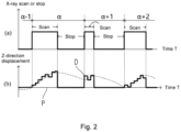
- the Z-direction displacement of segment P represents the Z-direction displacement of the slot plate during a scan, and since no X-ray is emitted during the scan stop period from the closing of the previous scan till the start of the next scan, thermal Z-control cannot be performed. Therefore, when a scan has stopped, the Z-direction displacement of the slot plate is within the scan stop period, and the slot plate has no displacement. When the next scan starts, the actual focus position has substantially deviated from the slot plate position, which results in a decrease in image quality at the beginning of the scan.
- An objective of the present invention is to provide a tuning method for a collimator of a CT machine, which makes it possible to control the displacement of the slot plate during the scan stop stage, thereby improving the image scan quality of the CT machine.
- the present invention provides a collimator for a CT machine.
- the CT machine comprises an anode plate.
- the collimator comprises a slot plate and a controller.
- the tuning method for a collimator of a CT machine which, in each cycle of an X-ray scan operation and a stop, comprises: a detection step of determining whether an X-ray is generated from the anode plate; if an X-ray is detected in the detection step, the controller calculates the Z-direction heating displacement ⁇ z Thermal ⁇ of the slot plate during the current scan, wherein ⁇ indicates the current cycle; the controller drives the slot plate to move by the heating displacement in the Z-direction; if no X-ray is detected in the detection step, the controller calculates the total Z-direction heating displacement z Thermal ⁇ of the slot plate at the end of the current scan; the controller, on the basis of the stop time of the X-ray, calculates the cooling displacement z Thermal ⁇ ′ of the slot plate during the current stop; and the controller
- the slot plate can, on the basis of the total displacement of the previous scan and the stop time, control the displacement of the slot plate during the scan stop stage, thereby minimizing the substantial jitter of the slot plate at the beginning and at the end of a scan, which, in turn, reduces risks of image quality degradation.
- a linear model may be used to estimate the cooling displacement generated at the time when a scan is performed again after cooling following a scan stop.
- f ( ⁇ T ⁇ ) a function of the current stop time
- f ( ⁇ T ⁇ ) ⁇ ⁇ ⁇ T ⁇
- ⁇ is the thermal coefficient of the anode plate.
- the method in each cycle of an X-ray scan operation and a stop, further comprises a step of comparing the cooling displacement z Thermal ⁇ ′ at the current stop with a predetermined cooling position Z min of the slot plate; if the cooling displacement z Thermal ⁇ ′ is not smaller than the predetermined cooling position Z min , the controller drives the slot plate to move by the cooling displacement z Thermal ⁇ ′ ; if the cooling displacement z Thermal ⁇ ′ is smaller than the predetermined cooling position Z min , the controller drives the slot plate to move by the predetermined cooling position Z min .
- the calculated slot plate displacement exceeds a predetermined value, the displacement is a linear change, and when the calculated slot plate displacement is smaller than a predetermined value, the slot plate is displaced by the predetermined value.
- f ( ⁇ T ⁇ ) a function of the current stop time
- f ( ⁇ T ⁇ ) ⁇ ⁇ ⁇ T ⁇
- ⁇ the thermal coefficient of the anode plate
- the method in each cycle of an X-ray scan operation and a stop, further comprises a step of comparing the calculated heating displacement z Thermal ⁇ of the current scanning with a predetermined heating displacement Z max of the slot plate; if the calculated heating displacement z Thermal ⁇ is not greater than the predetermined heating displacement Z max , the controller drives the slot plate to move by the heating displacement z Thermal ⁇ ; if the calculated heating displacement z Thermal ⁇ is greater than the predetermined heating displacement Z max , the controller drives the slot plate to move by the predetermined heating displacement Z m ⁇ x .
- the anode plate is heated, wherein, when the calculated slot plate displacement does not exceed a predetermined value, the displacement changes linearly, and when the calculated slot plate displacement is greater than a predetermined value, the slot plate is displaced by the predetermined value.
- the present invention further provides a controller for a collimator of a CT machine, the controller comprising a control module for executing the above steps.
- the present invention provides a collimator of a CT machine, the collimator comprising a slot plate and a controller as described above.
- the present invention further provides a CT machine, which comprises a collimator as described above.
- a controller, a collimator, and a CT machine provided by the present invention make it possible to, on the basis of the total displacement and stop time of the previous scan, control the displacement of the slot plate during the scan stop stage or simultaneously control the displacement of the slot plate during the scan stage, so that possibility of the slot plate undergoing any substantial jitter when the CT machine performs a scan or stops is minimized, thereby keeping the image quality stable.
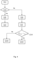
- Fig. 3 is an illustrated embodiment of the tuning method for a collimator of a CT machine.
- the tuning method for a collimator of a CT machine in each cycle of an X-ray scan operation and a stop, comprises the steps of:
- Fig. 4 is an illustrated embodiment of the tuning method for a collimator of a CT machine.
- the tuning method for a collimator of a CT machine in each cycle of an X-ray scan operation and a stop, comprises the steps of:
- Fig. 5 show the changes in the Z-direction displacement over time according to the tuning method for a collimator of a CT machine shown in Fig. 3 .
- part (a) shows the time of an X-ray scan or a stop.
- Part (b) is a graph of the changes in the Z-direction displacement over time.
- the controller calculates the cooling displacement z Thermal ⁇ ′ of the slot plate during the current stop, which is a linear displacement during the stop period ⁇ T.
- Fig. 6 show the changes in the Z-direction displacement over time according to the tuning method for a collimator of a CT machine shown in Fig. 4 .
- Fig. 6 shows the changes in the Z-direction displacement over time according to the tuning method of this embodiment, wherein part (a) shows the time of an X-ray scan or a stop.
- Part (b) is a graph of the changes in the Z-direction displacement over time.
- the heating displacement z Thermal ⁇ is a linear displacement.
- the controller calculates the cooling displacement z Thermal ⁇ ′ of the slot plate at the time of the current stop, which is a linear displacement during the stop period ⁇ T .
- the present invention further provides a controller for a collimator for a CT machine, the controller comprising a control module for executing the above steps.
- the present invention provides a collimator for a CT machine, which comprises a slot plate for a collimator and a controller as described above.
- the present invention further provides a CT machine, which comprises a collimator as described above.
- a controller, a collimator, and a CT machine provided by the present invention make it possible to, on the basis of the total displacement and stop time of the previous scan, control the displacement of the slot plate during the scan stop stage or simultaneously control the displacement of the slot plate during the scan stage, so that possibility of the slot plate undergoing any substantial jitter when the CT machine performs a scan or stops is minimized, thereby keeping the image quality stable.
Landscapes
- Health & Medical Sciences (AREA)
- Life Sciences & Earth Sciences (AREA)
- Engineering & Computer Science (AREA)
- Medical Informatics (AREA)
- Physics & Mathematics (AREA)
- High Energy & Nuclear Physics (AREA)
- Molecular Biology (AREA)
- General Health & Medical Sciences (AREA)
- Biomedical Technology (AREA)
- Public Health (AREA)
- Biophysics (AREA)
- Heart & Thoracic Surgery (AREA)
- Nuclear Medicine, Radiotherapy & Molecular Imaging (AREA)
- Optics & Photonics (AREA)
- Pathology (AREA)
- Radiology & Medical Imaging (AREA)
- Veterinary Medicine (AREA)
- Animal Behavior & Ethology (AREA)
- Surgery (AREA)
- Spectroscopy & Molecular Physics (AREA)
- General Engineering & Computer Science (AREA)
- Pulmonology (AREA)
- Theoretical Computer Science (AREA)
- General Physics & Mathematics (AREA)
- Computer Vision & Pattern Recognition (AREA)
- Toxicology (AREA)
- Apparatus For Radiation Diagnosis (AREA)
Abstract
Description
- The present invention relates to a tuning method for a collimator of a CT machine, in particular to a tuning method for a collimator of a CT machine, a controller for a collimator, a collimator, and a CT machine.
- In computed tomography (CT), instability of focal positions of an X-ray tube may lead to a decrease in image quality and even result in image artifacts. Focus shifts are mainly caused by the thermal conditions of an X-ray tube.
- It is well known that during a scan, the anode plate of the X-ray tube expands when heated, and the focal position moves in one direction along the Z-axis; when the scan has stopped, as the temperature decreases, the anode plate of the X-ray tube will be turned around and move in the opposite direction. This phenomenon is particularly evident in the Z-direction of the tube, and if no corrective measures are taken, an X-ray having passed through the collimator (TCO) will deviate from an effective detector area, which will result in a decrease in image quality. As shown in
Fig. 1 , the CT machine comprises ananode plate 10 for generating X-rays. The collimator used for the CT machine comprises aslot plate 20 and acontroller 40. When the anode plate expands due to heat, thefocal position 12 will move in one direction along the Z-axis to 12', so when the scan target 32 on the scanning table 30 is scanned, the X-ray will have displacements. - To address this problem, thermal Z-control is the most commonly used to compensate for focus shift. With this method, real-time data obtained by the detector are used, and the distance to be covered by the slot plate is calculated to ensure that the X-ray remains within an effective area of the
scan target 32. - As shown in
Fig. 2 , the Z-direction displacement of segment P represents the Z-direction displacement of the slot plate during a scan, and since no X-ray is emitted during the scan stop period from the closing of the previous scan till the start of the next scan, thermal Z-control cannot be performed. Therefore, when a scan has stopped, the Z-direction displacement of the slot plate is within the scan stop period, and the slot plate has no displacement. When the next scan starts, the actual focus position has substantially deviated from the slot plate position, which results in a decrease in image quality at the beginning of the scan. - An objective of the present invention is to provide a tuning method for a collimator of a CT machine, which makes it possible to control the displacement of the slot plate during the scan stop stage, thereby improving the image scan quality of the CT machine.
- The present invention provides a collimator for a CT machine. The CT machine comprises an anode plate. The collimator comprises a slot plate and a controller. The tuning method for a collimator of a CT machine, which, in each cycle of an X-ray scan operation and a stop, comprises: a detection step of determining whether an X-ray is generated from the anode plate; if an X-ray is detected in the detection step, the controller calculates the Z-direction heating displacement


- With the tuning method for a collimator of a CT machine provided by the present invention, by "learning control", the slot plate can, on the basis of the total displacement of the previous scan and the stop time, control the displacement of the slot plate during the scan stop stage, thereby minimizing the substantial jitter of the slot plate at the beginning and at the end of a scan, which, in turn, reduces risks of image quality degradation.
- In an illustrated embodiment of the tuning method for a collimator of a CT machine, the cooling displacement


- In another schematic embodiment of the tuning method for a collimator of a CT machine, f (ΔTα) , a function of the current stop time, is a linear function, namely f (ΔTα) = κ ▪ ΔTα, wherein κ is the thermal coefficient of the anode plate. During the scan stop ΔT, the X-ray tube cools down because no scan is performed. Therefore, the focal position keeps drifting in a direction opposite to a heating direction. Therefore, a linear equation in units of time ΔT is established to estimate the required slot plate position before the next scan.
- In another illustrated embodiment of the tuning method for a collimator of a CT machine, the method, in each cycle of an X-ray scan operation and a stop, further comprises a step of comparing the cooling displacement


- In another illustrated embodiment of the tuning method for a collimator of a CT machine, the total heating displacement


- In another illustrated embodiment of the tuning method for a collimator of a CT machine, the heating displacement


- In another illustrated embodiment of the tuning method for a collimator of a CT machine, f (ΔTα) , a function of the current stop time, is a linear function, namely f (ΔTα) = κ ▪ ΔTα , wherein κ is the thermal coefficient of the anode plate. Therefore, the heating displacement during a scan may change linearly.
- In another illustrated embodiment of the tuning method for a collimator of a CT machine, the method, in each cycle of an X-ray scan operation and a stop, further comprises a step of comparing the calculated heating displacement


- The present invention further provides a controller for a collimator of a CT machine, the controller comprising a control module for executing the above steps.
- The present invention provides a collimator of a CT machine, the collimator comprising a slot plate and a controller as described above.
- The present invention further provides a CT machine, which comprises a collimator as described above.
- A controller, a collimator, and a CT machine provided by the present invention make it possible to, on the basis of the total displacement and stop time of the previous scan, control the displacement of the slot plate during the scan stop stage or simultaneously control the displacement of the slot plate during the scan stage, so that possibility of the slot plate undergoing any substantial jitter when the CT machine performs a scan or stops is minimized, thereby keeping the image quality stable.
- The present invention is explained in detail below in conjunction with the accompanying drawings and particular embodiments.
-
Fig. 1 is a schematic diagram of the Z-direction displacements of the anode plate of a collimator for a CT machine in the prior art. -
Fig. 2 shows the changes in the Z-direction displacement over time according to a method for compensating for the focus shift in the prior art. -
Fig. 3 shows an illustrated embodiment of the tuning method for a collimator of a CT machine according to the present invention. -
Fig. 4 shows an illustrated embodiment of the tuning method for a collimator of a CT machine according to the present invention. -
Fig. 5 show the changes in the Z-direction displacement over time according to the tuning method for a collimator of a CT machine shown inFig. 3 . -
Fig. 6 show the changes in the Z-direction displacement over time according to the tuning method for a collimator of a CT machine shown inFig. 4 . - To enable clearer understanding of the technical features, objectives and effects of the invention, particular embodiments of the present invention are now explained with reference to the accompanying drawings, in which identical labels indicate structurally identical components or components with similar structures but identical functions.
- As used herein, "schematic" means "serving as an instance, example or illustration". No drawing or embodiment described herein as "schematic" should be interpreted as being a more preferred or more advantageous technical solution.
- The various numbers used herein, instead of being strict mathematical and/or geometric limitations, also contain errors that are comprehensible to those skilled in the art and are allowable in manufacture or use.
-
Fig. 3 is an illustrated embodiment of the tuning method for a collimator of a CT machine. As shown inFig. 3 , the tuning method for a collimator of a CT machine, in each cycle of an X-ray scan operation and a stop, comprises the steps of: - S10: a detection step of determining whether an X-ray is generated from the anode plate;
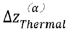
- S20: if an X-ray is detected in the detection step, the controller calculates the Z-direction heating displacement
- S22: the controller drives the slot plate to move by the heating displacement in the Z-direction;
- S30: if no X-rays are detected in the detection step (S10), the controller calculates the total Z-direction heating displacement
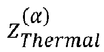
- S32: the controller, on the basis of the stop time of the X-ray, calculates the cooling displacement

- S34: the controller drives the slot plate to move.
-
Fig. 4 is an illustrated embodiment of the tuning method for a collimator of a CT machine. As shown inFig. 4 , the tuning method for a collimator of a CT machine, in each cycle of an X-ray scan operation and a stop, comprises the steps of: - S10: a detection step of determining whether an X-ray is generated from the anode plate;
- S20: if an X-ray is detected in the detection step, the controller calculates the Z-direction heating displacement

- S22: the controller drives the slot plate to move by the heating displacement in the Z-direction;
- S30: if no X-ray is detected in the detection step, the controller calculates the total Z-direction heating displacement


- S32: the controller, on the basis of the stop time of the X-ray, calculates the cooling displacement


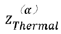

- S341: compare the cooling displacement

- S342: if the cooling displacement


- S344: if the cooling displacement

-
Fig. 5 show the changes in the Z-direction displacement over time according to the tuning method for a collimator of a CT machine shown inFig. 3 . As shown inFig. 5 , part (a) shows the time of an X-ray scan or a stop. Part (b) is a graph of the changes in the Z-direction displacement over time. As shown inFig. 5 , during a scan stop, the controller, on the basis of the X-ray stop time, calculates the cooling displacement
-
Fig. 6 show the changes in the Z-direction displacement over time according to the tuning method for a collimator of a CT machine shown inFig. 4 . In step S30, the heating displacement

Fig. 6 shows the changes in the Z-direction displacement over time according to the tuning method of this embodiment, wherein part (a) shows the time of an X-ray scan or a stop. Part (b) is a graph of the changes in the Z-direction displacement over time. As shown inFig. 5 , during a scan, the heating displacement

- The present invention further provides a controller for a collimator for a CT machine, the controller comprising a control module for executing the above steps.
- The present invention provides a collimator for a CT machine, which comprises a slot plate for a collimator and a controller as described above.
- The present invention further provides a CT machine, which comprises a collimator as described above.
- A controller, a collimator, and a CT machine provided by the present invention make it possible to, on the basis of the total displacement and stop time of the previous scan, control the displacement of the slot plate during the scan stop stage or simultaneously control the displacement of the slot plate during the scan stage, so that possibility of the slot plate undergoing any substantial jitter when the CT machine performs a scan or stops is minimized, thereby keeping the image quality stable.
- It should be understood that although the description herein is based on various embodiments, it is by no means the case that each embodiment contains just one independent technical solution. Such a method of presentation is adopted herein purely for the sake of clarity. Those skilled in the art should consider the description in its entirety. The technical solutions in the various embodiments could also be suitably combined to form other embodiments understandable to those skilled in the art.
- The series of detailed explanations set out above are merely particular explanations of feasible embodiments of the present invention, which are not intended to limit the scope of protection thereof. All equivalent embodiments or changes made without departing from the artistic spirit of the present invention, such as combinations, divisions or repetitions of features, shall be included in the scope of protection of the present invention.
Claims (11)
- A tuning method for a collimator of a CT machine, the CT machine comprising an anode plate (10), the collimator comprising a slot plate (20) and a controller (40), wherein the tuning method, in each cycle of an X-ray scan operation and a stop, comprises:a detection step (S10) of determining whether an X-ray is generated from the anode plate;if an X-ray is detected in the detection step (S10), the controller calculates a Z-direction heating displacement
 the controller drives the slot plate to move by the heating displacement in the Z-direction (S22);
characterized in thatif no X-ray is detected in the detection step (S10), the controller calculates a total Z-direction heating displacement the controller, on the basis of the stop time of the X-ray, calculates a cooling displacement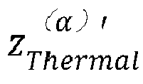
- The tuning method according to claim 1, characterized in that the cooling displacement


- The tuning method according to claim 2, characterized in that f (ΔTα) , the function of the current stop time, is a linear function, namely

- The tuning method according to any one of claims 1-3, characterized in that the tuning method, in each cycle of an X-ray scan operation and a stop, further comprisescomparing the cooling displacement
 if the cooling displacement
 if the cooling displacement
- The tuning method according to any one of claims 1-4, characterized in that the total heating displacement


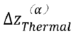

- The tuning method according to claim 5, characterized in that the heating displacement


- The tuning method according to claim 5 or 6, characterized in that the heating displacement
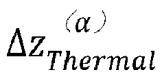

- The tuning method according to claim 7, characterized in that the tuning method, in each cycle of an X-ray scan operation and a stop, further comprisescomparing the calculated heating displacement
 if the calculated heating displacement
 if the calculated heating displacement
- A controller for a collimator of a CT machine, the controller (40) comprising a control module for executing the steps as claimed any one of claims 1-8.
- A collimator of a CT machine, comprising a slot plate (20) and a controller (40) as claimed in claim 9.
- A CT machine, comprising a collimator as claimed in claim 10.
Applications Claiming Priority (1)
| Application Number | Priority Date | Filing Date | Title |
|---|---|---|---|
| CN202211104140.4A CN117679054A (en) | 2022-09-09 | 2022-09-09 | Collimator adjustment method, controller, collimator and CT machine |
Publications (3)
| Publication Number | Publication Date |
|---|---|
| EP4335376A1 true EP4335376A1 (en) | 2024-03-13 |
| EP4335376C0 EP4335376C0 (en) | 2025-02-26 |
| EP4335376B1 EP4335376B1 (en) | 2025-02-26 |
Family
ID=87971949
Family Applications (1)
| Application Number | Title | Priority Date | Filing Date |
|---|---|---|---|
| EP23195877.8A Active EP4335376B1 (en) | 2022-09-09 | 2023-09-07 | Tuning method for collimator, controller, collimator and ct machine |
Country Status (3)
| Country | Link |
|---|---|
| US (1) | US12554027B2 (en) |
| EP (1) | EP4335376B1 (en) |
| CN (1) | CN117679054A (en) |
Citations (3)
| Publication number | Priority date | Publication date | Assignee | Title |
|---|---|---|---|---|
| US4991189A (en) * | 1990-04-16 | 1991-02-05 | General Electric Company | Collimation apparatus for x-ray beam correction |
| WO2011068145A1 (en) * | 2009-12-02 | 2011-06-09 | 株式会社 日立メディコ | X-ray ct device |
| US8331527B2 (en) * | 2008-03-03 | 2012-12-11 | Hitachi Medical Corporation | X-ray CT apparatus and method for correcting X-ray beam position |
Family Cites Families (5)
| Publication number | Priority date | Publication date | Assignee | Title |
|---|---|---|---|---|
| US6256364B1 (en) * | 1998-11-24 | 2001-07-03 | General Electric Company | Methods and apparatus for correcting for x-ray beam movement |
| JP2004016499A (en) * | 2002-06-17 | 2004-01-22 | Ge Medical Systems Global Technology Co Llc | X-ray ct equipment and operation console |
| JP2006051233A (en) * | 2004-08-13 | 2006-02-23 | Ge Medical Systems Global Technology Co Llc | Collimator control method and x-ray ct apparatus |
| JP5697656B2 (en) * | 2010-02-26 | 2015-04-08 | 株式会社日立メディコ | X-ray imaging device |
| US8774351B2 (en) * | 2011-04-05 | 2014-07-08 | Triple Ring Technologies, Inc. | Method and apparatus for advanced X-ray imaging systems |
-
2022
- 2022-09-09 CN CN202211104140.4A patent/CN117679054A/en active Pending
-
2023
- 2023-09-07 EP EP23195877.8A patent/EP4335376B1/en active Active
- 2023-09-08 US US18/243,747 patent/US12554027B2/en active Active
Patent Citations (3)
| Publication number | Priority date | Publication date | Assignee | Title |
|---|---|---|---|---|
| US4991189A (en) * | 1990-04-16 | 1991-02-05 | General Electric Company | Collimation apparatus for x-ray beam correction |
| US8331527B2 (en) * | 2008-03-03 | 2012-12-11 | Hitachi Medical Corporation | X-ray CT apparatus and method for correcting X-ray beam position |
| WO2011068145A1 (en) * | 2009-12-02 | 2011-06-09 | 株式会社 日立メディコ | X-ray ct device |
Also Published As
| Publication number | Publication date |
|---|---|
| CN117679054A (en) | 2024-03-12 |
| US12554027B2 (en) | 2026-02-17 |
| EP4335376C0 (en) | 2025-02-26 |
| EP4335376B1 (en) | 2025-02-26 |
| US20240085579A1 (en) | 2024-03-14 |
Similar Documents
| Publication | Publication Date | Title |
|---|---|---|
| JP5815410B2 (en) | X-ray CT system | |
| US5469429A (en) | X-ray CT apparatus having focal spot position detection means for the X-ray tube and focal spot position adjusting means | |
| US9549712B2 (en) | Method and apparatus for correcting focus of CT device | |
| CN101662987B (en) | X-ray beam Z-axis positioning | |
| CN103140172A (en) | X-ray imaging apparatus and x-ray focus position control method of x-ray imaging apparatus | |
| JP5437991B2 (en) | X-ray CT apparatus and X-ray beam position correction method | |
| JP5697656B2 (en) | X-ray imaging device | |
| WO2011105472A1 (en) | X-ray imaging device | |
| EP4429553B1 (en) | Usage-based wear model and improved lifetime for x-ray devices | |
| US9835837B2 (en) | Method and apparatus for estimating an in-focus position | |
| JP6122796B2 (en) | X-ray thickness gauge | |
| EP4335376B1 (en) | Tuning method for collimator, controller, collimator and ct machine | |
| CN110192888A (en) | Control method, device, computer equipment and the storage medium of tube current | |
| WO2014024881A1 (en) | X-ray photography system | |
| US12628261B2 (en) | Operating a filament of an X-ray tube | |
| JP2004221082A (en) | Method of controlling emissivity of radiation from radiation source | |
| US7366283B2 (en) | Method to control anodic current in an x-ray source | |
| JP5640690B2 (en) | X-ray inspection equipment | |
| JP2004349254A (en) | Method of supplying power to heating element of radiation source and corresponding radiation source | |
| JP6777556B2 (en) | X-ray CT device | |
| US12200850B2 (en) | Active rise and fall time compensation algorithm | |
| CN108956658B (en) | X-ray system and method for calibrating deflection current of X-ray tube | |
| EP4676167A1 (en) | Controlling a high voltage generator for an x-ray source | |
| CN117630061A (en) | X-ray CT device | |
| JP5220995B2 (en) | X-ray irradiation apparatus and X-ray irradiation time control method |
Legal Events
| Date | Code | Title | Description |
|---|---|---|---|
| PUAI | Public reference made under article 153(3) epc to a published international application that has entered the european phase |
Free format text: ORIGINAL CODE: 0009012 |
|
| STAA | Information on the status of an ep patent application or granted ep patent |
Free format text: STATUS: REQUEST FOR EXAMINATION WAS MADE |
|
| 17P | Request for examination filed |
Effective date: 20230907 |
|
| AK | Designated contracting states |
Kind code of ref document: A1 Designated state(s): AL AT BE BG CH CY CZ DE DK EE ES FI FR GB GR HR HU IE IS IT LI LT LU LV MC ME MK MT NL NO PL PT RO RS SE SI SK SM TR |
|
| RBV | Designated contracting states (corrected) |
Designated state(s): AL AT BE BG CH CY CZ DE DK EE ES FI FR GB GR HR HU IE IS IT LI LT LU LV MC ME MK MT NL NO PL PT RO RS SE SI SK SM TR |
|
| GRAP | Despatch of communication of intention to grant a patent |
Free format text: ORIGINAL CODE: EPIDOSNIGR1 |
|
| STAA | Information on the status of an ep patent application or granted ep patent |
Free format text: STATUS: GRANT OF PATENT IS INTENDED |
|
| INTG | Intention to grant announced |
Effective date: 20240925 |
|
| GRAS | Grant fee paid |
Free format text: ORIGINAL CODE: EPIDOSNIGR3 |
|
| GRAA | (expected) grant |
Free format text: ORIGINAL CODE: 0009210 |
|
| STAA | Information on the status of an ep patent application or granted ep patent |
Free format text: STATUS: THE PATENT HAS BEEN GRANTED |
|
| AK | Designated contracting states |
Kind code of ref document: B1 Designated state(s): AL AT BE BG CH CY CZ DE DK EE ES FI FR GB GR HR HU IE IS IT LI LT LU LV MC ME MK MT NL NO PL PT RO RS SE SI SK SM TR |
|
| REG | Reference to a national code |
Ref country code: GB Ref legal event code: FG4D |
|
| REG | Reference to a national code |
Ref country code: CH Ref legal event code: EP |
|
| REG | Reference to a national code |
Ref country code: DE Ref legal event code: R081 Ref document number: 602023002200 Country of ref document: DE Owner name: SIEMENS HEALTHINEERS AG, DE Free format text: FORMER OWNER: ANMELDERANGABEN UNKLAR / UNVOLLSTAENDIG, 80297 MUENCHEN, DE |
|
| REG | Reference to a national code |
Ref country code: DE Ref legal event code: R096 Ref document number: 602023002200 Country of ref document: DE |
|
| REG | Reference to a national code |
Ref country code: IE Ref legal event code: FG4D |
|
| U01 | Request for unitary effect filed |
Effective date: 20250226 |
|
| U07 | Unitary effect registered |
Designated state(s): AT BE BG DE DK EE FI FR IT LT LU LV MT NL PT RO SE SI Effective date: 20250306 |
|
| PG25 | Lapsed in a contracting state [announced via postgrant information from national office to epo] |
Ref country code: RS Free format text: LAPSE BECAUSE OF FAILURE TO SUBMIT A TRANSLATION OF THE DESCRIPTION OR TO PAY THE FEE WITHIN THE PRESCRIBED TIME-LIMIT Effective date: 20250526 |
|
| PG25 | Lapsed in a contracting state [announced via postgrant information from national office to epo] |
Ref country code: PL Free format text: LAPSE BECAUSE OF FAILURE TO SUBMIT A TRANSLATION OF THE DESCRIPTION OR TO PAY THE FEE WITHIN THE PRESCRIBED TIME-LIMIT Effective date: 20250226 |
|
| PG25 | Lapsed in a contracting state [announced via postgrant information from national office to epo] |
Ref country code: ES Free format text: LAPSE BECAUSE OF FAILURE TO SUBMIT A TRANSLATION OF THE DESCRIPTION OR TO PAY THE FEE WITHIN THE PRESCRIBED TIME-LIMIT Effective date: 20250226 |
|
| PG25 | Lapsed in a contracting state [announced via postgrant information from national office to epo] |
Ref country code: NO Free format text: LAPSE BECAUSE OF FAILURE TO SUBMIT A TRANSLATION OF THE DESCRIPTION OR TO PAY THE FEE WITHIN THE PRESCRIBED TIME-LIMIT Effective date: 20250526 Ref country code: IS Free format text: LAPSE BECAUSE OF FAILURE TO SUBMIT A TRANSLATION OF THE DESCRIPTION OR TO PAY THE FEE WITHIN THE PRESCRIBED TIME-LIMIT Effective date: 20250626 |
|
| PG25 | Lapsed in a contracting state [announced via postgrant information from national office to epo] |
Ref country code: HR Free format text: LAPSE BECAUSE OF FAILURE TO SUBMIT A TRANSLATION OF THE DESCRIPTION OR TO PAY THE FEE WITHIN THE PRESCRIBED TIME-LIMIT Effective date: 20250226 |
|
| PG25 | Lapsed in a contracting state [announced via postgrant information from national office to epo] |
Ref country code: GR Free format text: LAPSE BECAUSE OF FAILURE TO SUBMIT A TRANSLATION OF THE DESCRIPTION OR TO PAY THE FEE WITHIN THE PRESCRIBED TIME-LIMIT Effective date: 20250527 |
|
| PG25 | Lapsed in a contracting state [announced via postgrant information from national office to epo] |
Ref country code: SM Free format text: LAPSE BECAUSE OF FAILURE TO SUBMIT A TRANSLATION OF THE DESCRIPTION OR TO PAY THE FEE WITHIN THE PRESCRIBED TIME-LIMIT Effective date: 20250226 |
|
| PG25 | Lapsed in a contracting state [announced via postgrant information from national office to epo] |
Ref country code: CZ Free format text: LAPSE BECAUSE OF FAILURE TO SUBMIT A TRANSLATION OF THE DESCRIPTION OR TO PAY THE FEE WITHIN THE PRESCRIBED TIME-LIMIT Effective date: 20250226 |
|
| PG25 | Lapsed in a contracting state [announced via postgrant information from national office to epo] |
Ref country code: SK Free format text: LAPSE BECAUSE OF FAILURE TO SUBMIT A TRANSLATION OF THE DESCRIPTION OR TO PAY THE FEE WITHIN THE PRESCRIBED TIME-LIMIT Effective date: 20250226 |
|
| U20 | Renewal fee for the european patent with unitary effect paid |
Year of fee payment: 3 Effective date: 20250919 |
|
| PLBE | No opposition filed within time limit |
Free format text: ORIGINAL CODE: 0009261 |
|
| STAA | Information on the status of an ep patent application or granted ep patent |
Free format text: STATUS: NO OPPOSITION FILED WITHIN TIME LIMIT |
|
| 26N | No opposition filed |
Effective date: 20251127 |