EP4334775B1 - Spectacle rod with friction element at ear bend - Google Patents
Spectacle rod with friction element at ear bend Download PDFInfo
- Publication number
- EP4334775B1 EP4334775B1 EP22724421.7A EP22724421A EP4334775B1 EP 4334775 B1 EP4334775 B1 EP 4334775B1 EP 22724421 A EP22724421 A EP 22724421A EP 4334775 B1 EP4334775 B1 EP 4334775B1
- Authority
- EP
- European Patent Office
- Prior art keywords
- metal rod
- rod
- friction element
- spectacle
- transverse
- Prior art date
- Legal status (The legal status is an assumption and is not a legal conclusion. Google has not performed a legal analysis and makes no representation as to the accuracy of the status listed.)
- Active
Links
Images


Classifications
-
- G—PHYSICS
- G02—OPTICS
- G02C—SPECTACLES; SUNGLASSES OR GOGGLES INSOFAR AS THEY HAVE THE SAME FEATURES AS SPECTACLES; CONTACT LENSES
- G02C5/00—Constructions of non-optical parts
- G02C5/14—Side-members
- G02C5/143—Side-members having special ear pieces
-
- G—PHYSICS
- G02—OPTICS
- G02C—SPECTACLES; SUNGLASSES OR GOGGLES INSOFAR AS THEY HAVE THE SAME FEATURES AS SPECTACLES; CONTACT LENSES
- G02C5/00—Constructions of non-optical parts
- G02C5/14—Side-members
- G02C5/16—Side-members resilient or with resilient parts
-
- G—PHYSICS
- G02—OPTICS
- G02C—SPECTACLES; SUNGLASSES OR GOGGLES INSOFAR AS THEY HAVE THE SAME FEATURES AS SPECTACLES; CONTACT LENSES
- G02C5/00—Constructions of non-optical parts
- G02C5/14—Side-members
- G02C5/18—Side-members reinforced
-
- G—PHYSICS
- G02—OPTICS
- G02C—SPECTACLES; SUNGLASSES OR GOGGLES INSOFAR AS THEY HAVE THE SAME FEATURES AS SPECTACLES; CONTACT LENSES
- G02C2200/00—Generic mechanical aspects applicable to one or more of the groups G02C1/00 - G02C5/00 and G02C9/00 - G02C13/00 and their subgroups
- G02C2200/16—Frame or frame portions made from rubber
-
- G—PHYSICS
- G02—OPTICS
- G02C—SPECTACLES; SUNGLASSES OR GOGGLES INSOFAR AS THEY HAVE THE SAME FEATURES AS SPECTACLES; CONTACT LENSES
- G02C2200/00—Generic mechanical aspects applicable to one or more of the groups G02C1/00 - G02C5/00 and G02C9/00 - G02C13/00 and their subgroups
- G02C2200/20—Friction elements
Definitions
- the present invention relates to a spectacle rod with a first end part intended for connection with a front piece, as well as a second end part intended to be bent to form an ear bend, said spectacle rod having a longitudinal direction and a transverse direction, and said spectacle rod being formed, at least above the second end part of the spectacle rod, by a plate-shaped rod having side faces as well as bottom and top faces, and wherein a friction element made from an elastic, compliant material is connected to the plate-shaped rod in a position at the ear bend for contact behind the ear of a user, and wherein the plate-shaped rod has a first transverse protrusion, which first transverse protrusion is directed in the transverse direction and obliquely in the longitudinal direction in order to form, together with the second end part of the metal rod, a longitudinally open recess, and wherein, in the first end part of the friction element, a first transverse hole is provided for receiving the first transverse protrusion of the plate-shaped rod, and wherein the plate-shaped rod is
- Bottom and top faces refer to the orientation of the spectacle rod during use, and the side faces will connect the top and bottom faces.
- Spectacle rods are used for a spectacle frame comprising a front piece and two spectacle rods connected to the front piece, preferably via respective hinges, whereby the spectacle rods are pivotally connected to the front piece.
- spectacle rods from metal, including titanium.
- the invention also applies to spectacle rods made from other types of material, although it will be explained in the following specifically in connection with titanium.
- This friction element is often a tube pulled over a metal rod in a position at the ear bend for contact behind the ear of a user.
- This is typically used on metal spectacle rods in consideration of the comfort of the user, but is also used on plastic spectacle rods. This avoids direct contact between plastic and sweat, grease and other excretions that are degrading to the plastic.
- these tubes may give rise to impaired comfort, since the edges of the tube may feel uncomfortable to the user.
- plate-shape means a metal rod with a rectangular cross-sectional shape with a first side that is significantly smaller than the second side.
- the ratio may be from 1:4 - 1:10 or even greater.
- the first side may thus be referred to as the thickness of the plate, and the second side may be referred to as the height of the metal rod. It is generally desired for a spectacle rod to have as small a thickness as possible in the area at the ear of the user.
- a metal rod provides a shape stability for the spectacle rod. This shape stability will not only be provided in the plane of the ear bend, but will also be able to establish a shape stability when the metal rod is bent in the direction perpendicular to the ear bend to establish an adaptation to the head shape of the user.
- the spectacle rod of the invention is distinctive in that the metal rod at its bottom face is provided with transverse second protrusions for releasable snap engagement with second holes in the bottom of the conduit, wherein the second protrusions at their connection to the metal rod have a smaller cross-section than that of the second protrusions at a distance from the metal rod, so that the second protrusions are retained in the second holes at the bottom of the conduit due to the elastic compliance of the friction element material.
- the friction element is made of an elastically compliant material.
- the elastic compliance of the friction element material will help to ensure the safe retention of the friction element.
- the elastic compliance will make it easy for the user to establish the snap engagement compared to friction elements in which a hard material is provided.
- the spectacle rod of the invention is distinctive in that a transverse protrusion, preferably a hook-shaped protrusion, is formed at the opening of the recess on the first transverse protrusion and/or on the outermost second end part of the metal rod.
- the hook-shaped protrusion is located on the first transverse protrusion.
- it may be provided on the outermost second end part of the metal rod.
- the opening will not only have a smaller cross-section, but will additionally be equipped with a hook-shape, which provides safe retention of the elastic material inside the recess.
- the spectacle rod of the invention is distinctive in that the first hole in the friction element is manufactured with a size smaller than that of the first protrusion of the metal rod, so that the first protrusion of the metal rod is received therein with a clamping effect.
- the first hole in the friction element may be manufactured with a size smaller than that of the first transverse protrusion of the metal rod, so that the first transverse protrusion of the metal rod is received therein with a clamping effect due to the elastic compliance of the material. This provides additional safety against accidental displacement of the friction element relative to the metal rod.
- the conduit may be formed with the same width as the thickness of the metal rod, so that the conduit side walls are in abutment with the side faces of the metal rod without concurrent elastic clamping effect, but this is nevertheless a mounting without a risk of impurities accumulating in a gap between the metal rod and the conduit side walls.
- This may be used, for example, in conjunction with a glue joint that holds the conduit side walls against the metal rod.
- the spectacle rod of the invention is distinctive in that, in an intermediate part at the side facing the second protrusions of the metal rod, the metal rod has an abutment face for an end face of the friction element.
- the metal rod is manufactured with a abutment face on which the end face of the friction element may be in abutment, the risk of a displacement in the longitudinal direction of the metal rod is avoided.
- the abutment face of the metal rod may advantageously be provided by the metal rod having a recess in its bottom.
- the transverse second protrusions of the metal rod will thus be provided at the bottom of this recess.
- an end wall of the recess might serve as the abutment face for an end face of the friction element.
- the spectacle rod of the invention is distinctive in that the friction element covers at least part of the outermost end face of the second end part of the metal rod.
- the friction element In order to avoid contact between the user and the metal rod, the friction element will be manufactured so that one end of the conduit is closed. This outermost end part of the friction element, which closes the conduit, will at the same time be able to cover the outermost end face of the second end part of the metal rod. This reduces the risk of contact between the user and the metal rod. Furthermore, the friction element material at this end part will provide a material quantity that reduces the risk of the first transverse protrusion of the metal rod penetrating the friction element material thus exposing part of the metal rod.
- the spectacle rod of the invention is distinctive in that the metal rod is made of titanium.
- Titanium is preferred for the manufacture of the metal rod, as this is a very light material.
- other metals may also be used for the manufacture of the metal rod.
- the spectacle rod of the invention is distinctive in that the side walls of the friction element conduit have decreasing thickness towards the side faces of the metal rod to form a smooth transition.
- the spectacle rod of the invention is distinctive in that the friction element is manufactured from elastic polymer.
- elastic polymer Although various elastic materials may be used, it is preferable to use elastic polymer, since this has good properties for moulding with a certainty of forming the holes in the correct shape. This ensures retention without the risk of accidental release of the friction element from the metal rod.
- the metal rod may form an integral part of a hinge element used to attach the spectacle rod to a front piece. This may be done by appropriately bending the first end part of the metal rod, so that a hinge part is formed.
- Fig. 1 shows a partial view of a pair of spectacles 1.
- the spectacles include a spectacle rod in the form of a metal rod 2, which is connected via a hinge 3 to a front piece 4.
- a spectacle lens 5 is provided in a frame.
- the front piece 4 further comprises a nose pad 6 for abutment with the nose of the user.
- the metal rod 2 has an ear bend 7. At the ear bend 7, a friction element 8 is mounted in a position where there will be contact behind the ear of a user.
- the friction element 8 is manufactured from an elastic, compliant material, preferably an elastic polymer.
- the metal rod 2 is plate-shaped, having a significantly greater height 9 than thickness 10.
- Fig. 2 shows the metal rod 2 with the friction element 8 shown in section.
- a recess 11 is provided, in which the friction element is partially received.
- the metal rod is provided with a number of transverse second protrusions 12.
- These second protrusions 12 are mushroom-shaped or arrow-shaped, so that they have a smaller cross-section at their connection to the metal rod 2 than their cross-section at a distance from the metal rod.
- the protrusions 12 are mounted with a snap effect in transverse second holes 13 in the friction element 8 and will be retained therein by a clamping force exerted due to the elastic compliance of the friction element material.
- the friction element has a conduit shape with a conduit 14 for receiving the metal rod 2.
- the conduit includes two side walls 15 and a bottom 15'.
- the side walls have surfaces 16, which are in abutment with side faces 17 of the metal rod 2.
- the bottom 15' will have a bottom face 18, which is in contact with a bottom face 19 of the metal rod 2.
- the metal rod 2 has a top face 20 that extends over the friction element 8.
- Figs. 5A and 5B show an enlarged cross-section through the spectacle rod between the transverse projections 12 on the metal rod 2.
- Fig. 5A and Fig. 5B further show that the sidewalls 15 have a decreasing thickness upwards in the direction of the side faces 17 of the metal rod 2. This provides a smooth transition between the outside of the friction element and the metal rod 2. However, there is an upper side 21 on the side walls 15, which the user may use as a pressure surface when the friction element 8 is to be separated from the metal rod 2.
- Fig. 5A shows an embodiment in which the conduit 14 is formed with smaller width than the thickness of the metal rod 2, so that the conduit side walls 15 are in elastic abutment with the side faces 17 of the metal rod.
- Fig. 5B shows an embodiment in which the conduit 14 is formed with the same width as the thickness of the metal rod 2, so that the conduit side walls 15 are in abutment with the side faces 17 of the metal rod, without any elastic clamping effect. Between the side walls 15 and the side faces 17, a glue joint 46 is provided to ensure the retention of the friction element against the side faces 17 of the metal rod.
- Fig. 3 shows an enlarged side view in the area of the ear bend 7.
- Fig. 3 shows a section line A-A for the position in which the sectional view of Fig. 5 is made. It can be seen from Fig. 3 that a narrow marginal edge area 20' (see also Fig. 5 ) on the metal rod 2 is above the upper side 21. Thus, a user will be able to easily grab hold at the upper side 21 and pull the friction element in the transverse direction to free it from the engagement with the protrusions 12 when the friction element is to be replaced.
- Fig. 2 shows the metal rod 2, which has a first end 22' for attachment to the front piece, and a second end 22 farthest away from the front piece 4. At the outermost second end 22, the metal rod has a transverse first protrusion 23.
- Figs. 8 and 9 show sectional views through the friction element 8.
- the friction element conduit 14 is closed by a material quantity 30 at the first end 31 of the friction element.
- the conduit 14 is open.
- the friction element is provided with a first transverse hole 33 in the material quantity 30 which closes the conduit 14. This hole 33 serves to receive the transverse first protrusion 23 of the metal rod.
- Fig. 7 shows that the metal rod 2 at its outermost second end 22 is provided with a groove 35.
- This groove 35 serves to receive a protruding material part 36 at the first end 31 of the friction element 8.
Landscapes
- Physics & Mathematics (AREA)
- Health & Medical Sciences (AREA)
- General Physics & Mathematics (AREA)
- Ophthalmology & Optometry (AREA)
- Optics & Photonics (AREA)
- Eyeglasses (AREA)
- Clamps And Clips (AREA)
- Purses, Travelling Bags, Baskets, Or Suitcases (AREA)
- Braking Arrangements (AREA)
Description
- The present invention relates to a spectacle rod with a first end part intended for connection with a front piece, as well as a second end part intended to be bent to form an ear bend, said spectacle rod having a longitudinal direction and a transverse direction, and said spectacle rod being formed, at least above the second end part of the spectacle rod, by a plate-shaped rod having side faces as well as bottom and top faces, and wherein a friction element made from an elastic, compliant material is connected to the plate-shaped rod in a position at the ear bend for contact behind the ear of a user, and wherein the plate-shaped rod has a first transverse protrusion, which first transverse protrusion is directed in the transverse direction and obliquely in the longitudinal direction in order to form, together with the second end part of the metal rod, a longitudinally open recess, and wherein, in the first end part of the friction element, a first transverse hole is provided for receiving the first transverse protrusion of the plate-shaped rod, and wherein the plate-shaped rod is a metal rod, and wherein the friction element is conduit-shaped so that the conduit walls and bottom cover the side faces and the bottom face of the metal rod, and wherein the first transverse hole of the friction element is formed in the material quantity and directed in the transverse direction in order to receive the first transverse protrusion of the metal rod, and wherein elastic material at the first end part of the friction element is received in the open recess of the metal rod, so that the first transverse protrusion and the recess form first retaining means, and wherein between the walls and the bottom of the conduit and the side faces of the metal rod, further retaining means are provided which prevent the displacement of the friction element in the longitudinal direction and transverse direction of the metal rod.
- Bottom and top faces refer to the orientation of the spectacle rod during use, and the side faces will connect the top and bottom faces.
- Spectacle rods are used for a spectacle frame comprising a front piece and two spectacle rods connected to the front piece, preferably via respective hinges, whereby the spectacle rods are pivotally connected to the front piece.
- It has been known for many years to manufacture spectacle rods from plastic in the form of acetate.
- Likewise, it has been known for many years to manufacture spectacle rods from metal, including titanium.
- However, the invention also applies to spectacle rods made from other types of material, although it will be explained in the following specifically in connection with titanium.
- It has been known to provide the spectacle rods with the friction element, which should preferably be replaceable by the user. This friction element is often a tube pulled over a metal rod in a position at the ear bend for contact behind the ear of a user. This is typically used on metal spectacle rods in consideration of the comfort of the user, but is also used on plastic spectacle rods. This avoids direct contact between plastic and sweat, grease and other excretions that are degrading to the plastic. However, these tubes may give rise to impaired comfort, since the edges of the tube may feel uncomfortable to the user. Furthermore, there is a risk of the tube being displaced along the metal rod so that it does not retain an optimal location at the ear bend.
- It is proposed, for example, in
US 6 045 221 , to place a friction element in a recessed manner in a recess in the side of the first end of the metal rod, which is intended for connection with a front piece. Plastics and especially acetate are very sensitive to notch effects, which means that heavy dimensional transitions cannot be made in the spectacle rod, which is especially true for the ear bend. This results in limitations when designing the plastic rod and the bracing element. The US specification thus also shows a friction element in the form of a tube for use in the ear bend. - Acetate is a soft plastic material and is therefore suitable for bending in a plane for the formation of an ear bend, adapted for placement behind the ear of a user, and for bending in a second plane for adaptation according to the shape of the heads of the users. Due to the softness of acetate, the spectacle rods have previously had a considerable size, which has made bending difficult and made a pair of spectacles undesirably heavy and full behind the ear.
- It is a desire to minimize the size of the spectacle rod for the sake of the comfort of the user, both in terms of weight and fullness. However, thereby strength and shape stability become insufficient.
- Furthermore, from
US 4 563 066 is known a spectacle rod formed by a metal rod. At its end at the ear bend, the metal rod is covered by a plastic sheath, which is fixed on the metal rod. In this area, the metal rod is provided with serrated protrusions to ensure, together with a gluing, the retention of the plastic sheath on the metal rod. The plastic sheath is enclosed in a teardrop-shaped terminus of a silicone sheath attached to the metal rod by the ear bend. There is no possibility of replacing the combined plastic-silicone sheath. - Furthermore, from
KR20200001172 U - Furthermore
WO2017/167342 A1 discloses a spectacle rod of the type mentioned in the first paragraph of the description and as defined in the preamble of claim 1. However, this document does not disclose a spectacle rod which enables secure retention of a friction element on a metal rod in a simple manner and ensures a covering of the outer end of the metal rod by the friction element. - It is the object of the present invention to provide a spectacle rod, which solves the problems of the known spectacle rods and which enables secure retention of a friction element on a metal rod in a simple manner, so that the outer end of the metal rod is covered by the friction element, which makes it possible for the user to easily and simply replace the friction element themselves.
- In an additional aspect, the object is to provide a metal spectacle rod, wherein the metal rod has a rectangular cross-section, and wherein the friction element encloses a small side face and two large side faces of the metal rod in a largely U-shaped conduit in the friction element.
- According to the present invention, this is achieved by a spectacle rod of the type initially mentioned, as defined in the preamble of claim 1, which is distinctive in that the first transverse protrusion of the plate-shaped rod is provided at its outermost second end, in that the longitudinally open recess is form, together with the outermost second end part of the metal rod, which longitudinally open recess has at its opening a smaller cross-section than at a central part of the recess, in that the friction element at a first end of the conduit is closed by a material quantity at the first end of the friction element, in that the first transverse hole of the friction element is also directed obliquely in the longitudinal direction, in that elastic material at the first end part of the friction element is received in the open recess of the metal rod in an elastically compressed state.
- When the friction element is mounted on the metal rod, the first transverse protrusion of the metal rod will be pressed into the first transverse hole of the friction element, at the same time as an elastic material is pressed into the longitudinally open recess. Due to the elastic compliance of the friction element material, a press fit will have been established. This achieves secure retention of the friction element on the metal rod.
- Since the open recess at its opening has a smaller cross-section than at a central part of the recess, the elastic material will be compressed, thus ensuring that the friction element cannot be inadvertently displaced longitudinally relative to the metal rod.
- The oblique orientation of the first transverse protrusion of the spectacle rod ensures that the first end part of the friction element cannot be inadvertently displaced in the transverse direction relative to the metal rod.
- Thus, the protrusion and the recess may be referred to as first retaining means that ensure the retention of the friction element on the metal rod, at least at the outermost end of the metal rod.
- To ensure that the entire length of the friction element cannot be inadvertently displaced in the transverse direction relative to the metal rod, additional retaining means are provided to prevent this. Such means may be mechanical engagement, gluing or similar mutual retention. If gluing is used, it must be gluing of a type that can be easily broken so that a user may replace the friction element.
- The first hole in the friction element may be manufactured with a size smaller than that of the first transverse protrusion of the metal rod, so that the first transverse protrusion of the metal rod is received therein with a clamping effect due to the elastic compliance of the material. This provides additional safety against accidental displacement of the friction element relative to the metal rod.
- When using a conduit-shaped friction element instead of the known bushing/sheath, it will furthermore be possible that the upper edge area of the metal rod is visible at the upper open edge of the friction element conduit. It will also be possible that a narrow edge area of the metal rod is located above the friction element and is thus visible to a user. This is a desirable design element of spectacles.
- The edge area protruding above the friction element conduit will have such a small extent above the friction element that there is no risk of it coming into contact with the user.
- A further aspect that must be observed is that the friction element is a 'service element' which, over time, must be replaced. It is therefore important that this element can be easily and quickly replaced by the user. By having the metal rod extend a small distance above the upper side of the friction element, it will be easier for the user to get a grip at the upper side of the friction element and pull or press this in the transverse direction to release the friction element from the metal rod.
- If the friction element were to extend to a position off or above the upper side of the metal rod, it would be more difficult to make the transverse displacement, since the fingers of the user cannot establish an unambiguous grip for transverse displacement of the silicone element, because there is a risk that the fingers will also press against the upper side of the metal rod.
- The word 'accidental', as used in this description, means that during the normal use of spectacles, there can be no displacement of the friction element in the longitudinal direction or transverse direction relative to the metal rod. However, when applying a manual force, which can be exerted by a user, an intentional displacement of the friction element in the longitudinal direction or transverse direction relative to the metal rod may be made to allow the replacement of the friction element.
- In principle, a spectacle rod includes a rod element and a friction element. In the present application, explanations have been given in which the rod element is referred to as a metal rod.
- In the present application, plate-shape means a metal rod with a rectangular cross-sectional shape with a first side that is significantly smaller than the second side. For example, the ratio may be from 1:4 - 1:10 or even greater. The first side may thus be referred to as the thickness of the plate, and the second side may be referred to as the height of the metal rod. It is generally desired for a spectacle rod to have as small a thickness as possible in the area at the ear of the user.
- The metal rod will thus, in the second end part, have two large side faces as well as two small side faces, forming the bottom and top faces. The cross-section may be the same or different over the length of the metal rod. Thus, it is possible for the metal rod to have a second and greater thickness in the first end part as well as in an intermediate part connecting the first and second end parts. Likewise, in the first end part and the intermediate part, the metal rod may have other cross-sectional shapes than rectangular ones.
- A metal rod provides a shape stability for the spectacle rod. This shape stability will not only be provided in the plane of the ear bend, but will also be able to establish a shape stability when the metal rod is bent in the direction perpendicular to the ear bend to establish an adaptation to the head shape of the user.
- According to an embodiment, the spectacle rod of the invention is distinctive in that the metal rod at its bottom face is provided with transverse second protrusions for releasable snap engagement with second holes in the bottom of the conduit, wherein the second protrusions at their connection to the metal rod have a smaller cross-section than that of the second protrusions at a distance from the metal rod, so that the second protrusions are retained in the second holes at the bottom of the conduit due to the elastic compliance of the friction element material.
- In order to obtain a particularly simple snap effect, it is preferred that the friction element is made of an elastically compliant material. In this way, the user will be able to establish the snap effect in a particularly simple way. At the same time, the elastic compliance of the friction element material will help to ensure the safe retention of the friction element. Likewise, the elastic compliance will make it easy for the user to establish the snap engagement compared to friction elements in which a hard material is provided.
- According to a further embodiment, the spectacle rod of the invention is distinctive in that a transverse protrusion, preferably a hook-shaped protrusion, is formed at the opening of the recess on the first transverse protrusion and/or on the outermost second end part of the metal rod.
- In the present patent application, 'hook-shape' means a protrusion that does not necessarily have an extent in which an outer end extends over an arc of 180° or more. The protrusion need only have an extension in the transverse direction relative to the protrusion or the outermost second end part of the metal rod. A hook-shaped protrusion may thus have a shape that extends over an arc of 90° or less. It is preferable that the transverse protrusion has a curvature with an arc of 90° or less.
- The protrusion may have an arcuate shape. Alternatively, it may be angular and formed by rectilinear edges of the protrusion or a combination of curved and rectilinear edges of the protrusion.
- By having a hook-shaped protrusion formed at the opening of the recess, a particularly safe retention of the material of the friction element in the recess in the metal rod is achieved.
- The hook-shape ensures that it takes a greater force to lead the friction element material out of the recess, which reduces the risk of an accidental separation.
- It is preferable that the hook-shaped protrusion is located on the first transverse protrusion. Alternatively, it may be provided on the outermost second end part of the metal rod. In both situations, the opening will not only have a smaller cross-section, but will additionally be equipped with a hook-shape, which provides safe retention of the elastic material inside the recess.
- According to a further embodiment, the spectacle rod of the invention is distinctive in that the first hole in the friction element is manufactured with a size smaller than that of the first protrusion of the metal rod, so that the first protrusion of the metal rod is received therein with a clamping effect.
- This ensures greater safety against accidental separation, since the first protrusion of the metal rod must be pressed into the first hole, thereby compressing the elastic material of the friction element. The friction element will thereby establish a clamping effect on the first protrusion of the metal rod.
- The first hole in the friction element may be manufactured with a size smaller than that of the first transverse protrusion of the metal rod, so that the first transverse protrusion of the metal rod is received therein with a clamping effect due to the elastic compliance of the material. This provides additional safety against accidental displacement of the friction element relative to the metal rod.
- According to a further embodiment, the spectacle rod of the invention is distinctive in that the conduit is formed with a smaller width than the thickness of the metal rod, so that the conduit side walls are in elastic abutment with the side faces of the metal rod.
- It is possible to establish a clamping effect against the side faces of the metal rod due to the elastic compliance of the conduit side walls. However, the side walls will be thin to ensure as little material as possible in the ear bend. However, the conduit side walls will be in elastic abutment with the side faces of the metal rod when the conduit is manufactured with a smaller width than the thickness of the metal rod. This establishes a retention while avoiding the risk of impurities accumulating in a gap between the metal rod and the conduit side walls.
- Alternatively, the conduit may be formed with the same width as the thickness of the metal rod, so that the conduit side walls are in abutment with the side faces of the metal rod without concurrent elastic clamping effect, but this is nevertheless a mounting without a risk of impurities accumulating in a gap between the metal rod and the conduit side walls. This may be used, for example, in conjunction with a glue joint that holds the conduit side walls against the metal rod.
- According to a further embodiment, the spectacle rod of the invention is distinctive in that, in an intermediate part at the side facing the second protrusions of the metal rod, the metal rod has an abutment face for an end face of the friction element.
- As the metal rod is manufactured with a abutment face on which the end face of the friction element may be in abutment, the risk of a displacement in the longitudinal direction of the metal rod is avoided. The abutment face of the metal rod may advantageously be provided by the metal rod having a recess in its bottom. The transverse second protrusions of the metal rod will thus be provided at the bottom of this recess. Thereby, an end wall of the recess might serve as the abutment face for an end face of the friction element.
- According to a further embodiment, the spectacle rod of the invention is distinctive in that the friction element covers at least part of the outermost end face of the second end part of the metal rod.
- In order to avoid contact between the user and the metal rod, the friction element will be manufactured so that one end of the conduit is closed. This outermost end part of the friction element, which closes the conduit, will at the same time be able to cover the outermost end face of the second end part of the metal rod. This reduces the risk of contact between the user and the metal rod. Furthermore, the friction element material at this end part will provide a material quantity that reduces the risk of the first transverse protrusion of the metal rod penetrating the friction element material thus exposing part of the metal rod.
- According to a further embodiment, the spectacle rod of the invention is distinctive in that the metal rod is made of titanium.
- Titanium is preferred for the manufacture of the metal rod, as this is a very light material. However, other metals may also be used for the manufacture of the metal rod.
- According to a further embodiment, the spectacle rod of the invention is distinctive in that the side walls of the friction element conduit have decreasing thickness towards the side faces of the metal rod to form a smooth transition.
- Since there is a smooth transition, the risk of the metal rod having an annoying effect on the user is avoided. The smooth transition between the side faces of the metal rod and the friction element will contribute to user comfort.
- According to a further embodiment, the spectacle rod of the invention is distinctive in that the friction element is manufactured from elastic polymer.
- Although various elastic materials may be used, it is preferable to use elastic polymer, since this has good properties for moulding with a certainty of forming the holes in the correct shape. This ensures retention without the risk of accidental release of the friction element from the metal rod.
- According to a further embodiment, the spectacle rod of the invention is distinctive in that the rectangular metal rod is provided with a recess at the bottom face and that the transverse second protrusions are located at the bottom of this recess. It is then preferable for the friction element to have a length equal to that of the recess, so that at the end of the recess there is a abutment face for the end face of the friction element. This increases the certainty that the friction element cannot be displaced in the longitudinal direction relative to the metal rod.
- At the same time, the extent of the spectacle rod with the friction element in the ear bend will be small, since only a small part of the friction element will extend outside the cross-section defined by the metal rod. Thus, it can be said that the friction element is located partially recessed into the metal rod, and the outer perimeter of the friction element and metal rod approaches the outer perimeter of the metal rod. This increases comfort for the user.
- The metal rod may form an integral part of a hinge element used to attach the spectacle rod to a front piece. This may be done by appropriately bending the first end part of the metal rod, so that a hinge part is formed.
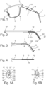
- In the following, the invention will be described in detail with reference to the accompanying drawings, where
- Fig. 1
- shows a partial perspective view of a pair of spectacles with a spectacle rod according to the invention;
- Fig. 2
- shows a side view, partly in section, of the spectacle rod of
Fig. 1 ; - Fig. 3
- shows a partial side view of the spectacle rod of
Fig. 1 ; - Fig. 4
- shows a top view of the spectacle rod of
Fig. 3 ; - Fig. 5A
- shows an enlarged cross-section according to the arrows A-A of
Fig. 3 ; - Fig. 5B
- shows a cross-section similar to
Fig. 5A of a second embodiment; - Fig. 6
- shows a side view of the metal rod of
Fig. 1 without a friction element attached; - Fig. 7
- shows a partial, enlarged image of the metal rod of
Fig. 6 ; - Fig. 8
- shows a section through the friction element shown in
Fig. 1 ; - Fig. 9
- shows a partial, enlarged image through the sectional view of
Fig. 8 ; and - Fig. 10
- shows an enlarged, partial view of the metal rod and friction element with the friction element shown in section.
- In the following, identical or similar elements of the different figures of the drawings will be designated by the same reference designation. Thus, an explanation of all details associated with each individual figure will not be given.
-
Fig. 1 shows a partial view of a pair of spectacles 1. The spectacles include a spectacle rod in the form of ametal rod 2, which is connected via a hinge 3 to a front piece 4. In the front piece 4, a spectacle lens 5 is provided in a frame. The front piece 4 further comprises anose pad 6 for abutment with the nose of the user. - The
metal rod 2 has anear bend 7. At theear bend 7, afriction element 8 is mounted in a position where there will be contact behind the ear of a user. Thefriction element 8 is manufactured from an elastic, compliant material, preferably an elastic polymer. - As can be seen, the
metal rod 2 is plate-shaped, having a significantly greater height 9 thanthickness 10. -
Fig. 2 shows themetal rod 2 with thefriction element 8 shown in section. In the bottom face of the metal rod, arecess 11 is provided, in which the friction element is partially received. In therecess 11, the metal rod is provided with a number of transversesecond protrusions 12. Thesesecond protrusions 12 are mushroom-shaped or arrow-shaped, so that they have a smaller cross-section at their connection to themetal rod 2 than their cross-section at a distance from the metal rod. Theprotrusions 12 are mounted with a snap effect in transversesecond holes 13 in thefriction element 8 and will be retained therein by a clamping force exerted due to the elastic compliance of the friction element material. - It can be said that a snap effect is thereby achieved, since the
protrusions 12 are pressed into theholes 13. - As is particularly clear from
Figs. 3 to 5 , the friction element has a conduit shape with aconduit 14 for receiving themetal rod 2. The conduit includes twoside walls 15 and a bottom 15'. The side walls havesurfaces 16, which are in abutment with side faces 17 of themetal rod 2. Likewise, the bottom 15' will have abottom face 18, which is in contact with abottom face 19 of themetal rod 2. Themetal rod 2 has atop face 20 that extends over thefriction element 8. -
Figs. 5A and 5B show an enlarged cross-section through the spectacle rod between thetransverse projections 12 on themetal rod 2. -
Fig. 5A and Fig. 5B further show that thesidewalls 15 have a decreasing thickness upwards in the direction of the side faces 17 of themetal rod 2. This provides a smooth transition between the outside of the friction element and themetal rod 2. However, there is anupper side 21 on theside walls 15, which the user may use as a pressure surface when thefriction element 8 is to be separated from themetal rod 2. -
Fig. 5A shows an embodiment in which theconduit 14 is formed with smaller width than the thickness of themetal rod 2, so that theconduit side walls 15 are in elastic abutment with the side faces 17 of the metal rod. -
Fig. 5B shows an embodiment in which theconduit 14 is formed with the same width as the thickness of themetal rod 2, so that theconduit side walls 15 are in abutment with the side faces 17 of the metal rod, without any elastic clamping effect. Between theside walls 15 and the side faces 17, a glue joint 46 is provided to ensure the retention of the friction element against the side faces 17 of the metal rod. -
Fig. 3 shows an enlarged side view in the area of theear bend 7.Fig. 3 shows a section line A-A for the position in which the sectional view ofFig. 5 is made. It can be seen fromFig. 3 that a narrow marginal edge area 20' (see alsoFig. 5 ) on themetal rod 2 is above theupper side 21. Thus, a user will be able to easily grab hold at theupper side 21 and pull the friction element in the transverse direction to free it from the engagement with theprotrusions 12 when the friction element is to be replaced. -
Fig. 2 shows themetal rod 2, which has a first end 22' for attachment to the front piece, and asecond end 22 farthest away from the front piece 4. At the outermostsecond end 22, the metal rod has a transversefirst protrusion 23. -
Figs. 6 and 7 show more clearly the design of thefirst projection 23 and thesecond projections 12 on themetal rod 2. - The
metal rod 2 has alongitudinal direction 24 and atransverse direction 25, as indicated inFigs. 6 and 7 . Thelongitudinal direction 24 and thetransverse direction 25 of the metal rod correspond to the longitudinal direction and transverse direction of the spectacle rod. - The
first protrusion 23 extends in thetransverse direction 25 and with an oblique course in thelongitudinal direction 24. Thus, thefirst projection 23 together with the outermostsecond end part 22 of the spectacle rod will form arecess 26 that is open in the longitudinal direction. - The
recess 26 has anopening 27, which has a smaller cross-section than the cross-section that will be provided at acentral part 28 of therecess 26. At theopening 27 of the recess, thefirst protrusion 23 is provided with a hook-shapedprotrusion 29. This hook-shapedprotrusion 29 helps to create thesmaller opening 27 and at the same time will contribute to a safe retention of elastically compliant material from the friction element when the friction element is mounted on the metal rod, as illustrated for example inFig. 2 andFig. 10 . -
Figs. 8 and9 show sectional views through thefriction element 8. As is particularly clear fromFig. 9 , thefriction element conduit 14 is closed by amaterial quantity 30 at thefirst end 31 of the friction element. At thesecond end 32 of the friction element, theconduit 14 is open. - As is particularly clear from
Fig. 9 , at itsfirst end part 31 the friction element is provided with a firsttransverse hole 33 in thematerial quantity 30 which closes theconduit 14. Thishole 33 serves to receive the transversefirst protrusion 23 of the metal rod. - As can be seen from
Fig. 10 , thematerial quantity 34 which delimits the transversefirst hole 33 will be deformed when mounted on themetal rod 2. This ensures a retaining grip between thefriction element 8 and themetal rod 2, so that the friction element cannot be inadvertently displaced in the longitudinal direction or the transverse direction. The engagement between thefirst protrusion 23 and the firsttransverse hole 33 as well as thematerial quantity 34 can be said to constitute the first retaining means. - The
second protrusions 12 and thesecond holes 13 can be said to constitute second retaining means between thefriction element 8 and themetal rod 2. -
Fig. 7 shows that themetal rod 2 at its outermostsecond end 22 is provided with agroove 35. Thisgroove 35 serves to receive a protrudingmaterial part 36 at thefirst end 31 of thefriction element 8. - As can be seen from
Fig. 10 , it is hereby ensured that the outer end face 37 of themetal rod 2 lies level with the outer end face 38 of thefriction element 8, the friction element face 39 being in abutment with theface 40 of themetal rod 2 in thegroove 35. - In
Fig. 8 , thesecond holes 30 of thefriction element 8 are shown with anopening 41 that has a smaller cross-section than that of the holes at acentral part 42 of the second holes 13. This achieves a secure retention of the transversesecond protrusions 12. As is particularly clear fromFig. 10 , after the introduction of the transversesecond protrusions 12, an elastic deformation of the friction element material will be provided, which contributes to the safe retention, as thesecond protrusions 12 are received in thesecond holes 13 with a clamping effect. - Similarly, the
first protrusion 23 of the spectacle rod will have a size larger than the transversefirst hole 33 of the friction element, so that, here too, receiving takes place with a clamping effect. -
Fig. 6 shows that themetal rod 2 in anintermediate part 43 has aabutment face 44 at the end of therecess 11. Thisabutment face 44 serves for abutment with an end face 45 (seeFig. 8 ) of thefriction element 8 when this is mounted on themetal rod 2. This establishes further safety against an accidental displacement of thefriction element 8 relative to themetal rod 2.
Claims (10)
- A spectacle rod with a first end part (22') intended for connection with a front piece (4), as well as a second end part (22) intended to be bent to form an ear bend (7), said spectacle rod having a longitudinal direction (24) and a transverse direction (25), and said spectacle rod being formed, at least above the second end part (22) of the spectacle rod, by a plate-shaped rod (2) having side faces (17) as well as bottom and top faces (19, 20), and wherein a friction element (8) made from an elastic, compliant material is connected to the plate-shaped rod (2) in a position at the ear bend (7) for contact behind the ear of a user, and wherein the plate-shaped rod (2) has a first transverse protrusion (23), which first transverse protrusion (23) is directed in the transverse direction (25) and obliquely in the longitudinal direction (24) in order to form, together with the second end part of the metal rod, a longitudinally open recess (26), and wherein, in the first end part (31) of the friction element, a first transverse hole (33) is provided for receiving the first transverse protrusion(23) of the plate-shaped rod, and wherein the plate-shaped rod is a metal rod, and wherein the friction element (8) is conduit-shaped so that the conduit walls (15) and bottom (15') cover the side faces (20) and the bottom face (19) of the metal rod, and wherein the first transverse hole (33) of the friction element is formed in the material quantity (30) and directed in the transverse direction (25) in order to receive the first transverse protrusion (23) of the metal rod, and wherein elastic material at the first end part (31) of the friction element is received in the open recess (26) of the metal rod, so that the first transverse protrusion (23) and the recess (26) form first retaining means, and wherein between the walls (15) and the bottom (15') of the conduit and the side faces (17) of the metal rod, further retaining means are provided which prevent the displacement of the friction element in the longitudinal direction (24) and transverse direction (25) of the metal rod, characterized in that the first transverse protrusion (23) of the plate-shaped rod (2) is provided at its outermost second end (22), in that the longitudinally open recess (26) is form, together with the outermost second end part (22) of the metal rod, which longitudinally open recess (26) has at its opening (27) a smaller cross-section than at a central part (28) of the recess (26), in that the friction element (8) at a first end of the conduit (14) is closed by a material quantity (30) at the first end (31) of the friction element, in that the first transverse hole (33) of the friction element is also directed obliquely in the longitudinal direction (24), in that elastic material at the first end part (31) of the friction element is received in the open recess (26) of the metal rod in an elastically compressed state.
- The spectacle rod according to claim 1, characterised in that the metal rod (2) at its bottom face (19) is provided with transverse second protrusions (12) for releasable snap engagement with second holes (13) in the bottom (15') of the conduit, wherein the second protrusions (12) at their connection to the metal rod (2) have a smaller cross-section than that of the second protrusions at a distance from the metal rod (2), so that the second protrusions (12) are retained in the second holes (13) at the bottom (15') of the conduit due to the elastic compliance of the friction element (8) material.
- The spectacle rod according to claims 1 or 2, characterised in that a transverse protrusion (29) is formed at the opening (27) of the recess (26), preferably a hook-shaped protrusion (29), on the first transverse protrusion (23) and/or on the outermost second end part (22) of the metal rod.
- The spectacle rod according to claims 1, 2 or 3, characterised in that the first hole (33) in the friction element (8) is made with a size smaller than that of the first protrusion (23) of the metal rod, so that the first protrusion (23) of the metal rod is received therein with a clamping effect.
- The spectacle rod according to any of the previous claims, characterised in that the conduit (14) is formed with a smaller width than the thickness of the metal rod (2), so that the conduit side walls (15) are in elastic abutment with the side faces (17) of the metal rod.
- The spectacle rod according to any of the previous claims, characterised in that the metal rod (2) in an intermediate part (43), at the side facing the second protrusions (12) of the metal rod, has a abutment face (44) for an end face (45) of the friction element (8).
- The spectacle rod according to any of the previous claims, characterised in that the friction element (8) covers at least part of the outermost end face of the second end part (22) of the metal rod.
- The spectacle rod according to any of the previous claims, characterised in that the metal rod (2) is made from titanium.
- The spectacle rod according to any of the previous claims, characterised in that the side walls (15) of the friction element conduit (14) have decreasing thickness towards the side faces (17) of the metal rod to form a smooth transition.
- The spectacle rod according to any of the previous claims, characterised in that the metal rod (2) at its outermost second end part (22) has a groove (35), where an end part (36) of the friction element (8) is in abutment.
Priority Applications (1)
| Application Number | Priority Date | Filing Date | Title |
|---|---|---|---|
| HRP20251140TT HRP20251140T1 (en) | 2021-05-03 | 2022-05-03 | GLASSES WITH FRICTION ELEMENT ON THE FLEX BEHIND THE EAR |
Applications Claiming Priority (2)
| Application Number | Priority Date | Filing Date | Title |
|---|---|---|---|
| DKPA202170202A DK180937B1 (en) | 2021-05-03 | 2021-05-03 | GLASSES BAR WITH FRICTION ELEMENT AT EAR BUCKLE |
| PCT/DK2022/050090 WO2022233378A1 (en) | 2021-05-03 | 2022-05-03 | Spectacle rod with friction element at ear bend |
Publications (3)
| Publication Number | Publication Date |
|---|---|
| EP4334775A1 EP4334775A1 (en) | 2024-03-13 |
| EP4334775B1 true EP4334775B1 (en) | 2025-07-02 |
| EP4334775C0 EP4334775C0 (en) | 2025-07-02 |
Family
ID=81749124
Family Applications (1)
| Application Number | Title | Priority Date | Filing Date |
|---|---|---|---|
| EP22724421.7A Active EP4334775B1 (en) | 2021-05-03 | 2022-05-03 | Spectacle rod with friction element at ear bend |
Country Status (13)
| Country | Link |
|---|---|
| US (1) | US20240201516A1 (en) |
| EP (1) | EP4334775B1 (en) |
| JP (1) | JP7654111B2 (en) |
| KR (1) | KR20240016971A (en) |
| CN (1) | CN117203568B (en) |
| BR (1) | BR112023020394A2 (en) |
| DK (1) | DK180937B1 (en) |
| ES (1) | ES3047128T3 (en) |
| HR (1) | HRP20251140T1 (en) |
| HU (1) | HUE072866T2 (en) |
| MX (1) | MX2023012993A (en) |
| PL (1) | PL4334775T3 (en) |
| WO (1) | WO2022233378A1 (en) |
Family Cites Families (17)
| Publication number | Priority date | Publication date | Assignee | Title |
|---|---|---|---|---|
| US3402005A (en) * | 1965-02-12 | 1968-09-17 | Fendall Co | Multi-fit temple having a notched, bendable ear portion and plastic cover member |
| DE3237501C2 (en) | 1982-10-09 | 1987-01-08 | Marwitz & Hauser GmbH, 7000 Stuttgart | Temples |
| US5002381A (en) * | 1989-02-17 | 1991-03-26 | Murrell Edmond E | Eyewear retainer |
| US5610669A (en) * | 1995-07-10 | 1997-03-11 | Kuipers; Raymond J. | Temple for eyeglasses embodying an integrally formed ear piece |
| US5623322A (en) * | 1995-12-04 | 1997-04-22 | Hudson Optical Corporation | Pull down member on temple of eyeglasses |
| JP2922167B2 (en) * | 1996-11-05 | 1999-07-19 | 株式会社長井芯張工業所 | Method for manufacturing resin eyeglass member |
| FR2763143B1 (en) * | 1997-05-07 | 1999-07-23 | Salino Et Fils | EYEWEAR FRAME |
| US6045221A (en) | 1999-05-17 | 2000-04-04 | Resendez, Sr.; Julio | Eyeglasses clip |
| JP4070777B2 (en) | 2005-04-11 | 2008-04-02 | 株式会社ビジョンメガネ | Temple for glasses frame |
| US7165838B1 (en) * | 2006-05-24 | 2007-01-23 | Leslie Sapp | Tensioning eyewear |
| WO2011085254A1 (en) * | 2010-01-08 | 2011-07-14 | Oakley, Inc. | Eyewear earstem devices and methods |
| US20140132911A1 (en) | 2011-06-30 | 2014-05-15 | PLANET VISION 60 Co., Ltd. | Temple for eyeglass frame, and method for producing temple |
| CN203037941U (en) | 2012-10-22 | 2013-07-03 | 温州市瓯海东田眼镜制造有限公司 | Spectacle pin |
| CN203535327U (en) * | 2013-10-31 | 2014-04-09 | 温州市川豪光学有限公司 | Glasses with comb |
| CN205656381U (en) * | 2016-03-18 | 2016-10-19 | 林苏 | Novel glasses leg catapult hinge structure of no auxiliary member |
| DK178971B1 (en) | 2016-03-30 | 2017-07-17 | Lindberg As | Eyeglasses and method of making eyeglasses |
| KR20200001172U (en) | 2018-11-28 | 2020-06-05 | 안명희 | Glasses legs with center of gravity movement |
-
2021
- 2021-05-03 DK DKPA202170202A patent/DK180937B1/en active IP Right Grant
-
2022
- 2022-05-03 PL PL22724421.7T patent/PL4334775T3/en unknown
- 2022-05-03 WO PCT/DK2022/050090 patent/WO2022233378A1/en not_active Ceased
- 2022-05-03 KR KR1020237041565A patent/KR20240016971A/en active Pending
- 2022-05-03 US US18/289,042 patent/US20240201516A1/en active Pending
- 2022-05-03 ES ES22724421T patent/ES3047128T3/en active Active
- 2022-05-03 MX MX2023012993A patent/MX2023012993A/en unknown
- 2022-05-03 EP EP22724421.7A patent/EP4334775B1/en active Active
- 2022-05-03 HU HUE22724421A patent/HUE072866T2/en unknown
- 2022-05-03 BR BR112023020394A patent/BR112023020394A2/en unknown
- 2022-05-03 CN CN202280025317.3A patent/CN117203568B/en active Active
- 2022-05-03 JP JP2023567988A patent/JP7654111B2/en active Active
- 2022-05-03 HR HRP20251140TT patent/HRP20251140T1/en unknown
Also Published As
| Publication number | Publication date |
|---|---|
| HUE072866T2 (en) | 2025-12-28 |
| HRP20251140T1 (en) | 2025-11-21 |
| US20240201516A1 (en) | 2024-06-20 |
| DK180937B1 (en) | 2022-07-01 |
| JP2024516295A (en) | 2024-04-12 |
| EP4334775A1 (en) | 2024-03-13 |
| MX2023012993A (en) | 2023-11-15 |
| WO2022233378A1 (en) | 2022-11-10 |
| TW202303231A (en) | 2023-01-16 |
| PL4334775T3 (en) | 2025-11-17 |
| CN117203568B (en) | 2026-01-23 |
| CN117203568A (en) | 2023-12-08 |
| ES3047128T3 (en) | 2025-12-03 |
| DK202170202A1 (en) | 2022-07-01 |
| BR112023020394A2 (en) | 2023-11-28 |
| JP7654111B2 (en) | 2025-03-31 |
| EP4334775C0 (en) | 2025-07-02 |
| KR20240016971A (en) | 2024-02-06 |
Similar Documents
| Publication | Publication Date | Title |
|---|---|---|
| US7658492B2 (en) | Rimless spectacles | |
| US6139143A (en) | Temple for eyewear having an integrally formed serpentine hinge | |
| AU719220B2 (en) | Spring temple for eyewear | |
| MXPA06012998A (en) | Floating lens brow bar attachment for eyeglasses. | |
| EP2162782B1 (en) | Hinge arrangement for spectacles | |
| CN109938443B (en) | Goggles with replaceable buckle | |
| US7967431B2 (en) | Spectacles | |
| US20240201516A1 (en) | Spectacle rod with friction element at ear bend | |
| AU720021B2 (en) | Dual rate spring-action eyewear temple | |
| KR102366742B1 (en) | Temple Bars and How to Craft Temple Bars | |
| TWI918917B (en) | Spectacle rod with friction element at ear bend | |
| KR100626468B1 (en) | A pair of spectacles and method for their manufacturing | |
| JP6991578B2 (en) | Eyeglass frame | |
| AU5589198A (en) | Hingeless eyewear temple | |
| HK40098218B (en) | Spectacle rod with friction element at ear bend | |
| HK40098218A (en) | Spectacle rod with friction element at ear bend | |
| EP1288701A2 (en) | Lens mounting mechanism of spectacle lens mounting member, auxiliary spectacles and spectacles | |
| BR112019002664B1 (en) | CABLE FOR A SHAVING OR ELIMINATING DEVICE | |
| HK40000294A (en) | Temple bar and a method of manufacturing a temple bar | |
| HK40000294B (en) | Temple bar and a method of manufacturing a temple bar |
Legal Events
| Date | Code | Title | Description |
|---|---|---|---|
| REG | Reference to a national code |
Ref country code: HR Ref legal event code: TUEP Ref document number: P20251140T Country of ref document: HR |
|
| STAA | Information on the status of an ep patent application or granted ep patent |
Free format text: STATUS: UNKNOWN |
|
| STAA | Information on the status of an ep patent application or granted ep patent |
Free format text: STATUS: THE INTERNATIONAL PUBLICATION HAS BEEN MADE |
|
| PUAI | Public reference made under article 153(3) epc to a published international application that has entered the european phase |
Free format text: ORIGINAL CODE: 0009012 |
|
| STAA | Information on the status of an ep patent application or granted ep patent |
Free format text: STATUS: REQUEST FOR EXAMINATION WAS MADE |
|
| 17P | Request for examination filed |
Effective date: 20231010 |
|
| AK | Designated contracting states |
Kind code of ref document: A1 Designated state(s): AL AT BE BG CH CY CZ DE DK EE ES FI FR GB GR HR HU IE IS IT LI LT LU LV MC MK MT NL NO PL PT RO RS SE SI SK SM TR |
|
| DAX | Request for extension of the european patent (deleted) | ||
| RAV | Requested validation state of the european patent: fee paid |
Extension state: KH Effective date: 20231019 |
|
| GRAP | Despatch of communication of intention to grant a patent |
Free format text: ORIGINAL CODE: EPIDOSNIGR1 |
|
| STAA | Information on the status of an ep patent application or granted ep patent |
Free format text: STATUS: GRANT OF PATENT IS INTENDED |
|
| INTG | Intention to grant announced |
Effective date: 20241210 |
|
| GRAS | Grant fee paid |
Free format text: ORIGINAL CODE: EPIDOSNIGR3 |
|
| GRAA | (expected) grant |
Free format text: ORIGINAL CODE: 0009210 |
|
| STAA | Information on the status of an ep patent application or granted ep patent |
Free format text: STATUS: THE PATENT HAS BEEN GRANTED |
|
| AK | Designated contracting states |
Kind code of ref document: B1 Designated state(s): AL AT BE BG CH CY CZ DE DK EE ES FI FR GB GR HR HU IE IS IT LI LT LU LV MC MK MT NL NO PL PT RO RS SE SI SK SM TR |
|
| REG | Reference to a national code |
Ref country code: GB Ref legal event code: FG4D |
|
| REG | Reference to a national code |
Ref country code: CH Ref legal event code: EP |
|
| REG | Reference to a national code |
Ref country code: DE Ref legal event code: R096 Ref document number: 602022016899 Country of ref document: DE |
|
| REG | Reference to a national code |
Ref country code: IE Ref legal event code: FG4D |
|
| U01 | Request for unitary effect filed |
Effective date: 20250715 |
|
| U07 | Unitary effect registered |
Designated state(s): AT BE BG DE DK EE FI FR IT LT LU LV MT NL PT RO SE SI Effective date: 20250721 |
|
| REG | Reference to a national code |
Ref country code: SK Ref legal event code: T3 Ref document number: E 47145 Country of ref document: SK |
|
| REG | Reference to a national code |
Ref country code: HR Ref legal event code: T1PR Ref document number: P20251140 Country of ref document: HR |
|
| REG | Reference to a national code |
Ref country code: ES Ref legal event code: FG2A Ref document number: 3047128 Country of ref document: ES Kind code of ref document: T3 Effective date: 20251203 |
|
| REG | Reference to a national code |
Ref country code: HU Ref legal event code: AG4A Ref document number: E072866 Country of ref document: HU |
|
| PG25 | Lapsed in a contracting state [announced via postgrant information from national office to epo] |
Ref country code: IS Free format text: LAPSE BECAUSE OF FAILURE TO SUBMIT A TRANSLATION OF THE DESCRIPTION OR TO PAY THE FEE WITHIN THE PRESCRIBED TIME-LIMIT Effective date: 20251102 |
|
| PG25 | Lapsed in a contracting state [announced via postgrant information from national office to epo] |
Ref country code: NO Free format text: LAPSE BECAUSE OF FAILURE TO SUBMIT A TRANSLATION OF THE DESCRIPTION OR TO PAY THE FEE WITHIN THE PRESCRIBED TIME-LIMIT Effective date: 20251002 |
|
| PG25 | Lapsed in a contracting state [announced via postgrant information from national office to epo] |
Ref country code: GR Free format text: LAPSE BECAUSE OF FAILURE TO SUBMIT A TRANSLATION OF THE DESCRIPTION OR TO PAY THE FEE WITHIN THE PRESCRIBED TIME-LIMIT Effective date: 20251003 |
|
| PG25 | Lapsed in a contracting state [announced via postgrant information from national office to epo] |
Ref country code: RS Free format text: LAPSE BECAUSE OF FAILURE TO SUBMIT A TRANSLATION OF THE DESCRIPTION OR TO PAY THE FEE WITHIN THE PRESCRIBED TIME-LIMIT Effective date: 20251002 |
|
| PG25 | Lapsed in a contracting state [announced via postgrant information from national office to epo] |
Ref country code: SM Free format text: LAPSE BECAUSE OF FAILURE TO SUBMIT A TRANSLATION OF THE DESCRIPTION OR TO PAY THE FEE WITHIN THE PRESCRIBED TIME-LIMIT Effective date: 20250702 |
|
| PGFP | Annual fee paid to national office [announced via postgrant information from national office to epo] |
Ref country code: GB Payment date: 20260326 Year of fee payment: 5 |
|
| U20 | Renewal fee for the european patent with unitary effect paid |
Year of fee payment: 5 Effective date: 20260329 |
|
| PLBE | No opposition filed within time limit |
Free format text: ORIGINAL CODE: 0009261 |
|
| REG | Reference to a national code |
Ref country code: HR Ref legal event code: ODRP Ref document number: P20251140 Country of ref document: HR Payment date: 20260416 Year of fee payment: 5 |
|
| STAA | Information on the status of an ep patent application or granted ep patent |
Free format text: STATUS: NO OPPOSITION FILED WITHIN TIME LIMIT |