EP4334112B1 - Film trimming device and method - Google Patents
Film trimming device and method Download PDFInfo
- Publication number
- EP4334112B1 EP4334112B1 EP22731788.0A EP22731788A EP4334112B1 EP 4334112 B1 EP4334112 B1 EP 4334112B1 EP 22731788 A EP22731788 A EP 22731788A EP 4334112 B1 EP4334112 B1 EP 4334112B1
- Authority
- EP
- European Patent Office
- Prior art keywords
- shim
- film
- jig
- panel
- ditch portion
- Prior art date
- Legal status (The legal status is an assumption and is not a legal conclusion. Google has not performed a legal analysis and makes no representation as to the accuracy of the status listed.)
- Active
Links
Images


Classifications
-
- B—PERFORMING OPERATIONS; TRANSPORTING
- B29—WORKING OF PLASTICS; WORKING OF SUBSTANCES IN A PLASTIC STATE IN GENERAL
- B29C—SHAPING OR JOINING OF PLASTICS; SHAPING OF MATERIAL IN A PLASTIC STATE, NOT OTHERWISE PROVIDED FOR; AFTER-TREATMENT OF THE SHAPED PRODUCTS, e.g. REPAIRING
- B29C63/00—Lining or sheathing, i.e. applying preformed layers or sheathings of plastics; Apparatus therefor
- B29C63/48—Preparation of the surfaces
- B29C63/481—Preparation of the surfaces mechanically
-
- B—PERFORMING OPERATIONS; TRANSPORTING
- B29—WORKING OF PLASTICS; WORKING OF SUBSTANCES IN A PLASTIC STATE IN GENERAL
- B29C—SHAPING OR JOINING OF PLASTICS; SHAPING OF MATERIAL IN A PLASTIC STATE, NOT OTHERWISE PROVIDED FOR; AFTER-TREATMENT OF THE SHAPED PRODUCTS, e.g. REPAIRING
- B29C63/00—Lining or sheathing, i.e. applying preformed layers or sheathings of plastics; Apparatus therefor
- B29C63/0004—Component parts, details or accessories; Auxiliary operations
-
- B—PERFORMING OPERATIONS; TRANSPORTING
- B29—WORKING OF PLASTICS; WORKING OF SUBSTANCES IN A PLASTIC STATE IN GENERAL
- B29C—SHAPING OR JOINING OF PLASTICS; SHAPING OF MATERIAL IN A PLASTIC STATE, NOT OTHERWISE PROVIDED FOR; AFTER-TREATMENT OF THE SHAPED PRODUCTS, e.g. REPAIRING
- B29C63/00—Lining or sheathing, i.e. applying preformed layers or sheathings of plastics; Apparatus therefor
- B29C63/0082—Finishing the edges of holes or perforations in the lined product
-
- B—PERFORMING OPERATIONS; TRANSPORTING
- B29—WORKING OF PLASTICS; WORKING OF SUBSTANCES IN A PLASTIC STATE IN GENERAL
- B29C—SHAPING OR JOINING OF PLASTICS; SHAPING OF MATERIAL IN A PLASTIC STATE, NOT OTHERWISE PROVIDED FOR; AFTER-TREATMENT OF THE SHAPED PRODUCTS, e.g. REPAIRING
- B29C63/00—Lining or sheathing, i.e. applying preformed layers or sheathings of plastics; Apparatus therefor
- B29C63/02—Lining or sheathing, i.e. applying preformed layers or sheathings of plastics; Apparatus therefor using sheet or web-like material
-
- B—PERFORMING OPERATIONS; TRANSPORTING
- B29—WORKING OF PLASTICS; WORKING OF SUBSTANCES IN A PLASTIC STATE IN GENERAL
- B29C—SHAPING OR JOINING OF PLASTICS; SHAPING OF MATERIAL IN A PLASTIC STATE, NOT OTHERWISE PROVIDED FOR; AFTER-TREATMENT OF THE SHAPED PRODUCTS, e.g. REPAIRING
- B29C2793/00—Shaping techniques involving a cutting or machining operation
- B29C2793/0009—Cutting out
-
- B—PERFORMING OPERATIONS; TRANSPORTING
- B29—WORKING OF PLASTICS; WORKING OF SUBSTANCES IN A PLASTIC STATE IN GENERAL
- B29C—SHAPING OR JOINING OF PLASTICS; SHAPING OF MATERIAL IN A PLASTIC STATE, NOT OTHERWISE PROVIDED FOR; AFTER-TREATMENT OF THE SHAPED PRODUCTS, e.g. REPAIRING
- B29C2793/00—Shaping techniques involving a cutting or machining operation
- B29C2793/009—Shaping techniques involving a cutting or machining operation after shaping
-
- B—PERFORMING OPERATIONS; TRANSPORTING
- B29—WORKING OF PLASTICS; WORKING OF SUBSTANCES IN A PLASTIC STATE IN GENERAL
- B29L—INDEXING SCHEME ASSOCIATED WITH SUBCLASS B29C, RELATING TO PARTICULAR ARTICLES
- B29L2031/00—Other particular articles
- B29L2031/30—Vehicles, e.g. ships or aircraft, or body parts thereof
- B29L2031/3005—Body finishings
-
- B—PERFORMING OPERATIONS; TRANSPORTING
- B29—WORKING OF PLASTICS; WORKING OF SUBSTANCES IN A PLASTIC STATE IN GENERAL
- B29L—INDEXING SCHEME ASSOCIATED WITH SUBCLASS B29C, RELATING TO PARTICULAR ARTICLES
- B29L2031/00—Other particular articles
- B29L2031/30—Vehicles, e.g. ships or aircraft, or body parts thereof
- B29L2031/3055—Cars
Definitions
- the film can be, for example, an adhesive-backed film applied to an automotive exterior surface.
- the target applications areas can include the whole roof area, roof side, or the entire vehicle.
- Especially useful types of film are paint film and blackout film, which have potential to replace application of liquid paint in many applications. Use of these films can save significant time when compared with multiple applications of paint while avoiding emissions of volatile organic compounds.
- Other useful films include paint protection films that are applied over previously painted surfaces. All of these surfacing films can provide both functional and decorative benefits.
- US 10 357 952 B2 discloses methods of applying an adhesive-backed film to the surface of a vehicle and cutting the film to fit the surface using a separate cutting tool guide structure.
- a trimming and application device to apply tape or film on a three-dimensional surface.
- This application device is a jig that includes a thin metal shim received into an elongated and flexible body capable of contouring to the 3D surface.
- a tool is pressed against the film, pressing the film into a corner of the metal shim.
- the applied pressure cuts the film without need for a sharp cutting blade.
- wet-out near the trimmed edge can proceed with help of the device's angled shelves.
- the angled shelves reduce tenting on the film edges by allowing sequential geometry radii to be wet-out in the proper order, limiting variability of the operator and reducing the chance of trapping air under the film during application.
- the custom cut profiles can accommodate already installed roof-ditch clips with a pocket design.
- the said device quickly snaps into place with its flexible design and magnetic surfaces but is not limited to such.
- This trimming application is not limited to roof ditch and could be used in other trim areas that do not have an exposed edge.
- the provided jig and method provides for an easy application with limited operator skill, reduces safety concern as there are no sharp objects, and adds repeatability as the film cutting location is fixed. This solution also reduces film trim and final wet-out time while reducing the level of skill needed by the operator.
- a method of applying a film to a first panel of a vehicle comprises: placing into the ditch portion an elongated jig that comprises a shim extending continuously along the length of the ditch portion, the shim protruding above a height of the first panel; applying the film to the first and second panels such that the film extends over the elongated jig; using a tool to apply pressure against the film and toward a cutting edge of the shim along the length of the shim to trim the film along a peripheral edge; removing the elongated jig from the ditch portion; and adhering the peripheral edge of the film to the ditch portion.
- a jig for applying a film to a first panel of a vehicle that is connected to a second panel of the vehicle by a joint area containing a ditch portion that is recessed relative to the first panel, the jig comprising: an elongated body having a convex bottom surface complemental to the ditch portion, the elongated body having a plurality of discontinuous segments; and a shim extending continuously along the length of the elongated body, wherein the shim has a cutting edge facing away from the elongated body and having a convergence angle of from 60 degrees to 120 degrees.
- the terms “preferred” and “preferably” refer to embodiments described herein that can afford certain benefits, under certain circumstances. However, other embodiments may also be preferred, under the same or other circumstances.
- a jig according to one exemplary embodiment is shown in FIG. 1 and hereinafter referred to be the numeral 100.
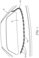
- the jig 100 has an elongated shape and is shown on top of an automotive roof panel 50 for size comparison.
- the jig 100 is comprised of a continuous shim 102 (or wire) extending along the length of the jig 100 and a plurality of discontinuous segments 104 coupled to the shim 102 and distributed along its length.
- the segments 104 are joined to each other only by the shim 102.
- the segments 104 could also include mechanical hinges allowing adjacent segments 104 to couple to each other.
- the segments 104 can be made modular in nature to accommodate different panel sizes and shapes.
- the provided embodiments are directed to the roof panel of an automobile, these could easily be applied to other panels as well.
- the provided jigs and methods could generally be used to facilitate the trimming of film near the roof ditch, front windshield, rear windshield, and moonroof of a vehicle. These jigs and methods also need not be limited to vehicular applications, and could be adapted for use on other large assemblies in which two or more exterior-facing panels come together along a seam that defines a registration surface.
- the discontinuous nature of the segments 104 enables the relatively thin shim 102 to flexibly trace along a recessed ditch portion 52 defining a perimeter of the roof panel 50, even if the segments 104 themselves are relatively inflexible.
- the ditch portion 52 which will be described later in more detail, defines the boundaries of the area over which a film is to be applied. In some cases, but not necessarily all cases, the ditch portion 52 defines a boundary between contiguous panels.
- the shim 102 can be made from a metal, such as steel, aluminum, nitinol, copper, or alloy thereof.
- the metal is highly elastic and resists permanent deformation when flexed, for example, around a corner portion of a panel.
- the material of the shim 102 is not necessarily limited to metals, however, and can also be made from a flexible polymer or ceramic material.
- the segments 104 are also at least somewhat flexible, being made from a pliable material such as a polymer, allowing flexibility and potentially lateral expansion or contraction of the material along the segments 104. Such properties can also help the segments 104 better conform to the ditch portion 52 and potentially aid in securement.
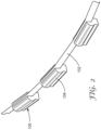
- FIG. 2 shows an enlarged view of the jig 100 showing its profile along its longitudinal axis.
- the shim 102 has a generally rectangular cross-sectional shape, where the cross-section is defined perpendicular to a longitudinal axis of the shim 102.
- the shim 102 is partially embedded in each segment 104 such that one of the narrow faces of the shim 102 faces upward (i.e., away from the vehicle panel when installed) and is fully exposed along the entire length of the jig 100. It is preferable for the shim 102 to protrude above the top surface of the segments 104 by a certain amount. As an example, at least 5 percent, at least 10 percent, or at least 15 percent of the shim 102 can protrude above the segments 104.
- the vertical dimension of the shim 102 is far greater than the transverse dimension, thus allowing for a high degree of flexibility along transverse directions.
- Non-rectangular shapes are also possible, so long as the cross-section of the shim has at least one upward-facing corner that protrudes above the segments 104, thereby providing a continuous cutting edge for the film.
- the upward-facing portion of the shim 102 can have a generally "D"-shaped cross-section.
- the cross-section of the shim 102 may or may not be uniform along its length.
- the shim 102 includes one or more notches along its bottom-facing surface to facilitate bending of the shim along the plane of the roof panel 50.
- each of the two cutting edges protruding above the segments 104 has by definition a convergence angle of 90 degrees, the convergence angle being defined as the angle at which the adjacent sides of the shim come together.
- the one or more cutting edges can have convergence angles that deviate from 90 degrees.
- a given cutting edge can have a convergence angle of from 60 degrees to 120 degrees, from 60 degrees to 90 degrees, from 80 degrees to 90 degrees, or in some embodiments, less than, equal to, or greater than 60 degrees, 65, 70, 75, 80, 85, 90, 95, 100, 105, 110, 115, or 120 degrees.
- At least one cutting edge of the shim 102 preferably has a corner edge suitable to cut through a film, such as a corner radius of up to 400 micrometers, up to 200 micrometers, up to 100 micrometers, or up to 10 micrometers.
- the transverse thickness of the shim 102 can be from 100 micrometers to 400 micrometers, from 120 micrometers to 350 micrometers, from 150 micrometers to 300 micrometers, or in some embodiments, less than, equal to, or greater than 100 micrometers, 105, 110, 115, 120, 125, 130, 135, 140, 145, 150, 160, 170, 180, 190, 200, 220, 240, 250, 260, 280, 300, 320, 340, 350, 360, 380, or 400 micrometers.
- the aspect ratio (i.e., height/width) of the cross-section of the shim 102 can be from 15 to 127, from 20 to 80, from 40 to 60, or in some embodiments, less than, equal to, or greater than 15, 17, 20, 22, 25, 27, 30, 35, 40, 45, 50, 55, 60, 65, 70, 75, 80, 85, 90, 95, 100, 105, 110, 115, 120, 125, or 127.
- FIGS. 3A and 3B show opposing bottom and top sides of a customized segment 106 that can optionally be used in combination with the shim 102.
- the customized segment 106 contains a pocket 108 that provides space to accommodate any obstructions in the ditch portion 52 that would normally interfere with a segment, such as roof ditch clip 54 shown in FIG. 3A.
- FIG. 3B shows the upward-facing major surface of the customized segment 106, revealing a groove 110 for seating a shim (not shown in FIGS. 3A and 3B ).
- Use of the customized segment 106 can also be advantageous in guiding the shim 102 along particularly sharp bends, such as along corner portions of the vehicle panel. While not shown here, it is possible for the customized segment 106 to have a configuration in which it mechanically attaches to the clip 54 to provide a datum point for positioning the jig 100 relative to the roof panel 50.
- FIG. 4 shows, in more detail, an engagement between the jig 100, including the shim 102 and segments 104, and the ditch portion 52 of the roof panel 50.
- the ditch portion can extend along the boundary between two adjacent vehicle panels, for example between a roof panel and a side panel of the vehicle.
- the ditch portion preferably includes surfaces that are recessed relative to both panels.
- the ditch portion 52 includes both concave and convex surface regions represented by a double radius. These surface regions can be complemental to mating surfaces of the segment 104.
- the mating surfaces extend along at least two adjacent sides of each segment 104. These adjacent sides are generally bottom and side surfaces of the segment 104.
- the mating engagement between the segments 104 and the ditch portion 52 can significantly improve registration between the jig 100 and the roof panel 50. This in turn can provide a high degree of precision in the cut lines obtained using the jig 100 relative to those obtained by conventional methods.
- each segment 104 includes an angled shelf 51 disposed between the shim 102 and the roof panel 50.
- the angled shelf 51 can help reduce tenting on the edges of the film by allowing sequential geometry radii to be wet-out in the proper order. This reduces the chance of trapping air under the film during application.
- the angled shelf 51 can help limit variability in the quality of film application attributable to differences in operator technique.
- the jig 100 could be detected using fiducial markers on the jig 100 that assist in locating its position.
- This cutting step can take place along a continuous loop along the perimeter of the roof panel 50 as defined by the ditch portion 52. It is also possible for the ditch portion 52 to only extend along a portion of the perimeter of the roof panel 50, in which case more than one cutting step might be required to separate the portion of the film 120 disposed on the roof panel 50 from portions of the film 120 extending beyond the roof panel 50.
- the tool 122 has a recess 124 that has a shape that is complemental to the shape of the cutting edge of the shim 102. This can prevent slippage and help ensure pressure is directed to the proper portions of the film to achieve a cleaner cut line.
- the tool 122 is generally made from a slightly pliable material, relative to that of the shim 102.
- a slightly pliable material can be an engineering polymer such as polyoxymethylene, provided under the trade designation DELRIN by Dupont de Nemours, Inc., Wilmington, DE.
- the tool can have engagement surface with a Shore D hardness of up to 70D.
- the cutting edge of the shim 102 does not operate like a sharp blade in the traditional sense. In various embodiments, it has a 90 degree edge that cuts the film 120 using a scissoring action or compression-based mechanism, making the operation safer for a human operator. In some embodiments, and depending on the composition of the film being trimmed, the shim 102 can be pre-heated to facilitate cutting of the film.
- the shim 102 could be withheld inside a carrier (such as the segments 104) until the jig 100 is placed into the ditch portion 52 of the roof panel 50. The shim 102 could then be slidably urged out of the carrier when the jig 100 is fully seated into the ditch portion 52.
- a benefit of this configuration is that it can help avoid scratching any painted surfaces on the roof panel 50 while the jig 100 is being applied.
- the jig can be removed from the ditch portion 52 of the roof panel 50.
- the remaining edge portion of the newly trimmed film 120 on the roof panel 50 can then adhered, as appropriate, to the portion of the ditch portion 52 where the jig 100 was vacated.
- the excess portion of the film 120 sometimes referred to as the "weed" portion, can then be discarded or repurposed.
- a jig as shown in FIGS. 2 and 4-7 was inserted into a roof ditch of a Toyota Corolla vehicle.
- a piece of a 3M Paint Protection Film PUL2008 obtained from 3M Company of St. Paul, MN. having a sufficient length was positioned to cover the roof ditch (containing the jig) and adhered to a first panel and second panel of the vehicle roof.
- the release liner was removed from the PUL2008 film prior to film's application to the panels.
- a polyoxymethylene plastic block obtained from DUPONT of Wilmington, DE under the trade designation DELRIN
- the recess was used to press the film into the shim of the jig which cut the film.
- the height of the recess was equal to the height of the exposed shim embedded in the jig.
- the width of the recess was designed such that it was less or equal to five times the width of the shim.
Landscapes
- Engineering & Computer Science (AREA)
- Manufacturing & Machinery (AREA)
- Mechanical Engineering (AREA)
- Automobile Manufacture Line, Endless Track Vehicle, Trailer (AREA)
Description
- Provided is a jig and related methods for applying a film. The film can be, for example, an adhesive-backed film applied to an automotive exterior surface.
- Automotive manufacturers use functional and decorative films for large format car body applications. The target applications areas can include the whole roof area, roof side, or the entire vehicle. Especially useful types of film are paint film and blackout film, which have potential to replace application of liquid paint in many applications. Use of these films can save significant time when compared with multiple applications of paint while avoiding emissions of volatile organic compounds. Other useful films include paint protection films that are applied over previously painted surfaces. All of these surfacing films can provide both functional and decorative benefits.
-
US 10 357 952 B2 - Providing a consistent and high-quality result in film application can be assisted with a jig, but conventional jigs continue to present significant technical challenges. First, the exterior surface of automobiles have complex contours, which vary significantly amongst vehicle models, thus requiring different jigs for different models. Second, the application of films using conventional jigs tends to be very technique-sensitive, resulting in inconsistent wet-out of the film. Third, use of a blade to cut the film generally requires additional structure opposing the blade to guide the cut to avoid 1) risk of injury to the user and 2) potentially damaging the surface of the vehicle.
- Provided herein is a trimming and application device to apply tape or film on a three-dimensional surface. This application device is a jig that includes a thin metal shim received into an elongated and flexible body capable of contouring to the 3D surface. To trim the film, a tool is pressed against the film, pressing the film into a corner of the metal shim. Advantageously, the applied pressure cuts the film without need for a sharp cutting blade. Once the film is trimmed in this manner, wet-out near the trimmed edge can proceed with help of the device's angled shelves. The angled shelves reduce tenting on the film edges by allowing sequential geometry radii to be wet-out in the proper order, limiting variability of the operator and reducing the chance of trapping air under the film during application.
- Optionally, the custom cut profiles can accommodate already installed roof-ditch clips with a pocket design. The said device quickly snaps into place with its flexible design and magnetic surfaces but is not limited to such. This trimming application is not limited to roof ditch and could be used in other trim areas that do not have an exposed edge. The provided jig and method provides for an easy application with limited operator skill, reduces safety concern as there are no sharp objects, and adds repeatability as the film cutting location is fixed. This solution also reduces film trim and final wet-out time while reducing the level of skill needed by the operator.
- In a first aspect, a method of applying a film to a first panel of a vehicle is provided, the first panel being connected to a second panel of the vehicle by a joint area containing a ditch portion that is recessed relative to the first panel. The method comprises: placing into the ditch portion an elongated jig that comprises a shim extending continuously along the length of the ditch portion, the shim protruding above a height of the first panel; applying the film to the first and second panels such that the film extends over the elongated jig; using a tool to apply pressure against the film and toward a cutting edge of the shim along the length of the shim to trim the film along a peripheral edge; removing the elongated jig from the ditch portion; and adhering the peripheral edge of the film to the ditch portion.
- In a second aspect, a jig is provided for applying a film to a first panel of a vehicle that is connected to a second panel of the vehicle by a joint area containing a ditch portion that is recessed relative to the first panel, the jig comprising: an elongated body having a convex bottom surface complemental to the ditch portion, the elongated body having a plurality of discontinuous segments; and a shim extending continuously along the length of the elongated body, wherein the shim has a cutting edge facing away from the elongated body and having a convergence angle of from 60 degrees to 120 degrees.
-
-
FIG. 1 is a perspective view of a jig for applying a film to a vehicle panel according to one exemplary embodiment; -
FIG. 2 is an enlarged view of the jig ofFIG. 1 ; -
FIGS. 3A and 3B are opposing top and bottom views of a customized component optionally used with the jig ofFIGS. 1-2 ; -
FIG. 4 is a lengthwise view of the jig ofFIGS. 1-3 shown engaged to the vehicle panel; -
FIG. 5 is an distal view of an end segment of the jig ofFIGS. 1-4 showing the engagement between the jig and the vehicle panel; -
FIG. 6 is a schematic view showing use of a tool with the jig ofFIGS. 1-6 of to trim the film; and -
FIG. 7 is a perspective view of the jig ofFIGS. 1-5 being used to apply a film to the vehicle panel. - Repeated use of reference characters in the specification and drawings is intended to represent the same or analogous features or elements of the disclosure. It should be understood that numerous other modifications and embodiments can be devised by those skilled in the art, which fall within the scope of the principles of the disclosure as defined by the appended claims. The figures may not be drawn to scale.
- As used herein, the terms "preferred" and "preferably" refer to embodiments described herein that can afford certain benefits, under certain circumstances. However, other embodiments may also be preferred, under the same or other circumstances.
- Furthermore, the recitation of one or more preferred embodiments does not imply that other embodiments are not useful and is not intended to exclude other embodiments from the scope of the invention as defined by the appended claims.
- As used herein and in the appended claims, the singular forms "a," "an," and "the" include plural referents unless the context clearly dictates otherwise. Thus, for example, reference to "a" or "the" component may include one or more of the components and equivalents thereof known to those skilled in the art. Further, the term "and/or" means one or all of the listed elements or a combination of any two or more of the listed elements.
- It is noted that the term "comprises", and variations thereof do not have a limiting meaning where these terms appear in the accompanying description. Moreover, "a," "an," "the," "at least one," and "one or more" are used interchangeably herein. Relative terms such as left, right, forward, rearward, top, bottom, side, upper, lower, horizontal, vertical, and the like may be used herein and if so, are from the perspective observed in the particular drawing. These terms are used only to simplify the description, however, and not to limit the scope of the invention in any way.
- Reference throughout this specification to "one embodiment," "certain embodiments," "one or more embodiments" or "an embodiment" means that a particular feature, structure, material, or characteristic described relating to the embodiment is included in at least one embodiment of the invention. Thus, the appearances of the phrases such as "in one or more embodiments," "in certain embodiments," "in one embodiment" or "in an embodiment" in various places throughout this specification are not necessarily referring to the same embodiment of the invention. Where applicable, trade designations are set out in all uppercase letters.
- A jig according to one exemplary embodiment is shown in
FIG. 1 and hereinafter referred to be thenumeral 100. Thejig 100 has an elongated shape and is shown on top of anautomotive roof panel 50 for size comparison. As depicted, thejig 100 is comprised of a continuous shim 102 (or wire) extending along the length of thejig 100 and a plurality ofdiscontinuous segments 104 coupled to theshim 102 and distributed along its length. In a preferred embodiment, thesegments 104 are joined to each other only by theshim 102. Alternatively, however, thesegments 104 could also include mechanical hinges allowingadjacent segments 104 to couple to each other. Broadly, thesegments 104 can be made modular in nature to accommodate different panel sizes and shapes. - While the provided embodiments are directed to the roof panel of an automobile, these could easily be applied to other panels as well. The provided jigs and methods could generally be used to facilitate the trimming of film near the roof ditch, front windshield, rear windshield, and moonroof of a vehicle. These jigs and methods also need not be limited to vehicular applications, and could be adapted for use on other large assemblies in which two or more exterior-facing panels come together along a seam that defines a registration surface.
- The discontinuous nature of the
segments 104 enables the relativelythin shim 102 to flexibly trace along a recessedditch portion 52 defining a perimeter of theroof panel 50, even if thesegments 104 themselves are relatively inflexible. Theditch portion 52, which will be described later in more detail, defines the boundaries of the area over which a film is to be applied. In some cases, but not necessarily all cases, theditch portion 52 defines a boundary between contiguous panels. - For durability and strength, the
shim 102 can be made from a metal, such as steel, aluminum, nitinol, copper, or alloy thereof. Preferably the metal is highly elastic and resists permanent deformation when flexed, for example, around a corner portion of a panel. The material of theshim 102 is not necessarily limited to metals, however, and can also be made from a flexible polymer or ceramic material. Optionally, thesegments 104 are also at least somewhat flexible, being made from a pliable material such as a polymer, allowing flexibility and potentially lateral expansion or contraction of the material along thesegments 104. Such properties can also help thesegments 104 better conform to theditch portion 52 and potentially aid in securement. - If the
shim 102 is pliable, it can be possible for theshim 102 to elongate along its longitudinal axis to further assist in conforming thejig 100 to the boundaries of theroof panel 50. In some embodiments, theshim 102 can be fashioned into a continuous loop that extends along the entire perimeter of theroof panel 50. Such a shim could include one or more joints that enable segments to be reversibly attached to each other. In these embodiments, the shim itself may be segmented to enable customization in the length of thejig 100. - To assist in fitting the
jig 100 to a particular panel at hand, it can be made possible for thesegments 104 to be slidably movable along theshim 102 to accommodate sharper bends that might be encountered near corners of the film. Theshim 102 can be made as thin as needed along its transverse direction to provide a suitable degree of flexibility. In some embodiments, thejig 100 is capable of being resiliently deflected along a bending radius down to 30 centimeters, down to 20 centimeters, or down to 10 centimeters without permanent deformation. - The
segments 104 can represent any suitable portion of the overall length of thejig 100, such as from 1 percent to 90 percent, from 5 percent to 80 percent, from 10 percent to 70 percent, or in some embodiments, less than, equal to, or greater than 1 percent, 2, 3, 4, 5, 7, 10, 20, 30, 40, 50, 60, 70, 80, or 90 percent of the overall length of thejig 100. -
FIG. 2 shows an enlarged view of thejig 100 showing its profile along its longitudinal axis. In this example, theshim 102 has a generally rectangular cross-sectional shape, where the cross-section is defined perpendicular to a longitudinal axis of theshim 102. - The
shim 102 is partially embedded in eachsegment 104 such that one of the narrow faces of theshim 102 faces upward (i.e., away from the vehicle panel when installed) and is fully exposed along the entire length of thejig 100. It is preferable for theshim 102 to protrude above the top surface of thesegments 104 by a certain amount. As an example, at least 5 percent, at least 10 percent, or at least 15 percent of theshim 102 can protrude above thesegments 104. - The vertical dimension of the
shim 102 is far greater than the transverse dimension, thus allowing for a high degree of flexibility along transverse directions. Non-rectangular shapes are also possible, so long as the cross-section of the shim has at least one upward-facing corner that protrudes above thesegments 104, thereby providing a continuous cutting edge for the film. In one example, the upward-facing portion of theshim 102 can have a generally "D"-shaped cross-section. The cross-section of theshim 102 may or may not be uniform along its length. In some instances, theshim 102 includes one or more notches along its bottom-facing surface to facilitate bending of the shim along the plane of theroof panel 50. - Since the cross-section of the
shim 102 is rectangular, each of the two cutting edges protruding above thesegments 104 has by definition a convergence angle of 90 degrees, the convergence angle being defined as the angle at which the adjacent sides of the shim come together. In alternative embodiments, the one or more cutting edges can have convergence angles that deviate from 90 degrees. For instance, a given cutting edge can have a convergence angle of from 60 degrees to 120 degrees, from 60 degrees to 90 degrees, from 80 degrees to 90 degrees, or in some embodiments, less than, equal to, or greater than 60 degrees, 65, 70, 75, 80, 85, 90, 95, 100, 105, 110, 115, or 120 degrees. At least one cutting edge of theshim 102 preferably has a corner edge suitable to cut through a film, such as a corner radius of up to 400 micrometers, up to 200 micrometers, up to 100 micrometers, or up to 10 micrometers. - While not restricted, the transverse thickness of the
shim 102 can be from 100 micrometers to 400 micrometers, from 120 micrometers to 350 micrometers, from 150 micrometers to 300 micrometers, or in some embodiments, less than, equal to, or greater than 100 micrometers, 105, 110, 115, 120, 125, 130, 135, 140, 145, 150, 160, 170, 180, 190, 200, 220, 240, 250, 260, 280, 300, 320, 340, 350, 360, 380, or 400 micrometers. Further, the aspect ratio (i.e., height/width) of the cross-section of theshim 102 can be from 15 to 127, from 20 to 80, from 40 to 60, or in some embodiments, less than, equal to, or greater than 15, 17, 20, 22, 25, 27, 30, 35, 40, 45, 50, 55, 60, 65, 70, 75, 80, 85, 90, 95, 100, 105, 110, 115, 120, 125, or 127. -
FIGS. 3A and 3B show opposing bottom and top sides of a customizedsegment 106 that can optionally be used in combination with theshim 102. The customizedsegment 106 contains apocket 108 that provides space to accommodate any obstructions in theditch portion 52 that would normally interfere with a segment, such asroof ditch clip 54 shown inFIG. 3A. FIG. 3B shows the upward-facing major surface of the customizedsegment 106, revealing agroove 110 for seating a shim (not shown inFIGS. 3A and 3B ). Use of the customizedsegment 106 can also be advantageous in guiding theshim 102 along particularly sharp bends, such as along corner portions of the vehicle panel. While not shown here, it is possible for the customizedsegment 106 to have a configuration in which it mechanically attaches to theclip 54 to provide a datum point for positioning thejig 100 relative to theroof panel 50. -
FIG. 4 shows, in more detail, an engagement between thejig 100, including theshim 102 andsegments 104, and theditch portion 52 of theroof panel 50. While not explicitly shown, the ditch portion can extend along the boundary between two adjacent vehicle panels, for example between a roof panel and a side panel of the vehicle. In these cases, the ditch portion preferably includes surfaces that are recessed relative to both panels. Theditch portion 52, as shown, includes both concave and convex surface regions represented by a double radius. These surface regions can be complemental to mating surfaces of thesegment 104. - Optionally and as further shown in
FIG. 5 , the mating surfaces extend along at least two adjacent sides of eachsegment 104. These adjacent sides are generally bottom and side surfaces of thesegment 104. The mating engagement between thesegments 104 and theditch portion 52 can significantly improve registration between thejig 100 and theroof panel 50. This in turn can provide a high degree of precision in the cut lines obtained using thejig 100 relative to those obtained by conventional methods. - Advantageously, each
segment 104 includes an angled shelf 51 disposed between theshim 102 and theroof panel 50. After the film is cut, the angled shelf 51 can help reduce tenting on the edges of the film by allowing sequential geometry radii to be wet-out in the proper order. This reduces the chance of trapping air under the film during application. By providing for a more consistent transfer of an adhesive-backed film from thesegment 104 to theroof panel 50, the angled shelf 51 can help limit variability in the quality of film application attributable to differences in operator technique. -
FIG. 6 shows a schematic that illustrates a process of using thejig 100 to cut a film that is disposed on aroof panel 50. In this process, thejig 100 is placed in theditch portion 52 of theroof panel 50 as described above. When thejig 100 is properly seated, the upward-facing surface of theshim 102 should be protruding above the height of theroof panel 50. In some embodiments, thejig 100 extends continuously along some or all of the length of theditch portion 52. While not necessary, it is possible to use a tape or temporary adhesive to secure thejig 100 to theditch portion 52, where the tape or adhesive is later removed. - A
film 120 is then placed over both theroof panel 50 and thejig 100. It is common for thefilm 120 to be an adhesive-backed film, in which case thefilm 120 can be adhesively bonded to theroof panel 50 upon such placement. Optionally, thefilm 120 extends across the entirety of theroof panel 50, although this need not be required. Atool 122 can then pressed against thefilm 120 and translated along theshim 102, applying pressure to compress thefilm 120 between thetool 122 and theshim 102 to cut the film along a cutting edge of theshim 102. Thetool 122 is typically pressed against thefilm 120 manually by a human operator but this operation could also be carried out in an automated manner, such as using a robotic arm controlled by a computer. Where a computer is used, thejig 100 could be detected using fiducial markers on thejig 100 that assist in locating its position. This cutting step can take place along a continuous loop along the perimeter of theroof panel 50 as defined by theditch portion 52. It is also possible for theditch portion 52 to only extend along a portion of the perimeter of theroof panel 50, in which case more than one cutting step might be required to separate the portion of thefilm 120 disposed on theroof panel 50 from portions of thefilm 120 extending beyond theroof panel 50. - Optionally and as shown, the
tool 122 has arecess 124 that has a shape that is complemental to the shape of the cutting edge of theshim 102. This can prevent slippage and help ensure pressure is directed to the proper portions of the film to achieve a cleaner cut line. To facilitate cutting, thetool 122 is generally made from a slightly pliable material, relative to that of theshim 102. Such a material can be an engineering polymer such as polyoxymethylene, provided under the trade designation DELRIN by Dupont de Nemours, Inc., Wilmington, DE. In a preferred embodiment, the tool can have engagement surface with a Shore D hardness of up to 70D. - A significant technical benefit of this technique is that the cutting edge of the
shim 102 does not operate like a sharp blade in the traditional sense. In various embodiments, it has a 90 degree edge that cuts thefilm 120 using a scissoring action or compression-based mechanism, making the operation safer for a human operator. In some embodiments, and depending on the composition of the film being trimmed, theshim 102 can be pre-heated to facilitate cutting of the film. - Further refinements are also possible in relation to the
shim 102. For example, theshim 102 could be withheld inside a carrier (such as the segments 104) until thejig 100 is placed into theditch portion 52 of theroof panel 50. Theshim 102 could then be slidably urged out of the carrier when thejig 100 is fully seated into theditch portion 52. A benefit of this configuration is that it can help avoid scratching any painted surfaces on theroof panel 50 while thejig 100 is being applied. - After the
film 120 has been fully trimmed using the steps above, the jig can be removed from theditch portion 52 of theroof panel 50. The remaining edge portion of the newly trimmedfilm 120 on theroof panel 50 can then adhered, as appropriate, to the portion of theditch portion 52 where thejig 100 was vacated. The excess portion of thefilm 120, sometimes referred to as the "weed" portion, can then be discarded or repurposed. - Objects and advantages of this disclosure are further illustrated by the following non-limiting example, but the particular materials and configurations thereof recited in this example, as well as other conditions and details, should not be construed to unduly limit this disclosure.
- A jig as shown in
FIGS. 2 and4-7 was inserted into a roof ditch of a Toyota Corolla vehicle. A piece of a 3M Paint Protection Film PUL2008 obtained from 3M Company of St. Paul, MN. having a sufficient length was positioned to cover the roof ditch (containing the jig) and adhered to a first panel and second panel of the vehicle roof. The release liner was removed from the PUL2008 film prior to film's application to the panels. Then, a polyoxymethylene plastic block (obtained from DUPONT of Wilmington, DE under the trade designation DELRIN) with a recess was used to press the film into the shim of the jig which cut the film. The height of the recess was equal to the height of the exposed shim embedded in the jig. The width of the recess was designed such that it was less or equal to five times the width of the shim. - The preceding description, given in order to enable one of ordinary skill in the art to practice the claimed invention, is not to be construed as limiting the scope of the invention, which is defined by the claims and all equivalents thereto.
Claims (15)
- A method of applying a film to a first panel (50) of a vehicle wherein the first panel (50) is connected to a second panel of the vehicle by a joint area containing a ditch portion (52) that is recessed relative to the first panel (50), the method comprising:placing into the ditch portion (52) an elongated jig (100) that comprises a shim (102) extending continuously along the length of the ditch portion (52), the shim (102) protruding above a height of the first panel (50);applying the film to the first and second panels such that the film extends over the elongated jig (100);using a tool to apply pressure against the film and toward a cutting edge of the shim (102) along the length of the shim (102) to trim the film along a peripheral edge;removing the elongated jig (100) from the ditch portion (52); andadhering the peripheral edge of the film to the ditch portion (52).
- The method of claim 1, wherein the cutting edge is oriented toward a direction away from the vehicle.
- The method of claim 1 or claim 2, wherein the cutting edge of the shim (102) has convergence angle of from 60 degrees to 90 degrees.
- The method of any one of claims 1-3, wherein the shim (102) has a cross-section that is generally rectangular, the cross-section being defined perpendicular to a longitudinal axis of the shim (102).
- The method of any one of claims 1-4, wherein the cutting edge has a radius of from 10 micrometers to 400 micrometers.
- The method of any one of claims 1-5, wherein the shim (102) is metal.
- The method of any one of claims 1-6, wherein the ditch portion (52) is also recessed relative to the second panel.
- The method of any one of claims 1-7, wherein the elongated jig (100) further comprises a plurality of discontinuous segments (104) coupled to the shim (102).
- The method of claim 8, wherein the plurality of discontinuous segments (104) are joined to each other only by the shim (102).
- The method of claim 8 or 9, wherein the discontinuous segments (104) represent up to 50 percent of the overall length of the elongated jig (100).
- The method of any one of claims 1-10, wherein the elongated jig (100) is capable of being resiliently deflected along a bending radius down to 10 centimeters without permanent deformation.
- The method of any one of claims 1-11, wherein the elongated jig (100) has a bottom surface contour that is complemental to the contour of the ditch portion (52).
- The method of any one of claims 1-12, wherein the tool has an engagement surface that has a shape complemental to the cutting edge of the shim (102).
- The method of any one of claims 1-13, wherein the tool has an engagement surface with Shore D hardness greater than 70D.
- A jig (100) for applying a film to a first panel (50) of a vehicle that is connected to a second panel of the vehicle by a joint area containing a ditch portion (52) that is recessed relative to the first panel (50), the jig (100) comprising:an elongated body having a convex bottom surface complemental to the ditch portion (52), the elongated body having a plurality of discontinuous segments (104); anda shim (102) extending continuously along the length of the elongated body, wherein the shim (102) has a cutting edge facing away from the elongated body and having a convergence angle of from 60 degrees to 120 degrees.
Applications Claiming Priority (2)
| Application Number | Priority Date | Filing Date | Title |
|---|---|---|---|
| US202163185249P | 2021-05-06 | 2021-05-06 | |
| PCT/IB2022/054119 WO2022234479A1 (en) | 2021-05-06 | 2022-05-04 | Film trimming device and method |
Publications (2)
| Publication Number | Publication Date |
|---|---|
| EP4334112A1 EP4334112A1 (en) | 2024-03-13 |
| EP4334112B1 true EP4334112B1 (en) | 2025-06-25 |
Family
ID=82115496
Family Applications (1)
| Application Number | Title | Priority Date | Filing Date |
|---|---|---|---|
| EP22731788.0A Active EP4334112B1 (en) | 2021-05-06 | 2022-05-04 | Film trimming device and method |
Country Status (4)
| Country | Link |
|---|---|
| US (1) | US12502822B2 (en) |
| EP (1) | EP4334112B1 (en) |
| JP (1) | JP7870788B2 (en) |
| WO (1) | WO2022234479A1 (en) |
Family Cites Families (8)
| Publication number | Priority date | Publication date | Assignee | Title |
|---|---|---|---|---|
| JP3123372B2 (en) * | 1994-12-13 | 2001-01-09 | 日産自動車株式会社 | How to apply a paint film protection film |
| JP3190561B2 (en) * | 1996-02-21 | 2001-07-23 | 本田技研工業株式会社 | Method and device for attaching protective film |
| DE102009012239A1 (en) * | 2009-03-07 | 2010-09-23 | Bayerische Motoren Werke Aktiengesellschaft | Method for applying a paint film to a vehicle part |
| DE102013203408B4 (en) * | 2013-02-28 | 2016-02-11 | Faurecia Innenraum Systeme Gmbh | Method for laminating a component by a laminating tool with a laminating element |
| EP2910350A1 (en) * | 2014-02-24 | 2015-08-26 | 3M Innovative Properties Company | Cutting tool guiding means and method of cutting adhesive film applied to a surface of a motor vehicle |
| JP6920046B2 (en) * | 2016-10-20 | 2021-08-18 | スリーエム イノベイティブ プロパティズ カンパニー | Film cutting jig and film construction method |
| WO2020003133A1 (en) | 2018-06-29 | 2020-01-02 | 3M Innovative Properties Company | Hydrated orthodontic articles, kits, and methods of making same |
| JP7056597B2 (en) * | 2019-02-05 | 2022-04-19 | トヨタ車体株式会社 | Work covering device and work covering method |
-
2022
- 2022-05-04 EP EP22731788.0A patent/EP4334112B1/en active Active
- 2022-05-04 JP JP2023568253A patent/JP7870788B2/en active Active
- 2022-05-04 WO PCT/IB2022/054119 patent/WO2022234479A1/en not_active Ceased
- 2022-05-04 US US18/559,103 patent/US12502822B2/en active Active
Also Published As
| Publication number | Publication date |
|---|---|
| WO2022234479A1 (en) | 2022-11-10 |
| EP4334112A1 (en) | 2024-03-13 |
| JP7870788B2 (en) | 2026-06-05 |
| US12502822B2 (en) | 2025-12-23 |
| US20240227279A1 (en) | 2024-07-11 |
| JP2024519729A (en) | 2024-05-21 |
Similar Documents
| Publication | Publication Date | Title |
|---|---|---|
| US7040063B2 (en) | Use of a window glass comprising a profiled bead for installing it in an opening | |
| US5730402A (en) | Method and a fastening device for determing the position of a pipe, a hose or similar element | |
| JP5154816B2 (en) | Vehicle door door sash and vehicle door door sash cutting method | |
| US12502822B2 (en) | Film trimming device and method | |
| JP6516774B2 (en) | Cutting tool guide structure and method of cutting adhesive-backed film stuck on the surface of a vehicle | |
| US8733747B2 (en) | Glass installation tool with magnet for removable attachment to frame | |
| EP0799875A2 (en) | Sealing tape and method and apparatus for its production, and method of repairs with it | |
| US5405651A (en) | Method of masking sealing gaskets | |
| US20070064938A1 (en) | Method and device for bonding sheets | |
| EP2902159A1 (en) | Self-guiding cutting device | |
| EP1307324B1 (en) | Improved glass removing tool | |
| KR20140003868A (en) | The cutting system using ultrasonic waves for vehicles headliner | |
| JP3187904U (en) | Spatula for handling sealant | |
| US20020076527A1 (en) | Panel units having in situ formed moldings | |
| CN217434170U (en) | Positioning tool for vehicle body floor | |
| JPS6027711Y2 (en) | Automotive trim material mounting structure | |
| JP2000127080A (en) | Jig for trim cut of skin material | |
| US20160144526A1 (en) | Installation tools, systems, and methods for flexible profile moldings, such as window film adhesive attachment articles | |
| JP2904657B2 (en) | Cutting tool for adhesive removal from automotive window glass | |
| AU2001277406A1 (en) | Improved glass removing tool | |
| JP2005247270A (en) | Soft body longitudinal member mounting method and apparatus | |
| JPH06298123A (en) | Bonding structure of sheet metal parts | |
| AU1403397A (en) | Method and device for working a joint between two elements | |
| JPH09132164A (en) | Roof outer plate mounting structure and method for van type vehicle, roof outer plate bending device and fixing device | |
| JP2024519729A5 (en) |
Legal Events
| Date | Code | Title | Description |
|---|---|---|---|
| STAA | Information on the status of an ep patent application or granted ep patent |
Free format text: STATUS: UNKNOWN |
|
| STAA | Information on the status of an ep patent application or granted ep patent |
Free format text: STATUS: THE INTERNATIONAL PUBLICATION HAS BEEN MADE |
|
| PUAI | Public reference made under article 153(3) epc to a published international application that has entered the european phase |
Free format text: ORIGINAL CODE: 0009012 |
|
| STAA | Information on the status of an ep patent application or granted ep patent |
Free format text: STATUS: REQUEST FOR EXAMINATION WAS MADE |
|
| 17P | Request for examination filed |
Effective date: 20231106 |
|
| AK | Designated contracting states |
Kind code of ref document: A1 Designated state(s): AL AT BE BG CH CY CZ DE DK EE ES FI FR GB GR HR HU IE IS IT LI LT LU LV MC MK MT NL NO PL PT RO RS SE SI SK SM TR |
|
| DAV | Request for validation of the european patent (deleted) | ||
| DAX | Request for extension of the european patent (deleted) | ||
| GRAP | Despatch of communication of intention to grant a patent |
Free format text: ORIGINAL CODE: EPIDOSNIGR1 |
|
| STAA | Information on the status of an ep patent application or granted ep patent |
Free format text: STATUS: GRANT OF PATENT IS INTENDED |
|
| INTG | Intention to grant announced |
Effective date: 20241220 |
|
| GRAS | Grant fee paid |
Free format text: ORIGINAL CODE: EPIDOSNIGR3 |
|
| GRAA | (expected) grant |
Free format text: ORIGINAL CODE: 0009210 |
|
| STAA | Information on the status of an ep patent application or granted ep patent |
Free format text: STATUS: THE PATENT HAS BEEN GRANTED |
|
| AK | Designated contracting states |
Kind code of ref document: B1 Designated state(s): AL AT BE BG CH CY CZ DE DK EE ES FI FR GB GR HR HU IE IS IT LI LT LU LV MC MK MT NL NO PL PT RO RS SE SI SK SM TR |
|
| REG | Reference to a national code |
Ref country code: GB Ref legal event code: FG4D |
|
| REG | Reference to a national code |
Ref country code: CH Ref legal event code: EP |
|
| REG | Reference to a national code |
Ref country code: CH Ref legal event code: EP |
|
| REG | Reference to a national code |
Ref country code: IE Ref legal event code: FG4D |
|
| REG | Reference to a national code |
Ref country code: DE Ref legal event code: R096 Ref document number: 602022016492 Country of ref document: DE |
|
| PG25 | Lapsed in a contracting state [announced via postgrant information from national office to epo] |
Ref country code: FI Free format text: LAPSE BECAUSE OF FAILURE TO SUBMIT A TRANSLATION OF THE DESCRIPTION OR TO PAY THE FEE WITHIN THE PRESCRIBED TIME-LIMIT Effective date: 20250625 |
|
| REG | Reference to a national code |
Ref country code: LT Ref legal event code: MG9D |
|
| PG25 | Lapsed in a contracting state [announced via postgrant information from national office to epo] |
Ref country code: NO Free format text: LAPSE BECAUSE OF FAILURE TO SUBMIT A TRANSLATION OF THE DESCRIPTION OR TO PAY THE FEE WITHIN THE PRESCRIBED TIME-LIMIT Effective date: 20250925 Ref country code: GR Free format text: LAPSE BECAUSE OF FAILURE TO SUBMIT A TRANSLATION OF THE DESCRIPTION OR TO PAY THE FEE WITHIN THE PRESCRIBED TIME-LIMIT Effective date: 20250926 |
|
| PG25 | Lapsed in a contracting state [announced via postgrant information from national office to epo] |
Ref country code: BG Free format text: LAPSE BECAUSE OF FAILURE TO SUBMIT A TRANSLATION OF THE DESCRIPTION OR TO PAY THE FEE WITHIN THE PRESCRIBED TIME-LIMIT Effective date: 20250625 |
|
| PG25 | Lapsed in a contracting state [announced via postgrant information from national office to epo] |
Ref country code: HR Free format text: LAPSE BECAUSE OF FAILURE TO SUBMIT A TRANSLATION OF THE DESCRIPTION OR TO PAY THE FEE WITHIN THE PRESCRIBED TIME-LIMIT Effective date: 20250625 |
|
| PG25 | Lapsed in a contracting state [announced via postgrant information from national office to epo] |
Ref country code: RS Free format text: LAPSE BECAUSE OF FAILURE TO SUBMIT A TRANSLATION OF THE DESCRIPTION OR TO PAY THE FEE WITHIN THE PRESCRIBED TIME-LIMIT Effective date: 20250925 |
|
| PG25 | Lapsed in a contracting state [announced via postgrant information from national office to epo] |
Ref country code: LV Free format text: LAPSE BECAUSE OF FAILURE TO SUBMIT A TRANSLATION OF THE DESCRIPTION OR TO PAY THE FEE WITHIN THE PRESCRIBED TIME-LIMIT Effective date: 20250625 |
|
| REG | Reference to a national code |
Ref country code: NL Ref legal event code: MP Effective date: 20250625 |
|
| PG25 | Lapsed in a contracting state [announced via postgrant information from national office to epo] |
Ref country code: NL Free format text: LAPSE BECAUSE OF FAILURE TO SUBMIT A TRANSLATION OF THE DESCRIPTION OR TO PAY THE FEE WITHIN THE PRESCRIBED TIME-LIMIT Effective date: 20250625 |
|
| PG25 | Lapsed in a contracting state [announced via postgrant information from national office to epo] |
Ref country code: PT Free format text: LAPSE BECAUSE OF FAILURE TO SUBMIT A TRANSLATION OF THE DESCRIPTION OR TO PAY THE FEE WITHIN THE PRESCRIBED TIME-LIMIT Effective date: 20251027 |
|
| REG | Reference to a national code |
Ref country code: AT Ref legal event code: MK05 Ref document number: 1806046 Country of ref document: AT Kind code of ref document: T Effective date: 20250625 |
|
| PG25 | Lapsed in a contracting state [announced via postgrant information from national office to epo] |
Ref country code: IS Free format text: LAPSE BECAUSE OF FAILURE TO SUBMIT A TRANSLATION OF THE DESCRIPTION OR TO PAY THE FEE WITHIN THE PRESCRIBED TIME-LIMIT Effective date: 20251025 |
|
| PG25 | Lapsed in a contracting state [announced via postgrant information from national office to epo] |
Ref country code: AT Free format text: LAPSE BECAUSE OF FAILURE TO SUBMIT A TRANSLATION OF THE DESCRIPTION OR TO PAY THE FEE WITHIN THE PRESCRIBED TIME-LIMIT Effective date: 20250625 Ref country code: SM Free format text: LAPSE BECAUSE OF FAILURE TO SUBMIT A TRANSLATION OF THE DESCRIPTION OR TO PAY THE FEE WITHIN THE PRESCRIBED TIME-LIMIT Effective date: 20250625 |
|
| PG25 | Lapsed in a contracting state [announced via postgrant information from national office to epo] |
Ref country code: CZ Free format text: LAPSE BECAUSE OF FAILURE TO SUBMIT A TRANSLATION OF THE DESCRIPTION OR TO PAY THE FEE WITHIN THE PRESCRIBED TIME-LIMIT Effective date: 20250625 |
|
| PG25 | Lapsed in a contracting state [announced via postgrant information from national office to epo] |
Ref country code: PL Free format text: LAPSE BECAUSE OF FAILURE TO SUBMIT A TRANSLATION OF THE DESCRIPTION OR TO PAY THE FEE WITHIN THE PRESCRIBED TIME-LIMIT Effective date: 20250625 |
|
| PG25 | Lapsed in a contracting state [announced via postgrant information from national office to epo] |
Ref country code: EE Free format text: LAPSE BECAUSE OF FAILURE TO SUBMIT A TRANSLATION OF THE DESCRIPTION OR TO PAY THE FEE WITHIN THE PRESCRIBED TIME-LIMIT Effective date: 20250625 |
|
| PG25 | Lapsed in a contracting state [announced via postgrant information from national office to epo] |
Ref country code: SK Free format text: LAPSE BECAUSE OF FAILURE TO SUBMIT A TRANSLATION OF THE DESCRIPTION OR TO PAY THE FEE WITHIN THE PRESCRIBED TIME-LIMIT Effective date: 20250625 |
|
| PG25 | Lapsed in a contracting state [announced via postgrant information from national office to epo] |
Ref country code: ES Free format text: LAPSE BECAUSE OF FAILURE TO SUBMIT A TRANSLATION OF THE DESCRIPTION OR TO PAY THE FEE WITHIN THE PRESCRIBED TIME-LIMIT Effective date: 20250625 |
|
| REG | Reference to a national code |
Ref country code: DE Ref legal event code: R097 Ref document number: 602022016492 Country of ref document: DE |
|
| PG25 | Lapsed in a contracting state [announced via postgrant information from national office to epo] |
Ref country code: DK Free format text: LAPSE BECAUSE OF FAILURE TO SUBMIT A TRANSLATION OF THE DESCRIPTION OR TO PAY THE FEE WITHIN THE PRESCRIBED TIME-LIMIT Effective date: 20250625 |
|
| PG25 | Lapsed in a contracting state [announced via postgrant information from national office to epo] |
Ref country code: IT Free format text: LAPSE BECAUSE OF FAILURE TO SUBMIT A TRANSLATION OF THE DESCRIPTION OR TO PAY THE FEE WITHIN THE PRESCRIBED TIME-LIMIT Effective date: 20250625 |
|
| PLBE | No opposition filed within time limit |
Free format text: ORIGINAL CODE: 0009261 |
|
| STAA | Information on the status of an ep patent application or granted ep patent |
Free format text: STATUS: NO OPPOSITION FILED WITHIN TIME LIMIT |
|
| REG | Reference to a national code |
Ref country code: CH Ref legal event code: L10 Free format text: ST27 STATUS EVENT CODE: U-0-0-L10-L00 (AS PROVIDED BY THE NATIONAL OFFICE) Effective date: 20260507 |
|
| 26N | No opposition filed |
Effective date: 20260326 |
|
| PG25 | Lapsed in a contracting state [announced via postgrant information from national office to epo] |
Ref country code: LT Free format text: LAPSE BECAUSE OF FAILURE TO SUBMIT A TRANSLATION OF THE DESCRIPTION OR TO PAY THE FEE WITHIN THE PRESCRIBED TIME-LIMIT Effective date: 20250625 |
|
| PGFP | Annual fee paid to national office [announced via postgrant information from national office to epo] |
Ref country code: DE Payment date: 20260421 Year of fee payment: 5 |
|
| PGFP | Annual fee paid to national office [announced via postgrant information from national office to epo] |
Ref country code: FR Payment date: 20260421 Year of fee payment: 5 |
|
| PG25 | Lapsed in a contracting state [announced via postgrant information from national office to epo] |
Ref country code: SE Free format text: LAPSE BECAUSE OF FAILURE TO SUBMIT A TRANSLATION OF THE DESCRIPTION OR TO PAY THE FEE WITHIN THE PRESCRIBED TIME-LIMIT Effective date: 20250625 |