EP4334060B1 - Process chamber for an additive manufacturing apparatus and method for operating the process chamber - Google Patents
Process chamber for an additive manufacturing apparatus and method for operating the process chamber Download PDFInfo
- Publication number
- EP4334060B1 EP4334060B1 EP22727793.6A EP22727793A EP4334060B1 EP 4334060 B1 EP4334060 B1 EP 4334060B1 EP 22727793 A EP22727793 A EP 22727793A EP 4334060 B1 EP4334060 B1 EP 4334060B1
- Authority
- EP
- European Patent Office
- Prior art keywords
- inert gas
- process chamber
- location
- additive manufacturing
- manufacturing apparatus
- Prior art date
- Legal status (The legal status is an assumption and is not a legal conclusion. Google has not performed a legal analysis and makes no representation as to the accuracy of the status listed.)
- Active
Links
Images


Classifications
-
- B—PERFORMING OPERATIONS; TRANSPORTING
- B29—WORKING OF PLASTICS; WORKING OF SUBSTANCES IN A PLASTIC STATE IN GENERAL
- B29C—SHAPING OR JOINING OF PLASTICS; SHAPING OF MATERIAL IN A PLASTIC STATE, NOT OTHERWISE PROVIDED FOR; AFTER-TREATMENT OF THE SHAPED PRODUCTS, e.g. REPAIRING
- B29C64/00—Additive manufacturing, i.e. manufacturing of three-dimensional [3D] objects by additive deposition, additive agglomeration or additive layering, e.g. by 3D printing, stereolithography or selective laser sintering
- B29C64/30—Auxiliary operations or equipment
- B29C64/364—Conditioning of environment
- B29C64/371—Conditioning of environment using an environment other than air, e.g. inert gas
-
- B—PERFORMING OPERATIONS; TRANSPORTING
- B22—CASTING; POWDER METALLURGY
- B22F—WORKING METALLIC POWDER; MANUFACTURE OF ARTICLES FROM METALLIC POWDER; MAKING METALLIC POWDER; APPARATUS OR DEVICES SPECIALLY ADAPTED FOR METALLIC POWDER
- B22F10/00—Additive manufacturing of workpieces or articles from metallic powder
- B22F10/30—Process control
- B22F10/32—Process control of the atmosphere, e.g. composition or pressure in a building chamber
- B22F10/322—Process control of the atmosphere, e.g. composition or pressure in a building chamber of the gas flow, e.g. rate or direction
-
- B—PERFORMING OPERATIONS; TRANSPORTING
- B22—CASTING; POWDER METALLURGY
- B22F—WORKING METALLIC POWDER; MANUFACTURE OF ARTICLES FROM METALLIC POWDER; MAKING METALLIC POWDER; APPARATUS OR DEVICES SPECIALLY ADAPTED FOR METALLIC POWDER
- B22F10/00—Additive manufacturing of workpieces or articles from metallic powder
- B22F10/20—Direct sintering or melting
- B22F10/28—Powder bed fusion, e.g. selective laser melting [SLM] or electron beam melting [EBM]
-
- B—PERFORMING OPERATIONS; TRANSPORTING
- B22—CASTING; POWDER METALLURGY
- B22F—WORKING METALLIC POWDER; MANUFACTURE OF ARTICLES FROM METALLIC POWDER; MAKING METALLIC POWDER; APPARATUS OR DEVICES SPECIALLY ADAPTED FOR METALLIC POWDER
- B22F10/00—Additive manufacturing of workpieces or articles from metallic powder
- B22F10/30—Process control
- B22F10/32—Process control of the atmosphere, e.g. composition or pressure in a building chamber
-
- B—PERFORMING OPERATIONS; TRANSPORTING
- B22—CASTING; POWDER METALLURGY
- B22F—WORKING METALLIC POWDER; MANUFACTURE OF ARTICLES FROM METALLIC POWDER; MAKING METALLIC POWDER; APPARATUS OR DEVICES SPECIALLY ADAPTED FOR METALLIC POWDER
- B22F10/00—Additive manufacturing of workpieces or articles from metallic powder
- B22F10/70—Recycling
- B22F10/77—Recycling of gas
-
- B—PERFORMING OPERATIONS; TRANSPORTING
- B22—CASTING; POWDER METALLURGY
- B22F—WORKING METALLIC POWDER; MANUFACTURE OF ARTICLES FROM METALLIC POWDER; MAKING METALLIC POWDER; APPARATUS OR DEVICES SPECIALLY ADAPTED FOR METALLIC POWDER
- B22F10/00—Additive manufacturing of workpieces or articles from metallic powder
- B22F10/80—Data acquisition or data processing
- B22F10/85—Data acquisition or data processing for controlling or regulating additive manufacturing processes
-
- B—PERFORMING OPERATIONS; TRANSPORTING
- B22—CASTING; POWDER METALLURGY
- B22F—WORKING METALLIC POWDER; MANUFACTURE OF ARTICLES FROM METALLIC POWDER; MAKING METALLIC POWDER; APPARATUS OR DEVICES SPECIALLY ADAPTED FOR METALLIC POWDER
- B22F12/00—Apparatus or devices specially adapted for additive manufacturing; Auxiliary means for additive manufacturing; Combinations of additive manufacturing apparatus or devices with other processing apparatus or devices
- B22F12/10—Auxiliary heating means
-
- B—PERFORMING OPERATIONS; TRANSPORTING
- B22—CASTING; POWDER METALLURGY
- B22F—WORKING METALLIC POWDER; MANUFACTURE OF ARTICLES FROM METALLIC POWDER; MAKING METALLIC POWDER; APPARATUS OR DEVICES SPECIALLY ADAPTED FOR METALLIC POWDER
- B22F12/00—Apparatus or devices specially adapted for additive manufacturing; Auxiliary means for additive manufacturing; Combinations of additive manufacturing apparatus or devices with other processing apparatus or devices
- B22F12/40—Radiation means
- B22F12/44—Radiation means characterised by the configuration of the radiation means
- B22F12/45—Two or more
-
- B—PERFORMING OPERATIONS; TRANSPORTING
- B22—CASTING; POWDER METALLURGY
- B22F—WORKING METALLIC POWDER; MANUFACTURE OF ARTICLES FROM METALLIC POWDER; MAKING METALLIC POWDER; APPARATUS OR DEVICES SPECIALLY ADAPTED FOR METALLIC POWDER
- B22F12/00—Apparatus or devices specially adapted for additive manufacturing; Auxiliary means for additive manufacturing; Combinations of additive manufacturing apparatus or devices with other processing apparatus or devices
- B22F12/70—Gas flow means
-
- B—PERFORMING OPERATIONS; TRANSPORTING
- B22—CASTING; POWDER METALLURGY
- B22F—WORKING METALLIC POWDER; MANUFACTURE OF ARTICLES FROM METALLIC POWDER; MAKING METALLIC POWDER; APPARATUS OR DEVICES SPECIALLY ADAPTED FOR METALLIC POWDER
- B22F12/00—Apparatus or devices specially adapted for additive manufacturing; Auxiliary means for additive manufacturing; Combinations of additive manufacturing apparatus or devices with other processing apparatus or devices
- B22F12/90—Means for process control, e.g. cameras or sensors
-
- B—PERFORMING OPERATIONS; TRANSPORTING
- B29—WORKING OF PLASTICS; WORKING OF SUBSTANCES IN A PLASTIC STATE IN GENERAL
- B29C—SHAPING OR JOINING OF PLASTICS; SHAPING OF MATERIAL IN A PLASTIC STATE, NOT OTHERWISE PROVIDED FOR; AFTER-TREATMENT OF THE SHAPED PRODUCTS, e.g. REPAIRING
- B29C64/00—Additive manufacturing, i.e. manufacturing of three-dimensional [3D] objects by additive deposition, additive agglomeration or additive layering, e.g. by 3D printing, stereolithography or selective laser sintering
- B29C64/10—Processes of additive manufacturing
- B29C64/141—Processes of additive manufacturing using only solid materials
- B29C64/153—Processes of additive manufacturing using only solid materials using layers of powder being selectively joined, e.g. by selective laser sintering or melting
-
- B—PERFORMING OPERATIONS; TRANSPORTING
- B29—WORKING OF PLASTICS; WORKING OF SUBSTANCES IN A PLASTIC STATE IN GENERAL
- B29C—SHAPING OR JOINING OF PLASTICS; SHAPING OF MATERIAL IN A PLASTIC STATE, NOT OTHERWISE PROVIDED FOR; AFTER-TREATMENT OF THE SHAPED PRODUCTS, e.g. REPAIRING
- B29C64/00—Additive manufacturing, i.e. manufacturing of three-dimensional [3D] objects by additive deposition, additive agglomeration or additive layering, e.g. by 3D printing, stereolithography or selective laser sintering
- B29C64/20—Apparatus for additive manufacturing; Details thereof or accessories therefor
- B29C64/25—Housings, e.g. machine housings
-
- B—PERFORMING OPERATIONS; TRANSPORTING
- B29—WORKING OF PLASTICS; WORKING OF SUBSTANCES IN A PLASTIC STATE IN GENERAL
- B29C—SHAPING OR JOINING OF PLASTICS; SHAPING OF MATERIAL IN A PLASTIC STATE, NOT OTHERWISE PROVIDED FOR; AFTER-TREATMENT OF THE SHAPED PRODUCTS, e.g. REPAIRING
- B29C64/00—Additive manufacturing, i.e. manufacturing of three-dimensional [3D] objects by additive deposition, additive agglomeration or additive layering, e.g. by 3D printing, stereolithography or selective laser sintering
- B29C64/30—Auxiliary operations or equipment
- B29C64/364—Conditioning of environment
-
- B—PERFORMING OPERATIONS; TRANSPORTING
- B33—ADDITIVE MANUFACTURING TECHNOLOGY
- B33Y—ADDITIVE MANUFACTURING, i.e. MANUFACTURING OF THREE-DIMENSIONAL [3D] OBJECTS BY ADDITIVE DEPOSITION, ADDITIVE AGGLOMERATION OR ADDITIVE LAYERING, e.g. BY 3D PRINTING, STEREOLITHOGRAPHY OR SELECTIVE LASER SINTERING
- B33Y50/00—Data acquisition or data processing for additive manufacturing
- B33Y50/02—Data acquisition or data processing for additive manufacturing for controlling or regulating additive manufacturing processes
-
- B—PERFORMING OPERATIONS; TRANSPORTING
- B22—CASTING; POWDER METALLURGY
- B22F—WORKING METALLIC POWDER; MANUFACTURE OF ARTICLES FROM METALLIC POWDER; MAKING METALLIC POWDER; APPARATUS OR DEVICES SPECIALLY ADAPTED FOR METALLIC POWDER
- B22F2999/00—Aspects linked to processes or compositions used in powder metallurgy
-
- B—PERFORMING OPERATIONS; TRANSPORTING
- B33—ADDITIVE MANUFACTURING TECHNOLOGY
- B33Y—ADDITIVE MANUFACTURING, i.e. MANUFACTURING OF THREE-DIMENSIONAL [3D] OBJECTS BY ADDITIVE DEPOSITION, ADDITIVE AGGLOMERATION OR ADDITIVE LAYERING, e.g. BY 3D PRINTING, STEREOLITHOGRAPHY OR SELECTIVE LASER SINTERING
- B33Y10/00—Processes of additive manufacturing
-
- B—PERFORMING OPERATIONS; TRANSPORTING
- B33—ADDITIVE MANUFACTURING TECHNOLOGY
- B33Y—ADDITIVE MANUFACTURING, i.e. MANUFACTURING OF THREE-DIMENSIONAL [3D] OBJECTS BY ADDITIVE DEPOSITION, ADDITIVE AGGLOMERATION OR ADDITIVE LAYERING, e.g. BY 3D PRINTING, STEREOLITHOGRAPHY OR SELECTIVE LASER SINTERING
- B33Y30/00—Apparatus for additive manufacturing; Details thereof or accessories therefor
-
- Y—GENERAL TAGGING OF NEW TECHNOLOGICAL DEVELOPMENTS; GENERAL TAGGING OF CROSS-SECTIONAL TECHNOLOGIES SPANNING OVER SEVERAL SECTIONS OF THE IPC; TECHNICAL SUBJECTS COVERED BY FORMER USPC CROSS-REFERENCE ART COLLECTIONS [XRACs] AND DIGESTS
- Y02—TECHNOLOGIES OR APPLICATIONS FOR MITIGATION OR ADAPTATION AGAINST CLIMATE CHANGE
- Y02P—CLIMATE CHANGE MITIGATION TECHNOLOGIES IN THE PRODUCTION OR PROCESSING OF GOODS
- Y02P10/00—Technologies related to metal processing
- Y02P10/25—Process efficiency
Definitions
- the invention relates to additive manufacturing by fusing a powder bed.
- the invention relates to a process chamber housing for an additive manufacturing apparatus.
- the process chamber housing comprises a process chamber with a bottom, a ceiling and side walls, jointly enclosing a volume of the process chamber.
- An inert gas inlet e.g. in a front wall of the side walls, enables to provide an inert gas into the process chamber and an inert gas outlet, e.g. in a rear wall of the side walls, is provided to release the inert gas out of the process chamber.
- Additive manufacturing is a growingly important and capable method of manufacturing 3D workpieces.
- additive manufacturing There are different variants of additive manufacturing, but herein we focus on methods and an apparatus for joining powder particles by selectively heating powder particles, e.g., on top of a bed of powder particles to adhere some of the particles to each other.
- the powder particles are adhered to each other by sintering, fusing and/or welding (hereinafter jointly "fused").
- the heat for these processes is typically provided by focused radiation, for example by an electron beam or by a laser beam. These beams selectively heat portions of the top layer of the powder bed, thereby attaching particles of the top layer to particles of a preceding layer.
- This process is generally referred to as powder bed fusion process or simply powder-fusion process.
- powder bed fusion process or simply powder-fusion process.
- Modern apparatuses for powder-bed fusion have a housing with a process chamber.
- the process chamber has a support-opening for accommodating a movable support.
- a thin layer of powder is applied to the support. This is mostly accomplished by a recoater (see e.g. WO 2018/156264 A1 , WO 2017/143145A1 , EP 1 234 625 A and DE102006056422B3 , to name only a few.)
- a subsequent powder layer is applied, which then again is selectively fused. This process is iterated until additive manufacturing of the workpiece has been completed. Further treatment of the workpiece like e.g. grinding, cutting, milling etc. may still be required.
- the process chamber is advantageously filled with an inert gas.
- the inert gas flows from a gas inlet over the bottom and thus over the top layer of powder on the support to a gas outlet.
- EP 3 321 003 aims for an essentially laminar flow of inert gas to thereby remove fumes, smoke or other side products of the fusing process (hereinafter jointly "smoke").
- the inlet opening is made of a porous material to thereby release an essentially homogenous flow of the inert gas through the process chamber.
- inert gas has been discussed in WO 2012/3828 A1 , WO2020/064147A1 , WO2020/064148A1 or WO 2020/126086 A1 and specifically an Argon (Ar) or Nitrogen (N 2 ) atmosphere with an oxygen concentration below 1000ppm (parts per million) have been suggested.
- Ar Argon
- N 2 Nitrogen
- He Helium
- US20020152002A1 addresses the problem that very fine structures manufactured by selective laser melting are destroyed by a roller that controls the height of a levelling device for a powder bed by suggesting a process for producing a shaped body by selective laser melting by applying a powder layer using an applicator unit, fixing the applied powder layer to a layer below it using a focused laser beam and by applying the powder layer selectively by the applicator unit to regions of a surface of the shaped body that are located below or adjoin a plane that is defined by a layer thickness for a next powder layer that is to be processed.
- WO 2018/118232A1 suggests a method of controlling an additive manufacturing process in energy beams are used to selectively fuse a powder contained in a build chamber having a gas flow therein in order to form a workpiece, in the presence of one or more plumes generated by interaction of the one or more energy beams with the powder. A trajectory of at least one of the plumes is controlled, so as to prevent the energy beams from intersecting the one or more plumes.
- WO2020/126086A1 suggest a method for generating a Ti-6Al-4V workpiece by melting a Ti-6Al-4V metal powder in a pure He-atmosphere with a built rate of more than 5 mm 3 s -1 . Subsequently, the workpiece is subjected to Hot Isostatic Pressing to thereby obtain a high-density workpiece.
- WO2020/022172A1 relates to an additive fabrication device with a lower nozzle that blows out inert gas into a chamber in a horizontal direction through a lower opening portion formed in a lower part of a first side wall constituting the chamber.
- An upper nozzle that blows out the inert gas into the chamber through an upper opening portion formed in an upper part of the first side wall.
- the upper nozzle includes a window nozzle that blows out the inert gas along a window portion of a top board of the chamber, and an oblique nozzle that blows out the inert gas obliquely downward from the upper portion of the first side wall.
- JP 6631767B1 relates to a cladding process by laser welding a wire in an inert gas atmosphere to a metal surface.
- US2018/0186081A1 suggest keeping a laser beam inlet window of an additive manufacturing process chamber clear of debris by providing a flow of an ionized gas over the surface of the beam inlet window.
- WO2020/178216A1 suggests a powder bed process in which multiple beams operate on a single pow-der bed, while a gas flow is provided over the powder bed. According to WO2020/178216 it is to be avoided that a beam source is fusing a portion of the powder bed that is covered by a smoke plume that has been created by another beam source.
- US 2019/0232429A1 suggests a selective powder melting process that uses argon or nitrogen as inert gas inside the process chamber.
- US 2020/0031054A1 suggests an inert gas flow of argon, nitrogen or carbon dioxide inside process chamber of an additive manufacturing machine.
- the difficulty of this approach is that a second beam may not fuse any portion of the powder bed while a smoke plume originating from the operation of a first beam is located in between of the second beam source and the corresponding portion of the powder bed without severely compromising the quality of the workpiece.
- WO 2016/102970 A1 relates to an additive manufacturing apparatus and to additive manufacturing methods.
- US 2021/114109 A1 relates to a method and a device for feeding gas to an additive manufacturing space.
- DE 10 2018 128543 A1 relates to a three-dimensional printer.
- EP 3 797 903 A1 relates to an additive manufacturing process gas for lightweight metals.
- the problem to be solved by the invention is to improve the powder bed process.
- the process chamber housing comprises a process chamber with a bottom, a ceiling and side wall.
- the bottom, the ceiling and the side wall jointly enclose a volume of the process chamber.
- at least one inert gas inlet is in a front wall of the side walls and configured to provide an inert gas into the volume of the process chamber. At least a portion of the inert gas being provided to the volume can be removed via at least one inert gas outlet in a rear wall of the side walls, hence the inert gas outlet is configured to release the inert gas out of the process chamber.
- the gas inlet and/or the gas outlet may be provided in the ceiling, the bottom, in different or the same one of the side walls.
- the gas inlet and the gas outlet may be arranged preferably at opposite sides of the process chamber.
- the bottom may have an opening.
- the opening may be delimited by opening walls.
- a vertically movable support for supporting the powder bed and hence a three-dimensional (3D) object being manufactured by selectively fusing the powder bed may located in between of the opening walls.
- the support is preferably movably supported in the opening. For example, the support may be retracted further into the opening (i.e. lowered assuming a horizontal support surface) prior to adding a new layer of powder to the powder bed.
- the opening walls may be and/or provide linear bearings restricting the movement to a direction at least essentially perpendicular to the edge being formed by the transition between the bottom and the opening walls. At least essentially perpendicular indicates that perpendicular is preferred, but small deviations, e.g. smaller 1°, 2.5°, 5° and/or 10° can be accepted.
- the opening walls may enclose a space for example a box or a circular cylinder. This space may accommodate already fused portions of the powder bed.
- the opening walls may be configured to be removed from the process chamber housing. This enables to simply replace the opening walls after a workpiece has been manufactured by an empty set of walls.
- the inert gas inlet and the inert gas outlet are positioned at opposite sides of the opening and face towards each other.
- This thus enables to provide a main inert gas flow in a main flow direction by injecting an inert gas via the (first) inert gas inlet while removing inert gas from the volume via the (first) inert gas outlet, or in other words by providing a pressure gradient from the inert gas inlet to the inert gas outlet.
- This main inert gas flow is preferably at least essentially parallel to an up-facing surface of the bottom and/or the optional support.
- the main inert gas flow may as well have an upward or downward component.
- the direction of the main inert gas flow has a non-vanishing component being parallel to the bottom and/or the support. This non-vanishing component provides for a direction in which smoke plumes being produced when scanning the powder bed with the beam are inclined relative to the vertical.
- the gas inlet is connected to an inert gas source providing a He-comprising inert gas.
- the inert gas source is preferably configured to provide an inert gas comprising at least Helium (He) and one of another noble gas (i.e. at least one of Neon (Ne), Argon (Ar), Krypton (Kr), Xenon (Xe), Radon (Rn)) and/or Nitrogen (N2).
- the inert gas source is configured to provide the He-comprising inert gas from the inert gas source into the volume of the process chamber.
- the inert gas source provides a gas comprising at least one of 20%, 30%, 40%, 50%, 60%, 70%, 80%, 90%, 95%, 98%, 99% He and/or Ne, wherein the percentage relates to the amount mol He and/or Ne, respectively, relative to the total amount of gas in mol.
- the invention comprises the step of fusing a powder bed using at least two beams, while at least one second beam is controlled to fuse a location of the powder bed being covered by a smoke plume being generated by fusing another portion of the powder bed with another beam (the at least one first beam), wherein the smoke plumes are removed from the process chamber by a main inert gas flow, wherein the main inert gas flow is established by an inert gas comprising at least 20% of He and/or Ne, and/or having a density below at least one of 1,4 kg/m 3 1,2 kg/m 3 , 1 kg/m 3 , 0.6 kg/m 3 , 0.4 kg/m 3 and 0.2 kg/m 3 .
- the density references preferably to normal conditions (0°C, 1013hPa) but may as well reference to the actual conditions in the process chamber.
- the at least one second beam source operates downstream of the beam spot of the another beam source, wherein downstream relates to the main inert gas flow direction over the powder bed. Being covered is intended to express that the smoke plume is in the beam path of the at least one second beam.
- the beam sources are preferably laser beam sources, but not limited to these.
- the usage of the term "laser beam” or “laser beam source” herein is to be understood as a preferred example of for "beam” or “beam source”. In operation the beam source may be pivoted to thereby scan locations to be fused on the powder bed.
- a mirror being pivoted to project a laser beam onto said locations on the powder bed can be considered as a beam source, even if the beam is not generated by the mirror itself.
- the location from which beam is emitted towards a location of the powder bed is relevant, not the type of beam or the beam generation device.
- the lower density of He and/or Ne combined with the increased heat conductivity of He and/or Ne provides for lower density gradient between hotter and colder portions of the inert gas flow and hence to a reduced effect of defocusing.
- the positive effect of reducing laser beam distortion due to thermal inhomogeneities in the inert gas flow can be further enhanced by reducing the amount of gas in the volume, i.e. by operating the process chamber at pressures below ambient pressure. Lowering the pressure significantly may even allow to use Ar and/or N 2 as inert gas (, or to simply use air), i.e. to omit He and/or Ne.
- Another advantage of lowering the pressure i.e. of reducing the amount of gas molecules in the volume
- Another advantage of lowering the pressure is that the flow speed of the inert gas flow can be increased without shifting (blowing away) powder particles previously deposited on the powder bed by the inert gas flow.
- the inert gas has a thermal conductivity at or above at least one of 0.15 W m ⁇ K , 0.1 W m ⁇ K , 0.05 W m ⁇ K , 0.025 W m ⁇ K and 0.02 W m ⁇ K at normal conditions (0°C, 1013hPa) and/or a thermal conductivity at or above at least one of 0.15 W m ⁇ K , 0.1 W m ⁇ K , 0.05 W m ⁇ K , 0.025 W m ⁇ K and 0.01 W m ⁇ K at the conditions in the process chamber.
- the inert gas flow may have a flow speed in the main flow direction may and that the mean flow speed measured 0.5cm over the opening is above 0.75m/s preferably above 1 m/s and/or below 4m/s preferably below 3 m/s even more preferred below 2.5m/s at 1013hPa.
- These boundaries may preferably be increased if the gas pressure in the volume of the process chamber is decreased and/or if the molar mass of the gas is decreased.
- the process chamber comprises at least one oxygen sensor and/or a gas density sensor and/or thermal conductivity sensor and/or thermal capacity sensor configured to determine a value being representative for the thermal conductivity and/or thermal capacity, respectively of the inert gas.
- At least one of these sensors is preferably located in the bottom portion of the volume.
- at least one of these sensors may be located on the bottom and/or in a recess of the bottom and/or below a distance of 5cm above the bottom and/or on the support and/or below the support, and/or at or within at least one of 10cm, 5cm, 2.5cm, 1cm, 0.5cm from the edge encircling the opening.
- At least one of these sensors is preferably located in the (first) inert gas outlet, preferably at the bottom of the (first) inert gas outlet and/or within at least one of 10cm, 5cm, 2.5cm, 1cm, 0.5cm from the edge encircling (first) inert gas outlet.
- Each of these example locations enable to measure the Oxygen concentration in the vicinity of the powder bed. Oxygen has a higher mass per molecule (16u) and will therefore accumulate in the bottom portion of the volume if He (4u) and/or Ne (10u) is used as inert gas (as usual, u is the unified atomic mass unit). Thus, potential leaks or impurities provided by the gas source can be detected quickly. Further the measurement is as representative as possible for the oxygen level right over the powder bed.
- at least one of the sensors may be located in a duct connecting at least one inert gas outlet with at least one inert gas inlet.
- the at least one Oxygen sensor and/or a gas density sensor and/or thermal conductivity sensor and/or thermal capacity sensor is preferably located in the inertgas flow through the chamber.
- the respective sensor oriented at least essentially parallel to the inert gas flow, wherein at least essentially parallel indicates that parallel is preferred but that deviations within a few degrees (e.g., within ⁇ 30°, ⁇ 20°, ⁇ 10°, ⁇ 5°, ⁇ 2.5°, ⁇ 1° or 0°) can be accepted,
- the at least one Oxygen sensor and/or a gas density sensor is preferably coupled to a process chamber controlling device, i.e. to an electronic circuitry for controlling operation of the process chamber and/or an entire additive manufacturing apparatus with the process chamber (hereinafter simply "controller").
- the controller may increase the flow speed of the inert gas flow over the opening, e.g. by increasing the power provided to a vacuum pump being connected to the inert gas outlet and/or by opening a throttle valve upstream of the inert gas inlet.
- the process chamber is preferably flooded with the inert gas. Once the oxygen level is below a predefined threshold the inert gas may be circulated from the inert gas outlet to the inert gas inlet using an inert gas pump to thereby establish the inert gas flow.
- the process chamber may comprise a gas component concentration sensor being configured to measure a value being representative for at least one of the concentrations of O 2 , N 2 , He, Ne, Ar, Kr, Xe, Rn and/or for a ratio of at least two of these gases in the inert gas.
- the gas component sensor may be located or have a gas inlet at the positions indicated above for the oxygen sensor. The above referenced sensors can be considered as examples for a gas component concentration sensor.
- a gas component concentration sensor may be or comprise at least one of an Oxygen sensor and/or a gas density sensor and/or a thermal conductivity sensor and/or thermal capacity sensor and/or a gas chromatograph and/or a spectrometer and/or gas-analyzer, in particular He-analyzer.
- partial pressure values of O 2 , N 2 , He, Ne, Ar, Kr, Xe, Rn may be considered as representative for at least one of the concentrations of these gases if the total pressure is known.
- a simple and yet efficient way to measure concentrations is thus to measure the partial pressure of at least one of these gases, e.g. via the diffusion rate through a semipermeable membrane. For example, if a semipermeable membrane is permeable only for He, the diffusion rate through the membrane at a given differential pressure between the spaces being separated by the membrane can be used to determine the partial pressure of He in the inert gas.
- the gas component concentration sensor is preferably coupled to the process chamber controlling device by a data line. Hence, the values obtained by the gas component concentration sensor may be made available to the process chamber controlling device.
- the method my comprise feeding at least a portion of the inert gas being removed through the inert gas outlet via the inert gas inlet to the process chamber. This is as well referred to a recycling or circling the inert gas.
- a method for fusing at least a portion of the powder bed may thus comprise to control the composition of an inert gas flow being established above the powder bed.
- the method may comprise determining the concentration and/or partial pressure of at least one of O 2 , N 2 , He, Ne, Ar, Kr and Xe in the inert gas flow established above the powder by determining the concentration and/or partial pressure of at least one of O 2 , N 2 , He, Ne, Ar, Kr and Xe in the inert gas in the process chamber and/or being removed from the process chamber via the at least one inert gas outlet and/or being provided via the inert gas inlet to the process chamber.
- the method may further comprise obtaining a measurement value being representative for the concentration and/or partial pressure of at least one of O 2 , N 2 , He, Ne, Ar, Kr and Xe in the inert gas and comparing this measurement value with a lower limit and/or with an upper limit for the concentration and/or the partial pressure of the respective at least one of O 2 , N 2 , He, Ne, Ar, Kr and Xe in the inert gas. It is noted that O 2 is not inert and hence should not be comprised in the inert gas.
- monitoring the unintended O 2 -concentration may be used to increase the concentration(s) of inert components of the inert gas to thereby reduce the partial pressure and the concentration of the O 2 , what can be considered as effectively removing unintended O 2 from the process chamber and hence the fusing process.
- the method may comprise adding the corresponding depleted component to the inert gas stream in the process chamber, e.g., by adding it to an inert gas stream circling from the inert gas outlet to the inert gas inlet and through the process chamber, while adding no or less of at least one other component of the inert gas mixture to the inert gas mixture.
- “less” in this context references to the amount of the depleted component, i.e. the amount added of the at least other component being added is less than the amount added of the depleted component.
- the method may comprise adding the at least one other component to the inert gas in the process chamber, e.g. by adding it to an inert gas stream fed from the inert gas outlet via duct to the inert gas inlet (thereby into the process chamber) than said component having a measurement value above the upper limit, while adding no or less of said component having a measurement value above the upper limit.
- the at least one other component is added. In other words more of the at least one other component is added than of the component having a measurement value above the upper limit.
- This method allows to partially and selectively replenish only those components of the inert gas that are underrepresented in a given composition as defined by the upper and lower boundaries for the respective components. This helps to keep operating costs low, while maintaining high workpiece quality.
- These method steps are based on the observation that for practical purposes the inert gas is often a mixture of essentially He and/or Ne with Ar and/or with N 2 wherein the concentrations of He, Ne, Ar, and N 2 in the mixture are well defined.
- He and Ne diffuse at a significantly higher rate through the duct wall and the other confining structures of the process chamber housing.
- the method thus allows to maintain the partial He and/or Ne-pressure and/or the He and/or Ne-concentration in the inert gas within given limits, while not replacing He and/or Ne-depleted inert gas from the process chamber by (costly) "fresh" inert gas.
- a value being representative for the, e.g., He and/or Ne-concentration (and/or partial pressure) and adding only He and/or Ne to the inert gas circling through the process chamber housing, if a He and/or Ne-depletion below the lower limit for He and/or Ne, respectively, has been observed.
- This approach can be used for any other of the inert gases mentioned above, i.e. curing a He and/or Ne-depletion is only a preferred example. Any other depletion can be resolved by adding the depleted component(s), preferably only.
- steps of controlling the composition of an inert gas flow being established above the powder bed may be executed by the process chamber controlling device, as well referred to as "controller".
- the process chamber controlling device may be configured to execute the any of the above method steps, be it directly or by controlling and or communicating with corresponding components, like ,e.g., a gas component concentration sensor.
- the corresponding process chamber housing may thus comprise the process chamber controlling device.
- the process chamber controlling device may be connected to at least one gas component concentration sensor, e.g., via a data line and/or any other data transmission means.
- This gas component concentration sensor may be located in the process chamber.
- the (or another) gas component concentration sensor may be located at, attached to and/or integrated in a duct connecting the inert gas outlet with the inert gas inlet.
- the process chamber may further comprise an inert gas component source comprising only a component or a limited number of components of the inert gas in the process chamber.
- the inert gas component source may comprise only He and/or Ne but no Ar or N 2 if the inert gas is a mixture of all three gases.
- concentration of the depleted inert gas component in the gas provided by the inert gas component source is greater than the preset or intended concentration of the depleted component in the inert gas, as in this case adding the gas mixture from the inert gas component source increases the concentration of component being depleted in the inert gas circling through the process chamber and the duct connecting the inert-gas outlet with the inert-gas inlet.
- the process chamber may also comprise more than one inert gas component sources, comprising respectively one different inert gas component and/or comprising different inert gas mixtures.
- the inert gas component source may be fluidly connected via at least one inert gas component valve with the inert gas- inlet or with a separate gas inlet, e.g. via a branch of the duct.
- a fluid connection via the duct is preferred, as the concentrations of the components of the inert gas being provided to the process chamber homogenize. In other words, the inert gas in the process chamber has a more homogenous composition.
- the process chamber controlling device may be connected via e.g. at least one control line and/or a contactless data connection to the inert gas component valve, thereby being enabled to open and close the inert gas component valve.
- the process chamber comprises a heater configured to heat the temperature of at least a portion of the inert gas flow through the process chamber to or above at least one of 25°C, 40°C, 60°C, 80°C, 100°C, 150°C, 250°C, 300°C, 350°C, 400°C, 450°C, 500°C, 600°C, 700°C, 800°C, 900°C, 1000°C.
- the process chamber housing is preferably thermally isolated.
- the process chamber preferably comprises a pressure controller, configured to maintain the pressure inside the process chamber below ambient pressure outside the process chamber and/or at or below at least one of 1000hPa, 900hPa, 800hPa, 700hPa, 600hPa, 500ha, 400hPa, 300hPa, 200hPa, 100hPa.
- the pressure controller may be integrated or form a part of a process chamber controller.
- the pressure in the process chamber is above ambient pressure, thereby ensuring that no oxygen is sucked accidentally into the process chamber.
- the process chamber is enclosed in another housing, and the pressure in the process chamber is below ambient pressure, while the pressure in the volume being defined by the boundary of the process chamber and the another housing is above is above ambient pressure and in that the gas said volume is as well an inert gas, preferably the same as in the process chamber.
- the inert gas outlet may be in fluid communication with a low pressure inlet of a gas pump (e.g. a vacuum pump inlet) e.g. via the above mentioned duct and/or that the inert gas inlet may be in fluid communication with an inert gas source (e.g. the higher pressure gas outlet of the gas pump), wherein a throttle valve may be located upstream of the inert gas inlet.
- the optional pressure controller may be configured to increase and/or decrease the power provided to the gas pump. It may further be configured to open and/or close the throttle valve, e.g. by powering an actuator.
- the optional pressure controller may hence as well control the flow speed of the inert gas flow.
- the optional pressure controller may be connected to at least one pressure sensor and/or flow speed sensor and may control the pressure and/or the flow speed in the process chamber in response to signals being provided by at least one of the pressure sensor and/or the flow speed sensor.
- Changing the inert gas may have an impact of the signals being provided by flow speed and/or pressure sensors. This impact may require a recalibration of the sensors when changing the inert gas during manufacturing of a workpiece or between manufacturing of two workpieces.
- an anemometer for measuring the flow speed may require recalibration.
- a hot wire anemometer experiences better cooling when increasing the thermal conductivity of the inert gas. Accordingly, the resistivity of the hot wire drops, which directly translates in presumably wrong flow speed readings, if the increased thermal conductivity is not considered.
- a change of the (mean) molar mass and/or density of the inert gas may require a recalibration of the flow speed sensor, e.g., when using a vane anemometer or a cup anemometer.
- the process chamber further comprises at least one second gas outlet in at least one of the bottom, the support, the opening walls and the opening bottom.
- the second gas outlet may be used when replacing a gas(mixture) like air by the inert gas, e.g. by at least one of He and/or Ne and/or Ar and/or N 2 , which may then preferably be provided to the volume via at least one second inert gas inlet in the ceiling.
- the use of expensive He and/or Ne or another inert gas can be reduced by each of these measures.
- the optional second gas outlet may be connected to a second gas outlet control valve, preferably to a check valve configured to disable gas flow into the process chamber via the second gas outlet. Further, the second gas outlet may be connected by a tube or the like to a gas inlet of a second outlet vacuum pump.
- the process chamber preferably comprises at least one (laser) beam entry window, which may be located above the support.
- the process chamber further comprises at least one inert gas jet stream inlet nozzle.
- the inert gas jet stream inlet nozzle is preferably positioned in the upper portion of the process chamber and is preferably oriented to provide an inert gas jet stream between the window and the support.
- the inert gas jet stream attaches to window surface and/or is directed downwards. This can be obtained by orienting the inert gas jet stream inlet nozzle accordingly, e.g. by orienting is towards the window surface and/or by use of the Coanda effect.
- Preferably opposite to the inert gas jet stream inlet nozzle may be at least one inert gas jet stream outlet nozzle, hence as well being positioned to provide an inert gas jet stream between the window and the support.
- the inert gas jet stream compensates for the effect that the smoke in a reduced density atmosphere tends to rise higher.
- the inert gas jet stream protects the window from being polluted by condensed or sublimated smoke, which as well would deteriorate beam quality and hence workpiece quality.
- the suggested measure thus enables to keep the vertical dimension of the volume reasonable, which reduces operating costs as well as installation costs and last but not least workpiece quality, as an increase in the distance between laser source and the powder decreases workpiece quality, as imperfections in beam focusing become more apparent.
- the flow speed of the inert gas jet stream relative to the window is at least 1.1, 1.25, 1.5, 2, 2.5, 3, 3.5, 4, 4. 5, 5, 7.5 and/or 10 times the flow speed of the inert gas flow 0.5cm over the opening.
- This increased flow speed thus provides for a flow speed gradient from the bottom to the ceiling. This gradient enables to safely remove the smoke without blowing powder from the powder bed towards inert gas outlet.
- the temperature of one the at least one optional inert gas jet stream is below the temperature of the main inert gas stream, at least measured at the corresponding nozzle openings. Residues in the smoke can thus condense prior to reaching the window and no or at least less residues in the smoke condense on the window.
- the temperature of one the at least one optional inert gas jet stream is above the temperature of the main inert gas stream, at least measured at the corresponding nozzle openings.
- This allows to efficiently cool the powder bed by the main inert gas flow flowing preferably at least almost directly over the powder bed.
- This can be obtained by positioning the lower edged of the (first) inert gas inlet and/or the lower edge of the (first) inert gas outlet at the height of the edge of the support opening and/or at the height of the bottom or slightly above these heights. Slightly above means within at least one of 0.5cm, 1cm, 1.5cm, 2cm and/or 2.5cm above the corresponding reference height.
- the temperature of the main (first) inert gas flow from the (first) inert gas inlet to the (first) inert gas outlet is preferably below ambient temperature, e.g. at or below at least one of 23°C, 20°C, 18°C, 10°C, 0°, -5°C, - 10°C, -20°C.
- the temperature of the inert gas jet stream may be preferably at or above ambient temperature, e.g.
- the vertical thickness of the main inert gas stream or flow is significantly smaller than the vertical thickness of the inert gas jet stream above the main inert gas stream.
- the vertical thickness of the respective streams can be controlled, e.g. by the vertical dimension of the respective inlet opening.
- the vertical dimension d 2 of the inert gas jet stream inlet is preferably greater or equal to x-times the vertical dimension d 1 of the (first) inert gas inlet, wherein x ⁇ ⁇ 1.5, 2, 2.5, 5, 10,15 ⁇ , i.e. x ⁇ d 1 ⁇ d 2 .
- both the main inert gas flow from the inert gas inlet nozzle to the inert gas outlet nozzle and the inert gas jet stream are "inert gas streams" the terms main inert gas stream and inert gas jet stream are used only to enable to linguistically distinguish these.
- first gas stream and second gas stream but we consider the initially suggested wording to be more vivid.
- the second inert gas stream i.e. the inert gas jet stream
- main does not have any implications regarding the amount of gas flowing per unit of time compared to other inert gas streams.
- An additive manufacturing apparatus may of course comprise characterized in that it comprises the process chamber with at least one of the above explained features.
- the additive manufacturing apparatus may have one laser beam entry window and outside the process chamber, in front of the at least one window at least two (laser) beam sources each configured to emit at least one (laser) beam to a powder bed on top of the support.
- the window is at least essentially transparent for the beams being emitted by the (laser) beam sources through the at least one window towards the support.
- the additive manufacturing apparatus is configured to scan a surface of a powder bed being below a smoke plume being produced by operation of a first (laser) beam source. This measure even allows to increase workpiece quality, e.g. by optimizing the thermal stress to the workpiece during manufacturing.
- FIG 1 is a simplified sectional view of an example additive manufacturing apparatus 1 with a process chamber 5.
- the process chamber 5 has a volume 51 being enclosed by side walls 11, 12, 13 (a fourth side wall is not visible), a ceiling 10 and a bottom 9.
- the bottom 9 has an opening 94 with opening walls 93.
- the opening walls 93 may provide a linear bearing for a movably supported support 8, which can be lowered and raised.
- On top of the support 8 may be an optional powder bed 99 in which a partially manufactured workpiece 4 may be embedded.
- the powder bed 99 and the workpiece 4 are depicted only as an example, but the additive manufacturing apparatus 1 and/or the process chamber 5 are/is typically delivered without any powder bed or workpiece.
- the ceiling 10 has windows 101, 102, being transparent for beams 81, 91, being emitted by beam sources 80, 90. Depicted are a first beam source 80 and a second beam source 90 emitting the first and the second beam 81, 91, respectively.
- the process chamber 5 has more than two beam sources 80, 90.
- the window 101, 102 can as well be unitary and hence there is at least one window above the opening 94 in the bottom.
- An (first) inert gas inlet 6 in a front side wall 11 and an (first) inert gas outlet 7 in a rear side wall 12 enable to provide a main inert gas flow 20 across the opening 94 in the bottom 9, i.e. in a main inert gas flow direction 2.
- the main inert gas flow 20 may flow at least essentially parallel (i.e. ⁇ ⁇ ms ( ⁇ ms ⁇ ⁇ 30°, 20°, 10°, 5°, 2.5°, 1°, 0.5°, 0° ⁇ ) to the bottom 9 and hence at least essentially parallel to the powder bed surface and the powder bed supporting surface of the support 8.
- the main inert gas flow direction 2 has a small downward component.
- the inert gas comprises at least 20% Helium (He), and/or has a density below 1.4kg/cm and/or a temperature above the dew point of the gas.
- He Helium
- the pressure may be at or above ambient pressure. In another example the pressure may be at or below ambient pressure.
- main inert gas inlet 6 is at least one optional second inert gas inlet 256 and at least one optional third inert gas outlets 266.
- main inert gas outlet 7 is at least one optional second inert gas outlet 257.
- a second inert gas stream may flow above the main (first) inert gas stream from the at least one optional second inert gas inlet 256 to the at least one optional second inert gas outlet 257.
- the volume per amount of time, i.e. the flow rate and/or the flow speed of the optional second inert gas flow 25 are/is preferably higher than the flow rate, and/or the flow speed, respectively of the main inert gas flow 20.
- the downward component of the flow direction of the second inert gas flow direction 252 is preferably greater than the downward component of main inert gas flow direction 2.
- the temperature of the second inert gas flow 25 is preferably below the temperature of the main inert gas flow 20.
- the optional third inert gas inlet 266 is preferably located in the vicinity (within 10cm, 5cm, 2.5cm and/or 1cm) of the at least one window 101, 102 in the ceiling 10 and located to attach a third inert gas stream to the surface of the at least one window 101, 102, to thereby contribute to keep the at least one window 101, 102 clear of condensate.
- the temperature of the inert gas exiting the third inert gas inlet is above the temperature of the second inert gas entering the volume 51 via the at least one second inert gas inlet 256.
- each of the beams 81, 91 is directed on a different location of the powder bed 99 and the fusing process produces first and a second smoke plumes 82, 92. As shown, the second beam 91 passes through the first smoke plume 82 originating from the interaction of the first beam 81 with the powder bed 99.
- the inert gas is removed by at least one pump 32, i.e. the first and second inert gas outlets 7, 257 are in fluid communication with the lower pressure inlet of the gas pump 32 which then feeds the inert gas to at least one of the inert gas inlets 6, 256, 266 via a duct 33.
- the temperature of the different inert gas streams can be controlled preferably by optional indirect heat exchangers 201, 251, 261.
- a controller 3 may be connected by data and/or power lines to the beam sources 80, 90, sensors like 30, the pump 32, valves 38, etc. Example connections are indicated by dashed or dotted arrows.
- Figure 2 shows another simplified sectional view of an example additive manufacturing apparatus 1 with a process chamber 5.
- the description of figure 1 can as well be read on figure 2 . Only differences will be explained herein.
- at least one of the inert gas outlets 7 and 257 of the process chamber 5 may be connected via a duct 33 with at least one of the inert gas inlets 6, 256, 266.
- a pump 32 may have a pump inlet being in fluid communication with at least one of the inert gas outlets 6, 25 and a pump outlet may be in fluid communication with at least one of the inert gas inlets 6, 256, 266 via the duct 33.
- the duct may comprise a gas component sensor 30. The values measured by the gas component sensors 30, regardless of its position, may be provided to the controller 3 by some data line or any other communication means.
- the controller may as well be referred to as process chamber controlling device 3.
- the process chamber housing preferably has at least one of these gas component sensors 30.
- gas component sensors 30 In Fig. 2 , two gas component sensors 30 are depicted at preferred positions for illustrative purposes. Other numbers of gas composition sensors can be used as well.
- the process chamber housing may further comprise at least one inert gas component source 34.
- the inert gas component source 34 may comprise a tank being filled or configured to be filled with, e.g., He and/or Ne or another inert gas or inert gas mixture.
- the inert gas component source 34 is fluidly connected via an inert gas component valve 26 with at least one of the inert gas inlets 6, 256, 266.
- the controller 3 is preferably configured to monitor based on at least one measured value the concentration and/or or partial pressure of at least one of He and Ne in the inert gas in the process chamber 5 and/or the duct 33. Such measurement values can be retrieved from at least one of the at least one inert gas component sensors 30. If the concentration of He and Ne in the inert gas in the process chamber 5 depletes below a predefined lower limit, the controller may be configured to open the inert gas component valve 36, e.g. for a given duration. The duration may be calculated, e.g. based on the difference between the lower limit and the measured value.
- the depleted inert gas component By opening the inert gas component valve 36, the depleted inert gas component may be provided to the inert gas being provided to the process chamber. Thereby, the concentration of the depleted component, in this example He and/or Ne can be corrected. Similarly, if a measured concentration of another component of the inert gas in the process chamber 5 and/or the duct is above an upper limit, the controller may open the inert gas component valve 36 to thereby reduce the concentration of the component having a concentration above its upper limit.
- the process chamber may have a number of inert gas component sources 34 being filled with different inert gases and corresponding inert gas component valves 36 to selectively replenish a depleted inert gas component.
Landscapes
- Engineering & Computer Science (AREA)
- Chemical & Material Sciences (AREA)
- Materials Engineering (AREA)
- Manufacturing & Machinery (AREA)
- Physics & Mathematics (AREA)
- Optics & Photonics (AREA)
- Mechanical Engineering (AREA)
- Health & Medical Sciences (AREA)
- Toxicology (AREA)
- Automation & Control Theory (AREA)
- Environmental & Geological Engineering (AREA)
- General Health & Medical Sciences (AREA)
- Analytical Chemistry (AREA)
- Sustainable Development (AREA)
- Life Sciences & Earth Sciences (AREA)
- Plasma & Fusion (AREA)
- Powder Metallurgy (AREA)
Description
- The invention relates to additive manufacturing by fusing a powder bed. In particular, the invention relates to a process chamber housing for an additive manufacturing apparatus. The process chamber housing comprises a process chamber with a bottom, a ceiling and side walls, jointly enclosing a volume of the process chamber. An inert gas inlet, e.g. in a front wall of the side walls, enables to provide an inert gas into the process chamber and an inert gas outlet, e.g. in a rear wall of the side walls, is provided to release the inert gas out of the process chamber.
- Additive manufacturing is a growingly important and capable method of manufacturing 3D workpieces. There are different variants of additive manufacturing, but herein we focus on methods and an apparatus for joining powder particles by selectively heating powder particles, e.g., on top of a bed of powder particles to adhere some of the particles to each other. The powder particles are adhered to each other by sintering, fusing and/or welding (hereinafter jointly "fused").
- The heat for these processes is typically provided by focused radiation, for example by an electron beam or by a laser beam. These beams selectively heat portions of the top layer of the powder bed, thereby attaching particles of the top layer to particles of a preceding layer. This process is generally referred to as powder bed fusion process or simply powder-fusion process. Herein, we will not distinguish between different types of radiation and will simply refer to "beam" or "beams".
- Modern apparatuses for powder-bed fusion have a housing with a process chamber. The process chamber has a support-opening for accommodating a movable support. Initially, a thin layer of powder is applied to the support. This is mostly accomplished by a recoater (see e.g.
WO 2018/156264 A1 ,WO 2017/143145A1 ,EP 1 234 625 A andDE102006056422B3 , to name only a few.) Once a layer has been subjected to the beam treatment a subsequent powder layer is applied, which then again is selectively fused. This process is iterated until additive manufacturing of the workpiece has been completed. Further treatment of the workpiece like e.g. grinding, cutting, milling etc. may still be required. - As taught, e.g. by
EP 3 321003EP 3 321 003WO 2012/3828 A1 WO2020/064147A1 ,WO2020/064148A1 or
WO 2020/126086 A1 and specifically an Argon (Ar) or Nitrogen (N2) atmosphere with an oxygen concentration below 1000ppm (parts per million) have been suggested. The addition of Helium (He) to the inert gas atmosphere has been suggested as well to allow for higher laser scanning speeds. -
US20020152002A1 addresses the problem that very fine structures manufactured by selective laser melting are destroyed by a roller that controls the height of a levelling device for a powder bed by suggesting a process for producing a shaped body by selective laser melting by applying a powder layer using an applicator unit, fixing the applied powder layer to a layer below it using a focused laser beam and by applying the powder layer selectively by the applicator unit to regions of a surface of the shaped body that are located below or adjoin a plane that is defined by a layer thickness for a next powder layer that is to be processed. -
WO 2018/118232A1 suggests a method of controlling an additive manufacturing process in energy beams are used to selectively fuse a powder contained in a build chamber having a gas flow therein in order to form a workpiece, in the presence of one or more plumes generated by interaction of the one or more energy beams with the powder. A trajectory of at least one of the plumes is controlled, so as to prevent the energy beams from intersecting the one or more plumes. -
WO2020/126086A1 suggest a method for generating a Ti-6Al-4V workpiece by melting a Ti-6Al-4V metal powder in a pure He-atmosphere with a built rate of more than 5mm 3 s -1. Subsequently, the workpiece is subjected to Hot Isostatic Pressing to thereby obtain a high-density workpiece. -
WO2020/022172A1 relates to an additive fabrication device with a lower nozzle that blows out inert gas into a chamber in a horizontal direction through a lower opening portion formed in a lower part of a first side wall constituting the chamber. An upper nozzle that blows out the inert gas into the chamber through an upper opening portion formed in an upper part of the first side wall. The upper nozzle includes a window nozzle that blows out the inert gas along a window portion of a top board of the chamber, and an oblique nozzle that blows out the inert gas obliquely downward from the upper portion of the first side wall. -
JP 6631767B1 -
US2018/0186081A1 suggest keeping a laser beam inlet window of an additive manufacturing process chamber clear of debris by providing a flow of an ionized gas over the surface of the beam inlet window. -
WO2020/178216A1 suggests a powder bed process in which multiple beams operate on a single pow-der bed, while a gas flow is provided over the powder bed. According toWO2020/178216 it is to be avoided that a beam source is fusing a portion of the powder bed that is covered by a smoke plume that has been created by another beam source. -
US 2019/0232429A1 suggests a selective powder melting process that uses argon or nitrogen as inert gas inside the process chamber. -
US 2020/0031054A1 suggests an inert gas flow of argon, nitrogen or carbon dioxide inside process chamber of an additive manufacturing machine. - The initial powder bed fusion process suffered from being slow and there have been many attempts to decrease the manufacturing time, e.g. by using multiple beam sources simultaneously to thereby decrease the costs associated to a given additively manufactured workpiece. The difficulty of this approach is that a second beam may not fuse any portion of the powder bed while a smoke plume originating from the operation of a first beam is located in between of the second beam source and the corresponding portion of the powder bed without severely compromising the quality of the workpiece. These smoke plumes appear to distort, absorb and scatter the beams and accordingly many concepts have been developed to avoid fusing of portions of the powder bed being shadowed by smoke plumes originating from scanning the powder bed by other beams (see e.g.,
WO 2016/075026 A orWO 2020/178216A ). -
WO 2016/102970 A1 relates to an additive manufacturing apparatus and to additive manufacturing methods.US 2021/114109 A1 relates to a method and a device for feeding gas to an additive manufacturing space.DE 10 2018 128543 A1 relates to a three-dimensional printer.EP 3 797 903 A1 - The problem to be solved by the invention is to improve the powder bed process.
- Solutions of the problem are described in the independent claims. The dependent claims relate to further improvements of the invention.
- The process chamber housing comprises a process chamber with a bottom, a ceiling and side wall. The bottom, the ceiling and the side wall jointly enclose a volume of the process chamber. In a preferred embodiment, at least one inert gas inlet is in a front wall of the side walls and configured to provide an inert gas into the volume of the process chamber. At least a portion of the inert gas being provided to the volume can be removed via at least one inert gas outlet in a rear wall of the side walls, hence the inert gas outlet is configured to release the inert gas out of the process chamber. Alternatively or additionally, the gas inlet and/or the gas outlet may be provided in the ceiling, the bottom, in different or the same one of the side walls. The gas inlet and the gas outlet may be arranged preferably at opposite sides of the process chamber.
- The bottom may have an opening. The opening may be delimited by opening walls. Preferably, a vertically movable support for supporting the powder bed and hence a three-dimensional (3D) object being manufactured by selectively fusing the powder bed may located in between of the opening walls. As already apparent, the support is preferably movably supported in the opening. For example, the support may be retracted further into the opening (i.e. lowered assuming a horizontal support surface) prior to adding a new layer of powder to the powder bed.
- The opening walls may be and/or provide linear bearings restricting the movement to a direction at least essentially perpendicular to the edge being formed by the transition between the bottom and the opening walls. At least essentially perpendicular indicates that perpendicular is preferred, but small deviations, e.g. smaller 1°, 2.5°, 5° and/or 10° can be accepted. The opening walls may enclose a space for example a box or a circular cylinder. This space may accommodate already fused portions of the powder bed. The opening walls may be configured to be removed from the process chamber housing. This enables to simply replace the opening walls after a workpiece has been manufactured by an empty set of walls.
- Preferably, the inert gas inlet and the inert gas outlet are positioned at opposite sides of the opening and face towards each other. This thus enables to provide a main inert gas flow in a main flow direction by injecting an inert gas via the (first) inert gas inlet while removing inert gas from the volume via the (first) inert gas outlet, or in other words by providing a pressure gradient from the inert gas inlet to the inert gas outlet. This main inert gas flow is preferably at least essentially parallel to an up-facing surface of the bottom and/or the optional support. The main inert gas flow may as well have an upward or downward component. In a preferred example, the direction of the main inert gas flow has a non-vanishing component being parallel to the bottom and/or the support. This non-vanishing component provides for a direction in which smoke plumes being produced when scanning the powder bed with the beam are inclined relative to the vertical.
- In a preferred example, the gas inlet is connected to an inert gas source providing a He-comprising inert gas. The inert gas source is preferably configured to provide an inert gas comprising at least Helium (He) and one of another noble gas (i.e. at least one of Neon (Ne), Argon (Ar), Krypton (Kr), Xenon (Xe), Radon (Rn)) and/or Nitrogen (N2). The inert gas source is configured to provide the He-comprising inert gas from the inert gas source into the volume of the process chamber. Particularly preferred, the inert gas source provides a gas comprising at least one of 20%, 30%, 40%, 50%, 60%, 70%, 80%, 90%, 95%, 98%, 99% He and/or Ne, wherein the percentage relates to the amount mol He and/or Ne, respectively, relative to the total amount of gas in mol.
- Unexpectedly it turned out that replacing Ar or N2 by He and/or Ne enables to fuse portions of the powder bed with a second beam being emitted by a second beam source while smoke being produced by a first beam being emitted by first beam source is located in between of the beam outlet of a second beam source and the portion of the powder bed to be fused. Hence in an embodiment the invention comprises the step of fusing a powder bed using at least two beams, while at least one second beam is controlled to fuse a location of the powder bed being covered by a smoke plume being generated by fusing another portion of the powder bed with another beam (the at least one first beam), wherein the smoke plumes are removed from the process chamber by a main inert gas flow, wherein the main inert gas flow is established by an inert gas comprising at least 20% of He and/or Ne, and/or having a density below at least one of 1,4 kg/
m 3 1,2 kg/m3, 1 kg/m3, 0.6 kg/m3, 0.4 kg/m3 and 0.2 kg/m3 . The density references preferably to normal conditions (0°C, 1013hPa) but may as well reference to the actual conditions in the process chamber. In other words, the at least one second beam source operates downstream of the beam spot of the another beam source, wherein downstream relates to the main inert gas flow direction over the powder bed. Being covered is intended to express that the smoke plume is in the beam path of the at least one second beam. As already mentioned, the beam sources are preferably laser beam sources, but not limited to these. The usage of the term "laser beam" or "laser beam source" herein is to be understood as a preferred example of for "beam" or "beam source". In operation the beam source may be pivoted to thereby scan locations to be fused on the powder bed. For example, a mirror being pivoted to project a laser beam onto said locations on the powder bed can be considered as a beam source, even if the beam is not generated by the mirror itself. In this application the location from which beam is emitted towards a location of the powder bed is relevant, not the type of beam or the beam generation device. - Different from all prior art teachings, operating in the smoke plume being produced by scanning a portion of the powder bed with the first beam is made possible by replacing at least a portion of the Ar and/or N2 by He and/or Ne. Further investigations revealed that the smoke in these smoke plumes has a comparatively low impact on the quality of a fused area being fused by a penetrating a smoke plume of produced by another beam. These observations render it plausible that the heat induced density change in the smoke plumes are responsible laser beam distortions leading to a defocusing of an otherwise well focused beam and/or to a change of the beam profile and/or to change of the beam intensity distribution over the beam profile. The lower density of He and/or Ne combined with the increased heat conductivity of He and/or Ne, provides for lower density gradient between hotter and colder portions of the inert gas flow and hence to a reduced effect of defocusing. The positive effect of reducing laser beam distortion due to thermal inhomogeneities in the inert gas flow can be further enhanced by reducing the amount of gas in the volume, i.e. by operating the process chamber at pressures below ambient pressure. Lowering the pressure significantly may even allow to use Ar and/or N2 as inert gas (, or to simply use air), i.e. to omit He and/or Ne. Another advantage of lowering the pressure (i.e. of reducing the amount of gas molecules in the volume) is that the flow speed of the inert gas flow can be increased without shifting (blowing away) powder particles previously deposited on the powder bed by the inert gas flow.
- Particularly preferred, the inert gas has a thermal conductivity at or above at least one of

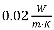


- In a preferred example, the inert gas flow may have a flow speed in the main flow direction may and that the mean flow speed measured 0.5cm over the opening is above 0.75m/s preferably above 1 m/s and/or below 4m/s preferably below 3 m/s even more preferred below 2.5m/s at 1013hPa. These boundaries may preferably be increased if the gas pressure in the volume of the process chamber is decreased and/or if the molar mass of the gas is decreased.
- In a preferred example, the process chamber comprises at least one oxygen sensor and/or a gas density sensor and/or thermal conductivity sensor and/or thermal capacity sensor configured to determine a value being representative for the thermal conductivity and/or thermal capacity, respectively of the inert gas. At least one of these sensors is preferably located in the bottom portion of the volume. For example, at least one of these sensors may be located on the bottom and/or in a recess of the bottom and/or below a distance of 5cm above the bottom and/or on the support and/or below the support, and/or at or within at least one of 10cm, 5cm, 2.5cm, 1cm, 0.5cm from the edge encircling the opening. In another example, at least one of these sensors is preferably located in the (first) inert gas outlet, preferably at the bottom of the (first) inert gas outlet and/or within at least one of 10cm, 5cm, 2.5cm, 1cm, 0.5cm from the edge encircling (first) inert gas outlet. Each of these example locations enable to measure the Oxygen concentration in the vicinity of the powder bed. Oxygen has a higher mass per molecule (16u) and will therefore accumulate in the bottom portion of the volume if He (4u) and/or Ne (10u) is used as inert gas (as usual, u is the unified atomic mass unit). Thus, potential leaks or impurities provided by the gas source can be detected quickly. Further the measurement is as representative as possible for the oxygen level right over the powder bed. In addition or alternatively, at least one of the sensors may be located in a duct connecting at least one inert gas outlet with at least one inert gas inlet.
- The at least one Oxygen sensor and/or a gas density sensor and/or thermal conductivity sensor and/or thermal capacity sensor is preferably located in the inertgas flow through the chamber. Particularly preferred is the respective sensor oriented at least essentially parallel to the inert gas flow, wherein at least essentially parallel indicates that parallel is preferred but that deviations within a few degrees (e.g., within ±30°, ±20°, ±10°, ±5°, ±2.5°, ±1° or 0°) can be accepted,
- The at least one Oxygen sensor and/or a gas density sensor is preferably coupled to a process chamber controlling device, i.e. to an electronic circuitry for controlling operation of the process chamber and/or an entire additive manufacturing apparatus with the process chamber (hereinafter simply "controller"). In particular if, e.g. the oxygen level is above a predefined threshold, the controller may increase the flow speed of the inert gas flow over the opening, e.g. by increasing the power provided to a vacuum pump being connected to the inert gas outlet and/or by opening a throttle valve upstream of the inert gas inlet. Further, prior to fusing the powder bed, the process chamber is preferably flooded with the inert gas. Once the oxygen level is below a predefined threshold the inert gas may be circulated from the inert gas outlet to the inert gas inlet using an inert gas pump to thereby establish the inert gas flow.
- In a preferred example, the process chamber may comprise a gas component concentration sensor being configured to measure a value being representative for at least one of the concentrations of O2, N2, He, Ne, Ar, Kr, Xe, Rn and/or for a ratio of at least two of these gases in the inert gas. The gas component sensor may be located or have a gas inlet at the positions indicated above for the oxygen sensor. The above referenced sensors can be considered as examples for a gas component concentration sensor. In other words, a gas component concentration sensor may be or comprise at least one of an Oxygen sensor and/or a gas density sensor and/or a thermal conductivity sensor and/or thermal capacity sensor and/or a gas chromatograph and/or a spectrometer and/or gas-analyzer, in particular He-analyzer. Further, it is noted that partial pressure values of O2, N2, He, Ne, Ar, Kr, Xe, Rn may be considered as representative for at least one of the concentrations of these gases if the total pressure is known. A simple and yet efficient way to measure concentrations is thus to measure the partial pressure of at least one of these gases, e.g. via the diffusion rate through a semipermeable membrane. For example, if a semipermeable membrane is permeable only for He, the diffusion rate through the membrane at a given differential pressure between the spaces being separated by the membrane can be used to determine the partial pressure of He in the inert gas.
- The gas component concentration sensor is preferably coupled to the process chamber controlling device by a data line. Hence, the values obtained by the gas component concentration sensor may be made available to the process chamber controlling device.
- In any embodiment the method my comprise feeding at least a portion of the inert gas being removed through the inert gas outlet via the inert gas inlet to the process chamber. This is as well referred to a recycling or circling the inert gas.
- A method for fusing at least a portion of the powder bed may thus comprise to control the composition of an inert gas flow being established above the powder bed.
- The method may comprise determining the concentration and/or partial pressure of at least one of O2, N2, He, Ne, Ar, Kr and Xe in the inert gas flow established above the powder by determining the concentration and/or partial pressure of at least one of O2, N2, He, Ne, Ar, Kr and Xe in the inert gas in the process chamber and/or being removed from the process chamber via the at least one inert gas outlet and/or being provided via the inert gas inlet to the process chamber. The method may further comprise obtaining a measurement value being representative for the concentration and/or partial pressure of at least one of O2, N2, He, Ne, Ar, Kr and Xe in the inert gas and comparing this measurement value with a lower limit and/or with an upper limit for the concentration and/or the partial pressure of the respective at least one of O2, N2, He, Ne, Ar, Kr and Xe in the inert gas. It is noted that O2 is not inert and hence should not be comprised in the inert gas. But monitoring the unintended O2-concentration may be used to increase the concentration(s) of inert components of the inert gas to thereby reduce the partial pressure and the concentration of the O2, what can be considered as effectively removing unintended O2 from the process chamber and hence the fusing process.
- In case said comparing provides that this measurement value is below a lower limit, the method may comprise adding the corresponding depleted component to the inert gas stream in the process chamber, e.g., by adding it to an inert gas stream circling from the inert gas outlet to the inert gas inlet and through the process chamber, while adding no or less of at least one other component of the inert gas mixture to the inert gas mixture. "less" in this context references to the amount of the depleted component, i.e. the amount added of the at least other component being added is less than the amount added of the depleted component.
- Similarly, in case said comparing provides that this measurement value is above an upper limit, the method may comprise adding the at least one other component to the inert gas in the process chamber, e.g. by adding it to an inert gas stream fed from the inert gas outlet via duct to the inert gas inlet (thereby into the process chamber) than said component having a measurement value above the upper limit, while adding no or less of said component having a measurement value above the upper limit. Similarly to the above "less" references to the amount the at least one other component is added. In other words more of the at least one other component is added than of the component having a measurement value above the upper limit.
- This method allows to partially and selectively replenish only those components of the inert gas that are underrepresented in a given composition as defined by the upper and lower boundaries for the respective components. This helps to keep operating costs low, while maintaining high workpiece quality. These method steps are based on the observation that for practical purposes the inert gas is often a mixture of essentially He and/or Ne with Ar and/or with N2 wherein the concentrations of He, Ne, Ar, and N2 in the mixture are well defined. However, He and Ne diffuse at a significantly higher rate through the duct wall and the other confining structures of the process chamber housing. The method thus allows to maintain the partial He and/or Ne-pressure and/or the He and/or Ne-concentration in the inert gas within given limits, while not replacing He and/or Ne-depleted inert gas from the process chamber by (costly) "fresh" inert gas. By measuring a value being representative for the, e.g., He and/or Ne-concentration (and/or partial pressure) and adding only He and/or Ne to the inert gas circling through the process chamber housing, if a He and/or Ne-depletion below the lower limit for He and/or Ne, respectively, has been observed. This approach can be used for any other of the inert gases mentioned above, i.e. curing a He and/or Ne-depletion is only a preferred example. Any other depletion can be resolved by adding the depleted component(s), preferably only.
- These steps of controlling the composition of an inert gas flow being established above the powder bed may be executed by the process chamber controlling device, as well referred to as "controller". In other words, the process chamber controlling device may be configured to execute the any of the above method steps, be it directly or by controlling and or communicating with corresponding components, like ,e.g., a gas component concentration sensor.
- The corresponding process chamber housing may thus comprise the process chamber controlling device. The process chamber controlling device may be connected to at least one gas component concentration sensor, e.g., via a data line and/or any other data transmission means. This gas component concentration sensor may be located in the process chamber. Alternatively or in addition, the (or another) gas component concentration sensor may be located at, attached to and/or integrated in a duct connecting the inert gas outlet with the inert gas inlet.
- The process chamber may further comprise an inert gas component source comprising only a component or a limited number of components of the inert gas in the process chamber. For example, the inert gas component source may comprise only He and/or Ne but no Ar or N2 if the inert gas is a mixture of all three gases. In practice it is sufficient if the concentration of the depleted inert gas component in the gas provided by the inert gas component source is greater than the preset or intended concentration of the depleted component in the inert gas, as in this case adding the gas mixture from the inert gas component source increases the concentration of component being depleted in the inert gas circling through the process chamber and the duct connecting the inert-gas outlet with the inert-gas inlet.
- The process chamber may also comprise more than one inert gas component sources, comprising respectively one different inert gas component and/or comprising different inert gas mixtures.
- As usual "limited number of components" means that at least one component of the (intended) inert gas mixture is not comprised or underrepresented in the inert gas component source. The inert gas component source may be fluidly connected via at least one inert gas component valve with the inert gas- inlet or with a separate gas inlet, e.g. via a branch of the duct. A fluid connection via the duct is preferred, as the concentrations of the components of the inert gas being provided to the process chamber homogenize. In other words, the inert gas in the process chamber has a more homogenous composition.
- The process chamber controlling device may be connected via e.g. at least one control line and/or a contactless data connection to the inert gas component valve, thereby being enabled to open and close the inert gas component valve.
- In another preferred example, the process chamber comprises a heater configured to heat the temperature of at least a portion of the inert gas flow through the process chamber to or above at least one of 25°C, 40°C, 60°C, 80°C, 100°C, 150°C, 250°C, 300°C, 350°C, 400°C, 450°C, 500°C, 600°C, 700°C, 800°C, 900°C, 1000°C.When using higher temperatures, the process chamber housing is preferably thermally isolated. By this increase of the gas temperature, the temperature gradient in a smoke plume is decreased and thus beam distortion of the smoke plume is reduced if not neglectable small.
- As already explained above, the process chamber preferably comprises a pressure controller, configured to maintain the pressure inside the process chamber below ambient pressure outside the process chamber and/or at or below at least one of 1000hPa, 900hPa, 800hPa, 700hPa, 600hPa, 500ha, 400hPa, 300hPa, 200hPa, 100hPa. The pressure controller may be integrated or form a part of a process chamber controller. In another preferred example, the pressure in the process chamber is above ambient pressure, thereby ensuring that no oxygen is sucked accidentally into the process chamber. In another example, the process chamber is enclosed in another housing, and the pressure in the process chamber is below ambient pressure, while the pressure in the volume being defined by the boundary of the process chamber and the another housing is above is above ambient pressure and in that the gas said volume is as well an inert gas, preferably the same as in the process chamber. This enables to ensure a lower pressure in the process chamber while at the same time reducing the risk that oxygen is accidentally sucked into the process chamber, because the volume between the boundary of the process chamber and the another housing is filled with an inert gas and has a pressure above ambient pressure.
- For example, the inert gas outlet may be in fluid communication with a low pressure inlet of a gas pump (e.g. a vacuum pump inlet) e.g. via the above mentioned duct and/or that the inert gas inlet may be in fluid communication with an inert gas source (e.g. the higher pressure gas outlet of the gas pump), wherein a throttle valve may be located upstream of the inert gas inlet. The optional pressure controller may be configured to increase and/or decrease the power provided to the gas pump. It may further be configured to open and/or close the throttle valve, e.g. by powering an actuator. The optional pressure controller may hence as well control the flow speed of the inert gas flow. The optional pressure controller may be connected to at least one pressure sensor and/or flow speed sensor and may control the pressure and/or the flow speed in the process chamber in response to signals being provided by at least one of the pressure sensor and/or the flow speed sensor.
- Changing the inert gas may have an impact of the signals being provided by flow speed and/or pressure sensors. This impact may require a recalibration of the sensors when changing the inert gas during manufacturing of a workpiece or between manufacturing of two workpieces. For example, when using an inert gas with an increased heat capacity and/or an increased thermal conductivity an anemometer for measuring the flow speed may require recalibration. For example, a hot wire anemometer experiences better cooling when increasing the thermal conductivity of the inert gas. Accordingly, the resistivity of the hot wire drops, which directly translates in presumably wrong flow speed readings, if the increased thermal conductivity is not considered. Similarly, a change of the (mean) molar mass and/or density of the inert gas may require a recalibration of the flow speed sensor, e.g., when using a vane anemometer or a cup anemometer.
- In a preferred example, the process chamber further comprises at least one second gas outlet in at least one of the bottom, the support, the opening walls and the opening bottom. The second gas outlet may be used when replacing a gas(mixture) like air by the inert gas, e.g. by at least one of He and/or Ne and/or Ar and/or N2, which may then preferably be provided to the volume via at least one second inert gas inlet in the ceiling. The use of expensive He and/or Ne or another inert gas can be reduced by each of these measures.
- The optional second gas outlet may be connected to a second gas outlet control valve, preferably to a check valve configured to disable gas flow into the process chamber via the second gas outlet. Further, the second gas outlet may be connected by a tube or the like to a gas inlet of a second outlet vacuum pump.
- As already apparent, the process chamber preferably comprises at least one (laser) beam entry window, which may be located above the support. In a particularly preferred example, the process chamber further comprises at least one inert gas jet stream inlet nozzle. As will be explained blow in more detail the term "Jetstream" used only to indicate that it is a second as well linguistically distinguishable gas stream flowing above the inert gas stream. The inert gas jet stream inlet nozzle is preferably positioned in the upper portion of the process chamber and is preferably oriented to provide an inert gas jet stream between the window and the support. Particularly preferred, the inert gas jet stream attaches to window surface and/or is directed downwards. This can be obtained by orienting the inert gas jet stream inlet nozzle accordingly, e.g. by orienting is towards the window surface and/or by use of the Coanda effect.
- Preferably opposite to the inert gas jet stream inlet nozzle may be at least one inert gas jet stream outlet nozzle, hence as well being positioned to provide an inert gas jet stream between the window and the support.
- The inert gas jet stream compensates for the effect that the smoke in a reduced density atmosphere tends to rise higher. The inert gas jet stream protects the window from being polluted by condensed or sublimated smoke, which as well would deteriorate beam quality and hence workpiece quality. The suggested measure thus enables to keep the vertical dimension of the volume reasonable, which reduces operating costs as well as installation costs and last but not least workpiece quality, as an increase in the distance between laser source and the powder decreases workpiece quality, as imperfections in beam focusing become more apparent.
- For example, the at least one inert gas jet stream inlet nozzle may have a nozzle outlet opening being oriented parallel within an angle αjs to the (first) inert gas inlet, wherein αjs ∈ A, and A = {30°, 20°, 10°, 5°, 2.5°, 1°, 0.5°, 0°}. This measure reduces turbulences in the volume and hence increases efficient smoke removal from the volume.
- Preferably, the flow speed of the inert gas jet stream relative to the window is at least 1.1, 1.25, 1.5, 2, 2.5, 3, 3.5, 4, 4. 5, 5, 7.5 and/or 10 times the flow speed of the inert gas flow 0.5cm over the opening. This increased flow speed thus provides for a flow speed gradient from the bottom to the ceiling. This gradient enables to safely remove the smoke without blowing powder from the powder bed towards inert gas outlet.
- In preferred example, the temperature of one the at least one optional inert gas jet stream is below the temperature of the main inert gas stream, at least measured at the corresponding nozzle openings. Residues in the smoke can thus condense prior to reaching the window and no or at least less residues in the smoke condense on the window.
- In another example, the temperature of one the at least one optional inert gas jet stream is above the temperature of the main inert gas stream, at least measured at the corresponding nozzle openings. This allows to efficiently cool the powder bed by the main inert gas flow flowing preferably at least almost directly over the powder bed. This can be obtained by positioning the lower edged of the (first) inert gas inlet and/or the lower edge of the (first) inert gas outlet at the height of the edge of the support opening and/or at the height of the bottom or slightly above these heights. Slightly above means within at least one of 0.5cm, 1cm, 1.5cm, 2cm and/or 2.5cm above the corresponding reference height. Further, the temperature of the main (first) inert gas flow from the (first) inert gas inlet to the (first) inert gas outlet is preferably below ambient temperature, e.g. at or below at least one of 23°C, 20°C, 18°C, 10°C, 0°, -5°C, - 10°C, -20°C. The lower the temperature, the better is the cooling, i.e. the heat transfer from the powder bed and/or the workpiece to the main inert gas stream. The temperature of the inert gas jet stream may be preferably at or above ambient temperature, e.g. at or above at least one of 25°C, 40°C, 60°C, 80°C, 100°C, 150°C, 250°C, 300°C, 350°C, 400°C, 450°C. This particularly preferred combination of having reduced temperature in the vicinity of the powder bed and an increased temperature above provides for both, a good cooling and low beam distortions.
- Further, it is preferred, if the vertical thickness of the main inert gas stream or flow is significantly smaller than the vertical thickness of the inert gas jet stream above the main inert gas stream. The vertical thickness of the respective streams can be controlled, e.g. by the vertical dimension of the respective inlet opening. Thus, the vertical dimension d 2 of the inert gas jet stream inlet is preferably greater or equal to x-times the vertical dimension d 1 of the (first) inert gas inlet, wherein x ∈ {1.5, 2, 2.5, 5, 10,15}, i.e. x · d 1 ≤ d 2.
- As apparent, both the main inert gas flow from the inert gas inlet nozzle to the inert gas outlet nozzle and the inert gas jet stream are "inert gas streams" the terms main inert gas stream and inert gas jet stream are used only to enable to linguistically distinguish these. Alternatively, one could have used first gas stream and second gas stream, but we consider the initially suggested wording to be more vivid. As apparent, in a preferred example the second inert gas stream (i.e. the inert gas jet stream) has a higher flow speed across the volume than the first (main) inert gas stream. The flow rate of the second inert gas stream may be higher than the first (=main) inert gas stream. Hence "main" does not have any implications regarding the amount of gas flowing per unit of time compared to other inert gas streams.
- An additive manufacturing apparatus according to the invention may of course comprise characterized in that it comprises the process chamber with at least one of the above explained features. In particular, the additive manufacturing apparatus may have one laser beam entry window and outside the process chamber, in front of the at least one window at least two (laser) beam sources each configured to emit at least one (laser) beam to a powder bed on top of the support. It is implicit that the window is at least essentially transparent for the beams being emitted by the (laser) beam sources through the at least one window towards the support. In a preferred example, the additive manufacturing apparatus is configured to scan a surface of a powder bed being below a smoke plume being produced by operation of a first (laser) beam source. This measure even allows to increase workpiece quality, e.g. by optimizing the thermal stress to the workpiece during manufacturing.
- In the following, the invention will be described by way of example, without limitation of the general inventive concept, on examples of embodiment with reference to the drawing.
-
Figure 1 shows an example process chamber of an additive manufacturing apparatus. -
Figure 2 shows another example process chamber of an additive manufacturing apparatus. - In
figure 1 is a simplified sectional view of an example additive manufacturing apparatus 1 with aprocess chamber 5. Theprocess chamber 5 has avolume 51 being enclosed byside walls ceiling 10 and abottom 9. Thebottom 9 has anopening 94 with openingwalls 93. The openingwalls 93 may provide a linear bearing for a movably supportedsupport 8, which can be lowered and raised. On top of thesupport 8 may be anoptional powder bed 99 in which a partially manufactured workpiece 4 may be embedded. Thepowder bed 99 and the workpiece 4 are depicted only as an example, but the additive manufacturing apparatus 1 and/or theprocess chamber 5 are/is typically delivered without any powder bed or workpiece. - The
ceiling 10 haswindows beams beam sources first beam source 80 and asecond beam source 90 emitting the first and thesecond beam process chamber 5 has more than twobeam sources window opening 94 in the bottom. - An (first)
inert gas inlet 6 in afront side wall 11 and an (first) inert gas outlet 7 in arear side wall 12 enable to provide a maininert gas flow 20 across theopening 94 in thebottom 9, i.e. in a main inertgas flow direction 2. As can be seen, the maininert gas flow 20 may flow at least essentially parallel (i.e. ±αms (αms ∈ {30°, 20°, 10°, 5°, 2.5°, 1°, 0.5°, 0°}) to thebottom 9 and hence at least essentially parallel to the powder bed surface and the powder bed supporting surface of thesupport 8. In the depicted example, the main inertgas flow direction 2 has a small downward component. Preferably, the inert gas comprises at least 20% Helium (He), and/or has a density below 1.4kg/cm and/or a temperature above the dew point of the gas. In an example the pressure may be at or above ambient pressure. In another example the pressure may be at or below ambient pressure. - Above the main
inert gas inlet 6 is at least one optional secondinert gas inlet 256 and at least one optional thirdinert gas outlets 266. Above the main inert gas outlet 7 is at least one optional secondinert gas outlet 257. These could as well be referred to an inert gas jet stream inlets or inert gas jet stream outlets, respectively. - In operation, a second inert gas stream may flow above the main (first) inert gas stream from the at least one optional second
inert gas inlet 256 to the at least one optional secondinert gas outlet 257. As indicated by thearrows 25, the volume per amount of time, i.e. the flow rate and/or the flow speed of the optional secondinert gas flow 25 are/is preferably higher than the flow rate, and/or the flow speed, respectively of the maininert gas flow 20. Further, the downward component of the flow direction of the second inertgas flow direction 252 is preferably greater than the downward component of main inertgas flow direction 2. The temperature of the secondinert gas flow 25 is preferably below the temperature of the maininert gas flow 20. - The optional third
inert gas inlet 266 is preferably located in the vicinity (within 10cm, 5cm, 2.5cm and/or 1cm) of the at least onewindow ceiling 10 and located to attach a third inert gas stream to the surface of the at least onewindow window volume 51 via the at least one secondinert gas inlet 256. - As indicated, each of the
beams powder bed 99 and the fusing process produces first and asecond smoke plumes second beam 91 passes through thefirst smoke plume 82 originating from the interaction of thefirst beam 81 with thepowder bed 99. - The inert gas is removed by at least one
pump 32, i.e. the first and secondinert gas outlets 7, 257 are in fluid communication with the lower pressure inlet of thegas pump 32 which then feeds the inert gas to at least one of theinert gas inlets duct 33. The temperature of the different inert gas streams can be controlled preferably by optionalindirect heat exchangers - A
controller 3 may be connected by data and/or power lines to thebeam sources pump 32, valves 38, etc. Example connections are indicated by dashed or dotted arrows. -
Figure 2 shows another simplified sectional view of an example additive manufacturing apparatus 1 with aprocess chamber 5. The description offigure 1 can as well be read onfigure 2 . Only differences will be explained herein. Similar tofigure 1 , at least one of theinert gas outlets 7 and 257 of theprocess chamber 5 may be connected via aduct 33 with at least one of theinert gas inlets pump 32 may have a pump inlet being in fluid communication with at least one of theinert gas outlets inert gas inlets duct 33. The duct may comprise agas component sensor 30. The values measured by thegas component sensors 30, regardless of its position, may be provided to thecontroller 3 by some data line or any other communication means. The controller may as well be referred to as processchamber controlling device 3. - The process chamber housing preferably has at least one of these
gas component sensors 30. InFig. 2 , twogas component sensors 30 are depicted at preferred positions for illustrative purposes. Other numbers of gas composition sensors can be used as well. - The process chamber housing may further comprise at least one inert
gas component source 34. In an example, the inertgas component source 34 may comprise a tank being filled or configured to be filled with, e.g., He and/or Ne or another inert gas or inert gas mixture. - The inert
gas component source 34 is fluidly connected via an inertgas component valve 26 with at least one of theinert gas inlets - The
controller 3 is preferably configured to monitor based on at least one measured value the concentration and/or or partial pressure of at least one of He and Ne in the inert gas in theprocess chamber 5 and/or theduct 33. Such measurement values can be retrieved from at least one of the at least one inertgas component sensors 30. If the concentration of He and Ne in the inert gas in theprocess chamber 5 depletes below a predefined lower limit, the controller may be configured to open the inertgas component valve 36, e.g. for a given duration. The duration may be calculated, e.g. based on the difference between the lower limit and the measured value. By opening the inertgas component valve 36, the depleted inert gas component may be provided to the inert gas being provided to the process chamber. Thereby, the concentration of the depleted component, in this example He and/or Ne can be corrected. Similarly, if a measured concentration of another component of the inert gas in theprocess chamber 5 and/or the duct is above an upper limit, the controller may open the inertgas component valve 36 to thereby reduce the concentration of the component having a concentration above its upper limit. The process chamber may have a number of inertgas component sources 34 being filled with different inert gases and corresponding inertgas component valves 36 to selectively replenish a depleted inert gas component. -
- 1
- additive manufacturing apparatus
- 2
- main inert gas flow direction
- 3
- controller / process chamber controlling device
- 4
- workpiece / adhered moieties of raw material
- 5
- process chamber
- 6
- gas inlet
- 7
- gas outlet
- 8
- support
- 9
- bottom
- 10
- ceiling
- 101
- window
- 102
- window
- 11
- first sidewall
- 12
- second sidewall
- 13
- third sidewall
- 20
- main inert gas flow
- 201
- heat exchanger
- 25
- second inert gas flow (inert gas jet stream flow)
- 251
- heat exchanger
- 252
- direction of second inert gas flow
- 256
- second inert gas inlet
- 257
- second inert gas outlet
- 26
- third inert gas flow
- 261
- heat exchanger
- 266
- third inert gas inlet
- 30
- gas component sensor, e.g. oxygen sensor and/or a gas density sensor and/or gas component concentration sensor,
- 32
- pump
- 33
- duct
- 34
- inert gas component source
- 35
- heater
- 36
- inert gas component valve
- 50
- recoater
- 80
- first beam source
- 81
- first beam / first laser beam
- 82
- first smoke plume
- 90
- second beam source
- 91
- first beam / first laser beam
- 92
- second smoke plume
- 93
- opening walls
- 94
- support opening in
bottom 9, configured to receivesupport 8 - 99
- powder bed
Claims (15)
- An additive manufacturing apparatus comprising:at least a first beam source (80) configured to emit at least a first beam (81),at least a second beam source (90) configured to emit at least a second beam (91), anda process chamber housing (1),wherein the process chamber housing (1) comprises a process chamber (5),wherein the process chamber (5) has at least:- a bottom (9), a ceiling (10) and side walls (11, 12, 13), jointly enclosing a volume (51) of the process chamber (5),- an inert gas inlet (6) configured to provide an inert gas into the process chamber (5),- an inert gas outlet (7) configured to release the inert gas out of the process chamber (5),wherein the bottom (9) has an opening (94), being delimited by opening walls (93) and a vertically movable support (8) for supporting a powder bed (99) and a three dimensional object (4) located in between of the opening walls (93), andwherein the gas inlet (6) is configured to provide a light inert gas, having a density of less than 1,4 kg/m3, into the process chamber (5),characterized in thatthe additive manufacturing apparatus further comprises a process chamber controlling device (3) configured to control the additive manufacturing apparatus to execute the step of fusing at least- a first location of the powder bed (99) using the first beam (81), thereby generating a first smoke plume (82), and- a second location of the powder bed (99) using the second beam (91), thereby generating a second smoke plume (92),wherein the first location is closer to the inert gas inlet (6) than the second location and the second location is closer to the inert gas outlet (7) than the first location,while the at least one second beam (91) is controlled to fuse the second location of the powder bed (99) being covered by the first smoke plume (82) being generated by fusing the first location of the powder bed (99) with the at least one first beam (81), and in thatthe inert gas inlet (6) and the inert gas outlet (7) are configured to remove the smoke plumes (82, 92) from the process chamber (5) by a main inert gas flow, wherein the main inert gas flow is established by an inert gas comprising at least 20% of He and/or Ne.
- The additive manufacturing apparatus of claim 1, characterized in that- the inert gas inlet (6) and the inert gas outlet (7) are positioned at opposite sides of the process chamber and/or the opening (94), thereby being configured establish an inert gas flow (2) in a main flow direction (2) from the inert gas inlet (6) over the opening (94), to the inert gas outlet (7).
- The additive manufacturing apparatus of at least one of the previous claims, characterized in, that
the inert gas flow in the main flow direction (2) has a flow speed and that the mean flow speed measured 0.5cm over the opening (94) is:- above 0.75m/s, and/or- below 4 m/s - The additive manufacturing apparatus of at least one of the previous claims, characterized in that
the process chamber (5) comprises at least one gas component concentration sensor, wherein at least one of the at least one gas component concentration sensor (30) is located- on the bottom, and/or- in a recess of the bottom, and/or- below a distance of 5cm above the bottom, and/or- on the support and/or below the support, and/or- at or within at least one of 10cm, 5cm, 2.5cm, 1cm, 0.5cm from an edge in the bottom encircling the opening (94), and/or- in a duct 33 connecting the inert gas outlet (7) with the inert gas inlet (6). - The additive manufacturing apparatus of at least claim 4, characterized in that the process chamber housing further comprises at least one inert gas component source (34) being fluidly connected via an inert gas component valve (36) with the inert gas inlet (6) of the process chamber (5).
- The additive manufacturing apparatus of at least one of the previous claims, characterized in that- the process chamber (5) comprises a heater (35) configured to heat the temperature of at least a portion of the inert gas flow through the process chamber to or above at least one of 25°C, 40°C, 60°C, 80°C, 100°C, 150°C, 250°C, 300°C, 350°C, 400°C, 450°C.
- The additive manufacturing apparatus of one of the previous claims, characterized in that
the inert gas outlet (7) is in fluid communication with a vacuum pump and/or in that the inert gas inlet (6) is in fluid communication with an inert gas source, wherein a throttle valve is located upstream of the inert gas inlet. - The additive manufacturing apparatus of at least one of the previous claims, characterized in that the process chamber further comprises:- at least one second gas outlet in at least one of the bottom, the support, the opening walls and the opening bottom and/or- at least one second inert gas inlet in the ceiling.
- The additive manufacturing apparatus of claim 8, characterized in that- the second gas outlet is connected to a second gas outlet control valve, preferably to a check valve configured to disable gas flow into the process chamber via the second gas outlet and/or- the second gas outlet is connected to the gas inlet of a second outlet vacuum pump.
- The additive manufacturing apparatus of at least one of the previous claims, characterized in that the process chamber housing (1) further comprises at least one beam entry window located above the opening (94) and optionally- at least one inert gas jetstream inlet nozzle, positioned to provide an inert gas jet stream between the window and the support and/or- at least one inert gas jetstream outlet nozzle, positioned to provide an inert gas jet stream between the window and the support.
- The additive manufacturing apparatus of at least claim 10, characterized in that the at least one inert gas jet stream inlet nozzle has a nozzle outlet opening being oriented parallel within an angle αjs to the inert gas inlet, wherein αjs ∈ A, and A = {30°, 20°, 10°, 5°, 2.5°, 1°, 0.5°, 0°}
- The additive manufacturing apparatus of at least claim 10 or 11, characterized in that- at least two beam sources of the additive manufacturing apparatus are arranged in front of the at least one beam entry window, outside of the process chamber (5), the at least two beam sources each being configured to emit at least one beam to a powder bed (99) on top of the support (8).
- A method for fusing at least a portion of a layer of a powder bed (99) comprising at least:- emitting at least two different beams (81, 91) from at least two different beam sources (80, 90) onto at least two different locations of the powder bed (99), each beam producing a smoke plume (82, 92), and- removing the smoke plumes (82, 92)by establishing a main inert gas flow from an inert gas inlet (6) to an inert gas outlet (7), the main inert gas flow having a direction with a component being parallel to the powder bed, wherein a first location being hit by a first beam (81) from a first beam source (80) is closer to the inert gas inlet (6) than a second location being hit by a second beam (91) from a second beam source (90) and the second location is closer to the inert gas outlet (7) than the first location,- fusing the second location of the powder bed (99) by the second beam (91) from the second beam source (90) while at least a portion of the first smoke plume (82) is between the second beam source (90) and the second location, wherein
the density of the inert gas flow is at or below 1.4 kg/m3 at normal conditions and/or at the conditions with a distance of 20mm above the layer, and wherein the main inert gas flow is established by an inert gas comprising at least 20% of He and/or Ne. - The method of claim 13, characterized in that- the method further comprises the step of providing the additive manufacturing apparatus of any of claims 1 to 12; and/or in that- the distance between the first location and the second location is smaller than at least one of 100mm, 70mm, 40mm, 30mm, 20mm and 10mm; and/or in that- the distance between the first location and the second location is smaller than at least one of 100mm, 70mm, 40mm, 30mm, 20mm, 10mm, wherein the temporal distance between the moments when the first and second beams are emitted to said first location and said second location is smaller than at least one of 10%, 20%, 30%, 40%, 50%, 60%, 70% and 80% of the maximum time span during which the first beam (81) or the second beam (91) is emitted onto the layer, and/or in that- the established inert gas flow comprises at least one of 20%, 30%, 40%, 50%, 60%, 70%, 80%, 90%, 95%, 98%, 99% He, wherein the percentage relates to the amount mol He and/or Ne relative to the total amount of gas.
- The method of one of claims 13 to 14, characterized in that the established inert gas flow has a temperature at or above at least one of 25°C, 40°C, 60°C, 80°C, 100°C, 150°C, 250°C, 300°C, 350°C, 400°C, 450°C.
Priority Applications (1)
| Application Number | Priority Date | Filing Date | Title |
|---|---|---|---|
| EP25169196.0A EP4603214A1 (en) | 2021-05-07 | 2022-05-03 | Process chamber for an additive manufacturing apparatus and method for operating the process chamber |
Applications Claiming Priority (2)
| Application Number | Priority Date | Filing Date | Title |
|---|---|---|---|
| DE102021111964 | 2021-05-07 | ||
| PCT/EP2022/061835 WO2022233860A1 (en) | 2021-05-07 | 2022-05-03 | Process chamber for an additive manufacturing apparatus and method for operating the process chamber |
Related Child Applications (2)
| Application Number | Title | Priority Date | Filing Date |
|---|---|---|---|
| EP25169196.0A Division-Into EP4603214A1 (en) | 2021-05-07 | 2022-05-03 | Process chamber for an additive manufacturing apparatus and method for operating the process chamber |
| EP25169196.0A Division EP4603214A1 (en) | 2021-05-07 | 2022-05-03 | Process chamber for an additive manufacturing apparatus and method for operating the process chamber |
Publications (3)
| Publication Number | Publication Date |
|---|---|
| EP4334060A1 EP4334060A1 (en) | 2024-03-13 |
| EP4334060B1 true EP4334060B1 (en) | 2025-06-04 |
| EP4334060C0 EP4334060C0 (en) | 2025-06-04 |
Family
ID=81940641
Family Applications (2)
| Application Number | Title | Priority Date | Filing Date |
|---|---|---|---|
| EP22727793.6A Active EP4334060B1 (en) | 2021-05-07 | 2022-05-03 | Process chamber for an additive manufacturing apparatus and method for operating the process chamber |
| EP25169196.0A Pending EP4603214A1 (en) | 2021-05-07 | 2022-05-03 | Process chamber for an additive manufacturing apparatus and method for operating the process chamber |
Family Applications After (1)
| Application Number | Title | Priority Date | Filing Date |
|---|---|---|---|
| EP25169196.0A Pending EP4603214A1 (en) | 2021-05-07 | 2022-05-03 | Process chamber for an additive manufacturing apparatus and method for operating the process chamber |
Country Status (4)
| Country | Link |
|---|---|
| US (1) | US20240157648A1 (en) |
| EP (2) | EP4334060B1 (en) |
| CN (1) | CN117320827A (en) |
| WO (1) | WO2022233860A1 (en) |
Families Citing this family (5)
| Publication number | Priority date | Publication date | Assignee | Title |
|---|---|---|---|---|
| FR3143416B1 (en) * | 2022-12-14 | 2025-03-14 | Addup | Device and method for additive manufacturing with a protective gas flow of an optical access window. |
| US20250282094A1 (en) * | 2024-03-05 | 2025-09-11 | Dmg Mori Co., Ltd. | Z-axis leveling |
| CN117884655B (en) * | 2024-03-14 | 2024-07-23 | 中国海洋大学 | 3D printer and control method thereof |
| US20260061532A1 (en) * | 2024-08-30 | 2026-03-05 | Rtx Corporation | Apparatus and related method(s) for repairing machine parts |
| DE102024124990A1 (en) * | 2024-09-02 | 2026-03-05 | TRUMPF Laser- und Systemtechnik SE | Build chamber for providing a protective gas flow in an additive manufacturing device and additive manufacturing device |
Citations (6)
| Publication number | Priority date | Publication date | Assignee | Title |
|---|---|---|---|---|
| WO2016102970A1 (en) * | 2014-12-23 | 2016-06-30 | Renishaw Plc | Additive manufacturing apparatus and methods |
| DE102018128543A1 (en) * | 2017-11-17 | 2019-05-23 | Sodick Co. Ltd. | Three-dimensional printer |
| US20190232429A1 (en) * | 2018-02-01 | 2019-08-01 | Velo3D, Inc. | Three-dimensional printing |
| US20200031054A1 (en) * | 2018-07-27 | 2020-01-30 | Concept Laser Gmbh | Apparatus for additively manufacturing three-dimensional objects |
| EP3797903A1 (en) * | 2019-09-25 | 2021-03-31 | Linde GmbH | Additive manufacturing process gas for lightweight metals |
| US20210114109A1 (en) * | 2018-09-25 | 2021-04-22 | Linde Gmbh | Method and device for feeding gas to an additive manufacturing space |
Family Cites Families (22)
| Publication number | Priority date | Publication date | Assignee | Title |
|---|---|---|---|---|
| EP1234625A1 (en) * | 2001-02-21 | 2002-08-28 | Trumpf Werkzeugmaschinen GmbH + Co. KG | Process and apparatus for producing a shaped body by selective laser sintering |
| WO2004076102A1 (en) * | 2003-02-25 | 2004-09-10 | Matsushita Electric Works, Ltd. | Three dimensional structure producing device and producing method |
| DE102006056422B3 (en) | 2006-11-28 | 2008-04-17 | Cl Schutzrechtsverwaltungs Gmbh | Coating or compensating arrangement for a building device for forming molded parts for a laser sintering installation comprises a two-piece blade unit consisting of a connecting body and an end piece impinging a building material |
| GB0816308D0 (en) * | 2008-09-05 | 2008-10-15 | Mtt Technologies Ltd | Optical module |
| EP2590781A1 (en) | 2010-07-09 | 2013-05-15 | Eltronic A/S | Abrading arrangement to abrade a surface of an item and method of use thereof |
| CA2900297A1 (en) * | 2013-03-15 | 2014-09-18 | Matterfab Corp. | Cartridge for an additive manufacturing apparatus and method |
| CN105579218B (en) * | 2013-03-15 | 2018-09-18 | 3D系统公司 | Improved powder for laser sintering system distributes |
| JP5893112B1 (en) * | 2014-10-06 | 2016-03-23 | 株式会社ソディック | Additive manufacturing equipment |
| GB201418595D0 (en) * | 2014-10-20 | 2014-12-03 | Renishaw Plc | Additive manufacturing apparatus and methods |
| DE102014016679A1 (en) | 2014-11-12 | 2016-05-12 | Cl Schutzrechtsverwaltungs Gmbh | Method and device for exposure control of a selective laser sintering or laser melting device |
| WO2017143145A1 (en) | 2016-02-17 | 2017-08-24 | UCT Additive Manufacturing Center Pte. Ltd. | Multi-blade recoater |
| JP6651620B2 (en) * | 2016-05-31 | 2020-02-19 | 株式会社日立製作所 | Additive manufacturing equipment |
| EP3321003B1 (en) | 2016-11-11 | 2019-01-09 | SLM Solutions Group AG | Apparatus and method for producing a three-dimensional work piece with improved gas flow |
| US20180178285A1 (en) * | 2016-12-23 | 2018-06-28 | General Electric Company | Method for controlling plume trajectories in additive manufacturing |
| US11072025B2 (en) * | 2016-12-23 | 2021-07-27 | General Electric Company | Method for avoiding plume interference in additive manufacturing |
| US20180186080A1 (en) * | 2017-01-05 | 2018-07-05 | Velo3D, Inc. | Optics in three-dimensional printing |
| US10646924B2 (en) | 2017-02-21 | 2020-05-12 | General Electric Company | Additive manufacturing using a recoater with in situ exchangeable recoater blades |
| JP7199173B2 (en) * | 2018-07-23 | 2023-01-05 | 三菱重工業株式会社 | Additive manufacturing equipment |
| EP3628420A1 (en) | 2018-09-25 | 2020-04-01 | Linde Aktiengesellschaft | Method, gas and device for additive manufacturing |
| EP3670031A1 (en) | 2018-12-19 | 2020-06-24 | Linde GmbH | Method and system for generating a three-dimensional workpiece |
| WO2020178216A1 (en) | 2019-03-04 | 2020-09-10 | SLM Solutions Group AG | Control method, control device and production apparatus |
| DE112019007022B4 (en) * | 2019-04-16 | 2023-03-30 | Mitsubishi Electric Corporation | Metal forming shield gas nozzle and laser metal forming device |
-
2022
- 2022-05-03 CN CN202280033564.8A patent/CN117320827A/en active Pending
- 2022-05-03 EP EP22727793.6A patent/EP4334060B1/en active Active
- 2022-05-03 WO PCT/EP2022/061835 patent/WO2022233860A1/en not_active Ceased
- 2022-05-03 EP EP25169196.0A patent/EP4603214A1/en active Pending
-
2023
- 2023-11-06 US US18/502,639 patent/US20240157648A1/en active Pending
Patent Citations (6)
| Publication number | Priority date | Publication date | Assignee | Title |
|---|---|---|---|---|
| WO2016102970A1 (en) * | 2014-12-23 | 2016-06-30 | Renishaw Plc | Additive manufacturing apparatus and methods |
| DE102018128543A1 (en) * | 2017-11-17 | 2019-05-23 | Sodick Co. Ltd. | Three-dimensional printer |
| US20190232429A1 (en) * | 2018-02-01 | 2019-08-01 | Velo3D, Inc. | Three-dimensional printing |
| US20200031054A1 (en) * | 2018-07-27 | 2020-01-30 | Concept Laser Gmbh | Apparatus for additively manufacturing three-dimensional objects |
| US20210114109A1 (en) * | 2018-09-25 | 2021-04-22 | Linde Gmbh | Method and device for feeding gas to an additive manufacturing space |
| EP3797903A1 (en) * | 2019-09-25 | 2021-03-31 | Linde GmbH | Additive manufacturing process gas for lightweight metals |
Also Published As
| Publication number | Publication date |
|---|---|
| US20240157648A1 (en) | 2024-05-16 |
| CN117320827A (en) | 2023-12-29 |
| WO2022233860A1 (en) | 2022-11-10 |
| EP4603214A1 (en) | 2025-08-20 |
| EP4334060C0 (en) | 2025-06-04 |
| EP4334060A1 (en) | 2024-03-13 |
| JP2024518663A (en) | 2024-05-01 |
Similar Documents
| Publication | Publication Date | Title |
|---|---|---|
| EP4603214A1 (en) | Process chamber for an additive manufacturing apparatus and method for operating the process chamber | |
| US11278965B2 (en) | Apparatus for producing a three-dimensional work piece with improved gas flow | |
| US10682701B2 (en) | Apparatus for producing a three-dimensional work piece with improved gas flow | |
| JP5324917B2 (en) | Method and device for manufacturing a three-dimensional object in a 3D generation process | |
| ES2627079T3 (en) | Reactor for the production of an object of a weldable material, namely titanium | |
| EP3856437B1 (en) | Method and device for feeding gas to an additive manufacturing space | |
| WO2018197888A1 (en) | Powder bed fusion apparatus and methods | |
| EP2535137B1 (en) | Apparatus for and method of providing an inerting gas during soldering | |
| US10994332B2 (en) | Lamination molding apparatus | |
| EP3558636B1 (en) | Method for controlling plume trajectories in additive manufacturing | |
| EP3628420A1 (en) | Method, gas and device for additive manufacturing | |
| TWI712459B (en) | Lamination molding apparatus | |
| TW201735086A (en) | Liquid target X-ray source with jet mixing tool | |
| WO2021058134A1 (en) | Additive manufacturing process gas for lightweight metals | |
| US6365905B1 (en) | Focused ion beam processing apparatus | |
| JP6283053B2 (en) | Additive manufacturing equipment | |
| EP3292927A1 (en) | Method for additive manufacturing | |
| US20230025007A1 (en) | Active air conditioning in slm processes | |
| KR100841478B1 (en) | Liquid target supply device capable of mounting multiple capillaries and X-ray and extreme ultraviolet light source generators | |
| JP2009168560A (en) | Protective film forming method and sample cross-sectional observation method | |
| CN121013774A (en) | Scanner system used in apparatus for producing three-dimensional workpieces | |
| JP2026504341A (en) | Apparatus and method for manufacturing three-dimensional workpieces | |
| KR20250140296A (en) | Substrate processing apparatus |
Legal Events
| Date | Code | Title | Description |
|---|---|---|---|
| STAA | Information on the status of an ep patent application or granted ep patent |
Free format text: STATUS: UNKNOWN |
|
| STAA | Information on the status of an ep patent application or granted ep patent |
Free format text: STATUS: THE INTERNATIONAL PUBLICATION HAS BEEN MADE |
|
| PUAI | Public reference made under article 153(3) epc to a published international application that has entered the european phase |
Free format text: ORIGINAL CODE: 0009012 |
|
| STAA | Information on the status of an ep patent application or granted ep patent |
Free format text: STATUS: REQUEST FOR EXAMINATION WAS MADE |
|
| 17P | Request for examination filed |
Effective date: 20231206 |
|
| AK | Designated contracting states |
Kind code of ref document: A1 Designated state(s): AL AT BE BG CH CY CZ DE DK EE ES FI FR GB GR HR HU IE IS IT LI LT LU LV MC MK MT NL NO PL PT RO RS SE SI SK SM TR |
|
| STAA | Information on the status of an ep patent application or granted ep patent |
Free format text: STATUS: EXAMINATION IS IN PROGRESS |
|
| 17Q | First examination report despatched |
Effective date: 20240529 |
|
| DAV | Request for validation of the european patent (deleted) | ||
| DAX | Request for extension of the european patent (deleted) | ||
| GRAP | Despatch of communication of intention to grant a patent |
Free format text: ORIGINAL CODE: EPIDOSNIGR1 |
|
| STAA | Information on the status of an ep patent application or granted ep patent |
Free format text: STATUS: GRANT OF PATENT IS INTENDED |
|
| INTG | Intention to grant announced |
Effective date: 20250212 |
|
| GRAS | Grant fee paid |
Free format text: ORIGINAL CODE: EPIDOSNIGR3 |
|
| GRAA | (expected) grant |
Free format text: ORIGINAL CODE: 0009210 |
|
| STAA | Information on the status of an ep patent application or granted ep patent |
Free format text: STATUS: THE PATENT HAS BEEN GRANTED |
|
| AK | Designated contracting states |
Kind code of ref document: B1 Designated state(s): AL AT BE BG CH CY CZ DE DK EE ES FI FR GB GR HR HU IE IS IT LI LT LU LV MC MK MT NL NO PL PT RO RS SE SI SK SM TR |
|
| REG | Reference to a national code |
Ref country code: GB Ref legal event code: FG4D |
|
| REG | Reference to a national code |
Ref country code: CH Ref legal event code: EP |
|
| REG | Reference to a national code |
Ref country code: DE Ref legal event code: R096 Ref document number: 602022015551 Country of ref document: DE |
|
| REG | Reference to a national code |
Ref country code: IE Ref legal event code: FG4D |
|
| U01 | Request for unitary effect filed |
Effective date: 20250623 |
|
| U07 | Unitary effect registered |
Designated state(s): AT BE BG DE DK EE FI FR IT LT LU LV MT NL PT RO SE SI Effective date: 20250701 |
|
| PG25 | Lapsed in a contracting state [announced via postgrant information from national office to epo] |
Ref country code: ES Free format text: LAPSE BECAUSE OF FAILURE TO SUBMIT A TRANSLATION OF THE DESCRIPTION OR TO PAY THE FEE WITHIN THE PRESCRIBED TIME-LIMIT Effective date: 20250604 |
|
| PG25 | Lapsed in a contracting state [announced via postgrant information from national office to epo] |
Ref country code: GR Free format text: LAPSE BECAUSE OF FAILURE TO SUBMIT A TRANSLATION OF THE DESCRIPTION OR TO PAY THE FEE WITHIN THE PRESCRIBED TIME-LIMIT Effective date: 20250905 Ref country code: NO Free format text: LAPSE BECAUSE OF FAILURE TO SUBMIT A TRANSLATION OF THE DESCRIPTION OR TO PAY THE FEE WITHIN THE PRESCRIBED TIME-LIMIT Effective date: 20250904 |
|
| PG25 | Lapsed in a contracting state [announced via postgrant information from national office to epo] |
Ref country code: PL Free format text: LAPSE BECAUSE OF FAILURE TO SUBMIT A TRANSLATION OF THE DESCRIPTION OR TO PAY THE FEE WITHIN THE PRESCRIBED TIME-LIMIT Effective date: 20250604 |
|
| PG25 | Lapsed in a contracting state [announced via postgrant information from national office to epo] |
Ref country code: HR Free format text: LAPSE BECAUSE OF FAILURE TO SUBMIT A TRANSLATION OF THE DESCRIPTION OR TO PAY THE FEE WITHIN THE PRESCRIBED TIME-LIMIT Effective date: 20250604 |
|
| PG25 | Lapsed in a contracting state [announced via postgrant information from national office to epo] |
Ref country code: RS Free format text: LAPSE BECAUSE OF FAILURE TO SUBMIT A TRANSLATION OF THE DESCRIPTION OR TO PAY THE FEE WITHIN THE PRESCRIBED TIME-LIMIT Effective date: 20250904 |
|
| PG25 | Lapsed in a contracting state [announced via postgrant information from national office to epo] |
Ref country code: IS Free format text: LAPSE BECAUSE OF FAILURE TO SUBMIT A TRANSLATION OF THE DESCRIPTION OR TO PAY THE FEE WITHIN THE PRESCRIBED TIME-LIMIT Effective date: 20251004 |
|
| PG25 | Lapsed in a contracting state [announced via postgrant information from national office to epo] |
Ref country code: SM Free format text: LAPSE BECAUSE OF FAILURE TO SUBMIT A TRANSLATION OF THE DESCRIPTION OR TO PAY THE FEE WITHIN THE PRESCRIBED TIME-LIMIT Effective date: 20250604 |
|
| PG25 | Lapsed in a contracting state [announced via postgrant information from national office to epo] |
Ref country code: CZ Free format text: LAPSE BECAUSE OF FAILURE TO SUBMIT A TRANSLATION OF THE DESCRIPTION OR TO PAY THE FEE WITHIN THE PRESCRIBED TIME-LIMIT Effective date: 20250604 |
|
| PG25 | Lapsed in a contracting state [announced via postgrant information from national office to epo] |
Ref country code: SK Free format text: LAPSE BECAUSE OF FAILURE TO SUBMIT A TRANSLATION OF THE DESCRIPTION OR TO PAY THE FEE WITHIN THE PRESCRIBED TIME-LIMIT Effective date: 20250604 |
|
| PLBE | No opposition filed within time limit |
Free format text: ORIGINAL CODE: 0009261 |
|
| STAA | Information on the status of an ep patent application or granted ep patent |
Free format text: STATUS: NO OPPOSITION FILED WITHIN TIME LIMIT |
|
| REG | Reference to a national code |
Ref country code: CH Ref legal event code: L10 Free format text: ST27 STATUS EVENT CODE: U-0-0-L10-L00 (AS PROVIDED BY THE NATIONAL OFFICE) Effective date: 20260416 |
|
| 26N | No opposition filed |
Effective date: 20260305 |
|
| U20 | Renewal fee for the european patent with unitary effect paid |
Year of fee payment: 5 Effective date: 20260525 |
|
| PGFP | Annual fee paid to national office [announced via postgrant information from national office to epo] |
Ref country code: GB Payment date: 20260521 Year of fee payment: 5 |