EP4333462A1 - Speaker and acoustic device using speaker - Google Patents
Speaker and acoustic device using speaker Download PDFInfo
- Publication number
- EP4333462A1 EP4333462A1 EP23193511.5A EP23193511A EP4333462A1 EP 4333462 A1 EP4333462 A1 EP 4333462A1 EP 23193511 A EP23193511 A EP 23193511A EP 4333462 A1 EP4333462 A1 EP 4333462A1
- Authority
- EP
- European Patent Office
- Prior art keywords
- diaphragm
- edge
- frame
- speaker
- edge member
- Prior art date
- Legal status (The legal status is an assumption and is not a legal conclusion. Google has not performed a legal analysis and makes no representation as to the accuracy of the status listed.)
- Pending
Links
Images



Classifications
-
- H—ELECTRICITY
- H04—ELECTRIC COMMUNICATION TECHNIQUE
- H04R—LOUDSPEAKERS, MICROPHONES, GRAMOPHONE PICK-UPS OR LIKE ACOUSTIC ELECTROMECHANICAL TRANSDUCERS; ELECTRIC HEARING AIDS; PUBLIC ADDRESS SYSTEMS
- H04R7/00—Diaphragms for electromechanical transducers; Cones
- H04R7/16—Mounting or tensioning of diaphragms or cones
- H04R7/18—Mounting or tensioning of diaphragms or cones at the periphery
-
- H—ELECTRICITY
- H04—ELECTRIC COMMUNICATION TECHNIQUE
- H04R—LOUDSPEAKERS, MICROPHONES, GRAMOPHONE PICK-UPS OR LIKE ACOUSTIC ELECTROMECHANICAL TRANSDUCERS; ELECTRIC HEARING AIDS; PUBLIC ADDRESS SYSTEMS
- H04R9/00—Transducers of moving-coil, moving-strip, or moving-wire type
- H04R9/06—Loudspeakers
-
- H—ELECTRICITY
- H04—ELECTRIC COMMUNICATION TECHNIQUE
- H04R—LOUDSPEAKERS, MICROPHONES, GRAMOPHONE PICK-UPS OR LIKE ACOUSTIC ELECTROMECHANICAL TRANSDUCERS; ELECTRIC HEARING AIDS; PUBLIC ADDRESS SYSTEMS
- H04R9/00—Transducers of moving-coil, moving-strip, or moving-wire type
- H04R9/02—Details
-
- H—ELECTRICITY
- H04—ELECTRIC COMMUNICATION TECHNIQUE
- H04R—LOUDSPEAKERS, MICROPHONES, GRAMOPHONE PICK-UPS OR LIKE ACOUSTIC ELECTROMECHANICAL TRANSDUCERS; ELECTRIC HEARING AIDS; PUBLIC ADDRESS SYSTEMS
- H04R9/00—Transducers of moving-coil, moving-strip, or moving-wire type
- H04R9/02—Details
- H04R9/025—Magnetic circuit
-
- H—ELECTRICITY
- H04—ELECTRIC COMMUNICATION TECHNIQUE
- H04R—LOUDSPEAKERS, MICROPHONES, GRAMOPHONE PICK-UPS OR LIKE ACOUSTIC ELECTROMECHANICAL TRANSDUCERS; ELECTRIC HEARING AIDS; PUBLIC ADDRESS SYSTEMS
- H04R2400/00—Loudspeakers
- H04R2400/11—Aspects regarding the frame of loudspeaker transducers
-
- H—ELECTRICITY
- H04—ELECTRIC COMMUNICATION TECHNIQUE
- H04R—LOUDSPEAKERS, MICROPHONES, GRAMOPHONE PICK-UPS OR LIKE ACOUSTIC ELECTROMECHANICAL TRANSDUCERS; ELECTRIC HEARING AIDS; PUBLIC ADDRESS SYSTEMS
- H04R7/00—Diaphragms for electromechanical transducers; Cones
- H04R7/02—Diaphragms for electromechanical transducers; Cones characterised by the construction
- H04R7/12—Non-planar diaphragms or cones
Definitions
- the present invention relates to a speaker that can restrict excessive motion of a diaphragm and to an acoustic device comprising such speaker.
- a speaker used in an acoustic device has a diaphragm in a cone shape and a magnetic driving portion.
- the diaphragm When the diaphragm is caused to vibrate by the magnetic driving portion, sound pressure is generated.
- the magnetic driving portion performs an excessive operation, for example, the diaphragm and an edge member that supports the outer circumferential portion of the diaphragm may greatly move unexpectedly and the shape of the edge member may be inverted. This may prevent the diaphragm and edge member from being restored.
- JP2021-34864 A describes a vehicle-mounted acoustic device intended to address this type of problem.
- a speaker unit is fixed in a case.
- An internal space in the case is divided into two spaces along a diaphragm, which forms a boundary.
- One of the spaces is an external space open to the atmosphere, and the other space is an internal space that is substantially closed.
- a vibrator restricting portion is provided between an edge member that supports the diaphragm and a damper that supports a bobbin. The vibrator restricting portion faces the diaphragm and edge member.
- This acoustic device prevents such a problem that when pressure in the internal space is lowered because, for example, the acoustic device has been placed in an environment at high temperatures and then comes into contact with cold water, and the diaphragm and edge member thereby tend to greatly deform toward the internal space, at which time, if the edge member and diaphragm strike the vibrator restricting portion, the amount of motion of the diaphragm is restricted and the shape of the edge member is inverted, which prevents the edge member and diaphragm from being restored.
- the outer circumferential portion of the damper that supports the bobbin, on which a coil is wound, so that the bobbin can vibrate is fixed in a bracket with an adhesive, and a restricting portion forming member, which forms the vibrator restricting portion, is fixed on the outer circumferential portion of the damper with an adhesive. Therefore, a state in which the restricting portion forming member is fixed is nonuniform, so the position of the vibrator restricting portion is likely to vary among products. If an attempt is made to position the restricting portion forming member highly precisely in this structure, assembling work becomes extremely complex.
- Another problem is that when the diaphragm and edge member move toward a magnetic circuit, the vibrator restricting portion restricts the flow of air. This increases resistance to the operation of the diaphragm and drops acoustic quality.
- An object of the present invention is to provide a speaker that can restrict excessive operation of a diaphragm and in which a restricting portion can be highly precisely positioned in simple assembling work.
- the present invention relates to a speaker and an acoustic device according to the appended claims. Embodiments are disclosed in the dependent claims.
- a speaker has a frame, a diaphragm, an edge member disposed between the frame and the outer circumferential portion of the diaphragm, and a magnetic driving portion that causes the diaphragm to vibrate, the diaphragm being positioned on a first side, the magnetic driving portion being positioned on a second side.
- An edge support member is interposed and fixed between an edge accepting portion formed as part of the frame and the outer circumference fixing portion of the edge member.
- a restricting portion extending inward beyond the edge accepting portion is formed as part of the edge support member.
- the restricting portion is positioned more on the second side than the edge member and faces the edge member with a gap between the restricting portion and the edge member.
- a vent extending from the first side to the second side is preferably formed in the restricting portion.
- the speaker of the present invention can be structured so that a groove open toward the center of the frame is formed in the restricting portion as the vent and that a plurality of grooves are circumferentially formed at intervals.
- an opposing wall facing the outer circumferential end face of the edge support member is preferably provided as part of the frame.
- the frame is fixed in a case, for example.
- the interior of the case is divided into an external ventilation space more on the first side than the diaphragm and a closed space more on the second side than the diaphragm.
- the edge member and diaphragm abut the restricting portion. Therefore, it is possible to restrain the edge member from being excessively deformed to the extent that the shape of the edge member is inverted.
- the edge support member is bonded to the outer circumference fixing portion of the edge member in advance, so it is possible to prevent the edge member from being deformed at a time of storage or during assembling work. Special bonding work to assemble the edge support member to the frame is not needed.
- the edge support member provides a function for preventing the edge member from being deformed during assembling work, a function for restricting an amount by which the edge member moves in the second direction, and a function used as a gasket that seals a bonded portion between the edge member and the frame. This can reduce the number of parts constituting the speaker.
- the Y1 direction is the forward direction and the Y2 direction is the backward direction.
- the Y1-direction side is a first side and the Y2-direction side is a second side.
- the X direction is the radial direction or diametrical direction.
- the Y1 direction or the Y2 direction is a sound generation direction.
- the Y1 direction is the sound generation direction.
- the main portion of the speaker 1 in the embodiment has a true circular shape centered around a center line O in plan view when the main portion is viewed from the front side, as illustrated in the exploded perspective view in Fig. 3 .
- the shape in plan view may be elliptical or oblong.
- the speaker 1 has a frame 2.
- the frame 2 is formed from a non-magnetic material or a magnetic material.
- the frame 2 is cylindrical and its shape in plan view is true circular, as illustrated in Fig. 3 .
- a diaphragm 21 and an edge member 22 are supported on the first side (Y1-directoin side) of the frame 2 and a magnetic circuit 10 forming a magnetic driving portion is fixed on the second side, as illustrated in Figs. 1 and 2 .
- the magnetic circuit 10 has a magnet 11 in a discoidal shape, a front yoke 12 attached to the front of the magnet 11, and a rear yoke 13 attached to the rear of the magnet 11.
- the front yoke 12 and rear yoke 13 are formed from an iron-based magnetic metal material.
- the rear yoke 13 has an external yoke portion 13a extending forward from the outer circumferential portion, the external yoke portion 13a being integrally formed as part of the rear yoke 13.
- a magnetic gap G in a cylindrical shape is formed between the outer circumferential surface of the front yoke 12 and the inner circumferential surface of the external yoke portion 13a.
- a bottom plate 2a perpendicular to the center line O is formed on the rear side of the frame 2, as illustrated in Figs. 1 and 2 .
- the magnetic circuit 10 is fixed to the rear surface of the bottom plate 2a by using circuit fixing portions 16.
- the circuit fixing portion 16 is a fixing protrusion that protrudes forward from the front surface of the external yoke portion 13a of the rear yoke 13. To fix the magnetic circuit 10, this fixing protrusion is press-fitted into a fixing hole formed in the bottom plate 2a or is crimped.
- the circuit fixing portion 16 may be a fixing screw with which the external yoke portion 13a is fixed to the bottom plate 2a.
- a bobbin 17 is supported in the frame 2 so as to be movable in the front-back direction (Y1-Y2 direction).
- the bobbin 17 is cylindrical in shape.
- a voice coil 18 is wound around the outer circumferential portion at the end of the bobbin 17 in the backward direction (Y2 direction).
- the voice coil 18 is positioned in the magnetic gap G in the magnetic circuit 10.
- a magnetic flux, which is generated from the magnet 11 in the magnetic circuit 10 and traverses the magnetic gap G, and a voice coil current flowing in the voice coil 18 generate a driving force with which the bobbin 17 is caused to vibrate in the front-back direction.
- the magnetic circuit 10 and voice coil 18 form a magnetic driving portion.
- a damper 19 is provided around the outer circumferential portion of the bobbin 17 as illustrated in Figs. 1 and 2 .
- the damper 19 is formed from a sheet material having an elastic restoring force such as, for example, a paper material or a resin-impregnated paper material.
- the damper 19 is discoidal in shape as illustrated in Fig. 3 .
- the cross section of the damper 19 has a corrugated shape as illustrated in Figs. 1 and 2 .
- the inner circumferential portion 19a of the damper 19 is bonded to the outer circumferential surface of the bobbin 17.
- the outer circumferential portion 19b of the damper 19 is bonded to a damper fixing portion 2b formed as part of the frame 2.
- the bobbin 17 is supported by the damper 19 so that bobbin 17 can vibrate in the front-back direction.
- the elastic restoring force of the damper 19 can be used to support the bobbin 17 at a neutral position in the font-back direction.
- the diaphragm 21 is formed from, for example, a paper material or a resin-impregnated paper material so as to have a cone shape.
- the shape of the cross section of the diaphragm 21 is inclined downward (toward the second side) toward the center line O, as illustrated in Figs. 1 and 2 .
- a center hole 21a in the diaphragm 21 has a true circular shape, the diameter of which is slightly larger than the outer diameter of the bobbin 17.
- the edge member 22 is formed from, for example, a rubber material, a urethane material, or a rubber-impregnated cloth material.
- the edge member 22 has a tapered portion 22a close to the center, a deformed portion 22b close to the outer circumferential, and an outer circumference fixing portion 22c closer to the outer circumferential than the deformed portion 22b is.
- the tapered portion 22a is inclined at an angle almost equal to the angle at which the diaphragm 21 is inclined, as illustrated in the sectional views in Figs. 1 and 2 .
- the tapered portion 22a is fixed to the front surface of the outer circumferential portion 21b of the diaphragm 21 by being bonded.
- the deformed portion 22b is curved so as to protrude forward.
- the deformed portion 22b has a lower flexural rigidity than the diaphragm 21.
- the deformed portion 22b Due to deformation of the deformed portion 22b, therefore, the diaphragm 21 can be caused to vibrate in the front-back direction.
- the deformed portion 22b has a slight elastic restoring force.
- the deformed portion 22b functions together with the damper 19 so as to support the diaphragm 21 at the neutral position in the font-back direction.
- the outer circumference fixing portion 22c of the edge member 22 has a ring shape centered around the center line O.
- the outer circumference fixing portion 22c has a certain thickness in the radial direction (X direction).
- An edge accepting portion 2c is formed at the front of the frame 2, as illustrated in Figs. 1 and 2 .
- the edge accepting portion 2c is a ring-shaped region.
- the front surface (accepting surface) oriented forward (in the Y1 direction) is a flat surface perpendicular to the center line O.
- An opposing wall 2d is provided as part of the frame 2, the opposing wall 2d extending further forward from the outer circumference of the edge accepting portion 2c.
- the opposing wall 2d has a cylindrical shape centered around the center line O.
- a plurality of openings 2e are formed in an outer circumferential surface of the frame 2, the outer circumferential surface being more on the rear side (Y2-directoin side) than the edge accepting portion 2c, as illustrated in Fig. 3 .
- a space defined by the diaphragm 21, edge member 22, and damper 19 communicates with a space outside the frame 2 through the openings 2e.
- An edge support member 25 is fixed to the edge accepting portion 2c of the frame 2 by being bonded, and the outer circumference fixing portion 22c of the edge member 22 is fixed to the front of the edge support member 25 by being bonded, as illustrated in Figs. 1 and 2 .
- the edge support member 25 has an edge member support function for preventing the edge member 22 from being deformed during assembling work, a function used as a gasket that assures airtightness at a bonded portion between the edge accepting portion 2c and the edge member 22, and a vibration restriction function for restricting backward movement of the edge member 22 and diaphragm 21 when they are incorporated into the frame 2.
- the edge support member 25 has an intervening portion 26 in a ring shape at the outermost circumference and also has a restricting portion 27 extending inward beyond the intervening portion 26 in the frame 2, as illustrated in Fig. 3 .
- the front surface, oriented forward (in the Y1 direction), of the restricting portion 27 is the restricting surface 27a, as illustrated in Fig. 2 .
- the restricting surface 27a is a tapered surface inclined downward (in the Y2 direction) toward the center line O.
- the restricting portion 27 has a comb shape having many vents 28, as illustrated in Fig. 3 . Each vent 28 is a groove. An open end 28a of the vent 28 is open toward the center line O.
- An outer circumference inner-end 28b of the vent 28 is positioned at a boundary between the intervening portion 26 and the restricting portion 27.
- Grooves, each of which is the vent 28, are circumferentially arranged at a constant pitch.
- a tooth of the comb is formed between each two adjacent vents 28.
- each vent 28 extends from the first side (Y1-direction side) to the second side (Y2-direction side). Since the restricting portion 27 is comb-shaped, the total opening area ratio of the vents 28 can be increased.
- the vent 28 is not limited to a groove of a comb shape. Vents 28 may be formed by forming many circular or rectangular through-holes in the restricting portion 27.
- the magnetic circuit 10 is fixed to the bottom plate 2a of the frame 2 by using the circuit fixing portions 16.
- the bobbin 17, around which the voice coil 18 is wound, is inserted into the frame 2 from the front side in a state in which the bobbin 17 is fitted into a cylindrical tool so that the voice coil 18 is positioned in the magnetic gap G.
- the damper 19 is assembled to the outer circumference of the bobbin 17 positioned by the cylindrical tool.
- the inner circumferential portion 19a of the damper 19 is bonded to the outer circumferential surface of the bobbin 17.
- the outer circumferential portion 19b of the damper 19 is bonded to the damper fixing portion 2b of the frame 2.
- diaphragm 21, edge member 22 and edge support member 25 are bonded together in advance to form a partial assembly 20, as illustrated in Figs. 3 and 4 .
- the diaphragm 21 and edge member 22 are mutually positioned by using a tool and are then bonded.
- the edge member 22 and edge support member 25 are also mutually positioned by using a tool, after which the outer circumference fixing portion 22c of the edge member 22 is fixed to the front surface of the intervening portion 26 of the edge support member 25 with an adhesive.
- this partial assembly 20 is incorporated into the frame 2 as described later, the diaphragm 21, edge member 22, and edge support member 25 can be highly precisely positioned in the frame 2 to assemble them.
- the outer circumference fixing portion 22c of the edge member 22 is handled at a time of storage or during assembling work, the outer circumference fixing portion 22c is protected by being reinforced by the edge support member 25. Therefore, it becomes easy to prevent the edge member 22 from being deformed before the diaphragm 21 and edge member 22 are assembled to the frame 2.
- the partial assembly 20 When the partial assembly 20 is incorporated into the frame 2 from the front side as illustrated in Fig. 4 in a state in which the bobbin 17 is positioned by the cylindrical tool so that the center hole 21a in the diaphragm 21 is fitted to the outer circumference of the bobbin 17, the center hole 21a in the diaphragm 21 is positioned on the outer circumferential surface of the bobbin 17. Therefore, the whole of the partial assembly 20 is highly precisely positioned in the frame 2.
- the opposing wall 2d at the foremost portion of the frame 2 is formed so that the dimension of the inner diameter of the opposing wall 2d is slightly larger than the dimension of the outer diameter of the outer circumferential end face 25a of the edge support member 25.
- the partial assembly 20 when the partial assembly 20 is incorporated into the frame 2, the partial assembly 20 can be smoothly inserted with the outer circumferential end face 25a of the edge support member 25 facing the inner surface of the opposing wall 2d.
- the inner circumferential end face of the center hole 21a in the diaphragm 21 is fixed to the outer circumferential surface of the bobbin 17 with an adhesive.
- the intervening portion 26 of the edge support member 25 is bonded to the edge accepting portion 2c of the frame 2.
- the cylindrical tool is removed and a cap member 29 is attached.
- the bottom end 29a of the cap member 29 is fixed to the front surface of the diaphragm 21 with an adhesive.
- the cap member 29 is formed from a sheet material that can seal air.
- the inner space in the bobbin 17 is covered by the cap member 29 from the front side.
- the interior of the frame 2 is divided into a space on the front side (Y1-direction side) and a space on the rear side (Y2-directoin side) along the diaphragm 21, edge member 22, and cap member 29, which form a boundary.
- the edge support member 25 extends toward the interior of the frame 2 beyond the end (a) of the edge accepting portion 2c of the frame 2 on the inner side, as illustrated in Fig. 2 .
- This extending portion is the restricting portion 27.
- a restricting surface 27a which is the front surface of the restricting portion 27, faces the edge member 22 and diaphragm 21 from the rear side (second side).
- An inclination angle ⁇ on a cross sections of the diaphragm 21 and the tapered portion 22a of the edge member 22 and an inclination angle ⁇ of the restricting surface 27a of the edge support member 25 are equal to or almost equal to each other.
- the phrase "almost equal” means that the difference between the inclination angle ⁇ and the inclination angle ⁇ is ⁇ 5 degrees or less and preferably ⁇ 3 degrees or less.
- the minimum value of the facing distance between the restricting surface 27a and the diaphragm 21 and edge member 22 in the front-back direction is indicated by H1;
- the minimum value of the facing distance between the backmost end 17a of the bobbin 17 and the inner bottom 13b of the rear yoke 13, which is part of the magnetic circuit 10, in the front-back direction is indicated by H2;
- the minimum value of the facing distance between the damper 19 and the circuit fixing portion 16, which functions as a damper restricting portion, in the front-back direction is indicated by H3.
- the minimum value H2 is preferably the greatest, followed by the minimum value H1, followed by the minimum value H3.
- the minimum value H1 is preferably the greatest, followed by the minimum value H2, followed by the minimum value H3.
- Fig. 5 illustrates an acoustic device 30, intended to be mounted on a vehicle, in which the speaker 1 in the embodiment of the present invention is used.
- the acoustic device 30 is attached to the body of an automobile and generates a travel alarm sound toward the outside of the body.
- the acoustic device 30 is used in a severe environment in which the acoustic device 30 tends to undergo moisture such as rain water.
- a front case 31 and a rear case 32 are bonded with a packing 33 intervening between them.
- the speaker 1 is fixed in the front case 31 by a fixing support member (not illustrated).
- a speaker abutting portion 34 in a ring shape is formed at the front of the interior of the front case 31.
- the opposing wall 2d at the front of the frame 2 is attached to the outer circumference of the speaker abutting portion 34.
- the speaker abutting portion 34 and opposing wall 2d are bonded together so that a clearance is not formed between them.
- the interior of the front case 31 and rear case 32 is divided into a front space 41 and a rear space 42 by the diaphragm 21, edge member 22, and cap member 29.
- Sound generation ports 35 are formed in the front wall 31a of the front case 31 so as to pass through the front wall 31a.
- the front space 41 is an external ventilation space communicating with the external space through the sound generation ports 35.
- a vent hole 36 is formed in the rear end wall 32a of the rear case 32 so as to pass through the rear end wall 32a.
- the vent hole 36 is covered with a closing film 37 from the inside.
- the closing film 37 is formed from a material that allows air to pass through the closing film 37 but does not transmit a liquid.
- the rear space 42 is a closed space, in which moisture coming from the outside does not come into direct contact with the magnetic driving portion, which includes the magnetic circuit 10, in the speaker 1.
- a movable portion including the diaphragm 21, bobbin 17, and the like does not abut the internal surface of the frame 2.
- the movable portion may be forcibly moved backward (in the Y2 direction) over a long distance.
- H2 is the greatest, followed by H1, followed by H3.
- the damper 19 abuts the circuit fixing portions 16, which function as a damper restricting portion, so the diaphragm 21 and edge member 22 do not abut the restricting surface 27a of the edge support member 25 in such a way that an impact occurs and the backmost end 17a of the bobbin 17 also does not abut the inner bottom 13b of the rear yoke 13 in such a way that an impact occurs.
- the diaphragm 21, edge member 22, and bobbin 17 from being deformed or damaged.
- the diaphragm 21, the tapered portion 22a of the edge member 22, and the restricting surface 27a of the edge support member 25 are inclined in the same orientation; the inclination angle ⁇ and inclination angle ⁇ are almost equal to each other; and the diaphragm 21 and the tapered portion 22a and the restricting surface 27a face each other substantially in parallel. Therefore, when the diaphragm 21 and edge member 22 start to deform backward, they abut the restricting surface 27a, so the cone shape of the diaphragm 21 and the taper shape of the tapered portion 22a can be maintained.
- the restricting surface 27a faces the back of the diaphragm 21 and edge member 22 so as to be spaced by a distance of the minimum value H1. Therefore, when the diaphragm 21 and edge member 22 vibrate in the font-back direction in normal sound generation operation, the vibration property of the diaphragm 21 may be affected by a change in the pressure of air between the diaphragm 21 and edge member 22 and the restricting surface 27a. However, since many comb-shaped grooves are formed in the restricting portion 27 of the edge support member 25 as the vents 28 as illustrated in Fig.
- the edge support member 25 has an edge member support function that prevents the edge member 22 from being deformed during assembling work, a function used as a gasket that assures airtightness at a bonded portion between the edge accepting portion 2c and the edge member 22, and a vibration restriction function that restricts backward movement of the edge member 22 and diaphragm 21.
- a gasket is interposed between the frame and the edge member. With the speaker 1 in the embodiment, however, the gasket also functions as the restricting portion 27. This prevents the number of parts from increasing.
- the diaphragm 21, edge member 22, and edge support member 25 are bonded together to form the partial assembly 20 as illustrated in Figs. 3 and 4 .
- the partial assembly 20 is incorporated into the frame 2. This simplifies work to incorporate the restricting portion 27 and enables the relative positions of the restricting portion 27, diaphragm 21, and edge member 22 to be highly precisely determined.
Landscapes
- Engineering & Computer Science (AREA)
- Physics & Mathematics (AREA)
- Acoustics & Sound (AREA)
- Signal Processing (AREA)
- Multimedia (AREA)
- Audible-Bandwidth Dynamoelectric Transducers Other Than Pickups (AREA)
Abstract
Description
- The present invention relates to a speaker that can restrict excessive motion of a diaphragm and to an acoustic device comprising such speaker.
- A speaker used in an acoustic device has a diaphragm in a cone shape and a magnetic driving portion. When the diaphragm is caused to vibrate by the magnetic driving portion, sound pressure is generated. When, in this type of speaker, an unanticipated change in pressure in the speaker occurs or the magnetic driving portion performs an excessive operation, for example, the diaphragm and an edge member that supports the outer circumferential portion of the diaphragm may greatly move unexpectedly and the shape of the edge member may be inverted. This may prevent the diaphragm and edge member from being restored.
JP2021-34864 A - With the acoustic device described in
JP2021-34864 A - With the acoustic device described in
JP2021-34864 A - Another problem is that when the diaphragm and edge member move toward a magnetic circuit, the vibrator restricting portion restricts the flow of air. This increases resistance to the operation of the diaphragm and drops acoustic quality.
- An object of the present invention is to provide a speaker that can restrict excessive operation of a diaphragm and in which a restricting portion can be highly precisely positioned in simple assembling work.
- The present invention relates to a speaker and an acoustic device according to the appended claims. Embodiments are disclosed in the dependent claims.
- A speaker according to an aspect of the present invention has a frame, a diaphragm, an edge member disposed between the frame and the outer circumferential portion of the diaphragm, and a magnetic driving portion that causes the diaphragm to vibrate, the diaphragm being positioned on a first side, the magnetic driving portion being positioned on a second side.
- An edge support member is interposed and fixed between an edge accepting portion formed as part of the frame and the outer circumference fixing portion of the edge member. A restricting portion extending inward beyond the edge accepting portion is formed as part of the edge support member.
- The restricting portion is positioned more on the second side than the edge member and faces the edge member with a gap between the restricting portion and the edge member.
- With the speaker of the present invention, a vent extending from the first side to the second side is preferably formed in the restricting portion.
- For example, the speaker of the present invention can be structured so that a groove open toward the center of the frame is formed in the restricting portion as the vent and that a plurality of grooves are circumferentially formed at intervals.
- With the speaker of the present invention, an opposing wall facing the outer circumferential end face of the edge support member is preferably provided as part of the frame.
- With an acoustic device in which the speaker of the present invention is used, the frame is fixed in a case, for example.
- The interior of the case is divided into an external ventilation space more on the first side than the diaphragm and a closed space more on the second side than the diaphragm.
- According to aspects of the present invention, when the diaphragm of the speaker greatly moves toward the second side, the edge member and diaphragm abut the restricting portion. Therefore, it is possible to restrain the edge member from being excessively deformed to the extent that the shape of the edge member is inverted. In assembling work, the edge support member is bonded to the outer circumference fixing portion of the edge member in advance, so it is possible to prevent the edge member from being deformed at a time of storage or during assembling work. Special bonding work to assemble the edge support member to the frame is not needed. The edge support member provides a function for preventing the edge member from being deformed during assembling work, a function for restricting an amount by which the edge member moves in the second direction, and a function used as a gasket that seals a bonded portion between the edge member and the frame. This can reduce the number of parts constituting the speaker.
-
-
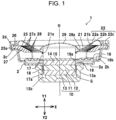
Fig. 1 is a sectional view of a speaker in an embodiment of the present invention; -
Fig. 2 is a partially enlarged view illustrating a half of the sectional view of the speaker inFig. 1 ; -
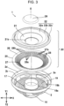
Fig. 3 is an exploded perspective view of the speaker inFig. 1 ; -
Fig. 4 is an exploded sectional view illustrating an example of work to assemble the speaker inFig. 1 ; and -
Fig. 5 is a sectional view illustrating an embodiment of a vehicle-mounted acoustic device in which the speaker inFig. 1 is accommodated in a case. - In the drawings illustrating a
speaker 1 according to embodiments of the present invention, the Y1 direction is the forward direction and the Y2 direction is the backward direction. The Y1-direction side is a first side and the Y2-direction side is a second side. The X direction is the radial direction or diametrical direction. With thespeaker 1, either the Y1 direction or the Y2 direction is a sound generation direction. When thespeaker 1 is accommodated in a case and is used as a vehicle-mounted acoustic device as illustrated inFig. 5 , the Y1 direction is the sound generation direction. The main portion of thespeaker 1 in the embodiment has a true circular shape centered around a center line O in plan view when the main portion is viewed from the front side, as illustrated in the exploded perspective view inFig. 3 . However, the shape in plan view may be elliptical or oblong. - The
speaker 1 has aframe 2. Theframe 2 is formed from a non-magnetic material or a magnetic material. Theframe 2 is cylindrical and its shape in plan view is true circular, as illustrated inFig. 3 . In thespeaker 1, adiaphragm 21 and anedge member 22 are supported on the first side (Y1-directoin side) of theframe 2 and amagnetic circuit 10 forming a magnetic driving portion is fixed on the second side, as illustrated inFigs. 1 and2 . - The
magnetic circuit 10 has amagnet 11 in a discoidal shape, afront yoke 12 attached to the front of themagnet 11, and arear yoke 13 attached to the rear of themagnet 11. Thefront yoke 12 andrear yoke 13 are formed from an iron-based magnetic metal material. Therear yoke 13 has anexternal yoke portion 13a extending forward from the outer circumferential portion, theexternal yoke portion 13a being integrally formed as part of therear yoke 13. A magnetic gap G in a cylindrical shape is formed between the outer circumferential surface of thefront yoke 12 and the inner circumferential surface of theexternal yoke portion 13a. With themagnetic circuit 10,extension members front yoke 12 so as to be overlaid on each other. - A
bottom plate 2a perpendicular to the center line O is formed on the rear side of theframe 2, as illustrated inFigs. 1 and2 . Themagnetic circuit 10 is fixed to the rear surface of thebottom plate 2a by usingcircuit fixing portions 16. Thecircuit fixing portion 16 is a fixing protrusion that protrudes forward from the front surface of theexternal yoke portion 13a of therear yoke 13. To fix themagnetic circuit 10, this fixing protrusion is press-fitted into a fixing hole formed in thebottom plate 2a or is crimped. Thecircuit fixing portion 16 may be a fixing screw with which theexternal yoke portion 13a is fixed to thebottom plate 2a. - A
bobbin 17 is supported in theframe 2 so as to be movable in the front-back direction (Y1-Y2 direction). Thebobbin 17 is cylindrical in shape. Avoice coil 18 is wound around the outer circumferential portion at the end of thebobbin 17 in the backward direction (Y2 direction). Thevoice coil 18 is positioned in the magnetic gap G in themagnetic circuit 10. A magnetic flux, which is generated from themagnet 11 in themagnetic circuit 10 and traverses the magnetic gap G, and a voice coil current flowing in thevoice coil 18 generate a driving force with which thebobbin 17 is caused to vibrate in the front-back direction. Themagnetic circuit 10 andvoice coil 18 form a magnetic driving portion. - A
damper 19 is provided around the outer circumferential portion of thebobbin 17 as illustrated inFigs. 1 and2 . Thedamper 19 is formed from a sheet material having an elastic restoring force such as, for example, a paper material or a resin-impregnated paper material. Thedamper 19 is discoidal in shape as illustrated inFig. 3 . The cross section of thedamper 19 has a corrugated shape as illustrated inFigs. 1 and2 . The innercircumferential portion 19a of thedamper 19 is bonded to the outer circumferential surface of thebobbin 17. The outercircumferential portion 19b of thedamper 19 is bonded to adamper fixing portion 2b formed as part of theframe 2. Thebobbin 17 is supported by thedamper 19 so thatbobbin 17 can vibrate in the front-back direction. When an external force is not exerted on thebobbin 17, the elastic restoring force of thedamper 19 can be used to support thebobbin 17 at a neutral position in the font-back direction. - The
diaphragm 21 is formed from, for example, a paper material or a resin-impregnated paper material so as to have a cone shape. The shape of the cross section of thediaphragm 21 is inclined downward (toward the second side) toward the center line O, as illustrated inFigs. 1 and2 . Acenter hole 21a in thediaphragm 21 has a true circular shape, the diameter of which is slightly larger than the outer diameter of thebobbin 17. Theedge member 22 is formed from, for example, a rubber material, a urethane material, or a rubber-impregnated cloth material. Theedge member 22 has a taperedportion 22a close to the center, adeformed portion 22b close to the outer circumferential, and an outercircumference fixing portion 22c closer to the outer circumferential than thedeformed portion 22b is. The taperedportion 22a is inclined at an angle almost equal to the angle at which thediaphragm 21 is inclined, as illustrated in the sectional views inFigs. 1 and2 . The taperedportion 22a is fixed to the front surface of the outercircumferential portion 21b of thediaphragm 21 by being bonded. Thedeformed portion 22b is curved so as to protrude forward. Thedeformed portion 22b has a lower flexural rigidity than thediaphragm 21. Due to deformation of thedeformed portion 22b, therefore, thediaphragm 21 can be caused to vibrate in the front-back direction. Thedeformed portion 22b has a slight elastic restoring force. When an external force is not exerted on thediaphragm 21, thedeformed portion 22b functions together with thedamper 19 so as to support thediaphragm 21 at the neutral position in the font-back direction. The outercircumference fixing portion 22c of theedge member 22 has a ring shape centered around the center line O. The outercircumference fixing portion 22c has a certain thickness in the radial direction (X direction). - An
edge accepting portion 2c is formed at the front of theframe 2, as illustrated inFigs. 1 and2 . Theedge accepting portion 2c is a ring-shaped region. The front surface (accepting surface) oriented forward (in the Y1 direction) is a flat surface perpendicular to the center line O.An opposing wall 2d is provided as part of theframe 2, the opposingwall 2d extending further forward from the outer circumference of theedge accepting portion 2c. The opposingwall 2d has a cylindrical shape centered around the center line O. A plurality ofopenings 2e are formed in an outer circumferential surface of theframe 2, the outer circumferential surface being more on the rear side (Y2-directoin side) than theedge accepting portion 2c, as illustrated inFig. 3 . A space defined by thediaphragm 21,edge member 22, anddamper 19 communicates with a space outside theframe 2 through theopenings 2e. - An
edge support member 25 is fixed to theedge accepting portion 2c of theframe 2 by being bonded, and the outercircumference fixing portion 22c of theedge member 22 is fixed to the front of theedge support member 25 by being bonded, as illustrated inFigs. 1 and2 . Theedge support member 25 has an edge member support function for preventing theedge member 22 from being deformed during assembling work, a function used as a gasket that assures airtightness at a bonded portion between theedge accepting portion 2c and theedge member 22, and a vibration restriction function for restricting backward movement of theedge member 22 anddiaphragm 21 when they are incorporated into theframe 2. - The
edge support member 25 has an interveningportion 26 in a ring shape at the outermost circumference and also has a restrictingportion 27 extending inward beyond the interveningportion 26 in theframe 2, as illustrated inFig. 3 . The front surface, oriented forward (in the Y1 direction), of the restrictingportion 27 is the restrictingsurface 27a, as illustrated inFig. 2 . The restrictingsurface 27a is a tapered surface inclined downward (in the Y2 direction) toward the center line O. The restrictingportion 27 has a comb shape havingmany vents 28, as illustrated inFig. 3 . Eachvent 28 is a groove. Anopen end 28a of thevent 28 is open toward the center line O. An outer circumference inner-end 28b of thevent 28 is positioned at a boundary between the interveningportion 26 and the restrictingportion 27. Grooves, each of which is thevent 28, are circumferentially arranged at a constant pitch. A tooth of the comb is formed between each twoadjacent vents 28. In the restrictingportion 27 of theedge support member 25, eachvent 28 extends from the first side (Y1-direction side) to the second side (Y2-direction side). Since the restrictingportion 27 is comb-shaped, the total opening area ratio of thevents 28 can be increased. Thevent 28 is not limited to a groove of a comb shape.Vents 28 may be formed by forming many circular or rectangular through-holes in the restrictingportion 27. - In work to assemble the
speaker 1, themagnetic circuit 10 is fixed to thebottom plate 2a of theframe 2 by using thecircuit fixing portions 16. Thebobbin 17, around which thevoice coil 18 is wound, is inserted into theframe 2 from the front side in a state in which thebobbin 17 is fitted into a cylindrical tool so that thevoice coil 18 is positioned in the magnetic gap G. In a state in which thevoice coil 18 is positioned in the magnetic gap G, thedamper 19 is assembled to the outer circumference of thebobbin 17 positioned by the cylindrical tool. The innercircumferential portion 19a of thedamper 19 is bonded to the outer circumferential surface of thebobbin 17. Then, the outercircumferential portion 19b of thedamper 19 is bonded to thedamper fixing portion 2b of theframe 2. - Three members,
diaphragm 21,edge member 22 andedge support member 25, are bonded together in advance to form apartial assembly 20, as illustrated inFigs. 3 and4 . Thediaphragm 21 andedge member 22 are mutually positioned by using a tool and are then bonded. Theedge member 22 andedge support member 25 are also mutually positioned by using a tool, after which the outercircumference fixing portion 22c of theedge member 22 is fixed to the front surface of the interveningportion 26 of theedge support member 25 with an adhesive. When thispartial assembly 20 is incorporated into theframe 2 as described later, thediaphragm 21,edge member 22, andedge support member 25 can be highly precisely positioned in theframe 2 to assemble them. When the outercircumference fixing portion 22c of theedge member 22 is handled at a time of storage or during assembling work, the outercircumference fixing portion 22c is protected by being reinforced by theedge support member 25. Therefore, it becomes easy to prevent theedge member 22 from being deformed before thediaphragm 21 andedge member 22 are assembled to theframe 2. - When the
partial assembly 20 is incorporated into theframe 2 from the front side as illustrated inFig. 4 in a state in which thebobbin 17 is positioned by the cylindrical tool so that thecenter hole 21a in thediaphragm 21 is fitted to the outer circumference of thebobbin 17, thecenter hole 21a in thediaphragm 21 is positioned on the outer circumferential surface of thebobbin 17. Therefore, the whole of thepartial assembly 20 is highly precisely positioned in theframe 2. The opposingwall 2d at the foremost portion of theframe 2 is formed so that the dimension of the inner diameter of the opposingwall 2d is slightly larger than the dimension of the outer diameter of the outercircumferential end face 25a of theedge support member 25. Therefore, when thepartial assembly 20 is incorporated into theframe 2, thepartial assembly 20 can be smoothly inserted with the outercircumferential end face 25a of theedge support member 25 facing the inner surface of the opposingwall 2d. With thepartial assembly 20 positioned as described above, the inner circumferential end face of thecenter hole 21a in thediaphragm 21 is fixed to the outer circumferential surface of thebobbin 17 with an adhesive. Then, the interveningportion 26 of theedge support member 25 is bonded to theedge accepting portion 2c of theframe 2. - After the
partial assembly 20 has been assembled to the inside of theframe 2, the cylindrical tool is removed and acap member 29 is attached. Specifically, thebottom end 29a of thecap member 29 is fixed to the front surface of thediaphragm 21 with an adhesive. Thecap member 29 is formed from a sheet material that can seal air. Upon completion of the assembling of thespeaker 1 illustrated inFigs. 1 and2 , the inner space in thebobbin 17 is covered by thecap member 29 from the front side. The interior of theframe 2 is divided into a space on the front side (Y1-direction side) and a space on the rear side (Y2-directoin side) along thediaphragm 21,edge member 22, andcap member 29, which form a boundary. - After the
speaker 1 has been assembled, theedge support member 25 extends toward the interior of theframe 2 beyond the end (a) of theedge accepting portion 2c of theframe 2 on the inner side, as illustrated inFig. 2 . This extending portion is the restrictingportion 27. A restrictingsurface 27a, which is the front surface of the restrictingportion 27, faces theedge member 22 anddiaphragm 21 from the rear side (second side). An inclination angle α on a cross sections of thediaphragm 21 and the taperedportion 22a of theedge member 22 and an inclination angle β of the restrictingsurface 27a of theedge support member 25 are equal to or almost equal to each other. Here, the phrase "almost equal" means that the difference between the inclination angle α and the inclination angle β is ±5 degrees or less and preferably ±3 degrees or less. - In
Fig. 2 , the minimum value of the facing distance between the restrictingsurface 27a and thediaphragm 21 andedge member 22 in the front-back direction (Y1-Y2 direction) is indicated by H1; the minimum value of the facing distance between thebackmost end 17a of thebobbin 17 and theinner bottom 13b of therear yoke 13, which is part of themagnetic circuit 10, in the front-back direction is indicated by H2; and the minimum value of the facing distance between thedamper 19 and thecircuit fixing portion 16, which functions as a damper restricting portion, in the front-back direction is indicated by H3. The minimum value H2 is preferably the greatest, followed by the minimum value H1, followed by the minimum value H3. Alternatively, the minimum value H1 is preferably the greatest, followed by the minimum value H2, followed by the minimum value H3. - Next, an example of the operation of the
speaker 1 will be described. -
Fig. 5 illustrates anacoustic device 30, intended to be mounted on a vehicle, in which thespeaker 1 in the embodiment of the present invention is used. Theacoustic device 30 is attached to the body of an automobile and generates a travel alarm sound toward the outside of the body. Theacoustic device 30 is used in a severe environment in which theacoustic device 30 tends to undergo moisture such as rain water. - With the
acoustic device 30, afront case 31 and arear case 32 are bonded with a packing 33 intervening between them. Thespeaker 1 is fixed in thefront case 31 by a fixing support member (not illustrated). Aspeaker abutting portion 34 in a ring shape is formed at the front of the interior of thefront case 31. The opposingwall 2d at the front of theframe 2 is attached to the outer circumference of thespeaker abutting portion 34. Thespeaker abutting portion 34 and opposingwall 2d are bonded together so that a clearance is not formed between them. As a result, the interior of thefront case 31 andrear case 32 is divided into afront space 41 and arear space 42 by thediaphragm 21,edge member 22, andcap member 29. -
Sound generation ports 35 are formed in thefront wall 31a of thefront case 31 so as to pass through thefront wall 31a. Thefront space 41 is an external ventilation space communicating with the external space through thesound generation ports 35. Avent hole 36 is formed in therear end wall 32a of therear case 32 so as to pass through therear end wall 32a. Thevent hole 36 is covered with aclosing film 37 from the inside. Theclosing film 37 is formed from a material that allows air to pass through theclosing film 37 but does not transmit a liquid. As a result, therear space 42 is a closed space, in which moisture coming from the outside does not come into direct contact with the magnetic driving portion, which includes themagnetic circuit 10, in thespeaker 1. - When a current passes through the
voice coil 18 in thespeaker 1, a magnetic flux traversing the magnetic gap G in themagnetic circuit 10 and a voice coil current flowing in thevoice coil 18 generate a driving force exerted on thebobbin 17 in the front-back direction, by which thebobbin 17,diaphragm 21, andedge member 22 are caused to vibrate in the front-back direction. Sound pressure is given to thefront space 41 due to this vibration is then transmitted to the outside space through thesound generation ports 35, generating a travel alarm sound toward the outside. Sound pressure having a phase opposite to the phase of sound pressure given to thefront space 41 is given to therear space 42 due to the vibration of thediaphragm 21 andedge member 22. Since the interior of therear space 42 communicates with the outside of therear case 32 through thevent hole 36, even when the density of air in therear space 42 changes, it is possible to suppress an excessive damper effect, which would otherwise be caused by compressed air in therear space 42. - In normal sound generation operation, a movable portion including the
diaphragm 21,bobbin 17, and the like does not abut the internal surface of theframe 2. However, if a non-standard excessive current flows in thevoice coil 18 due to, for example, a malfunction of an acoustic circuit, the movable portion may be forcibly moved backward (in the Y2 direction) over a long distance. As described above with reference toFig. 2 , the relation of the minimum values of the facing distances between the movable portion and the inner surfaces of theframe 2 is as follows: H2 is the greatest, followed by H1, followed by H3. Therefore, at a time when the movable portion moves backward by the minimum value H3, thedamper 19 abuts thecircuit fixing portions 16, which function as a damper restricting portion, so thediaphragm 21 andedge member 22 do not abut the restrictingsurface 27a of theedge support member 25 in such a way that an impact occurs and thebackmost end 17a of thebobbin 17 also does not abut theinner bottom 13b of therear yoke 13 in such a way that an impact occurs. As a result, it is possible to prevent thediaphragm 21,edge member 22, andbobbin 17 from being deformed or damaged. - In an environmental test for the
acoustic device 30, which has been assembled, before it is shipped or in a state in which theacoustic device 30 is actually used with theacoustic device 30 attached to the body of an automobile, temperature in the environment in which theacoustic device 30 is placed may greatly rise, after which the temperature of the case may rapidly drop because, for example, water is poured. When this happens, an air flow in thevent hole 36 cannot follow a change in pressure and pressure in therear space 42 thereby rapidly drops. When pressure in therear space 42 drops, the movable portion moves backward and thedamper 19 abuts thecircuit fixing portions 16, after which thediaphragm 21 andedge member 22 tend to be deformed by being further attracted backward. However, since theedge member 22 anddiaphragm 21 abut the restrictingsurface 27a of theedge support member 25, it is possible to prevent thediaphragm 21 andedge member 22 from being excessively deformed. - As illustrated in
Fig. 2 , thediaphragm 21, the taperedportion 22a of theedge member 22, and the restrictingsurface 27a of theedge support member 25 are inclined in the same orientation; the inclination angle α and inclination angle β are almost equal to each other; and thediaphragm 21 and the taperedportion 22a and the restrictingsurface 27a face each other substantially in parallel. Therefore, when thediaphragm 21 andedge member 22 start to deform backward, they abut the restrictingsurface 27a, so the cone shape of thediaphragm 21 and the taper shape of the taperedportion 22a can be maintained. As a result, it is possible to prevent thedeformed portion 22b of theedge member 22 from being excessively deformed; otherwise, the direction in which thedeformed portion 22b protrudes would be inverted. When pressure in therear space 42 is recovered, the shapes of thediaphragm 21 andedge member 22 can be restored. - With the
speaker 1 in the embodiment, the restrictingsurface 27a faces the back of thediaphragm 21 andedge member 22 so as to be spaced by a distance of the minimum value H1. Therefore, when thediaphragm 21 andedge member 22 vibrate in the font-back direction in normal sound generation operation, the vibration property of thediaphragm 21 may be affected by a change in the pressure of air between thediaphragm 21 andedge member 22 and the restrictingsurface 27a. However, since many comb-shaped grooves are formed in the restrictingportion 27 of theedge support member 25 as thevents 28 as illustrated inFig. 3 , a large amount of air can be moved between a space defined by thediaphragm 21,edge member 22, and restrictingsurface 27a and a space behind the restrictingportion 27. Therefore, when thediaphragm 21 andedge member 22 vibrate in the front-back direction, it is possible to restrain the space defined by thediaphragm 21,edge member 22, and restrictingsurface 27a from providing an excessive damper effect, preventing the vibration property of thediaphragm 21 from being adversely affected. - The
edge support member 25 has an edge member support function that prevents theedge member 22 from being deformed during assembling work, a function used as a gasket that assures airtightness at a bonded portion between theedge accepting portion 2c and theedge member 22, and a vibration restriction function that restricts backward movement of theedge member 22 anddiaphragm 21. In many conventional speakers as well, a gasket is interposed between the frame and the edge member. With thespeaker 1 in the embodiment, however, the gasket also functions as the restrictingportion 27. This prevents the number of parts from increasing. Thediaphragm 21,edge member 22, andedge support member 25 are bonded together to form thepartial assembly 20 as illustrated inFigs. 3 and4 . Thepartial assembly 20 is incorporated into theframe 2. This simplifies work to incorporate the restrictingportion 27 and enables the relative positions of the restrictingportion 27,diaphragm 21, andedge member 22 to be highly precisely determined.
Claims (5)
- A speaker comprising a frame (2), a diaphragm (21), an edge member (22) disposed between the frame (2) and an outer circumferential portion of the diaphragm (21), and a magnetic driving portion that causes the diaphragm (21) to vibrate, the diaphragm (21) being positioned on a first side, the magnetic driving portion being positioned on a second side, the speaker further comprising:an edge support member (25) interposed and fixed between an edge accepting portion (2c) formed as part of the frame (2) and an outer circumference fixing portion (22c) of the edge member (22), and a restricting portion (27) extending inward beyond the edge accepting portion (2c) is formed as part of the edge support member (25); andthe restricting portion (27) is positioned more on the second side than the edge member (22) and faces the edge member (22) with a gap between the restricting portion (27) and the edge member (22).
- The speaker according to Claim 1, wherein a vent (28) extending from the first side to the second side is formed in the restricting portion (27).
- The speaker according to Claim 2, wherein a groove open toward a center of the frame (2) is formed in the restricting portion (27) as the vent (28), and a plurality of grooves are circumferentially formed at intervals.
- The speaker according to one of Claims 1 - 3,
wherein an opposing wall (2d) facing an outer circumferential end face of the edge support member (25) is provided as part of the frame (2). - An acoustic device comprising the speaker according to any one of Claims 1 to 4, wherein:the frame (2) is fixed in a case; andan interior of the case is divided into an external ventilation space (41) more on the first side than the diaphragm (21) and a closed space (42) more on the second side than the diaphragm (21).
Applications Claiming Priority (1)
| Application Number | Priority Date | Filing Date | Title |
|---|---|---|---|
| JP2022139919A JP2024035456A (en) | 2022-09-02 | 2022-09-02 | A speaker and an audio device using the speaker |
Publications (1)
| Publication Number | Publication Date |
|---|---|
| EP4333462A1 true EP4333462A1 (en) | 2024-03-06 |
Family
ID=87845916
Family Applications (1)
| Application Number | Title | Priority Date | Filing Date |
|---|---|---|---|
| EP23193511.5A Pending EP4333462A1 (en) | 2022-09-02 | 2023-08-25 | Speaker and acoustic device using speaker |
Country Status (4)
| Country | Link |
|---|---|
| US (1) | US12532119B2 (en) |
| EP (1) | EP4333462A1 (en) |
| JP (1) | JP2024035456A (en) |
| CN (1) | CN117651241A (en) |
Citations (5)
| Publication number | Priority date | Publication date | Assignee | Title |
|---|---|---|---|---|
| WO2006035413A1 (en) * | 2004-09-30 | 2006-04-06 | Pss Belgium N.V. | Loudspeaker with an acoustic membrane |
| CN107809711A (en) * | 2017-12-22 | 2018-03-16 | 奥音精密机械(镇江)有限公司 | A kind of free bonding Fast Installation loudspeaker |
| CN110620974A (en) * | 2018-06-19 | 2019-12-27 | 宁波升亚电子有限公司 | High pitch loudspeaker and manufacturing method thereof |
| JP2021034864A (en) | 2019-08-23 | 2021-03-01 | アルパイン株式会社 | Audio equipment |
| WO2021056898A1 (en) * | 2019-09-29 | 2021-04-01 | 歌尔股份有限公司 | Centring disk and sound production device |
Family Cites Families (5)
| Publication number | Priority date | Publication date | Assignee | Title |
|---|---|---|---|---|
| JPH0170491U (en) * | 1987-10-28 | 1989-05-10 | ||
| JP2872291B2 (en) * | 1989-08-24 | 1999-03-17 | 松下電器産業株式会社 | Transmitter / receiver unit for telephone handset |
| US20020114484A1 (en) * | 2001-01-04 | 2002-08-22 | Crisco John D. | Compact narrow band loudspeaker enclosure |
| DE102013011937B3 (en) * | 2013-07-17 | 2014-10-09 | Eberspächer Exhaust Technology GmbH & Co. KG | Sound generator for an anti-noise system for influencing exhaust noise and / or Ansauggeräuschen a motor vehicle |
| US20200374613A1 (en) * | 2017-08-08 | 2020-11-26 | Panasonic Intellectual Property Management Co., Ltd. | Loudspeaker and earphones |
-
2022
- 2022-09-02 JP JP2022139919A patent/JP2024035456A/en active Pending
-
2023
- 2023-08-25 US US18/455,839 patent/US12532119B2/en active Active
- 2023-08-25 EP EP23193511.5A patent/EP4333462A1/en active Pending
- 2023-08-29 CN CN202311092540.2A patent/CN117651241A/en active Pending
Patent Citations (5)
| Publication number | Priority date | Publication date | Assignee | Title |
|---|---|---|---|---|
| WO2006035413A1 (en) * | 2004-09-30 | 2006-04-06 | Pss Belgium N.V. | Loudspeaker with an acoustic membrane |
| CN107809711A (en) * | 2017-12-22 | 2018-03-16 | 奥音精密机械(镇江)有限公司 | A kind of free bonding Fast Installation loudspeaker |
| CN110620974A (en) * | 2018-06-19 | 2019-12-27 | 宁波升亚电子有限公司 | High pitch loudspeaker and manufacturing method thereof |
| JP2021034864A (en) | 2019-08-23 | 2021-03-01 | アルパイン株式会社 | Audio equipment |
| WO2021056898A1 (en) * | 2019-09-29 | 2021-04-01 | 歌尔股份有限公司 | Centring disk and sound production device |
Also Published As
| Publication number | Publication date |
|---|---|
| CN117651241A (en) | 2024-03-05 |
| US12532119B2 (en) | 2026-01-20 |
| JP2024035456A (en) | 2024-03-14 |
| US20240080622A1 (en) | 2024-03-07 |
Similar Documents
| Publication | Publication Date | Title |
|---|---|---|
| EP2603017B1 (en) | Speaker | |
| JP7004436B2 (en) | In-vehicle speaker | |
| US20170180868A1 (en) | Loudspeaker | |
| JP6775893B2 (en) | In-vehicle audio equipment | |
| US12532119B2 (en) | Speaker and acoustic device using speaker | |
| EP1786238B1 (en) | Speaker apparatus | |
| JP7635555B2 (en) | Speaker device and vehicle door | |
| US5376853A (en) | Electroacoustic transducer | |
| JP4301531B2 (en) | Multi-functional pronunciation body | |
| US7331420B2 (en) | Frame for speaker device and speaker device | |
| JP4723999B2 (en) | Speaker and speaker unit | |
| JP7337450B2 (en) | sound equipment | |
| EP0940602B1 (en) | Vibration insulating mount | |
| JP7790612B2 (en) | Speaker device and vehicle door | |
| JP7528658B2 (en) | Speaker system | |
| JP2006258153A (en) | Liquid-filled vibration isolator | |
| JP7416257B2 (en) | Vehicle doors and sound equipment | |
| JP4425086B2 (en) | speaker | |
| JP4113192B2 (en) | Liquid-filled vibration isolator | |
| CN115720304A (en) | Loudspeakers and doors for vehicles | |
| JP2024081993A (en) | Speakers and vehicle doors | |
| JP4113193B2 (en) | Liquid-filled vibration isolator | |
| JP3438510B2 (en) | Anti-vibration support device | |
| JP2024155363A (en) | Speakers and vehicle doors | |
| CN120752931A (en) | Speaker support structure |
Legal Events
| Date | Code | Title | Description |
|---|---|---|---|
| PUAI | Public reference made under article 153(3) epc to a published international application that has entered the european phase |
Free format text: ORIGINAL CODE: 0009012 |
|
| STAA | Information on the status of an ep patent application or granted ep patent |
Free format text: STATUS: THE APPLICATION HAS BEEN PUBLISHED |
|
| AK | Designated contracting states |
Kind code of ref document: A1 Designated state(s): AL AT BE BG CH CY CZ DE DK EE ES FI FR GB GR HR HU IE IS IT LI LT LU LV MC ME MK MT NL NO PL PT RO RS SE SI SK SM TR |
|
| STAA | Information on the status of an ep patent application or granted ep patent |
Free format text: STATUS: REQUEST FOR EXAMINATION WAS MADE |
|
| 17P | Request for examination filed |
Effective date: 20240828 |
|
| RBV | Designated contracting states (corrected) |
Designated state(s): AL AT BE BG CH CY CZ DE DK EE ES FI FR GB GR HR HU IE IS IT LI LT LU LV MC ME MK MT NL NO PL PT RO RS SE SI SK SM TR |
|
| STAA | Information on the status of an ep patent application or granted ep patent |
Free format text: STATUS: EXAMINATION IS IN PROGRESS |
|
| 17Q | First examination report despatched |
Effective date: 20260115 |