EP4333458A1 - Acoustic device - Google Patents
Acoustic device Download PDFInfo
- Publication number
- EP4333458A1 EP4333458A1 EP23192738.5A EP23192738A EP4333458A1 EP 4333458 A1 EP4333458 A1 EP 4333458A1 EP 23192738 A EP23192738 A EP 23192738A EP 4333458 A1 EP4333458 A1 EP 4333458A1
- Authority
- EP
- European Patent Office
- Prior art keywords
- sound generation
- speaker unit
- listener
- horizontal direction
- case
- Prior art date
- Legal status (The legal status is an assumption and is not a legal conclusion. Google has not performed a legal analysis and makes no representation as to the accuracy of the status listed.)
- Pending
Links
Images





Classifications
-
- H—ELECTRICITY
- H04—ELECTRIC COMMUNICATION TECHNIQUE
- H04R—LOUDSPEAKERS, MICROPHONES, GRAMOPHONE PICK-UPS OR LIKE ACOUSTIC ELECTROMECHANICAL TRANSDUCERS; ELECTRIC HEARING AIDS; PUBLIC ADDRESS SYSTEMS
- H04R1/00—Details of transducers, loudspeakers or microphones
- H04R1/20—Arrangements for obtaining desired frequency or directional characteristics
- H04R1/32—Arrangements for obtaining desired frequency or directional characteristics for obtaining desired directional characteristic only
- H04R1/40—Arrangements for obtaining desired frequency or directional characteristics for obtaining desired directional characteristic only by combining a number of identical transducers
- H04R1/403—Arrangements for obtaining desired frequency or directional characteristics for obtaining desired directional characteristic only by combining a number of identical transducers loud-speakers
-
- H—ELECTRICITY
- H04—ELECTRIC COMMUNICATION TECHNIQUE
- H04R—LOUDSPEAKERS, MICROPHONES, GRAMOPHONE PICK-UPS OR LIKE ACOUSTIC ELECTROMECHANICAL TRANSDUCERS; ELECTRIC HEARING AIDS; PUBLIC ADDRESS SYSTEMS
- H04R5/00—Stereophonic arrangements
- H04R5/02—Spatial or constructional arrangements of loudspeakers
- H04R5/023—Spatial or constructional arrangements of loudspeakers in a chair, pillow
-
- H—ELECTRICITY
- H04—ELECTRIC COMMUNICATION TECHNIQUE
- H04R—LOUDSPEAKERS, MICROPHONES, GRAMOPHONE PICK-UPS OR LIKE ACOUSTIC ELECTROMECHANICAL TRANSDUCERS; ELECTRIC HEARING AIDS; PUBLIC ADDRESS SYSTEMS
- H04R1/00—Details of transducers, loudspeakers or microphones
- H04R1/20—Arrangements for obtaining desired frequency or directional characteristics
-
- B—PERFORMING OPERATIONS; TRANSPORTING
- B60—VEHICLES IN GENERAL
- B60N—SEATS SPECIALLY ADAPTED FOR VEHICLES; VEHICLE PASSENGER ACCOMMODATION NOT OTHERWISE PROVIDED FOR
- B60N2/00—Seats specially adapted for vehicles; Arrangement or mounting of seats in vehicles
- B60N2/80—Head-rests
- B60N2/879—Head-rests with additional features not related to head-rest positioning, e.g. heating or cooling devices or loudspeakers
-
- H—ELECTRICITY
- H04—ELECTRIC COMMUNICATION TECHNIQUE
- H04R—LOUDSPEAKERS, MICROPHONES, GRAMOPHONE PICK-UPS OR LIKE ACOUSTIC ELECTROMECHANICAL TRANSDUCERS; ELECTRIC HEARING AIDS; PUBLIC ADDRESS SYSTEMS
- H04R1/00—Details of transducers, loudspeakers or microphones
- H04R1/02—Casings; Cabinets ; Supports therefor; Mountings therein
- H04R1/025—Arrangements for fixing loudspeaker transducers, e.g. in a box, furniture
-
- H—ELECTRICITY
- H04—ELECTRIC COMMUNICATION TECHNIQUE
- H04R—LOUDSPEAKERS, MICROPHONES, GRAMOPHONE PICK-UPS OR LIKE ACOUSTIC ELECTROMECHANICAL TRANSDUCERS; ELECTRIC HEARING AIDS; PUBLIC ADDRESS SYSTEMS
- H04R1/00—Details of transducers, loudspeakers or microphones
- H04R1/20—Arrangements for obtaining desired frequency or directional characteristics
- H04R1/22—Arrangements for obtaining desired frequency or directional characteristics for obtaining desired frequency characteristic only
- H04R1/28—Transducer mountings or enclosures modified by provision of mechanical or acoustic impedances, e.g. resonator, damping means
- H04R1/2807—Enclosures comprising vibrating or resonating arrangements
- H04R1/2815—Enclosures comprising vibrating or resonating arrangements of the bass reflex type
- H04R1/2819—Enclosures comprising vibrating or resonating arrangements of the bass reflex type for loudspeaker transducers
-
- H—ELECTRICITY
- H04—ELECTRIC COMMUNICATION TECHNIQUE
- H04R—LOUDSPEAKERS, MICROPHONES, GRAMOPHONE PICK-UPS OR LIKE ACOUSTIC ELECTROMECHANICAL TRANSDUCERS; ELECTRIC HEARING AIDS; PUBLIC ADDRESS SYSTEMS
- H04R1/00—Details of transducers, loudspeakers or microphones
- H04R1/20—Arrangements for obtaining desired frequency or directional characteristics
- H04R1/22—Arrangements for obtaining desired frequency or directional characteristics for obtaining desired frequency characteristic only
- H04R1/28—Transducer mountings or enclosures modified by provision of mechanical or acoustic impedances, e.g. resonator, damping means
- H04R1/2807—Enclosures comprising vibrating or resonating arrangements
- H04R1/283—Enclosures comprising vibrating or resonating arrangements using a passive diaphragm
- H04R1/2834—Enclosures comprising vibrating or resonating arrangements using a passive diaphragm for loudspeaker transducers
-
- H—ELECTRICITY
- H04—ELECTRIC COMMUNICATION TECHNIQUE
- H04R—LOUDSPEAKERS, MICROPHONES, GRAMOPHONE PICK-UPS OR LIKE ACOUSTIC ELECTROMECHANICAL TRANSDUCERS; ELECTRIC HEARING AIDS; PUBLIC ADDRESS SYSTEMS
- H04R2499/00—Aspects covered by H04R or H04S not otherwise provided for in their subgroups
- H04R2499/10—General applications
- H04R2499/13—Acoustic transducers and sound field adaptation in vehicles
Definitions
- the present invention relates to an acoustic device that gives sound pressure toward a listener, for example sitting on a seat in an automobile.
- a speaker device incorporated into the backrest or headrest of a chair is described in JP 2007-221485 A .
- this speaker device an enclosure in which space having a predetermined volume is left is incorporated into the backrest or headrest.
- a hole is formed at the front of the enclosure.
- a speaker unit that converts electric signals to sounds is attached in the hole.
- a tubular duct which works as a bass-reflex duct, is linked to the enclosure. As a whole, therefore, the speaker unit functions as a bass-reflex speaker.
- a tubular duct extends upward from a speaker unit and the duct end is oriented to the ear of the listener.
- a speaker in Fig. 5 a speaker unit is positioned slightly below the ear of the listener and the duct end of a tubular duct is positioned on the outside of the speaker unit in the horizontal direction so as to be side by side with the speaker unit.
- the sound pressure levels of audible low-pitched sounds in a bass-reflex speaker vary depending on the length of a path through which sound pressure directed from the duct end arrives at the inlet of the external auditory meatus.
- the opening at the end of the duct is a true circle in shape, and the area of the opening is small.
- the height position of the inlet of the external auditory meatus varies depending on the sitting height of the sitting listener or the position of the inlet of the external auditory meatus on the head of the listener or when the listener changes the sitting posture and the height position of the inlet of the external auditory meatus is thereby changed, the length of the path for low-pitched sounds from the duct end to the inlet of the external auditory meatus greatly changes.
- the present invention addresses the conventional problem described above with the object of providing an acoustic device that can effectively provide sounds expected for a bass-reflex speaker even when the position of the ear of the listener, for example sitting on a seat in an automobile, changes.
- the present invention relates to an acoustic device according to the appended claims. Embodiments are disclosed in the dependent claims.
- An acoustic device has a case and a speaker unit disposed in the case.
- a direction in which the face of a listener is oriented is referred to as a forward direction
- a side opposite to a side in the forward direction is referred to as a rear side
- a direction in which the left and right ears of the listener are aligned is referred to as a horizontal direction
- a direction orthogonal to both the forward direction and the horizontal direction is referred to as an up-down direction.
- the case is positioned on the rear side of the listener.
- the speaker unit is disposed so that sounds generated by it are directed forward.
- the case accommodates an air chamber to which air vibration on the rear side of the speaker unit is transmitted and a bass-reflex port that communicates with the air chamber and is open in the forward direction.
- the opening dimension in the up-down direction is larger than the opening dimension in the horizontal direction.
- the acoustic device of the present invention can be structured so that a pair of speaker units and a pair of bass-reflex ports are provided so that each pair is line-symmetric in the horizontal direction with respect to a center line extending in the up-down direction.
- the case of the acoustic device of the present invention preferably accommodates a head-facing portion that faces the back of the head of the listener, sound generation spaces, to each of which air vibration in front of one of the speaker units is transmitted, and sound generation openings, each of which communicates with one of the sound generation spaces and is open at one of both ends of the head-facing portion in the horizontal direction.
- Each of the bass-reflex ports is preferably open on the outside of one of the sound generation openings in the horizontal direction.
- the opening dimension in the up-down direction is preferably larger than the opening dimension in the horizontal direction.
- An acoustic device has a case and a speaker unit disposed in the case.
- a direction in which the face of a listener is oriented is referred to as a forward direction
- a side opposite to a side in the forward direction is referred to as a rear side
- a direction in which the left and right ears of the listener are aligned is referred to as a horizontal direction
- a direction orthogonal to both the forward direction and the horizontal direction is referred to as an up-down direction.
- the case is positioned on the rear side of the listener.
- the speaker unit is disposed so that sounds generated by it are directed forward.
- the case accommodates an air chamber to which air vibration on the rear side of the speaker unit is transmitted and a passive vibrating body that receives pressure in the air chamber and operates.
- the passive vibrating body is oriented in the forward direction.
- the dimension of the passive vibrating body in the up-down direction is larger than its dimension in the horizontal direction.
- the acoustic device of the present invention can be structured so that a pair of speaker units and a pair of passive vibrating bodies are provided so that each pair is line-symmetric in the horizontal direction with respect to a center line extending in the up-down direction.
- the case of the acoustic device of the present invention preferably accommodates a head-facing portion that faces the back of the head of the listener, sound generation spaces, to each of which air vibration in front of one of the speaker units is transmitted, and sound generation openings, each of which communicates with one of the sound generation spaces and is open at one of both ends of the head-facing portion in the horizontal direction.
- Each of the passive vibrating bodies is preferably positioned in one of the sound generation spaces.
- the opening dimension in the up-down direction is preferably larger than the opening dimension in the horizontal direction.
- the acoustic device is structured so that the bass-reflex port or passive vibrating body is elongated in the up-down direction. Therefore, even when the height, such as the sitting height, or the position of the ear on the head varies depending on the listener or the height position of the ear changes because the listener changes the posture, such as the sitting posture, an extreme change cab be suppressed in the sound pressure levels of low-pitched sounds to be listened to, so the best sounds can be always obtained.
- FIGs. 1 to 5 An acoustic device 1 according to a first embodiment of the present invention is illustrated in Figs. 1 to 5 .
- the acoustic device 1 is preferably vehicle-mounted.
- the acoustic device 1 has a case 2, which is a head restraint positioned at the top of the sheet back of a seat in an automobile or which forms part of a head restraint by, for example, being embedded in the head restraint.
- the head H of a listener who is an occupant in the automobile is illustrated.
- the acoustic device in the present invention may be attached to a seat provided in a vehicle, such as a train, other than automobiles. Alternatively, the acoustic device may be attached to a seat provided in a house or a theater.
- the Z1-Z2 direction is the front-back direction, the Z1 direction being forward, the Z2 direction being backward.
- the direction in which the face F of the listener is oriented is forward (Z1 direction).
- a portion positioned backward (in the Z2 direction) is the back.
- the X1-X2 direction is the horizontal direction, the X1 direction being leftward, the X2 direction being rightward.
- the direction in which the left ear E and right ear E of the listener are aligned is the horizontal direction.
- the Y1-Y2 direction is the up-down direction, the Y1 direction being upward, the Y2 direction being downward.
- the Y1-Y2 direction is orthogonal to both the front-back direction (Z1-Z2 direction) and the horizontal direction (X1-X2 direction).
- a left-right partition 3 formed so as to be parallel to a Y-Z plane is provided at a position at which the left-right partition 3 divides the structure into two parts in the front-back direction (X1-X2 direction), as illustrated in Fig. 2 .
- a center line O which passes through part of the left-right partition 3 and extends in the up-down direction, is indicated.
- the left half of the vehicle-mounted acoustic device 1 with respect to the left-right partition 3 is a left acoustic portion 10L
- the right half is a right acoustic portion 10R.
- the left acoustic portion 10L and right acoustic portion 10R are line-symmetric with respect to the center line O in the left-right direction and are plane-symmetric with respect to the left-right partition 3 in the left-right direction.
- a head-facing portion 4 is formed so as to face the back of the head H of the listener, as illustrated in Figs. 1 to 3 .
- a cushion 5 is provided in front of the head-facing portion 4 as illustrated in Fig. 2 so that the listener can press the head H against the cushion 5.
- the case 2 is assembled from a plurality of parts formed from synthetic resin materials by being injection-molded or from a plurality of parts formed from light metal materials by being die-cast.
- the left acoustic portion 10L includes a front-back partition 11L at a position on the left side of the left-right partition 3 as illustrated in Figs. 3 and 4 .
- Part of the front-back partition 11L, the part being close to the left-right partition 3, is a speaker support 12L.
- a speaker unit 20L on the left side is fixed to the speaker support 12L.
- a frame 21 is fixed to the speaker support 12L as illustrated in Fig. 4 .
- a magnetic circuit 22 is fixed at the back of the frame 21.
- a diaphragm 23 in a cone shape is supported by an edge member 24 and a damper member 25 so that the diaphragm 23 can vibrate in the front-back direction.
- a bobbin 26 extending backward is fixed to the diaphragm 23.
- a voice coil 27 wound around the bobbin 26 is positioned in a magnetic gap of the magnetic circuit 22.
- the diaphragm 23 vibrates in the front-back direction due to a voice current supplied to the voice coil 27, generating sound pressure (air vibration) in the forward direction (Z1 direction) of the diaphragm 23 and its backward direction (Z2 direction).
- the right acoustic portion 10R also includes a front-back partition 11R. Part of the front-back partition 11R is a speaker support 12R.
- the frame 21 of a speaker unit 20R on the right side is fixed to the speaker support 12R.
- the speaker unit 20R on the right side is identical to the speaker unit 20L on the left side.
- the magnetic circuit 22, diaphragm 23, and the like are supported by the frame 21.
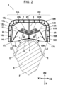
- the interior of the case 2 is partitioned into an air chamber 13L formed behind the front-back partition 11L (in the Z2 direction) and a sound generation space 14L formed ahead of the front-back partition 11L (Z1 direction), as illustrated in Figs. 2 and 4 .
- Air vibration generated forward from the speaker unit 20L is transmitted to the sound generation space 14L, and air vibration generated backward is transmitted to the air chamber 13L.
- the interior of the case 2 is partitioned into an air chamber 13R formed behind the front-back partition 11R and a sound generation space 14R formed ahead of the front-back partition 11R.
- the speaker support 12L in the left acoustic portion 10L is inclined in the clockwise direction in plan view, and a sound generation direction (direction in which air vibration is generated) VL of the speaker unit 20L is slightly inclined toward the left side (X1 direction) with respect to the forward direction (Z1 direction).
- the speaker support 12R in the right acoustic portion 10R is inclined in the counterclockwise direction in plan view, and a sound generation direction VR of the speaker unit 20R is slightly inclined toward the right side (X2 direction) with respect to the forward direction (Z1 direction).
- the sound generation directions VL and VR are oriented at a slightly oblique angle with respect to the forward direction as described above, these directions will be described as the forward direction. That is, in this description, the term "forward direction” and similar terms not only mean a state oriented exactly in the Z1 direction but also mean a direction inclined toward the left side or right side in the left-right direction from the Z1 direction.
- a sound generation opening 15L communicating with the sound generation space 14L is formed so as to be oriented in the forward direction, as illustrated in Figs. 2 to 4 .
- a sound generation opening 15R communicating with the sound generation space 14R is formed so as to be oriented in the forward direction.
- the sound generation opening 15L is open to the outside on the left side of the head-facing portion 4 of the case 2.
- the sound generation opening 15R is open to the outside on the right side of the head-facing portion 4 of the case 2.
- a duct 16L is provided that extends to the inside of the rear wall 2B along the inside of the left wall 2L of the case 2, and a rear opening 18L formed at an end of the duct 16L communicates with the air chamber 13L, as illustrated in Figs. 2 and 4 .
- the duct 16L is open in the forward direction. This opening is a bass-reflex port 17L on the left side.
- a duct 16R is provided that extends to the inside of a rear wall 2B along the inside of the right wall 2R of the case 2.
- a rear opening 18R formed at an end of the duct 16R communicates with the air chamber 13R.
- the duct 16R is open in the forward direction. This opening is a bass-reflex port 17R on the right side.
- the opening dimension W1 in the horizontal direction is larger than the opening dimension H1 in the up-down direction, as illustrated in Fig. 3 .
- the opening dimension H2 in the up-down direction is larger than the opening dimension W2 in the horizontal direction.
- the opening dimension H1 of the sound generation openings 15L and 15R in the up-down direction and the opening dimension H2 of the bass-reflex ports 17L and 17R in the up-down direction are almost equal to each other.
- the phase "almost equal” means that the difference between the opening dimension H1 and the opening dimension H2 is 10% or less of H1 and H2, whichever is larger (in Fig. 3 , H1 is larger) and that the difference is preferably 5% or less.
- the vehicle-mounted acoustic device 1 since the vehicle-mounted acoustic device 1 includes the bass-reflex ports 17L and 17R, it functions as a so-called bass-reflex speaker.
- the duct 16L of the left acoustic portion 10L and the duct 16R of the right acoustic portion 10R have a constant cross section throughout their lengths in their depth direction.
- the resonance frequency of the bass-reflex speaker in a low-frequency band is determined by the cross sections and depths of the ducts 16L and 16R and the volumes of the air chambers 13L and 13R. Air vibration in which low-pitched sounds are enhanced can be generated from the bass-reflex ports 17L and 17R in the forward direction.
- the opening dimension W2 of the bass-reflex ports 17L and 17R in the horizontal direction is determined by the value of the cross section of the ducts 16L and 16R.
- the opening dimension W2 in the horizontal direction can be considerably narrowed.
- the opening dimension W1 of the sound generation openings 15L and 15R formed inside the bass-reflex ports 17L and 17R can be widened accordingly. This enables high-level sound pressure (air vibration) to be effectively given from the speaker units 20L and 20R to the ears E of the listener.
- Air vibration that becomes back pressure having a phase opposite to the phase of air pressure generated in the sound generation direction VL is transmitted from the speaker unit 20L to the air chamber 13L. Then, due to vibration of air in the air chamber 13L and air in the duct 16L, sound pressure in which low-pitched sounds are enhanced as a result of phase inversion is generated forward from the bass-reflex port 17L on the left side and is given to the ear E on the left side. Similarly, in the right acoustic portion 10R, sound pressure in which a low-pitched sound range is enhanced is generated from the bass-reflex port 17R on the right side and is given to the ear E on the right side.
- the acoustic effect, in which low-pitched sounds are enhanced, of the bass-reflex speaker is affected by a balance between a distance L1 (see Fig. 2 ) from the center of the diaphragm 23 in the speaker units 20L and 20R to the sound sensing portion in the ear E and a distance L2 (see Fig. 2 ) from the bass-reflex ports 17L and 17R to the sound sensing portion in the ear E.
- the vehicle-mounted acoustic device 1 is designed so that an optimum acoustic effect in which low-pitched sounds are enhanced is provided by appropriately setting the resonance frequency determined by the cross sections and depths of the ducts 16L and 16R and the volumes of the air chambers 13L and 13R and by taking an appropriate balance between the distances L1 and L2 in the horizontal direction (X1-X2 direction).
- both the opening dimension H1 of the sound generation openings 15L and 15R in the up-down direction and the opening dimension H2 of the bass-reflex ports 17L and 17R in the up-down direction are elongated in the up-down direction, and the opening dimension H1 and opening dimension H2 are almost equal to each other.
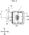
- Fig. 5 illustrates the relative positions of the ear E of the listener on the right side with respect to the position of the vehicle-mounted acoustic device 1 when the ear E of the listener changes in the up-down direction (Y1-Y2 direction).
- the position of the ear E at that time is indicated by (i).
- the shortest distance from the center of the diaphragm 23 in the speaker unit 20R to the sound sensing portion of the ear E on the right side is indicated by B.
- the difference in the level of sound pressure is 1.5 dB or more, the difference is likely to be sensed by the human ear.
- B 10 cm or more
- the difference in the level of sound pressure between when the ear E is at the position (i) and when the ear E is at the position (ii) can be suppressed to 1.5 dB or less.
- H1 and H2, which are almost equal to each other, are 12 cm and B is 14 cm.
- Fig. 8 in which the position of the ear E is indicated by (iii) when the straight line from the center of the diaphragm 23 to the sound sensing portion of the ear E passes through the lower end of the sound generation opening 15R, changes in the level of sound pressure at the positions (i), (ii), and (iii) are indicated.
- Fig. 8 is a logarithmic graph. The horizontal axis indicates the frequency (Hz) of sound pressure (air vibration) generated from the speaker unit, and the vertical axis indicates sound pressure levels (dB) measured at the positions (i), (ii), and (iii). With the vehicle-mounted acoustic device 1 used in measurement, H1 and H2 were 12 cm and B was 14 cm.
- Fig. 9 illustrates an acoustic effect in a comparative example.
- the same vehicle-mounted acoustic device 1 as when the acoustic effect illustrated in Fig. 8 was measured was used and the lower half areas of the sound generation openings 15L and 15R and bass-reflex ports 17L and 17R on the Y2 side were blocked.
- the vehicle-mounted acoustic device 1 in the embodiment of the present invention, however, there was almost no difference in sound pressure level regardless of the position, (i), (ii) or (iii), of the ear E, as illustrated in Fig. 8 .
- the vehicle-mounted acoustic device 1 can effectively provide functions as a bass-reflex speaker and can provide an acoustic effect in which low-pitched sounds are enhanced, regardless of the position, (i), (ii) or (iii), of the ear E. Therefore, even when the sitting height or the position of the ear on the head varies depending on the sitting listener or the height position of the ear changes because the listener changes the sitting posture, superior sounds in which low-pitched sounds are enhanced can be always obtained.
- Figs. 6 and 7 illustrate an acoustic device 101 in a second embodiment of the present invention.
- the acoustic device 101 is preferably vehicle-mounted.
- a case 102 of the acoustic device 101 has a head-facing portion 104.
- the interior of the case 102 is divided into a left acoustic portion 110L and a right acoustic portion 110R as in the interior of the case 2 of the acoustic device 1 illustrated in Fig. 2 .
- Fig. 7 illustrates only part of the left acoustic portion 110L, the left acoustic portion 110L and right acoustic portion 110R are line-symmetric in the horizontal direction with respect to the center line O.
- a front-back partition 111L is provided in the case 102, as illustrated in Fig. 7 .
- Part of the front-back partition 111L is a speaker support 112L.
- the frame 21 of the speaker unit 20L on the left side is fixed to the speaker support 112L.
- the speaker unit 20L in Fig. 7 is identical to the speaker unit 20L in Fig. 4 .
- the front-back partition 111L partitions the interior of the case 102 into an air chamber 113L on the rear side and a sound generation space 114L on the front side.
- a sound generation opening 115L communicating with the sound generation space 114L is formed aside of the head-facing portion 104 so as to be oriented in the forward direction.
- An opening 116L extending in the up-down direction (Y1-Y2 direction) is formed at the front (in the Z1 direction) of the front-back partition 111L.
- a passive vibrating body (diaphragm) 117L is provided in the opening 116L.
- the passive vibrating body 117L is positioned in the sound generation space 114L.
- a damper member 118L is provided between the outer circumference of the passive vibrating body 117L and the inner circumference of the opening 116L.
- the passive vibrating body 117L is formed from a resin sheet, a paper material, or the like.
- the damper member 118L is formed from a thin resin sheet, an elastomer sheet, or the like so as to have certain modulus of elasticity enough to restore the positions of the passive vibrating body 117L in the front-back direction.
- the opening 116L is completely blocked by the passive vibrating body 117L and damper member 118L.
- a passive vibrating body 117R and a damper member 118R are provided in an opening 116R formed in a front-back partition 111R in a sound generation opening 115R, as illustrated in Fig. 6 .
- the opening dimension H3 in the up-down direction (Y1-Y2 direction) is larger than the opening dimension W3 in the horizontal direction (X1-X2 direction), as illustrated in Fig. 6 .
- the dimension H4 in the up-down direction is larger than the dimension W4 in the horizontal direction.
- the values of the opening dimensions W3 and H3 of the sound generation openings 115L and 115R in the vehicle-mounted acoustic device 101 are preferably equal to the values of the opening dimensions W1 and H1 of the sound generation openings 15L and 15R in the vehicle-mounted acoustic device 1 illustrated in Fig. 3 .
- the values of the dimensions W4 and H4 of the passive vibrating bodies 117L and 117R in the vehicle-mounted acoustic device 101 are preferably equal to the values of the opening dimensions W2 and o H2 of the bass-reflex ports 17L and 17R in the vehicle-mounted acoustic device 1 illustrated in Fig. 3 .
- the opening dimension H3 of the sound generation openings 115L and 115R in the up-down direction and the dimension H4 of the passive vibrating bodies 117L and 117R in the up-down direction are almost equal to each other.
- Both the sound generation openings 115L and 115R and passive vibrating bodies 117L and 117R are elongated in the up-down direction. Therefore, even when the position of the ear E of the listener changes in the up-down direction, an acoustic effect in which low-pitched sounds are enhanced and sound pressure is well-balanced can be always obtained.
Landscapes
- Engineering & Computer Science (AREA)
- Physics & Mathematics (AREA)
- Acoustics & Sound (AREA)
- Signal Processing (AREA)
- Health & Medical Sciences (AREA)
- Otolaryngology (AREA)
- Aviation & Aerospace Engineering (AREA)
- Transportation (AREA)
- Mechanical Engineering (AREA)
- Fittings On The Vehicle Exterior For Carrying Loads, And Devices For Holding Or Mounting Articles (AREA)
- Stereophonic Arrangements (AREA)
- Details Of Audible-Bandwidth Transducers (AREA)
- Obtaining Desirable Characteristics In Audible-Bandwidth Transducers (AREA)
Abstract
Description
- The present invention relates to an acoustic device that gives sound pressure toward a listener, for example sitting on a seat in an automobile.
- A speaker device incorporated into the backrest or headrest of a chair is described in
JP 2007-221485 A - With a speaker in
Fig. 3 inJP 2007-221485 A Fig. 5 , a speaker unit is positioned slightly below the ear of the listener and the duct end of a tubular duct is positioned on the outside of the speaker unit in the horizontal direction so as to be side by side with the speaker unit. According to the description in paragraph [0031] and later, in the structure inFig. 5 , there is almost no difference between the length of a path for middle-pitched sounds from the speaker unit to the inlet of the external auditory meatus and the length of a path for low-pitched sounds from the duct end to the inlet of the external auditory meatus, but, in the structure inFig. 3 , the length of a path from the speaker unit to the inlet of the external auditory meatus is shorter than the length of a path from the duct end to the inlet of the external auditory meatus, so the sound pressure levels of low-pitched sounds can be raised. - As described in paragraph [0031] and later in
JP 2007-221485 A JP 2007-221485 A - The present invention addresses the conventional problem described above with the object of providing an acoustic device that can effectively provide sounds expected for a bass-reflex speaker even when the position of the ear of the listener, for example sitting on a seat in an automobile, changes.
- The present invention relates to an acoustic device according to the appended claims. Embodiments are disclosed in the dependent claims.
- An acoustic device according to an aspect of the present invention has a case and a speaker unit disposed in the case.
- A direction in which the face of a listener is oriented is referred to as a forward direction, a side opposite to a side in the forward direction is referred to as a rear side, a direction in which the left and right ears of the listener are aligned is referred to as a horizontal direction, and a direction orthogonal to both the forward direction and the horizontal direction is referred to as an up-down direction.
- The case is positioned on the rear side of the listener. The speaker unit is disposed so that sounds generated by it are directed forward.
- The case accommodates an air chamber to which air vibration on the rear side of the speaker unit is transmitted and a bass-reflex port that communicates with the air chamber and is open in the forward direction.
- With the bass-reflex port, the opening dimension in the up-down direction is larger than the opening dimension in the horizontal direction.
- According to an embodiment, the acoustic device of the present invention can be structured so that a pair of speaker units and a pair of bass-reflex ports are provided so that each pair is line-symmetric in the horizontal direction with respect to a center line extending in the up-down direction.
- The case of the acoustic device of the present invention preferably accommodates a head-facing portion that faces the back of the head of the listener, sound generation spaces, to each of which air vibration in front of one of the speaker units is transmitted, and sound generation openings, each of which communicates with one of the sound generation spaces and is open at one of both ends of the head-facing portion in the horizontal direction.
- Each of the bass-reflex ports is preferably open on the outside of one of the sound generation openings in the horizontal direction.
- With the sound generation opening as well, the opening dimension in the up-down direction is preferably larger than the opening dimension in the horizontal direction.
- An acoustic device according to a further aspect of the present invention has a case and a speaker unit disposed in the case.
- A direction in which the face of a listener is oriented is referred to as a forward direction, a side opposite to a side in the forward direction is referred to as a rear side, a direction in which the left and right ears of the listener are aligned is referred to as a horizontal direction, and a direction orthogonal to both the forward direction and the horizontal direction is referred to as an up-down direction.
- The case is positioned on the rear side of the listener. The speaker unit is disposed so that sounds generated by it are directed forward.
- The case accommodates an air chamber to which air vibration on the rear side of the speaker unit is transmitted and a passive vibrating body that receives pressure in the air chamber and operates.
- The passive vibrating body is oriented in the forward direction. The dimension of the passive vibrating body in the up-down direction is larger than its dimension in the horizontal direction.
- According to an embodiment, the acoustic device of the present invention can be structured so that a pair of speaker units and a pair of passive vibrating bodies are provided so that each pair is line-symmetric in the horizontal direction with respect to a center line extending in the up-down direction.
- The case of the acoustic device of the present invention preferably accommodates a head-facing portion that faces the back of the head of the listener, sound generation spaces, to each of which air vibration in front of one of the speaker units is transmitted, and sound generation openings, each of which communicates with one of the sound generation spaces and is open at one of both ends of the head-facing portion in the horizontal direction.
- Each of the passive vibrating bodies is preferably positioned in one of the sound generation spaces.
- With the sound generation opening as well, the opening dimension in the up-down direction is preferably larger than the opening dimension in the horizontal direction.
- The acoustic device according to aspects of the present invention is structured so that the bass-reflex port or passive vibrating body is elongated in the up-down direction. Therefore, even when the height, such as the sitting height, or the position of the ear on the head varies depending on the listener or the height position of the ear changes because the listener changes the posture, such as the sitting posture, an extreme change cab be suppressed in the sound pressure levels of low-pitched sounds to be listened to, so the best sounds can be always obtained.
-
Fig. 1 is a perspective view in which the head of a listener and a vehicle-mounted acoustic device, which is a first embodiment of the acoustic device of the present invention, are viewed diagonally from the front of the vehicle-mounted acoustic device; -
Fig. 2 is a plan sectional view illustrating the head of the listener and the vehicle-mounted acoustic device in the first embodiment; -
Fig. 3 is a perspective view in which the vehicle-mounted acoustic device inFig. 1 is viewed diagonally from the front of the vehicle-mounted acoustic device; -
Fig. 4 is a perspective view illustrating a partial section of the vehicle-mounted acoustic device inFig. 3 , as taken along a plane including line IV-IV; -
Fig. 5 is a partial longitudinal sectional view of the vehicle-mounted acoustic device inFig. 1 , as taken along a plane including line V-V; -
Fig. 6 is a perspective view in which another vehicle-mounted acoustic device, which is a second embodiment of the acoustic device of the present invention, is viewed diagonally from the front of the other vehicle-mounted acoustic device; -
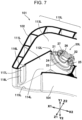
Fig. 7 is a perspective view illustrating a partial section of the vehicle-mounted acoustic device inFig. 6 , as taken along a plane including line VII-VII; -
Fig. 8 is a graph illustrating the acoustic effect of the vehicle-mounted acoustic device in the first embodiment; and -
Fig. 9 is a graph illustrating an acoustic effect in a comparative example. - An
acoustic device 1 according to a first embodiment of the present invention is illustrated inFigs. 1 to 5 . Theacoustic device 1 is preferably vehicle-mounted. Theacoustic device 1 has acase 2, which is a head restraint positioned at the top of the sheet back of a seat in an automobile or which forms part of a head restraint by, for example, being embedded in the head restraint. InFigs. 1 and2 , the head H of a listener, who is an occupant in the automobile is illustrated. The acoustic device in the present invention may be attached to a seat provided in a vehicle, such as a train, other than automobiles. Alternatively, the acoustic device may be attached to a seat provided in a house or a theater. - In the drawings illustrating the vehicle-mounted
acoustic device 1, the Z1-Z2 direction is the front-back direction, the Z1 direction being forward, the Z2 direction being backward. The direction in which the face F of the listener is oriented is forward (Z1 direction). A portion positioned backward (in the Z2 direction) is the back. The X1-X2 direction is the horizontal direction, the X1 direction being leftward, the X2 direction being rightward. The direction in which the left ear E and right ear E of the listener are aligned is the horizontal direction. The Y1-Y2 direction is the up-down direction, the Y1 direction being upward, the Y2 direction being downward. The Y1-Y2 direction is orthogonal to both the front-back direction (Z1-Z2 direction) and the horizontal direction (X1-X2 direction). - The entire structure of the vehicle-mounted
acoustic device 1 is illustrated inFigs. 1 to 3 . In thecase 2, a left-right partition 3 formed so as to be parallel to a Y-Z plane is provided at a position at which the left-right partition 3 divides the structure into two parts in the front-back direction (X1-X2 direction), as illustrated inFig. 2 . InFigs. 1 and3 , a center line O, which passes through part of the left-right partition 3 and extends in the up-down direction, is indicated. The left half of the vehicle-mountedacoustic device 1 with respect to the left-right partition 3 is a leftacoustic portion 10L, and the right half is a rightacoustic portion 10R. The leftacoustic portion 10L and rightacoustic portion 10R are line-symmetric with respect to the center line O in the left-right direction and are plane-symmetric with respect to the left-right partition 3 in the left-right direction. - At the front of the
case 2, a head-facingportion 4 is formed so as to face the back of the head H of the listener, as illustrated inFigs. 1 to 3 . Acushion 5 is provided in front of the head-facingportion 4 as illustrated inFig. 2 so that the listener can press the head H against thecushion 5. - The
case 2 is assembled from a plurality of parts formed from synthetic resin materials by being injection-molded or from a plurality of parts formed from light metal materials by being die-cast. In thecase 2, the leftacoustic portion 10L includes a front-back partition 11L at a position on the left side of the left-right partition 3 as illustrated inFigs. 3 and4 . Part of the front-back partition 11L, the part being close to the left-right partition 3, is aspeaker support 12L. Aspeaker unit 20L on the left side is fixed to thespeaker support 12L. - In the
speaker unit 20L, aframe 21 is fixed to thespeaker support 12L as illustrated inFig. 4 . Amagnetic circuit 22 is fixed at the back of theframe 21. At the front of theframe 21, adiaphragm 23 in a cone shape is supported by anedge member 24 and adamper member 25 so that thediaphragm 23 can vibrate in the front-back direction. Abobbin 26 extending backward is fixed to thediaphragm 23. Avoice coil 27 wound around thebobbin 26 is positioned in a magnetic gap of themagnetic circuit 22. In thespeaker unit 20L, thediaphragm 23 vibrates in the front-back direction due to a voice current supplied to thevoice coil 27, generating sound pressure (air vibration) in the forward direction (Z1 direction) of thediaphragm 23 and its backward direction (Z2 direction). - The right
acoustic portion 10R also includes a front-back partition 11R. Part of the front-back partition 11R is aspeaker support 12R. Theframe 21 of aspeaker unit 20R on the right side is fixed to thespeaker support 12R. Thespeaker unit 20R on the right side is identical to thespeaker unit 20L on the left side. In thespeaker unit 20R as well, themagnetic circuit 22,diaphragm 23, and the like are supported by theframe 21. - In the left
acoustic portion 10L, the interior of thecase 2 is partitioned into anair chamber 13L formed behind the front-back partition 11L (in the Z2 direction) and asound generation space 14L formed ahead of the front-back partition 11L (Z1 direction), as illustrated inFigs. 2 and4 . Air vibration generated forward from thespeaker unit 20L is transmitted to thesound generation space 14L, and air vibration generated backward is transmitted to theair chamber 13L. In the rightacoustic portion 10R as well, the interior of thecase 2 is partitioned into anair chamber 13R formed behind the front-back partition 11R and asound generation space 14R formed ahead of the front-back partition 11R. - As illustrated in
Fig. 2 , thespeaker support 12L in the leftacoustic portion 10L is inclined in the clockwise direction in plan view, and a sound generation direction (direction in which air vibration is generated) VL of thespeaker unit 20L is slightly inclined toward the left side (X1 direction) with respect to the forward direction (Z1 direction). Thespeaker support 12R in the rightacoustic portion 10R is inclined in the counterclockwise direction in plan view, and a sound generation direction VR of thespeaker unit 20R is slightly inclined toward the right side (X2 direction) with respect to the forward direction (Z1 direction). Even when the sound generation directions VL and VR are oriented at a slightly oblique angle with respect to the forward direction as described above, these directions will be described as the forward direction. That is, in this description, the term "forward direction" and similar terms not only mean a state oriented exactly in the Z1 direction but also mean a direction inclined toward the left side or right side in the left-right direction from the Z1 direction. - In the left
acoustic portion 10L, asound generation opening 15L communicating with thesound generation space 14L is formed so as to be oriented in the forward direction, as illustrated inFigs. 2 to 4 . In the rightacoustic portion 10R as well, asound generation opening 15R communicating with thesound generation space 14R is formed so as to be oriented in the forward direction. Thesound generation opening 15L is open to the outside on the left side of the head-facingportion 4 of thecase 2. Thesound generation opening 15R is open to the outside on the right side of the head-facingportion 4 of thecase 2. - In the left
acoustic portion 10L, aduct 16L is provided that extends to the inside of therear wall 2B along the inside of theleft wall 2L of thecase 2, and arear opening 18L formed at an end of theduct 16L communicates with theair chamber 13L, as illustrated inFigs. 2 and4 . On the front surface of thecase 2, theduct 16L is open in the forward direction. This opening is a bass-reflex port 17L on the left side. In the rightacoustic portion 10R as well, aduct 16R is provided that extends to the inside of arear wall 2B along the inside of theright wall 2R of thecase 2. Arear opening 18R formed at an end of theduct 16R communicates with theair chamber 13R. Theduct 16R is open in the forward direction. This opening is a bass-reflex port 17R on the right side. - With the
sound generation opening 15L on the left side and thesound generation opening 15R on the right side, the opening dimension W1 in the horizontal direction is larger than the opening dimension H1 in the up-down direction, as illustrated inFig. 3 . With the bass-reflex port 17L formed on the outside on the left side of thesound generation opening 15L so as to be aligned with thesound generation opening 15L and the bass-reflex port 17R formed on the outside on the right side of thesound generation opening 15R so as to be aligned with thesound generation opening 15R, the opening dimension H2 in the up-down direction is larger than the opening dimension W2 in the horizontal direction. The opening dimension H1 of thesound generation openings reflex ports Fig. 3 , H1 is larger) and that the difference is preferably 5% or less. - Since the vehicle-mounted
acoustic device 1 includes the bass-reflex ports duct 16L of the leftacoustic portion 10L and theduct 16R of the rightacoustic portion 10R have a constant cross section throughout their lengths in their depth direction. The resonance frequency of the bass-reflex speaker in a low-frequency band is determined by the cross sections and depths of theducts air chambers reflex ports reflex ports ducts sound generation openings reflex ports speaker units - Next, the operation of the vehicle-mounted
acoustic device 1 will be described. - When different driving signals created according to stereo sound sources are given to the
speaker unit 20L on the left side and to thespeaker unit 20R on the right side, thediaphragm 23 in thespeaker unit 20L and thediaphragm 23 in thespeaker unit 20R are caused to vibrate in the front-back direction. Sound pressure (air vibration) is generated in the sound generation direction VL, due to the vibration of thediaphragm 23 in thespeaker unit 20L. The sound pressure is transmitted from thesound generation space 14L through thesound generation opening 15L to the ear E of the listener on the left side. Similarly, sound pressure is generated in the sound generation direction VR, due to the vibration of thediaphragm 23 in thespeaker unit 20R. The sound pressure is transmitted from thesound generation space 14R through thesound generation opening 15R to the ear E of the listener on the right side. - Air vibration that becomes back pressure having a phase opposite to the phase of air pressure generated in the sound generation direction VL is transmitted from the
speaker unit 20L to theair chamber 13L. Then, due to vibration of air in theair chamber 13L and air in theduct 16L, sound pressure in which low-pitched sounds are enhanced as a result of phase inversion is generated forward from the bass-reflex port 17L on the left side and is given to the ear E on the left side. Similarly, in the rightacoustic portion 10R, sound pressure in which a low-pitched sound range is enhanced is generated from the bass-reflex port 17R on the right side and is given to the ear E on the right side. - The acoustic effect, in which low-pitched sounds are enhanced, of the bass-reflex speaker is affected by a balance between a distance L1 (see
Fig. 2 ) from the center of thediaphragm 23 in thespeaker units Fig. 2 ) from the bass-reflex ports acoustic device 1 is designed so that an optimum acoustic effect in which low-pitched sounds are enhanced is provided by appropriately setting the resonance frequency determined by the cross sections and depths of theducts air chambers Fig. 3 , both the opening dimension H1 of thesound generation openings reflex ports Fig. 2 , in a plane can be always maintained. This can enhance low-pitched sound range and can provide a well-balanced acoustic effect in all bands, regardless of variations in the height position of the ear E. -
Fig. 5 illustrates the relative positions of the ear E of the listener on the right side with respect to the position of the vehicle-mountedacoustic device 1 when the ear E of the listener changes in the up-down direction (Y1-Y2 direction). InFig. 5 , when the ear E on the right side is at the same height position as the center of the opening dimension H1 of thesound generation opening 15R in the up-down direction, the position of the ear E at that time is indicated by (i). When the ear E is at the position (i), the shortest distance from the center of thediaphragm 23 in thespeaker unit 20R to the sound sensing portion of the ear E on the right side is indicated by B. When a straight line from the center of thediaphragm 23 to the sound sensing portion of the ear E passes through the upper end of thesound generation opening 15R, the position of the ear E is indicated by (ii). When the ear E is at the position (ii), the shortest distance from the center of thediaphragm 23 to the sound sensing portion of the ear E on the right side is indicated by A. - When the distance between the positions (i) and (ii) of the ear E in the up-down direction is denoted D, A is √(B2 + D2). The surface area SB of a sphere, with a radius B, including the sound sensing portion in the ear E at the position (i) is 4πB2. The surface area SA of a sphere, with a radius A, including the sound sensing portion in the ear E at the position (ii) is 4πA2. Therefore, the difference x in the level of sound pressure generated forward from the
speaker unit 20R between when the ear E is at the position (i) and when the ear E is at the position (ii) is given by the equation below.
- Generally, when the difference in the level of sound pressure is 1.5 dB or more, the difference is likely to be sensed by the human ear.
- When the opening dimension H1 of the
sound generation openings - In
Fig. 8 in which the position of the ear E is indicated by (iii) when the straight line from the center of thediaphragm 23 to the sound sensing portion of the ear E passes through the lower end of thesound generation opening 15R, changes in the level of sound pressure at the positions (i), (ii), and (iii) are indicated.Fig. 8 is a logarithmic graph. The horizontal axis indicates the frequency (Hz) of sound pressure (air vibration) generated from the speaker unit, and the vertical axis indicates sound pressure levels (dB) measured at the positions (i), (ii), and (iii). With the vehicle-mountedacoustic device 1 used in measurement, H1 and H2 were 12 cm and B was 14 cm. - As seen from
Fig. 8 , when H1 and H2 are 12 cm and B is 14 cm, even when the position of the ear E changes to any of the positions (i), (ii), and (iii), the difference in the sound pressure level that the ear E can sense is in a narrow range enough to be negligible. Since the opening dimension H2 of the bass-reflex ports sound generation openings speaker units reflex ports Fig. 2 . That is, the ratio between the linear distance L1 from thespeaker units reflex ports Fig. 8 . -
Fig. 9 illustrates an acoustic effect in a comparative example. - In the comparative example, the same vehicle-mounted
acoustic device 1 as when the acoustic effect illustrated inFig. 8 was measured was used and the lower half areas of thesound generation openings reflex ports Fig. 5 and the lower position (iii), which is the position of the ear E when the straight line from the center of thediaphragm 23 to the sound sensing portion of the ear E passes through the lower end of thesound generation opening 15R, were taken as the position of the ear E. Then, sound pressure levels were measured at the positions (ii) and (iii). In the comparative example, since, in the low-frequency band, a timing at which sound pressure levels at the position (iii) undergo the effect of phase inversion changes, a balance between the low-frequency band and the middle-frequency band is lost, as illustrated inFig. 9 . In the high-frequency band as well, a difference of about 10 dB occurred in sound pressure level between when the ear E is at the position (ii) and when the ear E is at the position (iii) - With the vehicle-mounted
acoustic device 1 in the embodiment of the present invention, however, there was almost no difference in sound pressure level regardless of the position, (i), (ii) or (iii), of the ear E, as illustrated inFig. 8 . In addition, the vehicle-mountedacoustic device 1 can effectively provide functions as a bass-reflex speaker and can provide an acoustic effect in which low-pitched sounds are enhanced, regardless of the position, (i), (ii) or (iii), of the ear E. Therefore, even when the sitting height or the position of the ear on the head varies depending on the sitting listener or the height position of the ear changes because the listener changes the sitting posture, superior sounds in which low-pitched sounds are enhanced can be always obtained. -
Figs. 6 and7 illustrate anacoustic device 101 in a second embodiment of the present invention. Theacoustic device 101 is preferably vehicle-mounted. Acase 102 of theacoustic device 101 has a head-facingportion 104. The interior of thecase 102 is divided into a leftacoustic portion 110L and a rightacoustic portion 110R as in the interior of thecase 2 of theacoustic device 1 illustrated inFig. 2 . AlthoughFig. 7 illustrates only part of the leftacoustic portion 110L, the leftacoustic portion 110L and rightacoustic portion 110R are line-symmetric in the horizontal direction with respect to the center line O. - In the left
acoustic portion 110L, a front-back partition 111L is provided in thecase 102, as illustrated inFig. 7 . Part of the front-back partition 111L is aspeaker support 112L. Theframe 21 of thespeaker unit 20L on the left side is fixed to thespeaker support 112L. Thespeaker unit 20L inFig. 7 is identical to thespeaker unit 20L inFig. 4 . In the leftacoustic portion 110L, the front-back partition 111L partitions the interior of thecase 102 into anair chamber 113L on the rear side and asound generation space 114L on the front side. In the leftacoustic portion 110L, asound generation opening 115L communicating with thesound generation space 114L is formed aside of the head-facingportion 104 so as to be oriented in the forward direction. - An
opening 116L extending in the up-down direction (Y1-Y2 direction) is formed at the front (in the Z1 direction) of the front-back partition 111L. In theopening 116L, a passive vibrating body (diaphragm) 117L is provided. The passive vibratingbody 117L is positioned in thesound generation space 114L. Adamper member 118L is provided between the outer circumference of the passive vibratingbody 117L and the inner circumference of theopening 116L. The passive vibratingbody 117L is formed from a resin sheet, a paper material, or the like. Thedamper member 118L is formed from a thin resin sheet, an elastomer sheet, or the like so as to have certain modulus of elasticity enough to restore the positions of the passive vibratingbody 117L in the front-back direction. Theopening 116L is completely blocked by the passive vibratingbody 117L anddamper member 118L. In the rightacoustic portion 110R as well, a passive vibratingbody 117R and adamper member 118R are provided in anopening 116R formed in a front-back partition 111R in a sound generation opening 115R, as illustrated inFig. 6 . - With this vehicle-mounted
acoustic device 101, sound pressure having an inverted phase is given from thespeaker unit 20L to theair chamber 113L behind thespeaker unit 20L. Due to this sound pressure, thepassive vibrating body 117L having a predetermined resonance frequency vibrates. When the passive vibratingbody 117L vibrates, sound pressure in which low-pitched sounds are enhanced is generated forward. Sound pressure generated forward from thespeaker unit 20L and sound pressure in which low-pitched sounds are enhanced due to the vibration of the passive vibratingbody 117L are directed forward from thesound generation opening 115L, and is then given to the ear E on the left side. This operation is also true for the rightacoustic portion 110R. - With the
sound generation opening 115L on the left side and the sound generation opening 115R on the right side, the opening dimension H3 in the up-down direction (Y1-Y2 direction) is larger than the opening dimension W3 in the horizontal direction (X1-X2 direction), as illustrated inFig. 6 . With the passive vibratingbody 117L on the left side and the passive vibratingbody 117R on the right side, the dimension H4 in the up-down direction is larger than the dimension W4 in the horizontal direction. The values of the opening dimensions W3 and H3 of thesound generation openings acoustic device 101 are preferably equal to the values of the opening dimensions W1 and H1 of thesound generation openings acoustic device 1 illustrated inFig. 3 . The values of the dimensions W4 and H4 of the passive vibratingbodies acoustic device 101 are preferably equal to the values of the opening dimensions W2 and o H2 of the bass-reflex ports acoustic device 1 illustrated inFig. 3 . - With the vehicle-mounted
acoustic device 101 illustrated inFigs. 6 and7 , the opening dimension H3 of thesound generation openings bodies sound generation openings bodies
Claims (6)
- An acoustic device having a case (2) and a speaker unit (20L, 20R) disposed in the case (2), wherein:a direction in which a face of a listener is oriented is referred to as a forward direction, a side opposite to a side in the forward direction is referred to as a rear side, a direction in which left and right ears (E) of the listener are aligned is referred to as a horizontal direction, and a direction orthogonal to both the forward direction and the horizontal direction is referred to as an up-down direction;the case (2) is positioned on the rear side of the listener, and the speaker unit (20L, 20R) is disposed so that a sound generated by the speaker unit (20L, 20R) is directed forward;the case (2) accommodates an air chamber (13L, 13R) to which air vibration on the rear side of the speaker unit (20L, 20R) is transmitted and a bass-reflex port (17L, 17R) that communicates with the air chamber (13L, 13R) and is open in the forward direction; andwith the bass-reflex port (17L, 17R), an opening dimension (H2) in the up-down direction is larger than an opening dimension (W2) in the horizontal direction.
- The acoustic device according to Claim 1, comprising a pair of speaker units (20L, 20R) and a pair of bass-reflex ports (17L, 17R) such that each pair is line-symmetric in the horizontal direction with respect to a center line (O) extending in the up-down direction.
- The acoustic device according to Claim 2, wherein:the case (2) accommodates a head-facing portion (4) that faces a back of a head of the listener, sound generation spaces (14L, 14R), to each of which air vibration in front of one of the speaker units (20L, 20R) is transmitted, and sound generation openings (15L, 15R), each of which communicates with one of the sound generation spaces (14L, 14R) and is open at one of both ends of the head-facing portion (4) in the horizontal direction;each of the bass-reflex ports (17L, 17R) is open on an outside of one of the sound generation openings (15L, 15R) in the horizontal direction; andwith the sound generation opening (15L, 15R) as well, an opening dimension (H1) in the up-down direction is larger than an opening dimension (W1) in the horizontal direction.
- An acoustic device having a case (2) and a speaker unit (20L, 20R) disposed in the case (2), wherein:a direction in which a face of a listener is oriented is referred to as a forward direction, a side opposite to a side in the forward direction is referred to as a rear side, a direction in which left and right ears of the listener are aligned is referred to as a horizontal direction, and a direction orthogonal to both the forward direction and the horizontal direction is referred to as an up-down direction;the case (2) is positioned on the rear side of the listener, and the speaker unit (20L, 20R) is disposed so that a sound generated by the speaker unit (20L, 20R) is directed forward;the case (2) accommodates an air chamber (113L, 113R) to which air vibration on the rear side of the speaker unit (20L, 20R) is transmitted and a passive vibrating body (117L, 117R) configured to receive pressure in the air chamber (113L, 113R) and operate; andthe passive vibrating body (117L, 117R) is oriented in the forward direction, and a dimension (H4) of the passive vibrating body (117L, 117R) in the up-down direction is larger than a dimension (W4) of the passive vibrating body (117L, 117R) in the horizontal direction.
- The acoustic device according to Claim 4, comprising a pair of speaker units (20L, 20R) and a pair of passive vibrating bodies (117L, 117R) such that each pair is line-symmetric in the horizontal direction with respect to a center line (O) extending in the up-down direction.
- The acoustic device according to Claim 5, wherein:the case (2) accommodates a head-facing portion (4) that faces a back of a head of the listener, sound generation spaces (114L, 114R), to each of which air vibration in front of one of the speaker units (20L, 20R) is transmitted, and sound generation openings (115L, 115R), each of which communicates with one of the sound generation spaces (114L, 114R) and is open at one of both ends of the head-facing portion (4) in the horizontal direction;each of the passive vibrating bodies (117L, 117R) is positioned in one of the sound generation spaces (114L, 114R); andwith the sound generation opening (115L, 115R) as well, an opening dimension (H3) in the up-down direction is larger than an opening dimension (W3) in the horizontal direction.
Applications Claiming Priority (1)
| Application Number | Priority Date | Filing Date | Title |
|---|---|---|---|
| JP2022135929A JP2024032330A (en) | 2022-08-29 | 2022-08-29 | sound equipment |
Publications (1)
| Publication Number | Publication Date |
|---|---|
| EP4333458A1 true EP4333458A1 (en) | 2024-03-06 |
Family
ID=87762575
Family Applications (1)
| Application Number | Title | Priority Date | Filing Date |
|---|---|---|---|
| EP23192738.5A Pending EP4333458A1 (en) | 2022-08-29 | 2023-08-22 | Acoustic device |
Country Status (4)
| Country | Link |
|---|---|
| US (1) | US12452586B2 (en) |
| EP (1) | EP4333458A1 (en) |
| JP (1) | JP2024032330A (en) |
| CN (1) | CN117641182A (en) |
Families Citing this family (1)
| Publication number | Priority date | Publication date | Assignee | Title |
|---|---|---|---|---|
| DE102021115982A1 (en) * | 2021-06-21 | 2022-12-22 | Bayerische Motoren Werke Aktiengesellschaft | Vehicle seat with a headrest |
Citations (4)
| Publication number | Priority date | Publication date | Assignee | Title |
|---|---|---|---|---|
| JP2007221485A (en) | 2006-02-16 | 2007-08-30 | Sony Corp | Speaker built-in chair, chair-mounted speaker device, headrest and bed |
| US10239432B2 (en) * | 2016-03-17 | 2019-03-26 | Bose Corporation | Acoustic output through headrest wings |
| EP3868602A1 (en) * | 2020-02-19 | 2021-08-25 | Faurecia Clarion Electronics Europe | Headrest comprising at least one speaker system |
| US20210339666A1 (en) * | 2020-04-29 | 2021-11-04 | Faurecia Sièges d'Automobile | Headrest for a vehicle seat and associated seat |
Family Cites Families (10)
| Publication number | Priority date | Publication date | Assignee | Title |
|---|---|---|---|---|
| JPH0332151Y2 (en) * | 1985-04-19 | 1991-07-08 | ||
| JPH05328474A (en) * | 1992-05-27 | 1993-12-10 | Mitsubishi Electric Corp | Method for installing bass reproducing loudspeaker system |
| JP3413867B2 (en) * | 1993-03-30 | 2003-06-09 | アイシン精機株式会社 | Noise reduction device |
| FR2713868B1 (en) * | 1993-12-13 | 1997-05-09 | Paul Lancon | Headrest or headrest including individual proximity sound system. |
| ES2905861T3 (en) * | 2010-07-30 | 2022-04-12 | Fraunhofer Ges Forschung | Headrest speaker layout |
| KR20190083936A (en) * | 2018-01-05 | 2019-07-15 | 현대자동차주식회사 | Vehicle and method for controlling thereof |
| IT201800001720A1 (en) * | 2018-01-24 | 2019-07-24 | Ask Ind Spa | HEADREST FOR VEHICLE SEAT WITH SPEAKER. |
| WO2021246069A1 (en) * | 2020-06-01 | 2021-12-09 | ソニーグループ株式会社 | Speaker device and chair |
| JP2022143004A (en) * | 2021-03-17 | 2022-10-03 | セイコーエプソン株式会社 | speaker system and projector |
| US11470417B1 (en) * | 2021-07-30 | 2022-10-11 | Klipsch Group, Inc. | Horn-loaded loudspeaker |
-
2022
- 2022-08-29 JP JP2022135929A patent/JP2024032330A/en active Pending
-
2023
- 2023-08-22 EP EP23192738.5A patent/EP4333458A1/en active Pending
- 2023-08-24 US US18/454,980 patent/US12452586B2/en active Active
- 2023-08-28 CN CN202311084553.5A patent/CN117641182A/en active Pending
Patent Citations (4)
| Publication number | Priority date | Publication date | Assignee | Title |
|---|---|---|---|---|
| JP2007221485A (en) | 2006-02-16 | 2007-08-30 | Sony Corp | Speaker built-in chair, chair-mounted speaker device, headrest and bed |
| US10239432B2 (en) * | 2016-03-17 | 2019-03-26 | Bose Corporation | Acoustic output through headrest wings |
| EP3868602A1 (en) * | 2020-02-19 | 2021-08-25 | Faurecia Clarion Electronics Europe | Headrest comprising at least one speaker system |
| US20210339666A1 (en) * | 2020-04-29 | 2021-11-04 | Faurecia Sièges d'Automobile | Headrest for a vehicle seat and associated seat |
Also Published As
| Publication number | Publication date |
|---|---|
| JP2024032330A (en) | 2024-03-12 |
| US20240073597A1 (en) | 2024-02-29 |
| US12452586B2 (en) | 2025-10-21 |
| CN117641182A (en) | 2024-03-01 |
Similar Documents
| Publication | Publication Date | Title |
|---|---|---|
| JP2009260524A (en) | Speaker system | |
| JP3880865B2 (en) | Chair with speaker | |
| CN111655537B (en) | Headrest with speaker for vehicle seat | |
| JPWO2006030760A1 (en) | Speaker system | |
| JP7069715B2 (en) | Speaker | |
| JP2001078288A (en) | Loudspeaker box | |
| JP6791110B2 (en) | Vehicle audio system | |
| US12452586B2 (en) | Acoustic device | |
| ES2955928T3 (en) | Bass reflex tube for speaker | |
| CN110476438B (en) | wearable speaker system | |
| CN119156836A (en) | Speaker device | |
| US20050069148A1 (en) | Audio apparatus | |
| JP2005159412A (en) | Speaker unit for seat | |
| JP6114093B2 (en) | Vehicle speaker device | |
| JP6800909B2 (en) | Speaker system and enclosure structure of speaker system | |
| JP7066931B2 (en) | Vehicle speaker system | |
| JP2890764B2 (en) | Car speaker | |
| JP7165031B2 (en) | speaker system | |
| US12598408B2 (en) | Acoustic apparatus | |
| EP4676089A1 (en) | Acoustic waveguide, loudspeaker assembly, automobile headrest, and vehicle | |
| JP2009260525A (en) | Speaker system | |
| JP2007137368A (en) | Vehicle acoustic system | |
| US11381920B1 (en) | Loudspeaker with acoustically transparent spider | |
| JP2005117588A (en) | Acoustic system for motorcycle | |
| JP2019114838A (en) | On-vehicle speaker system and audio system |
Legal Events
| Date | Code | Title | Description |
|---|---|---|---|
| PUAI | Public reference made under article 153(3) epc to a published international application that has entered the european phase |
Free format text: ORIGINAL CODE: 0009012 |
|
| STAA | Information on the status of an ep patent application or granted ep patent |
Free format text: STATUS: THE APPLICATION HAS BEEN PUBLISHED |
|
| AK | Designated contracting states |
Kind code of ref document: A1 Designated state(s): AL AT BE BG CH CY CZ DE DK EE ES FI FR GB GR HR HU IE IS IT LI LT LU LV MC ME MK MT NL NO PL PT RO RS SE SI SK SM TR |
|
| STAA | Information on the status of an ep patent application or granted ep patent |
Free format text: STATUS: REQUEST FOR EXAMINATION WAS MADE |
|
| 17P | Request for examination filed |
Effective date: 20240829 |
|
| RBV | Designated contracting states (corrected) |
Designated state(s): AL AT BE BG CH CY CZ DE DK EE ES FI FR GB GR HR HU IE IS IT LI LT LU LV MC ME MK MT NL NO PL PT RO RS SE SI SK SM TR |
|
| GRAP | Despatch of communication of intention to grant a patent |
Free format text: ORIGINAL CODE: EPIDOSNIGR1 |
|
| STAA | Information on the status of an ep patent application or granted ep patent |
Free format text: STATUS: GRANT OF PATENT IS INTENDED |