EP4333321A2 - Method of transmitting downlink channel rank information through physical uplink shared channel - Google Patents
Method of transmitting downlink channel rank information through physical uplink shared channel Download PDFInfo
- Publication number
- EP4333321A2 EP4333321A2 EP23218040.6A EP23218040A EP4333321A2 EP 4333321 A2 EP4333321 A2 EP 4333321A2 EP 23218040 A EP23218040 A EP 23218040A EP 4333321 A2 EP4333321 A2 EP 4333321A2
- Authority
- EP
- European Patent Office
- Prior art keywords
- channel
- sequence
- bits
- bit
- transmitting
- Prior art date
- Legal status (The legal status is an assumption and is not a legal conclusion. Google has not performed a legal analysis and makes no representation as to the accuracy of the status listed.)
- Granted
Links
Images


Classifications
-
- H—ELECTRICITY
- H04—ELECTRIC COMMUNICATION TECHNIQUE
- H04B—TRANSMISSION
- H04B7/00—Radio transmission systems, i.e. using radiation field
- H04B7/02—Diversity systems; Multi-antenna system, i.e. transmission or reception using multiple antennas
- H04B7/04—Diversity systems; Multi-antenna system, i.e. transmission or reception using multiple antennas using two or more spaced independent antennas
- H04B7/06—Diversity systems; Multi-antenna system, i.e. transmission or reception using multiple antennas using two or more spaced independent antennas at the transmitting station
- H04B7/0613—Diversity systems; Multi-antenna system, i.e. transmission or reception using multiple antennas using two or more spaced independent antennas at the transmitting station using simultaneous transmission
- H04B7/0615—Diversity systems; Multi-antenna system, i.e. transmission or reception using multiple antennas using two or more spaced independent antennas at the transmitting station using simultaneous transmission of weighted versions of same signal
- H04B7/0619—Diversity systems; Multi-antenna system, i.e. transmission or reception using multiple antennas using two or more spaced independent antennas at the transmitting station using simultaneous transmission of weighted versions of same signal using feedback from receiving side
- H04B7/0621—Feedback content
- H04B7/063—Parameters other than those covered in groups H04B7/0623 - H04B7/0634, e.g. channel matrix rank or transmit mode selection
-
- H—ELECTRICITY
- H04—ELECTRIC COMMUNICATION TECHNIQUE
- H04L—TRANSMISSION OF DIGITAL INFORMATION, e.g. TELEGRAPHIC COMMUNICATION
- H04L1/00—Arrangements for detecting or preventing errors in the information received
- H04L1/004—Arrangements for detecting or preventing errors in the information received by using forward error control
- H04L1/0072—Error control for data other than payload data, e.g. control data
-
- H—ELECTRICITY
- H04—ELECTRIC COMMUNICATION TECHNIQUE
- H04B—TRANSMISSION
- H04B7/00—Radio transmission systems, i.e. using radiation field
- H04B7/02—Diversity systems; Multi-antenna system, i.e. transmission or reception using multiple antennas
- H04B7/04—Diversity systems; Multi-antenna system, i.e. transmission or reception using multiple antennas using two or more spaced independent antennas
- H04B7/0413—MIMO systems
-
- H—ELECTRICITY
- H04—ELECTRIC COMMUNICATION TECHNIQUE
- H04L—TRANSMISSION OF DIGITAL INFORMATION, e.g. TELEGRAPHIC COMMUNICATION
- H04L1/00—Arrangements for detecting or preventing errors in the information received
- H04L1/0001—Systems modifying transmission characteristics according to link quality, e.g. power backoff
- H04L1/0023—Systems modifying transmission characteristics according to link quality, e.g. power backoff characterised by the signalling
- H04L1/0026—Transmission of channel quality indication
-
- H—ELECTRICITY
- H04—ELECTRIC COMMUNICATION TECHNIQUE
- H04L—TRANSMISSION OF DIGITAL INFORMATION, e.g. TELEGRAPHIC COMMUNICATION
- H04L1/00—Arrangements for detecting or preventing errors in the information received
- H04L1/004—Arrangements for detecting or preventing errors in the information received by using forward error control
- H04L1/0041—Arrangements at the transmitter end
-
- H—ELECTRICITY
- H04—ELECTRIC COMMUNICATION TECHNIQUE
- H04L—TRANSMISSION OF DIGITAL INFORMATION, e.g. TELEGRAPHIC COMMUNICATION
- H04L1/00—Arrangements for detecting or preventing errors in the information received
- H04L1/004—Arrangements for detecting or preventing errors in the information received by using forward error control
- H04L1/0056—Systems characterized by the type of code used
- H04L1/0057—Block codes
-
- H—ELECTRICITY
- H04—ELECTRIC COMMUNICATION TECHNIQUE
- H04L—TRANSMISSION OF DIGITAL INFORMATION, e.g. TELEGRAPHIC COMMUNICATION
- H04L1/00—Arrangements for detecting or preventing errors in the information received
- H04L1/08—Arrangements for detecting or preventing errors in the information received by repeating transmission, e.g. Verdan system
-
- H—ELECTRICITY
- H04—ELECTRIC COMMUNICATION TECHNIQUE
- H04L—TRANSMISSION OF DIGITAL INFORMATION, e.g. TELEGRAPHIC COMMUNICATION
- H04L27/00—Modulated-carrier systems
- H04L27/18—Phase-modulated carrier systems, i.e. using phase-shift keying
- H04L27/20—Modulator circuits; Transmitter circuits
- H04L27/2032—Modulator circuits; Transmitter circuits for discrete phase modulation, e.g. in which the phase of the carrier is modulated in a nominally instantaneous manner
- H04L27/2053—Modulator circuits; Transmitter circuits for discrete phase modulation, e.g. in which the phase of the carrier is modulated in a nominally instantaneous manner using more than one carrier, e.g. carriers with different phases
- H04L27/206—Modulator circuits; Transmitter circuits for discrete phase modulation, e.g. in which the phase of the carrier is modulated in a nominally instantaneous manner using more than one carrier, e.g. carriers with different phases using a pair of orthogonal carriers, e.g. quadrature carriers
-
- H—ELECTRICITY
- H04—ELECTRIC COMMUNICATION TECHNIQUE
- H04L—TRANSMISSION OF DIGITAL INFORMATION, e.g. TELEGRAPHIC COMMUNICATION
- H04L27/00—Modulated-carrier systems
- H04L27/32—Carrier systems characterised by combinations of two or more of the types covered by groups H04L27/02, H04L27/10, H04L27/18 or H04L27/26
- H04L27/34—Amplitude- and phase-modulated carrier systems, e.g. quadrature-amplitude modulated carrier systems
-
- H—ELECTRICITY
- H04—ELECTRIC COMMUNICATION TECHNIQUE
- H04L—TRANSMISSION OF DIGITAL INFORMATION, e.g. TELEGRAPHIC COMMUNICATION
- H04L5/00—Arrangements affording multiple use of the transmission path
- H04L5/003—Arrangements for allocating sub-channels of the transmission path
- H04L5/0053—Allocation of signalling, i.e. of overhead other than pilot signals
- H04L5/0057—Physical resource allocation for CQI
Definitions
- Example embodiments of the present invention relate in general to a method of transmitting channel rank information (RI) through a physical uplink shared channel (PUSCH) in a Third Generation Partnership Project (3GPP) long term evolution (LTE) and LTE-advanced system, and more specifically, to a method of transmitting channel RI when the number of bits for transmitting the channel RI to be transmitted through a PUSCH is three.
- 3GPP Third Generation Partnership Project
- LTE long term evolution
- LTE-advanced system LTE-advanced system
- 3GPP TS 36.211 v9.0.0 and 3GPP TS 36.212 v9.0.0 of 3GPP LTE release 8/9 a maximum of four transmitter antennas are used for downlink multiple-input multiple-output (MIMO) data transmission.
- MIMO downlink multiple-input multiple-output
- a terminal determines a value of ⁇ 1, 2 ⁇ as RI of a downlink channel matrix and feeds the 1-bit RI back to a base station. Also, assuming that there are four transmitter antennas, a terminal determines a value of ⁇ 1, 2, 3, 4 ⁇ as RI of a downlink channel matrix and feeds the 2-bit RI back to a base station.
- a standard has been only defined for a method of encoding and transmitting RI when the RI is one bit (i.e., a case where there are two downlink antennas) or two bits (i.e., a case where there are four downlink antennas).
- 3GPP LTE-advanced following 3GPP LTE release 10 that is a standard after 3GPP LTE release 8/9
- a maximum of eight transmitter antennas are used for downlink MIMO data transmission.
- the number of transmitter antennas may further increase to improve a data transmission rate.
- a terminal when there are eight transmitter antennas, a terminal should determine a value of ⁇ 1, 2, 3, 4, 5, 6, 7, 8 ⁇ as RI of a downlink channel matrix and feed the 3-bit RI back to a base station.
- terminals transmit control information to a base station through a PUSCH or physical uplink control channel (PUCCH), and channel RI is encoded by repetition coding and transmitted through the PUSCH.
- PUSCH physical uplink control channel
- example embodiments of the present invention are provided to substantially obviate one or more problems due to limitations and disadvantages of the related art.
- Example embodiments of the present invention provide a method of transmitting channel rank information (RI) when there are five or more downlink transmitter antennas or three or more channel RI bits are required to transmit downlink channel RI by carrier aggregation in a method of transmitting downlink channel information through a physical uplink shared channel (PUSCH) in a Third Generation Partnership Project (3GPP) long term evolution (LTE) or LTE-advanced system.
- RI channel rank information
- a method of transmitting channel RI when the number of bits for transmitting the channel RI to be transmitted through a PUSCH is three includes: mapping the channel RI (one value of ⁇ 1, 2, 3, 4, 5, 6, 7, 8 ⁇ ) to be transmitted to a 3-bit channel RI bit string O 0 RI , O 1 RI , O 2 RI ; and repeatedly mapping the 3-bit channel RI bit string to modulation symbols in sequence according to a modulation order.
- mapping the channel RI may include mapping the channel RI (one value of ⁇ 1, 2, 3, 4, 5, 6, 7, 8 ⁇ ) to the 3-bit channel RI bit string O 0 RI , O 1 RI , O 2 RI according to the following table: RI 0, 0, 0 1 0, 0, 1 2 0, 1, 0 3 0, 1, 1 4 1, 0, 0 5 1, 0, 1 6 1, 1, 0 7 1, 1, 1 8
- repeatedly mapping the 3-bit channel RI bit string may include repeatedly mapping the 3-bit channel RI bit string to modulation symbols in the form of [ O 0 RI O 1 RI O 2 RI O 0 RI O 1 RI O 2 RI ] when the modulation symbols are quadrature phase-shift keying (QPSK) symbols.
- QPSK quadrature phase-shift keying
- repeatedly mapping the 3-bit channel RI bit string may include repeatedly modulating and mapping the 3-bit channel RI bit string in the form of [ O 0 RI O 1 RI x x O 2 RI O 0 RI x x O 1 RI O 2 RI x x ] when the modulation symbols are 16-quadrature amplitude modulation (QAM) symbols, and x may be a placeholder maximizing a Euclidean distance between the modulation symbols.
- QAM 16-quadrature amplitude modulation
- repeatedly mapping the 3-bit channel RI bit string may include repeatedly modulating and mapping the 3-bit channel RI bit string in the form of [ O 0 RI O 1 RI x x x x x O 2 RI O 0 RI x x x x O 1 RI O 2 RI x x x ] when the modulation symbols are 64-QAM symbols, and x may be a placeholder maximizing a Euclidean distance between the modulation symbols.
- a method of transmitting channel RI when the number of bits for transmitting the channel RI to be transmitted through a PUSCH is three or more includes: mapping the channel RI to be transmitted to a channel RI bit string of 3 bits or more; Reed-Muller coding the channel RI bit string using a basis sequence having a 32-bit code length; and generating modulation symbols by applying the Reed-Muller coded bit sequence to a modulation mapper.
- Example embodiments of the present invention are disclosed herein. However, specific structural and functional details disclosed herein are merely representative for purposes of describing example embodiments of the present invention, however, example embodiments of the present invention may be embodied in many alternate forms and should not be construed as limited to example embodiments of the present invention set forth herein.
- terminal used herein may refer to a mobile station (MS), user equipment (UE), user terminal (UT), wireless terminal, access terminal (AT), subscriber unit, subscriber station (SS), wireless device, wireless communication device, wireless transmit/receive unit (WTRU), moving node, mobile, or other terms.
- MS mobile station
- UE user equipment
- UT user terminal
- AT access terminal
- SS subscriber station
- WTRU wireless transmit/receive unit
- moving node mobile, or other terms.
- a terminal may include a cellular phone, a smart phone having a wireless communication function, a personal digital assistant (PDA) having a wireless communication function, a wireless modem, a portable computer having a wireless communication function, a photographing apparatus such as a digital camera having a wireless communication function, a gaming apparatus having a wireless communication function, a music storing and playing appliance having a wireless communication function, an Internet home appliance capable of wireless Internet access and browsing, and also portable units or terminals having a combination of such functions, but are not limited to these.
- PDA personal digital assistant
- portable computer having a wireless communication function
- a photographing apparatus such as a digital camera having a wireless communication function
- a gaming apparatus having a wireless communication function
- a music storing and playing appliance having a wireless communication function
- an Internet home appliance capable of wireless Internet access and browsing
- portable units or terminals having a combination of such functions, but are not limited to these.
- base station used herein generally denotes a fixed or moving point communicating with a terminal, and may refer to a Node-B, evolved Node-B (eNB), base transceiver system (BTS), access point, relay, femto-cell, and other terms.
- eNB evolved Node-B
- BTS base transceiver system
- a first example embodiment is obtained by expanding repetition coding used to encode RI according to conventional Third Generation Partnership Project (3GPP) long term evolution (LTE) release 8/9, and can be employed when the length of a channel RI bit string required to transmit channel RI is 3 bits.
- 3GPP Third Generation Partnership Project
- LTE long term evolution
- a second example embodiment makes use of block coding, that is, Reed-Muller coding, and can be employed when the length of a channel RI bit string required to transmit channel RI is 3 bits or more.
- the first example embodiment corresponds to a method of transmitting channel RI when the number of bits for transmitting the channel RI through a physical uplink shared channel (PUSCH) is three.
- PUSCH physical uplink shared channel
- the number of downlink transmitter antennas may be five to eight.
- FIG. 1 is a flowchart illustrating a method of transmitting channel RI according to the first example embodiment of the present invention.
- a method of transmitting channel RI may include mapping channel RI (one value of ⁇ 1, 2, 3, 4, 5, 6, 7, 8 ⁇ ) to be transmitted to a 3-bit channel RI bit string [ ] (S110), and repeatedly mapping the 3-bit channel RI bit string to modulation symbols in sequence according to a modulation order (S120).
- mapping channel RI one value of ⁇ 1, 2, 3, 4, 5, 6, 7, 8 ⁇
- the channel RI to be transmitted is mapped to a 3-bit channel RI bit string [ ].
- MSB most significant bit
- LSB least significant bit
- the 3-bit RI [ ] may be determined according to a mapping relation illustrated in FIG. 2 between values of ⁇ 1, 2, 3, 4, 5, 6, 7, 8 ⁇ that the RI of a downlink channel matrix can have and channel RI bit strings.
- FIG. 2 is a table showing an example of mapping between RI of a downlink channel matrix and channel RI bit strings.
- the 3-bit channel RI bit string is repeatedly mapped to modulation symbols in sequence according to a modulation order as will be described below.
- the channel RI bits may be mapped as shown in Expression 1 below.
- the channel RI bits may be mapped as shown in Expression 2 below.
- Expression 2 O 0 RI O 1 RI x x O 2 RI O 0 RI x x O 1 RI O 2 RI x x
- x denotes a placeholder, which is a value selected to maximize a Euclidean distance between 16-QAM modulation symbols including channel RI.
- the channel RI bits may be mapped as shown in Expression 3 below.
- x denotes a placeholder, which is a value selected to maximize a Euclidean distance between 64-QAM modulation symbols including channel RI.
- the second example embodiment corresponds to a method of transmitting channel RI when the number of bits for transmitting the channel RI through a PUSCH is three or more.
- the number of downlink transmitter antennas may be five or more, or the number of carrier bands in which the channel RI needs to be transmitted by carrier aggregation is two or more.
- FIG. 3 is a flowchart illustrating a method of transmitting channel RI according to the second example embodiment of the present invention.
- a method of transmitting channel RI may include mapping channel RI to be transmitted to a channel RI bit string of 3 bits or more (S310), Reed-Muller coding the channel RI bit string using a basis sequence having a 32-bit code length (S320), and generating modulation symbols by applying the Reed-Muller coded bit sequence to a modulation mapper (S330).
- channel RI to be transmitted is mapped to a channel RI bit string [ ] of 3 bits or more.
- N RI denotes the number of bits required to transmit channel RI (N RI ⁇ 3 in the second example embodiment), denotes the MSB of N RI -bit input information, and denotes the LSB of the N RI -bit input information.
- a 3-bit channel RI bit string [ ] may be determined according to the mapping relation illustrated in FIG. 2 between values of ⁇ 1, 2, 3, 4, 5, 6, 7, 8 ⁇ that the RI of a downlink channel matrix can have and channel RI bit strings. In other words, this case is the same as the mapping relation exemplified in the first example embodiment. Also, when the number of bits for transmitting channel RI is four or more, a channel RI bit string may be mapped in a similar way as illustrated in FIG. 2 .
- the Reed-Muller coding step (S320) may be performed as will be described below.
- the above-mentioned Reed-Muller coding may be expressed by Expression 4 below and a basis sequence illustrated in FIG. 4 that will be described later.
- q i RI denotes a bit sequence obtained after encoding
- Q RI denotes the number of bits after encoding
- M i,n denotes a basis sequence having a value of 0 or 1.
- FIG. 4 is a table showing an example of a basis sequence that can be applied to Reed-Muller coding of channel RI in the method of transmitting channel RI according to the second example embodiment of the present invention.
- channel RI is Reed-Muller coded using a basis sequence having a 32-bit code length.
- Expression 4 above expresses Reed-Muller coding together with a process of generating a bit sequence to be transmitted by circular repetition.
- Q RI denotes the number of bits to be transmitted through a wireless link and is determined according to the number of modulation symbols and a modulation order to be used to transmit a channel RI bit string through a PUSCH.
- N RI channel rank bits are Reed-Muller coded into a bit sequence having a length of 32 bits
- the coded bit sequences having a length of 32 bits are concatenated in a length of Q RI and rate-matched.
- Q RI is 100
- linear combination is applied to three or more channel RI bits to perform encoding.
- the modulation symbol generating step (S330) the bit sequence that has been Reed-Muller coded and rate-matched is applied to a modulation mapper to generate modulation symbols, and the generated modulation symbols are mapped to resource locations designated in a PUSCH and transmitted.
- the channel RI can be efficiently encoded and transmitted even if three or more channel RI bits are required to transmit the downlink channel RI.
- a method of transmitting downlink channel RI can be employed when five or more antennas are required for downlink transmission or several carrier bands are used by carrier aggregation as specified in 3GPP LTE-advanced following 3GPP LTE release 10.
- the method includes mapping channel RI to be transmitted to a channel RI bit string of 3 bits or more, Reed-Muller coding and rate-matching the channel RI bit string using a basis sequence having a 32-bit code length, and generating modulation symbols by applying the bit sequence that has been Reed-Muller coded and rate-matched to a modulation mapper.
- the method of transmitting downlink channel RI can be employed when five or more antennas are used for downlink transmission or several carrier bands are used by carrier aggregation as specified in Third Generation Partnership Project (3GPP) long term evolution (LTE)-advanced following 3GPP LTE release 10.
- 3GPP Third Generation Partnership Project
- LTE long term evolution
- Example 1 A method of transmitting channel rank information (RI) when a number of bits for transmitting the channel RI to be transmitted through a physical uplink shared channel (PUSCH) is three, the method comprising:
Landscapes
- Engineering & Computer Science (AREA)
- Signal Processing (AREA)
- Computer Networks & Wireless Communication (AREA)
- Physics & Mathematics (AREA)
- Mathematical Physics (AREA)
- Quality & Reliability (AREA)
- Mobile Radio Communication Systems (AREA)
- Digital Transmission Methods That Use Modulated Carrier Waves (AREA)
- Radio Transmission System (AREA)
Abstract
Description
- This application claims priority to
Korean Patent Application No. 2010-0043844 filed on May 11, 2010 - Example embodiments of the present invention relate in general to a method of transmitting channel rank information (RI) through a physical uplink shared channel (PUSCH) in a Third Generation Partnership Project (3GPP) long term evolution (LTE) and LTE-advanced system, and more specifically, to a method of transmitting channel RI when the number of bits for transmitting the channel RI to be transmitted through a PUSCH is three.
- In 3GPP TS 36.211 v9.0.0 and 3GPP TS 36.212 v9.0.0 of
3GPP LTE release 8/9, a maximum of four transmitter antennas are used for downlink multiple-input multiple-output (MIMO) data transmission. - Assuming that there are two transmitter antennas, a terminal determines a value of {1, 2} as RI of a downlink channel matrix and feeds the 1-bit RI back to a base station. Also, assuming that there are four transmitter antennas, a terminal determines a value of {1, 2, 3, 4} as RI of a downlink channel matrix and feeds the 2-bit RI back to a base station. In 3GPP TS 36.212 v9.0.0, a standard has been only defined for a method of encoding and transmitting RI when the RI is one bit (i.e., a case where there are two downlink antennas) or two bits (i.e., a case where there are four downlink antennas).
- However, in 3GPP LTE-advanced following
3GPP LTE release 10 that is a standard after3GPP LTE release 8/9, a maximum of eight transmitter antennas are used for downlink MIMO data transmission. In following standards, the number of transmitter antennas may further increase to improve a data transmission rate. - For example, when there are eight transmitter antennas, a terminal should determine a value of {1, 2, 3, 4, 5, 6, 7, 8} as RI of a downlink channel matrix and feed the 3-bit RI back to a base station.
- Furthermore, in standards following
3GPP LTE release 8/9, it has been determined to use carrier aggregation whereby successive or non-successive carrier bands are aggregated and used. In this case, channel RI about several carrier bands should be fed back from a terminal to a base station, and thus the number of bits of channel RI that should be transmitted may further increase. - Meanwhile, in a 3GPP LTE system and LTE-advanced system, terminals transmit control information to a base station through a PUSCH or physical uplink control channel (PUCCH), and channel RI is encoded by repetition coding and transmitted through the PUSCH.
- However, as described above, a case in which the number of bits for transmitting channel RI is three or more is not taken into consideration at all in current
3GPP LTE release 8/9. Consequently, a method of encoding and transmitting channel RI when the number of bits of channel RI is three or more is necessary for3GPP LTE release 10 or the following standards. - Accordingly, example embodiments of the present invention are provided to substantially obviate one or more problems due to limitations and disadvantages of the related art.
- Example embodiments of the present invention provide a method of transmitting channel rank information (RI) when there are five or more downlink transmitter antennas or three or more channel RI bits are required to transmit downlink channel RI by carrier aggregation in a method of transmitting downlink channel information through a physical uplink shared channel (PUSCH) in a Third Generation Partnership Project (3GPP) long term evolution (LTE) or LTE-advanced system.
- In some example embodiments, a method of transmitting channel RI when the number of bits for transmitting the channel RI to be transmitted through a PUSCH is three includes: mapping the channel RI (one value of {1, 2, 3, 4, 5, 6, 7, 8}) to be transmitted to a 3-bit channel RI
bit string 
- Here, mapping the channel RI may include mapping the channel RI (one value of {1, 2, 3, 4, 5, 6, 7, 8}) to the 3-bit channel RI
bit string 

RI 0, 0, 0 1 0, 0, 1 2 0, 1, 0 3 0, 1, 1 4 1, 0, 0 5 1, 0, 1 6 1, 1, 0 7 1, 1, 1 8 - Here, repeatedly mapping the 3-bit channel RI bit string may include repeatedly mapping the 3-bit channel RI bit string to modulation symbols in the form of


- Here, repeatedly mapping the 3-bit channel RI bit string may include repeatedly modulating and mapping the 3-bit channel RI bit string in the form of


- Here, repeatedly mapping the 3-bit channel RI bit string may include repeatedly modulating and mapping the 3-bit channel RI bit string in the form of


- In other example embodiments, a method of transmitting channel RI when the number of bits for transmitting the channel RI to be transmitted through a PUSCH is three or more includes: mapping the channel RI to be transmitted to a channel RI bit string of 3 bits or more; Reed-Muller coding the channel RI bit string using a basis sequence having a 32-bit code length; and generating modulation symbols by applying the Reed-Muller coded bit sequence to a modulation mapper.
- Here, the Reed-Muller coding may be performed by the following expression:


- Example embodiments of the present invention will become more apparent by describing in detail example embodiments of the present invention with reference to the accompanying drawings, in which:
-
FIG. 1 is a flowchart illustrating a method of transmitting channel rank information (RI) according to a first example embodiment of the present invention; -
FIG. 2 is a table showing an example of mapping between RI of a downlink channel matrix and channel RI bit strings; -
FIG. 3 is a flowchart illustrating a method of transmitting channel RI according to a second example embodiment of the present invention; and -
FIG. 4 is a table showing an example of a basis sequence that can be applied to Reed-Muller coding of channel RI in the method of transmitting channel RI according to the second example embodiment of the present invention. - Example embodiments of the present invention are disclosed herein. However, specific structural and functional details disclosed herein are merely representative for purposes of describing example embodiments of the present invention, however, example embodiments of the present invention may be embodied in many alternate forms and should not be construed as limited to example embodiments of the present invention set forth herein.
- Accordingly, while the invention is susceptible to various modifications and alternative forms, specific embodiments thereof are shown by way of example in the drawings and will herein be described in detail. It should be understood, however, that there is no intent to limit the invention to the particular forms disclosed, but on the contrary, the invention is to cover all modifications, equivalents, and alternatives falling within the spirit and scope of the invention. Like numbers refer to like elements throughout the description of the figures.
- It will be understood that, although the terms first, second, etc. may be used herein to describe various elements, these elements should not be limited by these terms. These terms are only used to distinguish one element from another. For example, a first element could be termed a second element, and, similarly, a second element could be termed a first element, without departing from the scope of the present invention. As used herein, the term "and/or" includes any and all combinations of one or more of the associated listed items.
- It will be understood that when an element is referred to as being "connected" or "coupled" to another element, it can be directly connected or coupled to the other element or intervening elements may be present. In contrast, when an element is referred to as being "directly connected" or "directly coupled" to another element, there are no intervening elements present. Other words used to describe the relationship between elements should be interpreted in a like fashion (i.e., "between" versus "directly between," "adjacent" versus "directly adjacent," etc.).
- The terminology used herein is for the purpose of describing particular embodiments only and is not intended to be limiting of the invention. As used herein, the singular forms "a," "an" and "the" are intended to include the plural forms as well, unless the context clearly indicates otherwise. It will be further understood that the terms "comprises," "comprising," "includes" and/or "including," when used herein, specify the presence of stated features, integers, steps, operations, elements, and/or components, but do not preclude the presence or addition of one or more other features, integers, steps, operations, elements, components, and/or groups thereof.
- Unless otherwise defined, all terms (including technical and scientific terms) used herein have the same meaning as commonly understood by one of ordinary skill in the art to which this invention belongs. It will be further understood that terms, such as those defined in commonly used dictionaries, should be interpreted as having a meaning that is consistent with their meaning in the context of the relevant art and will not be interpreted in an idealized or overly formal sense unless expressly so defined herein.
- It should also be noted that in some alternative implementations, the functions/acts noted in the blocks may occur out of the order noted in the flowcharts. For example, two blocks shown in succession may in fact be executed substantially concurrently or the blocks may sometimes be executed in the reverse order, depending upon the functionality/acts involved.
- The term "terminal" used herein may refer to a mobile station (MS), user equipment (UE), user terminal (UT), wireless terminal, access terminal (AT), subscriber unit, subscriber station (SS), wireless device, wireless communication device, wireless transmit/receive unit (WTRU), moving node, mobile, or other terms. Various example embodiments of a terminal may include a cellular phone, a smart phone having a wireless communication function, a personal digital assistant (PDA) having a wireless communication function, a wireless modem, a portable computer having a wireless communication function, a photographing apparatus such as a digital camera having a wireless communication function, a gaming apparatus having a wireless communication function, a music storing and playing appliance having a wireless communication function, an Internet home appliance capable of wireless Internet access and browsing, and also portable units or terminals having a combination of such functions, but are not limited to these.
- The term "base station" used herein generally denotes a fixed or moving point communicating with a terminal, and may refer to a Node-B, evolved Node-B (eNB), base transceiver system (BTS), access point, relay, femto-cell, and other terms.
- Hereinafter, two example embodiments of a method of transmitting channel rank information (RI) according to the present invention will be described. A first example embodiment is obtained by expanding repetition coding used to encode RI according to conventional Third Generation Partnership Project (3GPP) long term evolution (LTE)
release 8/9, and can be employed when the length of a channel RI bit string required to transmit channel RI is 3 bits. A second example embodiment makes use of block coding, that is, Reed-Muller coding, and can be employed when the length of a channel RI bit string required to transmit channel RI is 3 bits or more. - The first example embodiment corresponds to a method of transmitting channel RI when the number of bits for transmitting the channel RI through a physical uplink shared channel (PUSCH) is three. When the number of bits for transmitting the channel RI is three, the number of downlink transmitter antennas may be five to eight.
-
FIG. 1 is a flowchart illustrating a method of transmitting channel RI according to the first example embodiment of the present invention. - Referring to
FIG. 1 , a method of transmitting channel RI according to the first example embodiment of the present invention may include mapping channel RI (one value of {1, 2, 3, 4, 5, 6, 7, 8}) to be transmitted to a 3-bit channel RI bit string [

- First, in the mapping step (S 110), the channel RI to be transmitted is mapped to a 3-bit channel RI bit string [

- Here,


- When RI is 3 bits, that is, the RI is [


FIG. 2 between values of {1, 2, 3, 4, 5, 6, 7, 8} that the RI of a downlink channel matrix can have and channel RI bit strings.FIG. 2 is a table showing an example of mapping between RI of a downlink channel matrix and channel RI bit strings. - Next, in the repeated mapping step (S 120), the 3-bit channel RI bit string is repeatedly mapped to modulation symbols in sequence according to a modulation order as will be described below.
- First, when the 3-bit channel RI bit string is mapped to a quadrature phase-shift keying (QPSK) symbol, the channel RI bits may be mapped as shown in
Expression 1 below.
- In other words, in the case of a QPSK symbol, two pieces of bit information can be transmitted per modulation symbol, and the three channel RI bits may be repeatedly coded two times per three symbols as shown in
Expression 1. - Second, when the 3-bit channel RI bit string is mapped to a 16-quadrature amplitude modulation (QAM) symbol, the channel RI bits may be mapped as shown in
Expression 2 below.
- In other words, in the case of a 16-QAM symbol, four pieces of bit information can be transmitted per modulation symbol, and the three channel RI bits may be repeatedly coded two times per three symbols as shown in
Expression 2. Here, "x" denotes a placeholder, which is a value selected to maximize a Euclidean distance between 16-QAM modulation symbols including channel RI. - Third, when the 3-bit channel RI bit string is mapped to a 64-QAM symbol, the channel RI bits may be mapped as shown in
Expression 3 below.
- In other words, in the case of a 64-QAM symbol, six pieces of bit information can be transmitted per modulation symbol, and the three channel RI bits may be repeatedly coded two times per three symbols as shown in
Expression 3. Here, "x" denotes a placeholder, which is a value selected to maximize a Euclidean distance between 64-QAM modulation symbols including channel RI. - The second example embodiment corresponds to a method of transmitting channel RI when the number of bits for transmitting the channel RI through a PUSCH is three or more. When the number of bits for transmitting the channel RI is three or more, the number of downlink transmitter antennas may be five or more, or the number of carrier bands in which the channel RI needs to be transmitted by carrier aggregation is two or more.
-
FIG. 3 is a flowchart illustrating a method of transmitting channel RI according to the second example embodiment of the present invention. - Referring to
FIG. 3 , a method of transmitting channel RI according to the second example embodiment of the present invention may include mapping channel RI to be transmitted to a channel RI bit string of 3 bits or more (S310), Reed-Muller coding the channel RI bit string using a basis sequence having a 32-bit code length (S320), and generating modulation symbols by applying the Reed-Muller coded bit sequence to a modulation mapper (S330). - First, in the mapping step (S310), channel RI to be transmitted is mapped to a channel RI bit string [

- Here, NRI denotes the number of bits required to transmit channel RI (NRI≥ 3 in the second example embodiment),

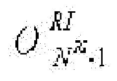
- For example, when the number of bits for transmitting channel RI is three (i.e., NRI=3), a 3-bit channel RI bit string [

FIG. 2 between values of {1, 2, 3, 4, 5, 6, 7, 8} that the RI of a downlink channel matrix can have and channel RI bit strings. In other words, this case is the same as the mapping relation exemplified in the first example embodiment. Also, when the number of bits for transmitting channel RI is four or more, a channel RI bit string may be mapped in a similar way as illustrated inFIG. 2 . - Next, the Reed-Muller coding step (S320) may be performed as will be described below.
- The above-mentioned Reed-Muller coding may be expressed by
Expression 4 below and a basis sequence illustrated inFIG. 4 that will be described later.
- Here,

-
FIG. 4 is a table showing an example of a basis sequence that can be applied to Reed-Muller coding of channel RI in the method of transmitting channel RI according to the second example embodiment of the present invention. - In the transmission method according to an example embodiment of the present invention, channel RI is Reed-Muller coded using a basis sequence having a 32-bit code length.
Expression 4 above expresses Reed-Muller coding together with a process of generating a bit sequence to be transmitted by circular repetition. - In other words, QRI denotes the number of bits to be transmitted through a wireless link and is determined according to the number of modulation symbols and a modulation order to be used to transmit a channel RI bit string through a PUSCH. When NRI channel rank bits are Reed-Muller coded into a bit sequence having a length of 32 bits, the coded bit sequences having a length of 32 bits are concatenated in a length of QRI and rate-matched. For example, when QRI is 100, a Reed-Muller coded 32-bit bit sequence is repeated three times, and last four (=100-32×3) bits may be the foremost four bits of the Reed-Muller coded bit sequence.
- In other words, in a method of encoding channel RI according to an example embodiment of the present invention, linear combination is applied to three or more channel RI bits to perform encoding.
- Finally, in the modulation symbol generating step (S330), the bit sequence that has been Reed-Muller coded and rate-matched is applied to a modulation mapper to generate modulation symbols, and the generated modulation symbols are mapped to resource locations designated in a PUSCH and transmitted.
- Using a method of transmitting downlink channel RI through a PUSCH according to example embodiments of the present invention, the channel RI can be efficiently encoded and transmitted even if three or more channel RI bits are required to transmit the downlink channel RI.
- In particular, a method of transmitting downlink channel RI according to example embodiments of the present invention can be employed when five or more antennas are required for downlink transmission or several carrier bands are used by carrier aggregation as specified in 3GPP LTE-advanced following
3GPP LTE release 10. - While the example embodiments of the present invention and their advantages have been described in detail, it should be understood that various changes, substitutions and alterations may be made herein without departing from the scope of the invention.
- According to one embodiment, provided is a method of transmitting channel rank information (RI) when the number of bits for transmitting the channel RI to be transmitted through a physical uplink shared channel (PUSCH) is three or more. The method includes mapping channel RI to be transmitted to a channel RI bit string of 3 bits or more, Reed-Muller coding and rate-matching the channel RI bit string using a basis sequence having a 32-bit code length, and generating modulation symbols by applying the bit sequence that has been Reed-Muller coded and rate-matched to a modulation mapper. Accordingly, the method of transmitting downlink channel RI can be employed when five or more antennas are used for downlink transmission or several carrier bands are used by carrier aggregation as specified in Third Generation Partnership Project (3GPP) long term evolution (LTE)-advanced following
3GPP LTE release 10. - Further embodiments of the application are disclosed in the following examples:
Example 1. A method of transmitting channel rank information (RI) when a number of bits for transmitting the channel RI to be transmitted through a physical uplink shared channel (PUSCH) is three, the method comprising: - mapping the channel RI (one value of {1, 2, 3, 4, 5, 6, 7, 8}) to be transmitted to a 3-bit channel RI bit string [

- repeatedly mapping the 3-bit channel RI bit string to modulation symbols in sequence according to a modulation order.
- mapping the channel RI to be transmitted to a channel RI bit string of 3 bits or more;
- Reed-Muller coding the channel RI bit string using a basis sequence having a 32-bit code length; and
- generating modulation symbols by applying the Reed-Muller coded bit sequence to a modulation mapper.
- map rank indication (RI) to a set of bits, the set of bits comprising NRI bits

- encode the set of bits to generate a set of coded bits;
- generate modulated symbols based on the set of encoded bits; and
- cause the communication apparatus to transmit the modulated symbols,

 | |
| 0, 0, 0 | 1 |
| 0, 0, 1 | 2 |
| 0, 1, 0 | 3 |
| 0, 1, 1 | 4 |
| 1, 0, 0 | 5 |
| 1, 0, 1 | 6 |
| 1, 1, 0 | 7 |
| 1, 1, 1 | 8 |


Example 4. The method of example 1, wherein repeatedly mapping the 3-bit channel RI bit string includes repeatedly modulating and mapping the 3-bit channel RI bit string in the form of [


where x is a placeholder maximizing a Euclidean distance between the modulation symbols.
Example 5. The method of example 1, wherein repeatedly mapping the 3-bit channel RI bit string includes repeatedly modulating and mapping the 3-bit channel RI bit string in the form of [


where x is a placeholder maximizing a Euclidean distance between the modulation symbols.
Example 6. A method of transmitting channel rank information (RI) when a number of bits for transmitting the channel RI to be transmitted through a physical uplink shared channel (PUSCH) is three or more, the method comprising:

 | |
| 0, 0, 0 | 1 |
| 0, 0, 1 | 2 |
| 0, 1, 0 | 3 |
| 0, 1, 1 | 4 |
| 1, 0, 0 | 5 |
| 1, 0, 1 | 6 |
| 1, 1, 0 | 7 |
| 1, 1, 1 | 8 |


Example 9. The method of example 8, wherein the basis sequence Mi,n is defined by the following table:
| i | Mi,0 | Mi,1 | Mi,2 | Mi,3 | Mi,4 | Mi,5 | Mi,6 | Mi,7 | Mi,8 | Mi,9 | Mi,10 |
| 0 | 1 | 1 | 0 | 0 | 0 | 0 | 0 | 0 | 0 | 0 | 1 |
| 1 | 1 | 1 | 1 | 0 | 0 | 0 | 0 | 0 | 0 | 1 | 1 |
| 2 | 1 | 0 | 0 | 1 | 0 | 0 | 1 | 0 | 1 | 1 | 1 |
| 3 | 1 | 0 | 1 | 1 | 0 | 0 | 0 | 0 | 1 | 0 | 1 |
| 4 | 1 | 1 | 1 | 1 | 0 | 0 | 0 | 1 | 0 | 0 | 1 |
| 5 | 1 | 1 | 0 | 0 | 1 | 0 | 1 | 1 | 1 | 0 | 1 |
| 6 | 1 | 0 | 1 | 0 | 1 | 0 | 1 | 0 | 1 | 1 | 1 |
| 7 | 1 | 0 | 0 | 1 | 1 | 0 | 0 | 1 | 1 | 0 | 1 |
| 8 | 1 | 1 | 0 | 1 | 1 | 0 | 0 | 1 | 0 | 1 | 1 |
| 9 | 1 | 0 | 1 | 1 | 1 | 0 | 1 | 0 | 0 | 1 | 1 |
| 10 | 1 | 0 | 1 | 0 | 0 | 1 | 1 | 1 | 0 | 1 | 1 |
| 11 | 1 | 1 | 1 | 0 | 0 | 1 | 1 | 0 | 1 | 0 | 1 |
| 12 | 1 | 0 | 0 | 1 | 0 | 1 | 0 | 1 | 1 | 1 | 1 |
| 13 | 1 | 1 | 0 | 1 | 0 | 1 | 0 | 1 | 0 | 1 | 1 |
| 14 | 1 | 0 | 0 | 0 | 1 | 1 | 0 | 1 | 0 | 0 | 1 |
| 15 | 1 | 1 | 0 | 0 | 1 | 1 | 1 | 1 | 0 | 1 | 1 |
| 18 | 1 | 1 | 1 | 0 | 1 | 1 | 1 | 0 | 0 | 1 | 0 |
| 17 | 1 | 0 | 0 | 1 | 1 | 1 | 0 | 0 | 1 | 0 | 0 |
| 18 | 1 | 1 | 0 | 1 | 1 | 1 | 1 | 1 | 0 | 0 | 0 |
| 19 | 1 | 0 | 0 | 0 | 0 | 1 | 1 | 0 | 0 | 0 | 0 |
| 20 | 1 | 0 | 1 | 0 | 0 | 0 | 1 | 0 | 0 | 0 | 1 |
| 21 | 1 | 1 | 0 | 1 | 0 | 0 | 0 | 0 | 0 | 1 | 1 |
| 22 | 1 | 0 | 0 | 0 | 1 | 0 | 0 | 1 | 1 | 0 | 1 |
| 23 | 1 | 1 | 1 | 0 | 1 | 0 | 0 | 0 | 1 | 1 | 1 |
| 24 | 1 | 1 | 1 | 1 | 1 | 0 | 1 | 1 | 1 | 1 | 0 |
| 25 | 1 | 1 | 0 | 0 | 0 | 1 | 1 | 1 | 0 | 0 | 1 |
| 28 | 1 | 0 | 1 | 1 | 0 | 1 | 0 | 0 | 1 | 1 | 0 |
| 27 | 1 | 1 | 1 | 1 | 0 | 1 | 0 | 1 | 1 | 1 | 0 |
| 28 | 1 | 0 | 1 | 0 | 1 | 1 | 1 | 0 | 1 | 0 | 0 |
| 29 | 1 | 0 | 1 | 1 | 1 | 1 | 1 | 1 | 1 | 0 | 0 |
| 30 | 1 | 1 | 1 | 1 | 1 | 1 | 1 | 1 | 1 | 1 | 1 |
| 31 | 1 | 0 | 0 | 0 | 0 | 0 | 0 | 0 | 0 | 0 | 0 |
mapping rank indication (RI) to a set of bits, the set of bits comprising NRI bits

encoding the set of bits to generate a set of coded bits;
generating modulated symbols based on the set of encoded bits; and
transmitting the modulated symbols,
wherein the encoding is performed by the following expression:
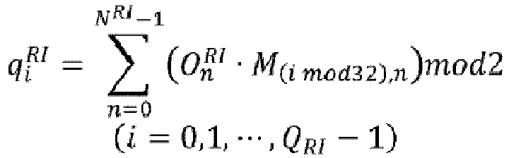
where

| i | Mi, 0 | Mi, 1 | Mi, 2 | Mi, 3 | Mi, 4 | Mi, 5 | Mi, 6 | Mi, 7 | Mi, 8 | Mi, 9 | Mi, 10 |
| 0 | 1 | 1 | 0 | 0 | 0 | 0 | 0 | 0 | 0 | 0 | 1 |
| 1 | 1 | 1 | 1 | 0 | 0 | 0 | 0 | 0 | 0 | 1 | 1 |
| 2 | 1 | 0 | 0 | 1 | 0 | 0 | 1 | 0 | 1 | 1 | 1 |
| 3 | 1 | 0 | 1 | 1 | 0 | 0 | 0 | 0 | 1 | 0 | 1 |
| 4 | 1 | 1 | 1 | 1 | 0 | 0 | 0 | 1 | 0 | 0 | 1 |
| 5 | 1 | 1 | 0 | 0 | 1 | 0 | 1 | 1 | 1 | 0 | 1 |
| 6 | 1 | 0 | 1 | 0 | 1 | 0 | 1 | 0 | 1 | 1 | 1 |
| 7 | 1 | 0 | 0 | 1 | 1 | 0 | 0 | 1 | 1 | 0 | 1 |
| 8 | 1 | 1 | 0 | 1 | 1 | 0 | 0 | 1 | 0 | 1 | 1 |
| 9 | 1 | 0 | 1 | 1 | 1 | 0 | 1 | 0 | 0 | 1 | 1 |
| 10 | 1 | 0 | 1 | 0 | 0 | 1 | 1 | 1 | 0 | 1 | 1 |
| 11 | 1 | 1 | 1 | 0 | 0 | 1 | 1 | 0 | 1 | 0 | 1 |
| 12 | 1 | 0 | 0 | 1 | 0 | 1 | 0 | 1 | 1 | 1 | 1 |
| 13 | 1 | 1 | 0 | 1 | 0 | 1 | 0 | 1 | 0 | 1 | 1 |
| 14 | 1 | 0 | 0 | 0 | 1 | 1 | 0 | 1 | 0 | 0 | 1 |
| 15 | 1 | 1 | 0 | 0 | 1 | 1 | 1 | 1 | 0 | 1 | 1 |
| 16 | 1 | 1 | 1 | 0 | 1 | 1 | 1 | 0 | 0 | 1 | 0 |
| 17 | 1 | 0 | 0 | 1 | 1 | 1 | 0 | 0 | 1 | 0 | 0 |
| 18 | 1 | 1 | 0 | 1 | 1 | 1 | 1 | 1 | 0 | 0 | 0 |
| 19 | 1 | 0 | 0 | 0 | 0 | 1 | 1 | 0 | 0 | 0 | 0 |
| 20 | 1 | 0 | 1 | 0 | 0 | 0 | 1 | 0 | 0 | 0 | 1 |
| 21 | 1 | 1 | 0 | 1 | 0 | 0 | 0 | 0 | 0 | 1 | 1 |
| 22 | 1 | 0 | 0 | 0 | 1 | 0 | 0 | 1 | 1 | 0 | 1 |
| 23 | 1 | 1 | 1 | 0 | 1 | 0 | 0 | 0 | 1 | 1 | 1 |
| 24 | 1 | 1 | 1 | 1 | 1 | 0 | 1 | 1 | 1 | 1 | 0 |
| 25 | 1 | 1 | 0 | 0 | 0 | 1 | 1 | 1 | 0 | 0 | 1 |
| 26 | 1 | 0 | 1 | 1 | 0 | 1 | 0 | 0 | 1 | 1 | 0 |
| 27 | 1 | 1 | 1 | 1 | 0 | 1 | 0 | 1 | 1 | 1 | 0 |
| 28 | 1 | 0 | 1 | 0 | 1 | 1 | 1 | 0 | 1 | 0 | 0 |
| 29 | 1 | 0 | 1 | 1 | 1 | 1 | 1 | 1 | 1 | 0 | 0 |
| 30 | 1 | 1 | 1 | 1 | 1 | 1 | 1 | 1 | 1 | 1 | 1 |
| 31 | 1 | 0 | 0 | 0 | 0 | 0 | 0 | 0 | 0 | 0 | 0 |
Example 12. The method of example 10, wherein the modulated symbols are transmitted through a physical uplink shard channel (PUSCH).
Example 13. The method of Example 10, wherein the modulated symbols comprises the set of coded bits, and the set of coded bits are repeated in the modulated symbols.
14. A communication apparatus comprising:
a memory; and
a processor operably couple to the memory,
wherein the processor, when executing program instructions stored in the memory, is configured to:

where

| i | Mi, 0 | Mi, 1 | Mi, 2 | Mi, 3 | Mi, 4 | Mi, 5 | Mi, 6 | Mi, 7 | Mi, 9 | Mi, 9 | Mi, 10 |
| 0 | 1 | 1 | 0 | 0 | 0 | 0 | 0 | 0 | 0 | 0 | 1 |
| 1 | 1 | 1 | 1 | 0 | 0 | 0 | 0 | 0 | 0 | 1 | 1 |
| 2 | 1 | 0 | 0 | 1 | 0 | 0 | 1 | 0 | 1 | 1 | 1 |
| 3 | 1 | 0 | 1 | 1 | 0 | 0 | 0 | 0 | 1 | 0 | 1 |
| 4 | 1 | 1 | 1 | 1 | 0 | 0 | 0 | 1 | 0 | 0 | 1 |
| 5 | 1 | 1 | 0 | 0 | 1 | 0 | 1 | 1 | 1 | 0 | 1 |
| 6 | 1 | 0 | 1 | 0 | 1 | 0 | 1 | 0 | 1 | 1 | 1 |
| 7 | 1 | 0 | 0 | 1 | 1 | 0 | 0 | 1 | 1 | 0 | 1 |
| 8 | 1 | 1 | 0 | 1 | 1 | 0 | 0 | 1 | 0 | 1 | 1 |
| 9 | 1 | 0 | 1 | 1 | 1 | 0 | 1 | 0 | 0 | 1 | 1 |
| 10 | 1 | 0 | 1 | 0 | 0 | 1 | 1 | 1 | 0 | 1 | 1 |
| 11 | 1 | 1 | 1 | 0 | 0 | 1 | 1 | 0 | 1 | 0 | 1 |
| 12 | 1 | 0 | 0 | 1 | 0 | 1 | 0 | 1 | 1 | 1 | 1 |
| 13 | 1 | 1 | 0 | 1 | 0 | 1 | 0 | 1 | 0 | 1 | 1 |
| 14 | 1 | 0 | 0 | 0 | 1 | 1 | 0 | 1 | 0 | 0 | 1 |
| 15 | 1 | 1 | 0 | 0 | 1 | 1 | 1 | 1 | 0 | 1 | 1 |
| 16 | 1 | 1 | 1 | 0 | 1 | 1 | 1 | 0 | 0 | 1 | 0 |
| 17 | 1 | 0 | 0 | 1 | 1 | 1 | 0 | 0 | 1 | 0 | 0 |
| 18 | 1 | 1 | 0 | 1 | 1 | 1 | 1 | 1 | 0 | 0 | 0 |
| 19 | 1 | 0 | 0 | 0 | 0 | 1 | 1 | 0 | 0 | 0 | 0 |
| 20 | 1 | 0 | 1 | 0 | 0 | 0 | 1 | 0 | 0 | 0 | 1 |
| 21 | 1 | 1 | 0 | 1 | 0 | 0 | 0 | 0 | 0 | 1 | 1 |
| 22 | 1 | 0 | 0 | 0 | 1 | 0 | 0 | 1 | 1 | 0 | 1 |
| 23 | 1 | 1 | 1 | 0 | 1 | 0 | 0 | 0 | 1 | 1 | 1 |
| 24 | 1 | 1 | 1 | 1 | 1 | 0 | 1 | 1 | 1 | 1 | 0 |
| 25 | 1 | 1 | 0 | 0 | 0 | 1 | 1 | 1 | 0 | 0 | 1 |
| 26 | 1 | 0 | 1 | 1 | 0 | 1 | 0 | 0 | 1 | 1 | 0 |
| 27 | 1 | 1 | 1 | 1 | 0 | 1 | 0 | 1 | 1 | 1 | 0 |
| 28 | 1 | 0 | 1 | 0 | 1 | 1 | 1 | 0 | 1 | 0 | 0 |
| 29 | 1 | 0 | 1 | 1 | 1 | 1 | 1 | 1 | 1 | 0 | 0 |
| 30 | 1 | 1 | 1 | 1 | 1 | 1 | 1 | 1 | 1 | 1 | 1 |
| 31 | 1 | 0 | 0 | 0 | 0 | 0 | 0 | 0 | 0 | 0 | 0 |
Example 16. The apparatus of example 14, wherein the modulated symbols are transmitted through a physical uplink shard channel (PUSCH).
Example 17. The apparatus of
Claims (10)
- A communication method, the method comprising:generating, by a terminal, a first sequence comprising a first set of bits based on first information, wherein the first set of bits comprises a first number of bits;generating, by the terminal, a second sequence comprising a second set of bits based on the first sequence;generating, by the terminal, symbols based on the second sequence; andtransmitting, by the terminal, the symbols,wherein the second sequence is generated based on a following expression:
 wherein B is a positive integer, on denotes the first sequence, bi denotes the second sequence, O denotes the first number, and Mi,n denotes a sequence of bits defined by Table 1:
Table 1 i Mi, 0 Mi, 1 Mi, 2 Mi, 3 Mi, 4 Mi, 5 Mi, 6 Mi, 7 Mi, 8 Mi, 9 Mi, 10 0 1 1 0 0 0 0 0 0 0 0 1 1 1 1 1 0 0 0 0 0 0 1 1 2 1 0 0 1 0 0 1 0 1 1 1 3 1 0 1 1 0 0 0 0 1 0 1 4 1 1 1 1 0 0 0 1 0 0 1 5 1 1 0 0 1 0 1 1 1 0 1 6 1 0 1 0 1 0 1 0 1 1 1 7 1 0 0 1 1 0 0 1 1 0 1 8 1 1 0 1 1 0 0 1 0 1 1 9 1 0 1 1 1 0 1 0 0 1 1 10 1 0 1 0 0 1 1 1 0 1 1 11 1 1 1 0 0 1 1 0 1 0 1 12 1 0 0 1 0 1 0 1 1 1 1 13 1 1 0 1 0 1 0 1 0 1 1 14 1 0 0 0 1 1 0 1 0 0 1 15 1 1 0 0 1 1 1 1 0 1 1 16 1 1 1 0 1 1 1 0 0 1 0 17 1 0 0 1 1 1 0 0 1 0 0 18 1 1 0 1 1 1 1 1 0 0 0 19 1 0 0 0 0 1 1 0 0 0 0 20 1 0 1 0 0 0 1 0 0 0 1 21 1 1 0 1 0 0 0 0 0 1 1 22 1 0 0 0 1 0 0 1 1 0 1 23 1 1 1 0 1 0 0 0 1 1 1 24 1 1 1 1 1 0 1 1 1 1 0 25 1 1 0 0 0 1 1 1 0 0 1 26 1 0 1 1 0 1 0 0 1 1 0 27 1 1 1 1 0 1 0 1 1 1 0 28 1 0 1 0 1 1 1 0 1 0 0 29 1 0 1 1 1 1 1 1 1 0 0 30 1 1 1 1 1 1 1 1 1 1 1 31 1 0 0 0 0 0 0 0 0 0 0 - The method of claim 1, wherein the first information comprises rank information (Rl).
- The method of claim 1, wherein the symbols are transmitted through physical uplink shared channel (PUSCH).
- The method of claim 1, wherein the first number is three (3), and the first sequence is generated based on the first information according to Table 2:
Table 2 First sequence First information [0, 0, 0] 1 [0, 0, 1] 2 [0, 1, 0] 3 [0, 1, 1] 4 [1, 0, 0] 5 [1, 0, 1] 6 [1, 1, 0] 7 [1, 1, 1] 8 - The method of claim 1, wherein generating the symbols comprises:generating, by the terminal, a third sequence in which the second sequence is repeated at least twice; andgenerating, by the terminal, the symbols based on the third sequence.
- A communication apparatus, comprising:a circuitry which is configured to:generate a first sequence comprising a first set of bits based on first information, wherein the first set of bits comprises a first number of bits;generate a second sequence comprising a second set of bits based on the first sequence;generate symbols based on the second sequence; andcause the communication apparatus to transmit the symbols,wherein the second sequence is generated based on a following expression:
 wherein B is a positive integer, on denotes the first sequence, bi denotes the second sequence, O denotes the first number, and M i,n denotes a sequence of bits defined by Table 1:
Table 1 i Mi, 0 Mi, 1 Mi, 2 Mi, 3 Mi, 4 Mi, 5 Mi, 6 Mi, 7 Mi, 8 Mi, 9 Mi, 10 0 1 1 0 0 0 0 0 0 0 0 1 1 1 1 1 0 0 0 0 0 0 1 1 2 1 0 0 1 0 0 1 0 1 1 1 3 1 0 1 1 0 0 0 0 1 0 1 4 1 1 1 1 0 0 0 1 0 0 1 5 1 1 0 0 1 0 1 1 1 0 1 6 1 0 1 0 1 0 1 0 1 1 1 7 1 0 0 1 1 0 0 1 1 0 1 8 1 1 0 1 1 0 0 1 0 1 1 9 1 0 1 1 1 0 1 0 0 1 1 10 1 0 1 0 0 1 1 1 0 1 1 11 1 1 1 0 0 1 1 0 1 0 1 12 1 0 0 1 0 1 0 1 1 1 1 13 1 1 0 1 0 1 0 1 0 1 1 14 1 0 0 0 1 1 0 1 0 0 1 15 1 1 0 0 1 1 1 1 0 1 1 16 1 1 1 0 1 1 1 0 0 1 0 17 1 0 0 1 1 1 0 0 1 0 0 18 1 1 0 1 1 1 1 1 0 0 0 19 1 0 0 0 0 1 1 0 0 0 0 20 1 0 1 0 0 0 1 0 0 0 1 21 1 1 0 1 0 0 0 0 0 1 1 22 1 0 0 0 1 0 0 1 1 0 1 23 1 1 1 0 1 0 0 0 1 1 1 24 1 1 1 1 1 0 1 1 1 1 0 25 1 1 0 0 0 1 1 1 0 0 1 26 1 0 1 1 0 1 0 0 1 1 0 27 1 1 1 1 0 1 0 1 1 1 0 28 1 0 1 0 1 1 1 0 1 0 0 29 1 0 1 1 1 1 1 1 1 0 0 30 1 1 1 1 1 1 1 1 1 1 1 31 1 0 0 0 0 0 0 0 0 0 0 - The communication apparatus of claim 6, wherein the first information comprises rank information (Rl).
- The communication apparatus of claim 6, wherein the symbols are transmitted through physical uplink shared channel (PUSCH).
- The communication apparatus of claim 6, wherein the first number is three (3), and the first sequence is generated based on the first information according to Table 2:
Table 2 First sequence First information [0, 0, 0] 1 [0, 0, 1] 2 [0, 1, 0] 3 [0, 1, 1] 4 [1, 0, 0] 5 [1, 0, 1] 6 [1, 1, 0] 7 [1, 1, 1] 8 - The communication apparatus of claim 6, wherein the circuitry is configured, in generating the symbols, to:generate a third sequence in which the second sequence is repeated at least twice; andgenerate the symbols based on the third sequence.
Applications Claiming Priority (4)
| Application Number | Priority Date | Filing Date | Title |
|---|---|---|---|
| KR20100043844 | 2010-05-11 | ||
| EP11165420.8A EP2387172B1 (en) | 2010-05-11 | 2011-05-10 | Method of transmitting downlink channel rank information through physical uplink shared channel |
| EP22185375.7A EP4117210B1 (en) | 2010-05-11 | 2011-05-10 | Method of transmitting downlink channel rank information through physical uplink shared channel |
| EP19175889.5A EP3565153B1 (en) | 2010-05-11 | 2011-05-10 | Method of transmitting downlink channel rank information through physical uplink shared channel |
Related Parent Applications (4)
| Application Number | Title | Priority Date | Filing Date |
|---|---|---|---|
| EP11165420.8A Division EP2387172B1 (en) | 2010-05-11 | 2011-05-10 | Method of transmitting downlink channel rank information through physical uplink shared channel |
| EP22185375.7A Division EP4117210B1 (en) | 2010-05-11 | 2011-05-10 | Method of transmitting downlink channel rank information through physical uplink shared channel |
| EP22185375.7A Division-Into EP4117210B1 (en) | 2010-05-11 | 2011-05-10 | Method of transmitting downlink channel rank information through physical uplink shared channel |
| EP19175889.5A Division EP3565153B1 (en) | 2010-05-11 | 2011-05-10 | Method of transmitting downlink channel rank information through physical uplink shared channel |
Publications (3)
| Publication Number | Publication Date |
|---|---|
| EP4333321A2 true EP4333321A2 (en) | 2024-03-06 |
| EP4333321A3 EP4333321A3 (en) | 2024-05-22 |
| EP4333321B1 EP4333321B1 (en) | 2025-11-12 |
Family
ID=44279915
Family Applications (4)
| Application Number | Title | Priority Date | Filing Date |
|---|---|---|---|
| EP23218040.6A Active EP4333321B1 (en) | 2010-05-11 | 2011-05-10 | Method of transmitting downlink channel rank information through physical uplink shared channel |
| EP11165420.8A Active EP2387172B1 (en) | 2010-05-11 | 2011-05-10 | Method of transmitting downlink channel rank information through physical uplink shared channel |
| EP19175889.5A Active EP3565153B1 (en) | 2010-05-11 | 2011-05-10 | Method of transmitting downlink channel rank information through physical uplink shared channel |
| EP22185375.7A Active EP4117210B1 (en) | 2010-05-11 | 2011-05-10 | Method of transmitting downlink channel rank information through physical uplink shared channel |
Family Applications After (3)
| Application Number | Title | Priority Date | Filing Date |
|---|---|---|---|
| EP11165420.8A Active EP2387172B1 (en) | 2010-05-11 | 2011-05-10 | Method of transmitting downlink channel rank information through physical uplink shared channel |
| EP19175889.5A Active EP3565153B1 (en) | 2010-05-11 | 2011-05-10 | Method of transmitting downlink channel rank information through physical uplink shared channel |
| EP22185375.7A Active EP4117210B1 (en) | 2010-05-11 | 2011-05-10 | Method of transmitting downlink channel rank information through physical uplink shared channel |
Country Status (5)
| Country | Link |
|---|---|
| US (2) | US8599781B2 (en) |
| EP (4) | EP4333321B1 (en) |
| KR (1) | KR101220075B1 (en) |
| ES (4) | ES2930153T3 (en) |
| PL (4) | PL2387172T3 (en) |
Families Citing this family (7)
| Publication number | Priority date | Publication date | Assignee | Title |
|---|---|---|---|---|
| EP4333321B1 (en) * | 2010-05-11 | 2025-11-12 | Electronics And Telecommunications Research Institute | Method of transmitting downlink channel rank information through physical uplink shared channel |
| CN104054292B (en) | 2012-01-15 | 2017-05-10 | Lg电子株式会社 | Method and apparatus for transmitting control information through uplink |
| KR102117024B1 (en) * | 2012-11-28 | 2020-06-01 | 삼성전자 주식회사 | Method and apparatus for communication in wireless communication system |
| KR102426780B1 (en) * | 2015-03-02 | 2022-07-29 | 삼성전자주식회사 | Transmitter and parity permutation method thereof |
| CN111917518B (en) | 2015-03-02 | 2023-04-14 | 三星电子株式会社 | sending method |
| CN107437984B (en) * | 2016-05-27 | 2020-11-10 | 华为技术有限公司 | Information transmission method and device |
| CN120419146A (en) * | 2023-01-16 | 2025-08-01 | Qorvo美国公司 | System and method for encoding physical layer header in wireless communication |
Citations (1)
| Publication number | Priority date | Publication date | Assignee | Title |
|---|---|---|---|---|
| KR20100043844A (en) | 2008-10-21 | 2010-04-29 | 주식회사 테스 | Plasma processing apparatus |
Family Cites Families (23)
| Publication number | Priority date | Publication date | Assignee | Title |
|---|---|---|---|---|
| US8755806B2 (en) | 2008-02-08 | 2014-06-17 | Texas Instruments Incorporated | Transmission of feedback information on PUSCH in wireless networks |
| US8045508B2 (en) | 2008-02-14 | 2011-10-25 | Lg Electronics Inc. | Rank feedback method for multiple-input multiple-output transmission |
| KR101430476B1 (en) * | 2008-03-24 | 2014-08-18 | 엘지전자 주식회사 | A method for transmitting and receiving precoded signal in MIMO communication system |
| US8154983B2 (en) | 2008-03-25 | 2012-04-10 | Samsung Electronics Co., Ltd. | System and method for the placement of rank information in a physical uplink shared channel |
| US8345794B2 (en) | 2008-04-29 | 2013-01-01 | Qualcomm Incorporated | Encoded control channel information interleaving |
| KR100925444B1 (en) | 2008-05-27 | 2009-11-06 | 엘지전자 주식회사 | Method of transmitting an uplink signal including data and control information through an uplink channel |
| KR101638900B1 (en) * | 2008-08-05 | 2016-07-12 | 엘지전자 주식회사 | Method of transmitting control information information of downlink multi carriers in a wireless communication system |
| CN101340442B (en) * | 2008-08-07 | 2012-10-10 | 中兴通讯股份有限公司 | Information multiplexing method |
| KR101646249B1 (en) * | 2008-08-11 | 2016-08-16 | 엘지전자 주식회사 | Method and apparatus of transmitting information in wireless communication system |
| KR101521001B1 (en) * | 2010-01-08 | 2015-05-15 | 인터디지탈 패튼 홀딩스, 인크 | Channel state information transmission for multiple carriers |
| KR101733489B1 (en) * | 2010-01-17 | 2017-05-24 | 엘지전자 주식회사 | Apparatus and method of transmitting control information in wireless communication system |
| WO2011136559A2 (en) * | 2010-04-27 | 2011-11-03 | 엘지전자 주식회사 | Method and apparatus for transmitting uplink control information in a wireless communication system |
| EP2567558B1 (en) * | 2010-05-07 | 2014-07-30 | Huawei Technologies Co., Ltd. | Method and system for quantized feedback rate adaptation in a communication system |
| EP4333321B1 (en) * | 2010-05-11 | 2025-11-12 | Electronics And Telecommunications Research Institute | Method of transmitting downlink channel rank information through physical uplink shared channel |
| US9160486B2 (en) * | 2010-05-13 | 2015-10-13 | Lg Electronics Inc. | Method and apparatus for multiplexing control information and data, and for transmitting the multiplexed control information and data in a MIMO wireless communication system |
| EP2421187B1 (en) * | 2010-08-20 | 2018-02-28 | LG Electronics Inc. | Method for transmitting control information in a wireless communication system and apparatus therefor |
| EP2421185B1 (en) * | 2010-08-20 | 2019-07-03 | LG Electronics Inc. | Method for transmitting control information in a wireless communication system and apparatus therefor |
| EP2421186A3 (en) * | 2010-08-20 | 2014-11-26 | LG Electronics Inc. | Method for transmitting control information in a wireless communication system and apparatus therefor |
| US8848557B2 (en) * | 2010-08-25 | 2014-09-30 | Samsung Electronics Co., Ltd. | Multiplexing of control and data in UL MIMO system based on SC-FDM |
| WO2012039571A2 (en) * | 2010-09-20 | 2012-03-29 | Lg Electronics Inc. | Method and user equipment for transmitting uplink control information |
| US20140016546A1 (en) * | 2010-10-10 | 2014-01-16 | Lg Electronics Inc. | Method and device for transmitting uplink control information in wireless access system |
| US9819464B2 (en) * | 2010-11-02 | 2017-11-14 | Lg Electronics Inc. | Technique to provide channel format and signal processing for efficiently transmitting control information |
| EP2490362B1 (en) * | 2011-02-15 | 2018-04-04 | LG Electronics Inc. | Method and apparatus for transmitting channel quality control information in wireless access system |
-
2011
- 2011-05-10 EP EP23218040.6A patent/EP4333321B1/en active Active
- 2011-05-10 ES ES19175889T patent/ES2930153T3/en active Active
- 2011-05-10 PL PL11165420T patent/PL2387172T3/en unknown
- 2011-05-10 PL PL19175889.5T patent/PL3565153T3/en unknown
- 2011-05-10 EP EP11165420.8A patent/EP2387172B1/en active Active
- 2011-05-10 ES ES11165420T patent/ES2749970T3/en active Active
- 2011-05-10 EP EP19175889.5A patent/EP3565153B1/en active Active
- 2011-05-10 PL PL23218040.6T patent/PL4333321T3/en unknown
- 2011-05-10 ES ES22185375T patent/ES2981649T3/en active Active
- 2011-05-10 PL PL22185375.7T patent/PL4117210T3/en unknown
- 2011-05-10 EP EP22185375.7A patent/EP4117210B1/en active Active
- 2011-05-10 ES ES23218040T patent/ES3062020T3/en active Active
- 2011-05-11 KR KR1020110043885A patent/KR101220075B1/en active Active
- 2011-05-11 US US13/105,428 patent/US8599781B2/en not_active Ceased
-
2015
- 2015-12-03 US US14/958,500 patent/USRE48101E1/en active Active
Patent Citations (1)
| Publication number | Priority date | Publication date | Assignee | Title |
|---|---|---|---|---|
| KR20100043844A (en) | 2008-10-21 | 2010-04-29 | 주식회사 테스 | Plasma processing apparatus |
Also Published As
| Publication number | Publication date |
|---|---|
| PL3565153T3 (en) | 2022-12-12 |
| PL4333321T3 (en) | 2026-03-23 |
| EP4333321B1 (en) | 2025-11-12 |
| EP3565153A1 (en) | 2019-11-06 |
| EP2387172A3 (en) | 2014-11-26 |
| EP2387172A2 (en) | 2011-11-16 |
| USRE48101E1 (en) | 2020-07-14 |
| ES2930153T3 (en) | 2022-12-07 |
| ES3062020T3 (en) | 2026-04-08 |
| EP4117210B1 (en) | 2024-03-20 |
| PL4117210T3 (en) | 2024-06-24 |
| ES2749970T3 (en) | 2020-03-24 |
| KR101220075B1 (en) | 2013-01-21 |
| US8599781B2 (en) | 2013-12-03 |
| US20110299482A1 (en) | 2011-12-08 |
| ES2981649T3 (en) | 2024-10-09 |
| EP3565153B1 (en) | 2022-08-24 |
| PL2387172T3 (en) | 2020-01-31 |
| EP4117210A1 (en) | 2023-01-11 |
| EP4333321A3 (en) | 2024-05-22 |
| KR20110124726A (en) | 2011-11-17 |
| EP2387172B1 (en) | 2019-07-24 |
Similar Documents
| Publication | Publication Date | Title |
|---|---|---|
| USRE48101E1 (en) | Method of transmitting downlink channel rank information through physical uplink shared channel | |
| US8140944B2 (en) | Interleaver design with unequal error protection for control information | |
| EP3413492B1 (en) | Method, device and system for determining transmission parameters of data sharing channel | |
| EP3755070B1 (en) | Method and apparatus for transmitting uplink control channel | |
| US9459954B2 (en) | Feedback signaling error detection and checking in MIMO wireless communication systems | |
| CN101924606B (en) | Method for sending uplink control information on basis of PUSCH transmission and system thereof | |
| US10897329B2 (en) | Method and apparatus for performing HARQ on basis of polar code | |
| EP3429114B1 (en) | Information processing method, terminal device, network device, and communication system | |
| EP4224754A1 (en) | Data communication processing method and device | |
| CN103188033B (en) | The method of coding ascending control information and device | |
| EP2572464B1 (en) | System and method for signaling control information in a mobile communication network | |
| EP3100426B1 (en) | 256 quadrature amplitude modulation user equipment category handling | |
| CN105207743A (en) | Uplink transmission apparatus and method for mobile communication system supporting uplink mimo | |
| EP3100425B1 (en) | 256 quadrature amplitude modulation user equipment category handling | |
| CN101702632B (en) | Periodic channel state information feedback method and system | |
| US9210696B2 (en) | Method and apparatus for processing UCI and method for transmission thereof based on MIMO system | |
| CN111357205B (en) | Method and apparatus for performing encoding and decoding in a wireless communication system | |
| CN102377509B (en) | Control information transmitting method, control information receiving method and control information receiving equipment | |
| EP2811780B1 (en) | Data transmission method and system, base station and user equipment | |
| CN102546119B (en) | Information bit sending method, device and system | |
| CN102215081B (en) | Coding method and device for controlling control information transmitted on channel |
Legal Events
| Date | Code | Title | Description |
|---|---|---|---|
| PUAI | Public reference made under article 153(3) epc to a published international application that has entered the european phase |
Free format text: ORIGINAL CODE: 0009012 |
|
| STAA | Information on the status of an ep patent application or granted ep patent |
Free format text: STATUS: THE APPLICATION HAS BEEN PUBLISHED |
|
| AC | Divisional application: reference to earlier application |
Ref document number: 2387172 Country of ref document: EP Kind code of ref document: P Ref document number: 3565153 Country of ref document: EP Kind code of ref document: P Ref document number: 4117210 Country of ref document: EP Kind code of ref document: P |
|
| AK | Designated contracting states |
Kind code of ref document: A2 Designated state(s): AL AT BE BG CH CY CZ DE DK EE ES FI FR GB GR HR HU IE IS IT LI LT LU LV MC MK MT NL NO PL PT RO RS SE SI SK SM TR |
|
| REG | Reference to a national code |
Ref country code: DE Ref legal event code: R079 Free format text: PREVIOUS MAIN CLASS: H04B0007060000 Ipc: H04L0001000000 Ref country code: DE Ref legal event code: R079 Ref document number: 602011075533 Country of ref document: DE Free format text: PREVIOUS MAIN CLASS: H04B0007060000 Ipc: H04L0001000000 |
|
| PUAL | Search report despatched |
Free format text: ORIGINAL CODE: 0009013 |
|
| AK | Designated contracting states |
Kind code of ref document: A3 Designated state(s): AL AT BE BG CH CY CZ DE DK EE ES FI FR GB GR HR HU IE IS IT LI LT LU LV MC MK MT NL NO PL PT RO RS SE SI SK SM TR |
|
| RIC1 | Information provided on ipc code assigned before grant |
Ipc: H04B 7/06 20060101ALI20240415BHEP Ipc: H04L 1/08 20060101ALI20240415BHEP Ipc: H04L 1/18 20230101ALI20240415BHEP Ipc: H04L 5/00 20060101ALI20240415BHEP Ipc: H04L 1/00 20060101AFI20240415BHEP |
|
| STAA | Information on the status of an ep patent application or granted ep patent |
Free format text: STATUS: REQUEST FOR EXAMINATION WAS MADE |
|
| 17P | Request for examination filed |
Effective date: 20241122 |
|
| RBV | Designated contracting states (corrected) |
Designated state(s): AL AT BE BG CH CY CZ DE DK EE ES FI FR GB GR HR HU IE IS IT LI LT LU LV MC MK MT NL NO PL PT RO RS SE SI SK SM TR |
|
| STAA | Information on the status of an ep patent application or granted ep patent |
Free format text: STATUS: EXAMINATION IS IN PROGRESS |
|
| 17Q | First examination report despatched |
Effective date: 20250116 |
|
| GRAP | Despatch of communication of intention to grant a patent |
Free format text: ORIGINAL CODE: EPIDOSNIGR1 |
|
| STAA | Information on the status of an ep patent application or granted ep patent |
Free format text: STATUS: GRANT OF PATENT IS INTENDED |
|
| INTG | Intention to grant announced |
Effective date: 20250606 |
|
| GRAS | Grant fee paid |
Free format text: ORIGINAL CODE: EPIDOSNIGR3 |
|
| GRAA | (expected) grant |
Free format text: ORIGINAL CODE: 0009210 |
|
| STAA | Information on the status of an ep patent application or granted ep patent |
Free format text: STATUS: THE PATENT HAS BEEN GRANTED |
|
| AC | Divisional application: reference to earlier application |
Ref document number: 4117210 Country of ref document: EP Kind code of ref document: P Ref document number: 3565153 Country of ref document: EP Kind code of ref document: P Ref document number: 2387172 Country of ref document: EP Kind code of ref document: P |
|
| AK | Designated contracting states |
Kind code of ref document: B1 Designated state(s): AL AT BE BG CH CY CZ DE DK EE ES FI FR GB GR HR HU IE IS IT LI LT LU LV MC MK MT NL NO PL PT RO RS SE SI SK SM TR |
|
| REG | Reference to a national code |
Ref country code: CH Ref legal event code: F10 Free format text: ST27 STATUS EVENT CODE: U-0-0-F10-F00 (AS PROVIDED BY THE NATIONAL OFFICE) Effective date: 20251112 Ref country code: GB Ref legal event code: FG4D |
|
| REG | Reference to a national code |
Ref country code: DE Ref legal event code: R096 Ref document number: 602011075533 Country of ref document: DE |
|
| REG | Reference to a national code |
Ref country code: IE Ref legal event code: FG4D |
|
| REG | Reference to a national code |
Ref country code: NL Ref legal event code: FP |
|
| REG | Reference to a national code |
Ref country code: ES Ref legal event code: FG2A Ref document number: 3062020 Country of ref document: ES Kind code of ref document: T3 Effective date: 20260408 |
|
| REG | Reference to a national code |
Ref country code: LT Ref legal event code: MG9D |
|
| PG25 | Lapsed in a contracting state [announced via postgrant information from national office to epo] |
Ref country code: NO Free format text: LAPSE BECAUSE OF FAILURE TO SUBMIT A TRANSLATION OF THE DESCRIPTION OR TO PAY THE FEE WITHIN THE PRESCRIBED TIME-LIMIT Effective date: 20260212 |
|
| PG25 | Lapsed in a contracting state [announced via postgrant information from national office to epo] |
Ref country code: HR Free format text: LAPSE BECAUSE OF FAILURE TO SUBMIT A TRANSLATION OF THE DESCRIPTION OR TO PAY THE FEE WITHIN THE PRESCRIBED TIME-LIMIT Effective date: 20251112 Ref country code: FI Free format text: LAPSE BECAUSE OF FAILURE TO SUBMIT A TRANSLATION OF THE DESCRIPTION OR TO PAY THE FEE WITHIN THE PRESCRIBED TIME-LIMIT Effective date: 20251112 Ref country code: AT Free format text: LAPSE BECAUSE OF FAILURE TO SUBMIT A TRANSLATION OF THE DESCRIPTION OR TO PAY THE FEE WITHIN THE PRESCRIBED TIME-LIMIT Effective date: 20251112 |
|
| REG | Reference to a national code |
Ref country code: AT Ref legal event code: MK05 Ref document number: 1857703 Country of ref document: AT Kind code of ref document: T Effective date: 20251112 |
|
| PG25 | Lapsed in a contracting state [announced via postgrant information from national office to epo] |
Ref country code: RS Free format text: LAPSE BECAUSE OF FAILURE TO SUBMIT A TRANSLATION OF THE DESCRIPTION OR TO PAY THE FEE WITHIN THE PRESCRIBED TIME-LIMIT Effective date: 20260212 |
|
| PG25 | Lapsed in a contracting state [announced via postgrant information from national office to epo] |
Ref country code: IS Free format text: LAPSE BECAUSE OF FAILURE TO SUBMIT A TRANSLATION OF THE DESCRIPTION OR TO PAY THE FEE WITHIN THE PRESCRIBED TIME-LIMIT Effective date: 20260312 |
|
| PG25 | Lapsed in a contracting state [announced via postgrant information from national office to epo] |
Ref country code: PT Free format text: LAPSE BECAUSE OF FAILURE TO SUBMIT A TRANSLATION OF THE DESCRIPTION OR TO PAY THE FEE WITHIN THE PRESCRIBED TIME-LIMIT Effective date: 20260312 |
|
| PG25 | Lapsed in a contracting state [announced via postgrant information from national office to epo] |
Ref country code: LV Free format text: LAPSE BECAUSE OF FAILURE TO SUBMIT A TRANSLATION OF THE DESCRIPTION OR TO PAY THE FEE WITHIN THE PRESCRIBED TIME-LIMIT Effective date: 20251112 |
|
| PG25 | Lapsed in a contracting state [announced via postgrant information from national office to epo] |
Ref country code: BG Free format text: LAPSE BECAUSE OF FAILURE TO SUBMIT A TRANSLATION OF THE DESCRIPTION OR TO PAY THE FEE WITHIN THE PRESCRIBED TIME-LIMIT Effective date: 20251112 |
|
| PGFP | Annual fee paid to national office [announced via postgrant information from national office to epo] |
Ref country code: NL Payment date: 20260421 Year of fee payment: 16 |
|
| PG25 | Lapsed in a contracting state [announced via postgrant information from national office to epo] |
Ref country code: LT Free format text: LAPSE BECAUSE OF FAILURE TO SUBMIT A TRANSLATION OF THE DESCRIPTION OR TO PAY THE FEE WITHIN THE PRESCRIBED TIME-LIMIT Effective date: 20251112 |
|
| PG25 | Lapsed in a contracting state [announced via postgrant information from national office to epo] |
Ref country code: SM Free format text: LAPSE BECAUSE OF FAILURE TO SUBMIT A TRANSLATION OF THE DESCRIPTION OR TO PAY THE FEE WITHIN THE PRESCRIBED TIME-LIMIT Effective date: 20251112 |
|
| PGFP | Annual fee paid to national office [announced via postgrant information from national office to epo] |
Ref country code: ES Payment date: 20260608 Year of fee payment: 16 |
|
| PG25 | Lapsed in a contracting state [announced via postgrant information from national office to epo] |
Ref country code: DK Free format text: LAPSE BECAUSE OF FAILURE TO SUBMIT A TRANSLATION OF THE DESCRIPTION OR TO PAY THE FEE WITHIN THE PRESCRIBED TIME-LIMIT Effective date: 20251112 |
|
| PGFP | Annual fee paid to national office [announced via postgrant information from national office to epo] |
Ref country code: GB Payment date: 20260424 Year of fee payment: 16 Ref country code: PL Payment date: 20260422 Year of fee payment: 16 |
|
| PGFP | Annual fee paid to national office [announced via postgrant information from national office to epo] |
Ref country code: IT Payment date: 20260421 Year of fee payment: 16 |
|
| PGFP | Annual fee paid to national office [announced via postgrant information from national office to epo] |
Ref country code: DE Payment date: 20260420 Year of fee payment: 16 |
|
| PG25 | Lapsed in a contracting state [announced via postgrant information from national office to epo] |
Ref country code: EE Free format text: LAPSE BECAUSE OF FAILURE TO SUBMIT A TRANSLATION OF THE DESCRIPTION OR TO PAY THE FEE WITHIN THE PRESCRIBED TIME-LIMIT Effective date: 20251112 |
|
| PG25 | Lapsed in a contracting state [announced via postgrant information from national office to epo] |
Ref country code: CZ Free format text: LAPSE BECAUSE OF FAILURE TO SUBMIT A TRANSLATION OF THE DESCRIPTION OR TO PAY THE FEE WITHIN THE PRESCRIBED TIME-LIMIT Effective date: 20251112 |
|
| PGFP | Annual fee paid to national office [announced via postgrant information from national office to epo] |
Ref country code: FR Payment date: 20260421 Year of fee payment: 16 |
|
| PG25 | Lapsed in a contracting state [announced via postgrant information from national office to epo] |
Ref country code: SK Free format text: LAPSE BECAUSE OF FAILURE TO SUBMIT A TRANSLATION OF THE DESCRIPTION OR TO PAY THE FEE WITHIN THE PRESCRIBED TIME-LIMIT Effective date: 20251112 |
|
| PG25 | Lapsed in a contracting state [announced via postgrant information from national office to epo] |
Ref country code: SE Free format text: LAPSE BECAUSE OF FAILURE TO SUBMIT A TRANSLATION OF THE DESCRIPTION OR TO PAY THE FEE WITHIN THE PRESCRIBED TIME-LIMIT Effective date: 20251112 |