EP4333292A2 - Torque control system and method for vehicle motor, medium, and vehicle - Google Patents
Torque control system and method for vehicle motor, medium, and vehicle Download PDFInfo
- Publication number
- EP4333292A2 EP4333292A2 EP23219496.9A EP23219496A EP4333292A2 EP 4333292 A2 EP4333292 A2 EP 4333292A2 EP 23219496 A EP23219496 A EP 23219496A EP 4333292 A2 EP4333292 A2 EP 4333292A2
- Authority
- EP
- European Patent Office
- Prior art keywords
- motor
- angular velocity
- torque
- wheel
- estimated
- Prior art date
- Legal status (The legal status is an assumption and is not a legal conclusion. Google has not performed a legal analysis and makes no representation as to the accuracy of the status listed.)
- Granted
Links
Images

Classifications
-
- H—ELECTRICITY
- H02—GENERATION; CONVERSION OR DISTRIBUTION OF ELECTRIC POWER
- H02P—CONTROL OR REGULATION OF ELECTRIC MOTORS, ELECTRIC GENERATORS OR DYNAMO-ELECTRIC CONVERTERS; CONTROLLING TRANSFORMERS, REACTORS OR CHOKE COILS
- H02P21/00—Arrangements or methods for the control of electric machines by vector control, e.g. by control of field orientation
- H02P21/13—Observer control, e.g. using Luenberger observers or Kalman filters
-
- B—PERFORMING OPERATIONS; TRANSPORTING
- B60—VEHICLES IN GENERAL
- B60L—PROPULSION OF ELECTRICALLY-PROPELLED VEHICLES; SUPPLYING ELECTRIC POWER FOR AUXILIARY EQUIPMENT OF ELECTRICALLY-PROPELLED VEHICLES; ELECTRODYNAMIC BRAKE SYSTEMS FOR VEHICLES IN GENERAL; MAGNETIC SUSPENSION OR LEVITATION FOR VEHICLES; MONITORING OPERATING VARIABLES OF ELECTRICALLY-PROPELLED VEHICLES; ELECTRIC SAFETY DEVICES FOR ELECTRICALLY-PROPELLED VEHICLES
- B60L15/00—Methods, circuits, or devices for controlling the traction-motor speed of electrically-propelled vehicles
- B60L15/20—Methods, circuits, or devices for controlling the traction-motor speed of electrically-propelled vehicles for control of the vehicle or its driving motor to achieve a desired performance, e.g. speed, torque, programmed variation of speed
-
- H—ELECTRICITY
- H02—GENERATION; CONVERSION OR DISTRIBUTION OF ELECTRIC POWER
- H02P—CONTROL OR REGULATION OF ELECTRIC MOTORS, ELECTRIC GENERATORS OR DYNAMO-ELECTRIC CONVERTERS; CONTROLLING TRANSFORMERS, REACTORS OR CHOKE COILS
- H02P21/00—Arrangements or methods for the control of electric machines by vector control, e.g. by control of field orientation
- H02P21/05—Arrangements or methods for the control of electric machines by vector control, e.g. by control of field orientation specially adapted for damping motor oscillations, e.g. for reducing hunting
-
- B—PERFORMING OPERATIONS; TRANSPORTING
- B60—VEHICLES IN GENERAL
- B60L—PROPULSION OF ELECTRICALLY-PROPELLED VEHICLES; SUPPLYING ELECTRIC POWER FOR AUXILIARY EQUIPMENT OF ELECTRICALLY-PROPELLED VEHICLES; ELECTRODYNAMIC BRAKE SYSTEMS FOR VEHICLES IN GENERAL; MAGNETIC SUSPENSION OR LEVITATION FOR VEHICLES; MONITORING OPERATING VARIABLES OF ELECTRICALLY-PROPELLED VEHICLES; ELECTRIC SAFETY DEVICES FOR ELECTRICALLY-PROPELLED VEHICLES
- B60L2240/00—Control parameters of input or output; Target parameters
- B60L2240/40—Drive Train control parameters
- B60L2240/42—Drive Train control parameters related to electric machines
- B60L2240/421—Speed
-
- B—PERFORMING OPERATIONS; TRANSPORTING
- B60—VEHICLES IN GENERAL
- B60L—PROPULSION OF ELECTRICALLY-PROPELLED VEHICLES; SUPPLYING ELECTRIC POWER FOR AUXILIARY EQUIPMENT OF ELECTRICALLY-PROPELLED VEHICLES; ELECTRODYNAMIC BRAKE SYSTEMS FOR VEHICLES IN GENERAL; MAGNETIC SUSPENSION OR LEVITATION FOR VEHICLES; MONITORING OPERATING VARIABLES OF ELECTRICALLY-PROPELLED VEHICLES; ELECTRIC SAFETY DEVICES FOR ELECTRICALLY-PROPELLED VEHICLES
- B60L2240/00—Control parameters of input or output; Target parameters
- B60L2240/40—Drive Train control parameters
- B60L2240/42—Drive Train control parameters related to electric machines
- B60L2240/423—Torque
-
- B—PERFORMING OPERATIONS; TRANSPORTING
- B60—VEHICLES IN GENERAL
- B60L—PROPULSION OF ELECTRICALLY-PROPELLED VEHICLES; SUPPLYING ELECTRIC POWER FOR AUXILIARY EQUIPMENT OF ELECTRICALLY-PROPELLED VEHICLES; ELECTRODYNAMIC BRAKE SYSTEMS FOR VEHICLES IN GENERAL; MAGNETIC SUSPENSION OR LEVITATION FOR VEHICLES; MONITORING OPERATING VARIABLES OF ELECTRICALLY-PROPELLED VEHICLES; ELECTRIC SAFETY DEVICES FOR ELECTRICALLY-PROPELLED VEHICLES
- B60L2240/00—Control parameters of input or output; Target parameters
- B60L2240/40—Drive Train control parameters
- B60L2240/46—Drive Train control parameters related to wheels
- B60L2240/461—Speed
-
- Y—GENERAL TAGGING OF NEW TECHNOLOGICAL DEVELOPMENTS; GENERAL TAGGING OF CROSS-SECTIONAL TECHNOLOGIES SPANNING OVER SEVERAL SECTIONS OF THE IPC; TECHNICAL SUBJECTS COVERED BY FORMER USPC CROSS-REFERENCE ART COLLECTIONS [XRACs] AND DIGESTS
- Y02—TECHNOLOGIES OR APPLICATIONS FOR MITIGATION OR ADAPTATION AGAINST CLIMATE CHANGE
- Y02T—CLIMATE CHANGE MITIGATION TECHNOLOGIES RELATED TO TRANSPORTATION
- Y02T10/00—Road transport of goods or passengers
- Y02T10/60—Other road transportation technologies with climate change mitigation effect
- Y02T10/72—Electric energy management in electromobility
Definitions
- the disclosure relates to the field of control technologies for motors of electric vehicles, and specifically to a torque control system for a vehicle motor, a torque control method for a vehicle motor that is capable of being implemented by the system, a computer-readable storage medium capable of performing the method, and a vehicle including such a system.
- Such a juddering phenomenon leads to shortened service life of or damage to related parts, and also worsens the problem of noise, thus bringing about a bad driving experience for users.
- a filter or a wheel speed comparison method is used to extract juddering of the motor at a rotational speed and then a torque opposite to the juddering is applied to achieve an active damping effect.
- juddering suppression may be implemented at a zero crossing point of the motor torque. This is mainly because the filter cannot effectively extract the juddering of the motor at a rotational speed that is caused by a gear clearance.
- the wheel speed comparison method may be used in a targeted manner for such juddering suppression at the zero crossing point of the motor torque, that is, a target speed of the motor is solved based on a wheel speed signal.
- the wheel speed signal has the problems of a signal delay and a low update rate, thus failing to make good compensation for the motor torque.
- a directly obtained wheel speed signal is susceptible to interference from road conditions, thus enabling a compensated torque of the motor that is obtained based on the wheel speed signal to fluctuate with juddering at a wheel speed, which is certainly not undesirable.
- an objective of the disclosure is to provide a torque control system for a vehicle motor that is capable of preventing juddering of the motor, a torque control method for a vehicle motor, a computer-readable storage medium, and a vehicle.
- the disclosure also aims to solve or alleviate other technical problems existing in the prior art.
- the disclosure provides a torque control system for a vehicle motor.
- the system includes the following modules:
- the angular velocity acquisition module acquires the actual angular velocity ⁇ l of the wheel by a vehicle controller area network (CAN) bus
- the second delay module includes a second wheel delay submodule configured to delay the estimated angular velocity ⁇ l of the wheel to represent a delay time ⁇ t 1 of signal transmission lag of the CAN bus and to transmit the estimated angular velocity ⁇ l of the wheel to the deviation finding module at the second frequency.
- CAN vehicle controller area network
- the angular velocity acquisition module acquires the actual angular velocity ⁇ m of the motor from a motor sensor
- the second delay module includes a second motor delay submodule configured to delay the estimated angular velocity ⁇ m of the motor to represent a delay time ⁇ t 2 of transmission lag of the sensor and to transmit the estimated angular velocity ⁇ m of the motor to the deviation solving module at the first frequency.
- a torque control method for a vehicle motor that is capable of being performed by such a system.
- the method includes the following steps:
- the actual angular velocity ⁇ l of the wheel is acquired from a vehicle CAN bus, and correspondingly, in the estimated value obtaining step, the estimated angular velocity ⁇ l of the wheel is delayed to represent a delay time ⁇ t 1 of signal transmission lag of the CAN bus, and the delayed estimated angular velocity ⁇ l of the wheel is outputted at a second frequency for solving of the deviations.
- the actual angular velocity ⁇ m of the motor is acquired from a motor sensor, and correspondingly, in the estimated value obtaining step, the estimated angular velocity ⁇ m of the motor is delayed to represent a delay time ⁇ t2 of transmission lag of the sensor, and the delayed estimated angular velocity ⁇ m of the motor is outputted at a first frequency for solving of the deviations.
- a computer-readable storage medium having a computer program stored thereon, where when the computer program is executed by a processor, the above torque control method for a vehicle motor is implemented.
- a vehicle including the above torque control system for a vehicle motor and being capable of having the characteristics described above.
- the torque control system for a vehicle motor or the torque control method for a vehicle motor according to the disclosure cannot only improve the real-time performance of the compensated torque of the motor, but also can reduce or eliminate the impacts of factors such as system parameter changes and working condition changes.
- FIG. 1 is a partial flow block diagram of a torque control method for a vehicle motor according to the disclosure.
- Orientation terms such as up, down, left, right, front, rear, front side, back side, top, and bottom, which are or may be mentioned in this description, are defined with respect to the structures shown in the accompanying drawing, and are relative concepts, and therefore may correspondingly vary depending on different positions and different usage states. Therefore, these or other orientation terms should not be construed as restrictive terms as well. Moreover, the terms such as “first” “second”, “third” or similar expressions are only used for description and distinction purposes, and should not be construed as indicating or implying the relative importance of corresponding members.
- the torque control system for a vehicle motor according to the disclosure includes a target torque obtaining unit, a compensated torque calculation unit, and a theoretical torque calculation unit.
- the target torque obtaining unit is configured to obtain or call a target torque TRef of the motor that is determined by an intent of a driver or a vehicle pedal parameter (such as an accelerator pedal depth parameter or a brake pedal depth parameter), or the target torque obtaining unit itself is capable of calculating the target torque TRef of the motor.
- the compensated torque calculation unit is configured to calculate a compensated torque TDmp of the motor according to vehicle-related parameters, where the compensated torque of the motor is related to juddering of the vehicle or juddering of the motor at a rotational speed.
- the theoretical torque calculation unit is configured to calculate a theoretical torque TCmd of the motor based on the target torque TRef of the motor and the compensated torque TDmp of the motor.
- the operation of the motor or a subsequent operating state of the motor is controlled through the theoretical torque of the motor.
- the theoretical torque TCmd of the motor can be obtained simply by summing the target torque TRef of the motor and the compensated torque TDmp of the motor.
- the compensated torque calculation unit is configured to calculate the compensated torque TDmp of the motor based on an actual angular velocity ⁇ m of the motor, an actual angular velocity ⁇ l of the wheel, and the target torque TRef of the motor.
- the actual angular velocity ⁇ l of the wheel is an angular velocity that has been converted to a motor side.
- a rotational speed (which may be in revolutions per minute) measured by a wheel speed sensor is converted into an angular velocity of the wheel, and the wheel angular velocity is divided by a transmission ratio of a transmission system of the electric vehicle to obtain the above actual angular velocity of the wheel that is converted to the motor side.
- the term "actual angular velocity ⁇ l of the wheel” or “estimated angular velocity ⁇ l of the wheel” proposed herein represents the angular velocity that is converted to the motor side based on the transmission ratio of the transmission system of the vehicle.
- a double closed-loop linear observer for solving the estimated angular velocity ⁇ l of the wheel based on which the compensated torque may be calculated is introduced herein.
- the compensated torque calculation unit includes an angular velocity acquisition module, a first delay module, a state observer, a second delay module, a deviation solving module, and a compensated torque calculation module.
- the first delay module is configured to delay the target torque TRef of the motor, which depends on the intent of the driver, by ⁇ t3, and a delayed target torque Te of the motor is transmitted to the subsequent double closed-loop linear observer, where the delay operation is mainly used to simulate a delay effect achieved by a current loop, and the delay time ⁇ t3 depends on a pulse width modulation (PWM) switching frequency and parameter setting of the current loop.
- PWM pulse width modulation
- the time delay ⁇ t3 may be, for example, 1 ms.
- the angular velocity acquisition module is configured to acquire the actual angular velocity ⁇ m of the motor at a first frequency and the actual angular velocity ⁇ l of the wheel that is converted to the motor side at a second frequency, where the second frequency is less than the first frequency (as shown in FIG. 1 , a sampling period for the first frequency is 1 ms, and a sampling period for the second frequency is 10 ms; in addition, for the sake of clarity, sampling periods are marked for the steps in FIG. 1 ).
- a difference between the two frequencies results from different data sources for the actual angular velocity of the motor and the actual angular velocity of the wheel, where the actual angular velocity of the motor may be generally called and initially processed from a motor sensor, while the actual angular velocity of the wheel generally needs to be transmitted by means of a vehicle CAN bus.
- the disclosure provides for the second delay module between the state observer and the deviation solving module in a targeted manner, such that an estimated angular velocity ⁇ m of the motor that is outputted by the state observer is kept synchronous with the acquired actual angular velocity ⁇ m of the motor and the estimated angular velocity ⁇ l of the wheel that is outputted by the state observer is kept synchronous with the acquired actual angular velocity ⁇ l of the wheel.
- the double closed-loop linear observer makes calculations at the high first frequency.
- an estimated result is outputted per 1 ms, and the estimated angular velocity ⁇ l of the wheel that is outputted every 1 ms is selected (for example, an output signal is selected every 10 ms) for subsequent calculations of a deviation between the estimated angular velocity of the wheel and the actual angular velocity ⁇ l of the wheel.
- the state observer makes calculations based on the fed-back deviation within the time interval of 10 ms.
- the state observer makes calculations based on a deviation ( ⁇ m - ⁇ m ) between the actual angular velocity ⁇ m of the motor and the estimated angular velocity ⁇ m of the motor that is fed back every 1 ms.
- a deviation ⁇ m - ⁇ m
- an update rate of motor torque control or compensated torque calculation (which can achieve an active damping control effect of preventing juddering) based on a wheel speed signal can be increased, for example, the update rate is increased from 10 ms in the past to 1 ms.
- the second delay module is designed in such a way that the second delay module includes a second wheel delay submodule configured to delay the estimated angular velocity ⁇ l of the wheel to represent a delay time ⁇ t1 of signal transmission lag of the CAN bus and to transmit the estimated angular velocity ⁇ l of the wheel to the downstream deviation solving module at the second frequency.
- the delay time ⁇ t1 depends on a communication period of the vehicle CAN bus, and may be set to several milliseconds, for example.
- the second delay module is designed in such a way that the second delay module includes a second motor delay submodule configured to delay the estimated angular velocity ⁇ m of the motor to represent a delay time ⁇ t2 of transmission lag of the sensor and to transmit the estimated angular velocity ⁇ m of the motor to the downstream deviation solving module at the first frequency.
- the delay time ⁇ t2 depends on a sensor signal analysis process for the actual angular velocity ⁇ m of the motor and a filtering process of related hardware, and may be set to several milliseconds, for example.
- c is a damping coefficient of a transmission shaft of an electric vehicle
- K stiffness of the transmission shaft of the electric vehicle
- Jm is a rotational inertia of the motor
- Jl is a rotational inertia of the load
- Te is the delayed target torque of the motor
- L is a feedback compensation matrix of 4 * 2
- L L 11 L 12 L 21 L 22 L 31 L 32 L 41 L 42 , and is set depending on poles of a characteristic equation for the state observer.
- the compensated torque TDmp of the motor that is used to correct the target torque TRef of the motor is calculated based on the actual angular velocity ⁇ m of the motor and the estimated angular velocity ⁇ l of the wheel that is obtained by the double closed-loop linear observer, and the target torque TRef of the motor and the compensated torque TDmp of the motor are summed to obtain the theoretical torque TCmd of the motor.
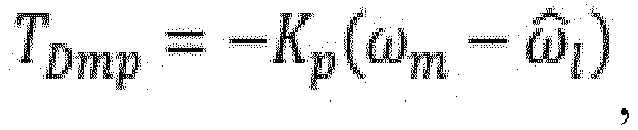
- T Dmp ⁇ K p ⁇ m ⁇ ⁇ ⁇ l , where Kp is a dimensionless control coefficient.
- an estimated angular velocity signal of the wheel based on the state observer is used, which is smoother due to being not affected by external factors, and has a short, especially a shorter delay than in the case of using a filter. Furthermore, this also makes it possible that the wheel angular velocity signal may be used throughout the process to extract juddering of the motor at a rotational speed, such that better extraction of juddering features can still be implemented at a zero crossing point of the motor torque.
- the compensated torque of the motor is calculated based on the actual angular velocity of the motor and the estimated angular velocity signal of the wheel that is calculated by means of the double closed-loop linear observer, such that the torque control system for a vehicle motor can be prevented from being affected by the system parameter changes and the working condition changes of the vehicle. Furthermore, the output signal from the state observer is delayed such that a relatively smooth compensated torque of the motor can be obtained, and the real-time performance of the compensated torque of the motor can thus be improved. According to an implementation of the disclosure, the estimated angular velocity of the motor is delayed in a targeted manner, such that a lag characteristic of signal transmission of the sensor in the electric vehicle can be simulated.
- the estimated angular velocity of the wheel is delayed in a targeted manner, such that a lag characteristic of signal transmission of the vehicle CAN bus can be simulated.
- a relevant delay processing module is provided such that a high update rate of the compensated torque of the motor can be achieved even in the case of using a wheel-relevant signal with a low sampling frequency.
- a torque control method for a vehicle motor which method is capable of being performed by the torque control system for a vehicle motor that has the above features and advantages.
- the method includes the following steps:
- the actual angular velocity ⁇ m of the motor is acquired from a motor sensor, and in the estimated value obtaining step, the estimated angular velocity ⁇ m of the motor is delayed to represent a delay time ⁇ t2 of transmission lag of the sensor, and the delayed estimated angular velocity ⁇ m of the motor is outputted at a first frequency, which steps may be performed by a second motor delay submodule of the torque control system for a vehicle motor.
- the actual angular velocity ⁇ l of the wheel is acquired from a vehicle CAN bus
- the estimated value obtaining step the estimated angular velocity ⁇ l of the wheel is delayed to represent a delay time ⁇ t1 of signal transmission lag of the CAN bus, and the delayed estimated angular velocity ⁇ l of the wheel is outputted at a second frequency for solving of the deviations, which steps may be performed by a second wheel delay submodule of the torque control system for a vehicle motor.
- the torque control method for a vehicle motor may have the advantages and characteristics described above in terms of the torque control system for a vehicle motor, and for the method, reference may be correspondingly made to the description of the system and FIG. 1 , which will not be repeated.
- a computer-readable storage medium having a computer program stored thereon, where when the computer program is executed by a processor, a torque control method for a vehicle motor of an electric vehicle according to one or more embodiments of the disclosure is implemented.
- the computer-readable storage medium mentioned herein includes various types of computer storage media, and may be any usable medium accessible to a general-purpose or special-purpose computer.
- the computer-readable storage medium may include a random access memory (RAM), a read-only memory (ROM), an erasable programmable read-only memory (EPROM), an electrically erasable programmable read-only memory (EEPROM), a register, a hard disk, a removable hard disk, a compact disc read-only memory (CD-ROM) or another optical disc memory, a magnetic disk memory or another magnetic storage device, or any other transitory or non-transitory media that can carry or store expected program code units having instruction or data structure forms and be accessible to the general-purpose or special-purpose computer or a general-purpose or special-purpose processor.
- RAM random access memory
- ROM read-only memory
- EPROM erasable programmable read-only memory
- EEPROM electrically erasable programmable read-only memory
- a register a hard disk, a removable hard disk, a compact disc read-only memory (CD-ROM) or another optical disc memory, a magnetic disk memory or another magnetic storage device, or any other transit
- a vehicle including the above torque control system for a vehicle motor and being capable of having the advantages and characteristics described above in terms of the torque control method or system for a vehicle motor, which will not be repeated.
Landscapes
- Engineering & Computer Science (AREA)
- Power Engineering (AREA)
- Transportation (AREA)
- Mechanical Engineering (AREA)
- Electric Propulsion And Braking For Vehicles (AREA)
- Control Of Electric Motors In General (AREA)
Abstract
Description
- The disclosure relates to the field of control technologies for motors of electric vehicles, and specifically to a torque control system for a vehicle motor, a torque control method for a vehicle motor that is capable of being implemented by the system, a computer-readable storage medium capable of performing the method, and a vehicle including such a system.
- A vehicle judders during running, especially during startup or braking (i.e., at a zero crossing point of a motor torque) of an electric vehicle, and a transmission system undergoes significant torsional vibrations, which makes the juddering more intense. Such a juddering phenomenon leads to shortened service life of or damage to related parts, and also worsens the problem of noise, thus bringing about a bad driving experience for users.
- At present, with regard to the juddering phenomenon, in most torque control methods for a vehicle motor, a filter or a wheel speed comparison method is used to extract juddering of the motor at a rotational speed and then a torque opposite to the juddering is applied to achieve an active damping effect. For example, in the case of using the filter, only limited juddering suppression may be implemented at a zero crossing point of the motor torque. This is mainly because the filter cannot effectively extract the juddering of the motor at a rotational speed that is caused by a gear clearance. It is known from the prior art that the wheel speed comparison method may be used in a targeted manner for such juddering suppression at the zero crossing point of the motor torque, that is, a target speed of the motor is solved based on a wheel speed signal. However, the wheel speed signal has the problems of a signal delay and a low update rate, thus failing to make good compensation for the motor torque. Furthermore, a directly obtained wheel speed signal is susceptible to interference from road conditions, thus enabling a compensated torque of the motor that is obtained based on the wheel speed signal to fluctuate with juddering at a wheel speed, which is certainly not undesirable.
- According to different aspects, an objective of the disclosure is to provide a torque control system for a vehicle motor that is capable of preventing juddering of the motor, a torque control method for a vehicle motor, a computer-readable storage medium, and a vehicle.
- In addition, the disclosure also aims to solve or alleviate other technical problems existing in the prior art.
- To solve the above problems, the disclosure provides a torque control system for a vehicle motor. Specifically, the system includes the following modules:
- a target torque obtaining unit configured to obtain a target torque TRef of the motor that is associated with a vehicle pedal parameter;
- a compensated torque calculation unit configured to calculate a compensated torque TDmp of the motor; and
- a theoretical torque calculation unit configured to calculate a theoretical torque TCmd of the motor based on the target torque TRef of the motor and the compensated torque of the motor,
- the compensated torque calculation unit including an angular velocity acquisition module, a first delay module, a state observer, a second delay module, a deviation solving module, and a compensated torque calculation module, where
- the angular velocity acquisition module is configured to obtain an actual angular velocity ωm of the motor that is sampled at a first frequency and an actual angular velocity ωl of a wheel that is sampled at a second frequency less than the first frequency and converted to a motor side;
- the first delay module is configured to delay the target torque TRef of the motor and transmit a delayed target torque Te of the motor to the state observer;
- the state observer is constructed as a double closed-loop linear observer and configured to obtain an estimated angular velocity ω̂m of the motor and an estimated angular velocity ω̂l of the wheel at the first frequency;
- the second delay module is configured to: delay the estimated angular velocity ω̂m of the motor and the estimated angular velocity ω̂l of the wheel that are outputted by the state observer to make same respectively synchronous with the acquired actual angular velocity ωm of the motor and the acquired actual angular velocity ωl of the wheel; and calculate a deviation between the estimated angular velocity ω̂m of the motor and the actual angular velocity ωm of the motor and a deviation between the estimated angular velocity ω̂l of the wheel and the actual angular velocity ωl of the wheel, where the deviations are fed back to the state observer; and
- the compensated torque calculation module is configured to calculate the compensated torque TDmp of the motor based on the received actual angular velocity ωm of the motor and the received estimated angular velocity ω̂l of the wheel.
- In the torque control system for a vehicle motor proposed according to a first aspect of the disclosure, the angular velocity acquisition module acquires the actual angular velocity ωl of the wheel by a vehicle controller area network (CAN) bus, and
correspondingly, the second delay module includes a second wheel delay submodule configured to delay the estimated angular velocity ω̂l of the wheel to represent a delay time △t 1 of signal transmission lag of the CAN bus and to transmit the estimated angular velocity ω̂l of the wheel to the deviation finding module at the second frequency. - In the torque control system for a vehicle motor proposed according to the first aspect of the disclosure, the angular velocity acquisition module acquires the actual angular velocity ωm of the motor from a motor sensor, and
correspondingly, the second delay module includes a second motor delay submodule configured to delay the estimated angular velocity ω̂m of the motor to represent a delay time △t 2 of transmission lag of the sensor and to transmit the estimated angular velocity ω̂m of the motor to the deviation solving module at the first frequency. - In the torque control system for a vehicle motor proposed according to the first aspect of the disclosure, a state-space equation for the state observer is constructed as:

- where x̂ is a real-time state variable matrix, and
- y is an actually measured output variable matrix, and

- ŷ is an output variable matrix, and

- C depends on a controlled quantity of the state observer;
- L is a feedback compensation matrix of 4 * 2 and is set depending on poles of a characteristic equation for the state observer;
- A, B, and u are system structural parameters, which are respectively as follows:

- where c is a damping coefficient of a transmission shaft of an electric vehicle, K is stiffness of the transmission shaft of the electric vehicle, Jm is a rotational inertia of the motor, Jl is a rotational inertia of the load, and Te is the delayed target torque of the motor.
- In the torque control system for a vehicle motor proposed according to the first aspect of the disclosure, the compensated torque calculation module is configured to calculate the compensated torque TDmp of the motor based on the following formula:
- According to a second aspect of the disclosure, there is also proposed a torque control method for a vehicle motor that is capable of being performed by such a system. The method includes the following steps:
- an obtaining step: obtaining a target torque TRef of the motor, an actual angular velocity ωm of the motor, and an actual angular velocity ωl of a wheel;
- a calculation step: calculating a compensated torque TDmp of the motor based on the target torque TRef of the motor, the actual angular velocity ωm of the motor, and the actual angular velocity ωl of the wheel; and
- a correction step: calculating a theoretical torque TCmd of the motor based on the target torque TRef of the motor and the compensated torque TDmp of the motor,
- where the calculation step includes the following steps:
- an estimated value obtaining step: calculating an estimated angular velocity ω̂m of the motor and an estimated angular velocity ω̂l of the wheel by means of a double closed-loop linear observer, where the estimated angular velocity ω̂m of the motor and the estimated angular velocity ω̂l of the wheel that are outputted by a state observer are delayed to make same respectively synchronous with the acquired actual angular velocity ωm of the motor and the acquired actual angular velocity ωl of the wheel, and calculating a deviation between the estimated angular velocity ω̂m of the motor and the actual angular velocity ωm of the motor and a deviation between the estimated angular velocity ω̂l of the wheel and the actual angular velocity ωl of the wheel, where the deviations are fed back to the state observer; and
- a compensated torque calculation step: calculating the compensated torque TDmp of the motor based on the acquired actual angular velocity ωm of the motor and the solved estimated angular velocity ω̂l of the wheel.
- In the torque control method for a vehicle motor proposed according to the second aspect of the disclosure, in the obtaining step, the actual angular velocity ωl of the wheel is acquired from a vehicle CAN bus, and
correspondingly, in the estimated value obtaining step, the estimated angular velocity ω̂l of the wheel is delayed to represent a delay time △t 1 of signal transmission lag of the CAN bus, and the delayed estimated angular velocity ω̂l of the wheel is outputted at a second frequency for solving of the deviations. - In the torque control method for a vehicle motor proposed according to the second aspect of the disclosure, in the obtaining step, the actual angular velocity ωm of the motor is acquired from a motor sensor, and
correspondingly, in the estimated value obtaining step, the estimated angular velocity ω̂m of the motor is delayed to represent a delay time △t2 of transmission lag of the sensor, and the delayed estimated angular velocity ω̂m of the motor is outputted at a first frequency for solving of the deviations. - According to a third aspect of the disclosure, there is also proposed a computer-readable storage medium having a computer program stored thereon, where when the computer program is executed by a processor, the above torque control method for a vehicle motor is implemented.
- Finally, according to a fourth aspect of the disclosure, there is also proposed a vehicle, the vehicle including the above torque control system for a vehicle motor and being capable of having the characteristics described above.
- The torque control system for a vehicle motor or the torque control method for a vehicle motor according to the disclosure cannot only improve the real-time performance of the compensated torque of the motor, but also can reduce or eliminate the impacts of factors such as system parameter changes and working condition changes.
- The above and other features of the disclosure will become apparent with reference to the accompany drawings, in which:
FIG. 1 is a partial flow block diagram of a torque control method for a vehicle motor according to the disclosure. - It can be readily understood that according to the technical solution of the disclosure, a person of ordinary skill in the art may propose multiple interchangeable structures and implementations without changing the essential spirit of the disclosure. Therefore, the following specific embodiments and the accompanying drawings are merely exemplary descriptions of the technical solutions of the disclosure, and should not be construed as the entirety of the disclosure or construed as limiting the technical solution of the disclosure.
- Orientation terms, such as up, down, left, right, front, rear, front side, back side, top, and bottom, which are or may be mentioned in this description, are defined with respect to the structures shown in the accompanying drawing, and are relative concepts, and therefore may correspondingly vary depending on different positions and different usage states. Therefore, these or other orientation terms should not be construed as restrictive terms as well. Moreover, the terms such as "first" "second", "third" or similar expressions are only used for description and distinction purposes, and should not be construed as indicating or implying the relative importance of corresponding members.
- Referring to
FIG. 1 , a torque control system for a vehicle motor according to the disclosure and a torque control method for a vehicle motor that is capable of being performed by the system are described in more detail, whereFIG. 1 shows an implementation of how to solve a compensated torque of a motor in a flow block diagram. Broadly speaking, the torque control system for a vehicle motor according to the disclosure includes a target torque obtaining unit, a compensated torque calculation unit, and a theoretical torque calculation unit. The target torque obtaining unit is configured to obtain or call a target torque TRef of the motor that is determined by an intent of a driver or a vehicle pedal parameter (such as an accelerator pedal depth parameter or a brake pedal depth parameter), or the target torque obtaining unit itself is capable of calculating the target torque TRef of the motor. The compensated torque calculation unit is configured to calculate a compensated torque TDmp of the motor according to vehicle-related parameters, where the compensated torque of the motor is related to juddering of the vehicle or juddering of the motor at a rotational speed. The theoretical torque calculation unit is configured to calculate a theoretical torque TCmd of the motor based on the target torque TRef of the motor and the compensated torque TDmp of the motor. The operation of the motor or a subsequent operating state of the motor is controlled through the theoretical torque of the motor. In the theoretical torque calculation unit, the theoretical torque TCmd of the motor can be obtained simply by summing the target torque TRef of the motor and the compensated torque TDmp of the motor. - Herein, the compensated torque calculation unit is configured to calculate the compensated torque TDmp of the motor based on an actual angular velocity ωm of the motor, an actual angular velocity ωl of the wheel, and the target torque TRef of the motor. It should be noted herein that the actual angular velocity ωl of the wheel is an angular velocity that has been converted to a motor side. For example, a rotational speed (which may be in revolutions per minute) measured by a wheel speed sensor is converted into an angular velocity of the wheel, and the wheel angular velocity is divided by a transmission ratio of a transmission system of the electric vehicle to obtain the above actual angular velocity of the wheel that is converted to the motor side. The term "actual angular velocity ωl of the wheel" or "estimated angular velocity ω̂l of the wheel" proposed herein represents the angular velocity that is converted to the motor side based on the transmission ratio of the transmission system of the vehicle. Herein, considering that the actual angular velocity ωl of the wheel is susceptible to system parameter changes and working condition changes of the vehicle, a double closed-loop linear observer for solving the estimated angular velocity ω̂l of the wheel based on which the compensated torque may be calculated is introduced herein. Specifically, the compensated torque calculation unit includes an angular velocity acquisition module, a first delay module, a state observer, a second delay module, a deviation solving module, and a compensated torque calculation module.
- The first delay module is configured to delay the target torque TRef of the motor, which depends on the intent of the driver, by △t3, and a delayed target torque Te of the motor is transmitted to the subsequent double closed-loop linear observer, where the delay operation is mainly used to simulate a delay effect achieved by a current loop, and the delay time △t3 depends on a pulse width modulation (PWM) switching frequency and parameter setting of the current loop. The time delay △t3 may be, for example, 1 ms.
- In addition, the angular velocity acquisition module is configured to acquire the actual angular velocity ωm of the motor at a first frequency and the actual angular velocity ωl of the wheel that is converted to the motor side at a second frequency, where the second frequency is less than the first frequency (as shown in
FIG. 1 , a sampling period for the first frequency is 1 ms, and a sampling period for the second frequency is 10 ms; in addition, for the sake of clarity, sampling periods are marked for the steps inFIG. 1 ). A difference between the two frequencies results from different data sources for the actual angular velocity of the motor and the actual angular velocity of the wheel, where the actual angular velocity of the motor may be generally called and initially processed from a motor sensor, while the actual angular velocity of the wheel generally needs to be transmitted by means of a vehicle CAN bus. Also considering the difference between the sampling frequencies and the common signal transmission lag, compared with common feedback regulation in the prior art, the disclosure provides for the second delay module between the state observer and the deviation solving module in a targeted manner, such that an estimated angular velocity ω̂m of the motor that is outputted by the state observer is kept synchronous with the acquired actual angular velocity ωm of the motor and the estimated angular velocity ω̂l of the wheel that is outputted by the state observer is kept synchronous with the acquired actual angular velocity ωl of the wheel. The double closed-loop linear observer makes calculations at the high first frequency. As shown in the figure, an estimated result is outputted per 1 ms, and the estimated angular velocity ω̂l of the wheel that is outputted every 1 ms is selected (for example, an output signal is selected every 10 ms) for subsequent calculations of a deviation between the estimated angular velocity of the wheel and the actual angular velocity ωl of the wheel. In addition, for a feedback signal circuit of the state observer, it should be noted that where the deviation (ωl - ω̂l ) between the actual angular velocity ωl of the wheel and the estimated angular velocity ω̂l of the wheel is fed back to the state observer every 10 ms, the state observer makes calculations based on the fed-back deviation within the time interval of 10 ms. Unlike this, when making calculations every 1 ms, the state observer makes calculations based on a deviation (ωm - ω̂m ) between the actual angular velocity ωm of the motor and the estimated angular velocity ω̂m of the motor that is fed back every 1 ms. By delaying a signal for an actual angular velocity signal of the wheel that has a relatively long sampling period and changing a sampling frequency of the signal in a targeted manner, an update rate of motor torque control or compensated torque calculation (which can achieve an active damping control effect of preventing juddering) based on a wheel speed signal can be increased, for example, the update rate is increased from 10 ms in the past to 1 ms. - In an optional implementation, if the angular velocity acquisition module acquires the actual angular velocity ωl of the wheel from the vehicle CAN bus, the second delay module is designed in such a way that the second delay module includes a second wheel delay submodule configured to delay the estimated angular velocity ω̂l of the wheel to represent a delay time △t1 of signal transmission lag of the CAN bus and to transmit the estimated angular velocity ω̂l of the wheel to the downstream deviation solving module at the second frequency. Herein, the delay time △t1 depends on a communication period of the vehicle CAN bus, and may be set to several milliseconds, for example.
- In another optional implementation, if the angular velocity acquisition module acquires the actual angular velocity ωm of the motor from the motor sensor, the second delay module is designed in such a way that the second delay module includes a second motor delay submodule configured to delay the estimated angular velocity ω̂m of the motor to represent a delay time △t2 of transmission lag of the sensor and to transmit the estimated angular velocity ω̂m of the motor to the downstream deviation solving module at the first frequency. Herein, the delay time △t2 depends on a sensor signal analysis process for the actual angular velocity ωm of the motor and a filtering process of related hardware, and may be set to several milliseconds, for example.
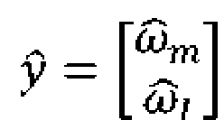
- Next, the state observer in the form of the double closed-loop linear observer is described in detail. A state-space equation for the state observer is constructed as:

- where x̂ is a real-time state variable matrix, and

- y is an actually measured output variable matrix, and

- ŷ is an output variable matrix, and
- C depends on a controlled quantity of the state observer;
- A, B, and u are system structural parameters, which are respectively as follows:

- where c is a damping coefficient of a transmission shaft of an electric vehicle, K is stiffness of the transmission shaft of the electric vehicle, Jm is a rotational inertia of the motor, Jl is a rotational inertia of the load, and Te is the delayed target torque of the motor; and L is a feedback compensation matrix of 4 * 2,

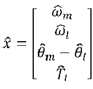
- Based on the above state-space equation, the estimated angular velocity ω̂m of the motor, the estimated angular velocity ω̂l of the wheel, an angle difference (θ̂m - θ̂l ), and the estimated torque T̂l of the load may be obtained, which are respectively as follows:


- In an optional implementation, the compensated torque TDmp of the motor that is used to correct the target torque TRef of the motor is calculated based on the actual angular velocity ωm of the motor and the estimated angular velocity ω̂l of the wheel that is obtained by the double closed-loop linear observer, and the target torque TRef of the motor and the compensated torque TDmp of the motor are summed to obtain the theoretical torque TCmd of the motor. Specifically, as shown in a lower half part of
FIG. 1 , calculations are made according to the following formula:
- In summary, the compensated torque of the motor is calculated based on the actual angular velocity of the motor and the estimated angular velocity signal of the wheel that is calculated by means of the double closed-loop linear observer, such that the torque control system for a vehicle motor can be prevented from being affected by the system parameter changes and the working condition changes of the vehicle. Furthermore, the output signal from the state observer is delayed such that a relatively smooth compensated torque of the motor can be obtained, and the real-time performance of the compensated torque of the motor can thus be improved. According to an implementation of the disclosure, the estimated angular velocity of the motor is delayed in a targeted manner, such that a lag characteristic of signal transmission of the sensor in the electric vehicle can be simulated. According to another implementation of the disclosure, the estimated angular velocity of the wheel is delayed in a targeted manner, such that a lag characteristic of signal transmission of the vehicle CAN bus can be simulated. According to another implementation of the disclosure, a relevant delay processing module is provided such that a high update rate of the compensated torque of the motor can be achieved even in the case of using a wheel-relevant signal with a low sampling frequency.
- According to a second aspect of the disclosure, there is also proposed a torque control method for a vehicle motor, which method is capable of being performed by the torque control system for a vehicle motor that has the above features and advantages. The method includes the following steps:
- an obtaining step: obtaining a target torque TRef of the motor, an actual angular velocity ωm of the motor, and an actual angular velocity ωl of a wheel, which step may be performed by a target torque obtaining unit and a rotating acquisition module of a compensated torque calculation unit of the torque control system for a vehicle motor;
- a calculation step: calculating a compensated torque TDmp of the motor based on the target torque TRef of the motor, the actual angular velocity ωm of the motor, and the actual angular velocity ωl of the wheel, which step may be performed, on the whole, by the compensated torque calculation unit of the torque control system for a vehicle motor; and
- a correction step: calculating a theoretical torque TCmd of the motor based on the target torque TRef of the motor and the compensated torque TDmp of the motor, which step may be performed by a theoretical torque calculation unit of the torque control system for a vehicle motor,
- where the calculation step includes the following steps:
- an estimated value obtaining step: calculating an estimated angular velocity ω̂m of the motor and an estimated angular velocity ω̂l of the wheel by means of a double closed-loop linear observer, where the estimated angular velocity ω̂m of the motor and the estimated angular velocity ω̂l of the wheel that are outputted by a state observer are delayed to make same respectively synchronous with the acquired actual angular velocity ωm of the motor and the acquired actual angular velocity ωl of the wheel (which may be performed by a second delay module of the torque control system for a vehicle motor), and calculating a deviation between the estimated angular velocity ω̂m of the motor and the actual angular velocity ωm of the motor and a deviation between the estimated angular velocity ω̂l of the wheel and the actual angular velocity ωl of the wheel (which may be performed by a deviation finding module), where the deviations are fed back to the state observer; and
- a compensated torque calculation step: calculating the compensated torque TDmp of the motor based on the acquired actual angular velocity ωm of the motor and the solved estimated angular velocity ω̂l of the wheel, which step may be performed by a compensated torque calculation module of the torque control system for a vehicle motor.
- In an optional implementation, in the obtaining step, the actual angular velocity ωm of the motor is acquired from a motor sensor, and in the estimated value obtaining step, the estimated angular velocity ω̂m of the motor is delayed to represent a delay time △t2 of transmission lag of the sensor, and the delayed estimated angular velocity ω̂m of the motor is outputted at a first frequency, which steps may be performed by a second motor delay submodule of the torque control system for a vehicle motor.
- In another optional implementation, in the obtaining step, the actual angular velocity ωl of the wheel is acquired from a vehicle CAN bus, and in the estimated value obtaining step, the estimated angular velocity ω̂l of the wheel is delayed to represent a delay time △t1 of signal transmission lag of the CAN bus, and the delayed estimated angular velocity ω̂l of the wheel is outputted at a second frequency for solving of the deviations, which steps may be performed by a second wheel delay submodule of the torque control system for a vehicle motor.
- It should be noted herein that the torque control method for a vehicle motor according to the disclosure may have the advantages and characteristics described above in terms of the torque control system for a vehicle motor, and for the method, reference may be correspondingly made to the description of the system and
FIG. 1 , which will not be repeated. - According to a third aspect of the disclosure, there is also proposed a computer-readable storage medium having a computer program stored thereon, where when the computer program is executed by a processor, a torque control method for a vehicle motor of an electric vehicle according to one or more embodiments of the disclosure is implemented. The computer-readable storage medium mentioned herein includes various types of computer storage media, and may be any usable medium accessible to a general-purpose or special-purpose computer. For example, the computer-readable storage medium may include a random access memory (RAM), a read-only memory (ROM), an erasable programmable read-only memory (EPROM), an electrically erasable programmable read-only memory (EEPROM), a register, a hard disk, a removable hard disk, a compact disc read-only memory (CD-ROM) or another optical disc memory, a magnetic disk memory or another magnetic storage device, or any other transitory or non-transitory media that can carry or store expected program code units having instruction or data structure forms and be accessible to the general-purpose or special-purpose computer or a general-purpose or special-purpose processor. For the computer-readable storage medium according to the disclosure, reference may be made to the explanations of the torque control method or system for a vehicle motor according to the disclosure, which will not be repeated.
- According to a fourth aspect of the disclosure, there is also proposed a vehicle, the vehicle including the above torque control system for a vehicle motor and being capable of having the advantages and characteristics described above in terms of the torque control method or system for a vehicle motor, which will not be repeated.
- It should be understood that all of the above preferred embodiments are exemplary rather than limiting, and any modification or variation made by those skilled in the art to the specific embodiments described above without departing from the concept of the disclosure shall fall within the scope of legal protection of the disclosure.
Claims (10)
- A torque control system for a vehicle motor, comprising the following modules:a target torque obtaining unit configured to obtain a target torque TRef of the motor that is associated with a vehicle pedal parameter;a compensated torque calculation unit configured to calculate a compensated torque TDmp of the motor; anda theoretical torque calculation unit configured to calculate a theoretical torque TCmd of the motor based on the target torque TRef of the motor and the compensated torque TDmp of the motor,the compensated torque calculation unit comprising an angular velocity acquisition module, a first delay module, a state observer, a second delay module, a deviation solving module, and a compensated torque calculation module, whereinthe angular velocity acquisition module is configured to obtain an actual angular velocity ωm of the motor that is sampled at a first frequency and an actual angular velocity ωl of a wheel that is sampled at a second frequency less than the first frequency and converted to a motor side;the first delay module is configured to delay the target torque TRef of the motor and transmit a delayed target torque Te of the motor to the state observer;the state observer is constructed as a double closed-loop linear observer and configured to obtain an estimated angular velocity ω̂m of the motor and an estimated angular velocity ω̂l of the wheel at the first frequency;the second delay module is configured to: delay the estimated angular velocity ω̂m of the motor and the estimated angular velocity ω̂l of the wheel that are outputted by the state observer to make same respectively synchronous with the acquired actual angular velocity ωm of the motor and the acquired actual angular velocity ωl of the wheel; and calculate a deviation between the estimated angular velocity ω̂m of the motor and the actual angular velocity ωm of the motor and a deviation between the estimated angular velocity ω̂l of the wheel and the actual angular velocity ωl of the wheel, wherein the deviations are fed back to the state observer; andthe compensated torque calculation module is configured to calculate the compensated torque TDmp of the motor based on the received actual angular velocity ωm of the motor and the received estimated angular velocity ω̂l of the wheel.
- The torque control system for a vehicle motor according to claim 1, wherein the angular velocity acquisition module acquires the actual angular velocity ω / of the wheel by a vehicle controller area network (CAN) bus, and
correspondingly, the second delay module comprises a second wheel delay submodule configured to delay the estimated angular velocity ω̂l of the wheel to represent a delay time △t1 of signal transmission lag of the CAN bus and to transmit the estimated angular velocity ω̂l of the wheel to the deviation finding module at the second frequency. - The torque control system for a vehicle motor according to claim 1, wherein the angular velocity acquisition module acquires the actual angular velocity ωm of the motor from a motor sensor, and
correspondingly, the second delay module comprises a second motor delay submodule configured to delay the estimated angular velocity ω̂m of the motor to represent a delay time △t 2 of transmission lag of the sensor and to transmit the estimated angular velocity ω̂m of the motor to the deviation solving module at the first frequency. - The torque control system for a vehicle motor according to claim 1, wherein a state-space equation for the state observer is constructed as:
 wherein x̂ is a real-time state variable matrix, and
 y is an actually measured output variable matrix, and
 ŷ is an output variable matrix, and
 C depends on a controlled quantity of the state observer;L is a feedback compensation matrix of 4 * 2 and is set depending on poles of a characteristic equation for the state observer;A, B, and u are system structural parameters, which are respectively as follows:
 wherein c is a damping coefficient of a transmission shaft of an electric vehicle, K is stiffness of the transmission shaft of the electric vehicle, Jm is a rotational inertia of the motor, Jl is a rotational inertia of the load, and Te is the delayed target torque of the motor.
 - The torque control system for a vehicle motor according to any one of claims 1 to 4, wherein the compensated torque calculation module is configured to calculate the compensated torque TDmp of the motor based on the following formula:

- A torque control method for a vehicle motor, which method is capable of being performed by a torque control system for a vehicle motor according to any one of claims 1 to 5, the method comprising the following steps:an obtaining step: obtaining a target torque TRef of the motor, an actual angular velocity ωm of the motor, and an actual angular velocity ωl of a wheel;a calculation step: calculating a compensated torque TDmp of the motor based on the target torque TRef of the motor, the actual angular velocity ωm of the motor, and the actual angular velocity ωl of the wheel; anda correction step: calculating a theoretical torque TCmd of the motor based on the target torque TRef of the motor and the compensated torque TDmp of the motor,wherein the calculation step comprises the following steps:an estimated value obtaining step: calculating an estimated angular velocity ω̂m of the motor and an estimated angular velocity ω̂l of the wheel by means of a double closed-loop linear observer, wherein the estimated angular velocity ω̂m of the motor and the estimated angular velocity ω̂l of the wheel that are outputted by a state observer are delayed to make same respectively synchronous with the acquired actual angular velocity ωm of the motor and the acquired actual angular velocity ωl of the wheel, and calculating a deviation between the estimated angular velocity ω̂m of the motor and the actual angular velocity ωm of the motor and a deviation between the estimated angular velocity ω̂l of the wheel and the actual angular velocity ωl of the wheel, wherein the deviations are fed back to the state observer; anda compensated torque calculation step: calculating the compensated torque TDmp of the motor based on the acquired actual angular velocity ωm of the motor and the solved estimated angular velocity ω̂l of the wheel.
- The torque control method for a vehicle motor according to claim 6, wherein in the obtaining step, the actual angular velocity ωl of the wheel is acquired from a vehicle CAN bus, and
correspondingly, in the estimated value obtaining step, the estimated angular velocity ω̂l of the wheel is delayed to represent a delay time △t 1 of signal transmission lag of the CAN bus, and the delayed estimated angular velocity ω̂l of the wheel is outputted at a second frequency for solving of the deviations. - The torque control method for a vehicle motor according to claim 7, wherein in the obtaining step, the actual angular velocity ωm of the motor is acquired from a motor sensor, and
correspondingly, in the estimated value obtaining step, the estimated angular velocity ω̂m of the motor is delayed to represent a delay time △t 2 of transmission lag of the sensor, and the delayed estimated angular velocity ω̂m of the motor is outputted at a first frequency for solving of the deviations. - A computer-readable storage medium having a computer program stored thereon, wherein when the computer program is executed by a processor, a torque control method for a vehicle motor according to any one of claims 6 to 8 is implemented.
- A vehicle, comprising a torque control system for a vehicle motor according to any one of claims 1 to 5.
Applications Claiming Priority (1)
| Application Number | Priority Date | Filing Date | Title |
|---|---|---|---|
| CN202310796735.9A CN119217996B (en) | 2023-06-29 | 2023-06-29 | Vehicle motor torque control system, control method, medium and vehicle |
Publications (3)
| Publication Number | Publication Date |
|---|---|
| EP4333292A2 true EP4333292A2 (en) | 2024-03-06 |
| EP4333292A3 EP4333292A3 (en) | 2024-07-24 |
| EP4333292B1 EP4333292B1 (en) | 2026-02-04 |
Family
ID=89430501
Family Applications (1)
| Application Number | Title | Priority Date | Filing Date |
|---|---|---|---|
| EP23219496.9A Active EP4333292B1 (en) | 2023-06-29 | 2023-12-21 | Torque control system and method for vehicle motor, medium, and vehicle |
Country Status (2)
| Country | Link |
|---|---|
| EP (1) | EP4333292B1 (en) |
| CN (1) | CN119217996B (en) |
Cited By (1)
| Publication number | Priority date | Publication date | Assignee | Title |
|---|---|---|---|---|
| CN119840438A (en) * | 2025-01-07 | 2025-04-18 | 一汽解放汽车有限公司 | Driving motor rotating speed control system, design method thereof and new energy vehicle |
Family Cites Families (12)
| Publication number | Priority date | Publication date | Assignee | Title |
|---|---|---|---|---|
| JP5411687B2 (en) * | 2009-12-28 | 2014-02-12 | 川崎重工業株式会社 | Robot control device |
| JP5861554B2 (en) * | 2012-04-18 | 2016-02-16 | 日産自動車株式会社 | Vibration suppression control device for vehicle |
| US9809213B2 (en) * | 2014-01-14 | 2017-11-07 | Ford Global Technologies, Llc | Power split hybrid electric vehicle motor torque control using state estimation |
| JP6578584B2 (en) * | 2015-08-25 | 2019-09-25 | 日立オートモティブシステムズ株式会社 | Control device for electric vehicle |
| KR20170080420A (en) * | 2015-12-31 | 2017-07-10 | 이래오토모티브시스템 주식회사 | Control apparatus and method for electric power steering |
| CN109941120B (en) * | 2019-03-15 | 2021-09-17 | 南京航空航天大学 | System and control algorithm for active vibration control of electric vehicle |
| CN111976824B (en) * | 2019-05-21 | 2021-11-16 | 上海汽车集团股份有限公司 | Inertia compensation method and related device of electric power steering system |
| JP6977849B1 (en) * | 2020-09-30 | 2021-12-08 | 株式会社明電舎 | Vibration suppression control device and vibration suppression control method for vehicle system |
| CN114954030B (en) * | 2021-08-30 | 2025-01-28 | 长城汽车股份有限公司 | Torque control method and related device of electric vehicle |
| CN116252804A (en) * | 2021-12-09 | 2023-06-13 | 北京罗克维尔斯科技有限公司 | Vehicle control method, device, vehicle controller and medium |
| CN113997927B (en) * | 2021-12-15 | 2023-10-27 | 吉林大学 | A stability control method based on distributed drive electric vehicles |
| CN116198327B (en) * | 2023-03-20 | 2025-12-16 | 一汽解放汽车有限公司 | Method, device, equipment and medium for observing rotation speed of equivalent motor |
-
2023
- 2023-06-29 CN CN202310796735.9A patent/CN119217996B/en active Active
- 2023-12-21 EP EP23219496.9A patent/EP4333292B1/en active Active
Cited By (1)
| Publication number | Priority date | Publication date | Assignee | Title |
|---|---|---|---|---|
| CN119840438A (en) * | 2025-01-07 | 2025-04-18 | 一汽解放汽车有限公司 | Driving motor rotating speed control system, design method thereof and new energy vehicle |
Also Published As
| Publication number | Publication date |
|---|---|
| EP4333292B1 (en) | 2026-02-04 |
| EP4333292A3 (en) | 2024-07-24 |
| CN119217996B (en) | 2025-09-30 |
| CN119217996A (en) | 2024-12-31 |
Similar Documents
| Publication | Publication Date | Title |
|---|---|---|
| CN113602101B (en) | A control method, device and vehicle for suppressing motor jitter | |
| US9018870B2 (en) | Control device | |
| CN112009268B (en) | Vehicle shaking control method and device, driving control system and vehicle | |
| EP1968184A2 (en) | Motor controller and motor control system | |
| US9440636B2 (en) | Vibration damping control apparatus | |
| EP4333292B1 (en) | Torque control system and method for vehicle motor, medium, and vehicle | |
| CN115102461B (en) | Method, processor, system and electric vehicle for suppressing vibration of electric vehicle | |
| US11394326B2 (en) | Control method and control device for electric vehicle | |
| EP3787181B1 (en) | Controller, motor drive device and electric vehicle system | |
| WO2022105367A1 (en) | Gear adjustment method and apparatus for autonomous vehicle | |
| EP3309377B1 (en) | System and method for controlling engine operation | |
| EP3186882B1 (en) | Variable magnetization machine controller | |
| JP2015105043A (en) | Vehicle vibration control device for vehicle | |
| CN115366696B (en) | Method and device for suppressing jitter of electric automobile, electric automobile and storage medium | |
| CN117048362A (en) | New energy vehicle vehicle torque zero-crossing control method, system, server and media | |
| EP3044868B1 (en) | Variable magnetization machine controller | |
| JP5470821B2 (en) | Vehicle driving force control device | |
| JP3796959B2 (en) | Vehicle speed control device for vehicles with continuously variable transmission | |
| CN117261613B (en) | A torque control method, device, equipment and vehicle | |
| US20210061249A1 (en) | Real-time optimization control method for electro-mechanical transmission system | |
| JP2013055756A (en) | Motor control device for vehicle | |
| EP4492673A1 (en) | Motor control device, and automatic adjustment method for same | |
| CN117261614B (en) | Torque control method, torque control device, torque control equipment and vehicle | |
| KR101704220B1 (en) | Method for controlling engine full load mode entry of hybrid electric vehicle | |
| US7005826B2 (en) | Method for enhancing the control response of a drive train having backlash and/or elasticity of a machine tool or production machine |
Legal Events
| Date | Code | Title | Description |
|---|---|---|---|
| PUAI | Public reference made under article 153(3) epc to a published international application that has entered the european phase |
Free format text: ORIGINAL CODE: 0009012 |
|
| STAA | Information on the status of an ep patent application or granted ep patent |
Free format text: STATUS: REQUEST FOR EXAMINATION WAS MADE |
|
| 17P | Request for examination filed |
Effective date: 20231221 |
|
| AK | Designated contracting states |
Kind code of ref document: A2 Designated state(s): AL AT BE BG CH CY CZ DE DK EE ES FI FR GB GR HR HU IE IS IT LI LT LU LV MC ME MK MT NL NO PL PT RO RS SE SI SK SM TR |
|
| PUAL | Search report despatched |
Free format text: ORIGINAL CODE: 0009013 |
|
| AK | Designated contracting states |
Kind code of ref document: A3 Designated state(s): AL AT BE BG CH CY CZ DE DK EE ES FI FR GB GR HR HU IE IS IT LI LT LU LV MC ME MK MT NL NO PL PT RO RS SE SI SK SM TR |
|
| RIC1 | Information provided on ipc code assigned before grant |
Ipc: F16H 57/00 20120101ALI20240619BHEP Ipc: H02P 21/05 20060101ALI20240619BHEP Ipc: B60L 15/20 20060101ALI20240619BHEP Ipc: H02P 21/13 20060101AFI20240619BHEP |
|
| STAA | Information on the status of an ep patent application or granted ep patent |
Free format text: STATUS: EXAMINATION IS IN PROGRESS |
|
| 17Q | First examination report despatched |
Effective date: 20250227 |
|
| GRAP | Despatch of communication of intention to grant a patent |
Free format text: ORIGINAL CODE: EPIDOSNIGR1 |
|
| STAA | Information on the status of an ep patent application or granted ep patent |
Free format text: STATUS: GRANT OF PATENT IS INTENDED |
|
| INTG | Intention to grant announced |
Effective date: 20250904 |
|
| GRAS | Grant fee paid |
Free format text: ORIGINAL CODE: EPIDOSNIGR3 |
|
| GRAA | (expected) grant |
Free format text: ORIGINAL CODE: 0009210 |
|
| STAA | Information on the status of an ep patent application or granted ep patent |
Free format text: STATUS: THE PATENT HAS BEEN GRANTED |
|
| AK | Designated contracting states |
Kind code of ref document: B1 Designated state(s): AL AT BE BG CH CY CZ DE DK EE ES FI FR GB GR HR HU IE IS IT LI LT LU LV MC ME MK MT NL NO PL PT RO RS SE SI SK SM TR |
|
| REG | Reference to a national code |
Ref country code: CH Ref legal event code: F10 Free format text: ST27 STATUS EVENT CODE: U-0-0-F10-F00 (AS PROVIDED BY THE NATIONAL OFFICE) Effective date: 20260204 Ref country code: GB Ref legal event code: FG4D |
|
| REG | Reference to a national code |
Ref country code: IE Ref legal event code: FG4D |
|
| REG | Reference to a national code |
Ref country code: DE Ref legal event code: R096 Ref document number: 602023011596 Country of ref document: DE |