EP4333240A1 - Power distribution device and transportation device having power distribution device - Google Patents
Power distribution device and transportation device having power distribution device Download PDFInfo
- Publication number
- EP4333240A1 EP4333240A1 EP22851764.5A EP22851764A EP4333240A1 EP 4333240 A1 EP4333240 A1 EP 4333240A1 EP 22851764 A EP22851764 A EP 22851764A EP 4333240 A1 EP4333240 A1 EP 4333240A1
- Authority
- EP
- European Patent Office
- Prior art keywords
- precharging
- power distribution
- distribution device
- fuse
- resistor
- Prior art date
- Legal status (The legal status is an assumption and is not a legal conclusion. Google has not performed a legal analysis and makes no representation as to the accuracy of the status listed.)
- Pending
Links
Images


Classifications
-
- H—ELECTRICITY
- H02—GENERATION; CONVERSION OR DISTRIBUTION OF ELECTRIC POWER
- H02B—BOARDS, SUBSTATIONS OR SWITCHING ARRANGEMENTS FOR THE SUPPLY OR DISTRIBUTION OF ELECTRIC POWER
- H02B1/00—Frameworks, boards, panels, desks, casings; Details of substations or switching arrangements
- H02B1/18—Disposition or arrangement of fuses
-
- B—PERFORMING OPERATIONS; TRANSPORTING
- B60—VEHICLES IN GENERAL
- B60L—PROPULSION OF ELECTRICALLY-PROPELLED VEHICLES; SUPPLYING ELECTRIC POWER FOR AUXILIARY EQUIPMENT OF ELECTRICALLY-PROPELLED VEHICLES; ELECTRODYNAMIC BRAKE SYSTEMS FOR VEHICLES IN GENERAL; MAGNETIC SUSPENSION OR LEVITATION FOR VEHICLES; MONITORING OPERATING VARIABLES OF ELECTRICALLY-PROPELLED VEHICLES; ELECTRIC SAFETY DEVICES FOR ELECTRICALLY-PROPELLED VEHICLES
- B60L1/00—Supplying electric power to auxiliary equipment of vehicles
-
- H—ELECTRICITY
- H02—GENERATION; CONVERSION OR DISTRIBUTION OF ELECTRIC POWER
- H02J—ELECTRIC POWER NETWORKS; CIRCUIT ARRANGEMENTS OR SYSTEMS FOR SUPPLYING OR DISTRIBUTING ELECTRIC POWER; SYSTEMS FOR STORING ELECTRIC ENERGY
- H02J7/00—Circuit arrangements for charging or discharging batteries or for supplying loads from batteries
- H02J7/60—Circuit arrangements for charging or discharging batteries or for supplying loads from batteries including safety or protection arrangements
- H02J7/663—Circuit arrangements for charging or discharging batteries or for supplying loads from batteries including safety or protection arrangements using battery or load disconnect circuits
-
- B—PERFORMING OPERATIONS; TRANSPORTING
- B60—VEHICLES IN GENERAL
- B60K—ARRANGEMENT OR MOUNTING OF PROPULSION UNITS OR OF TRANSMISSIONS IN VEHICLES; ARRANGEMENT OR MOUNTING OF PLURAL DIVERSE PRIME-MOVERS IN VEHICLES; AUXILIARY DRIVES FOR VEHICLES; INSTRUMENTATION OR DASHBOARDS FOR VEHICLES; ARRANGEMENTS IN CONNECTION WITH COOLING, AIR INTAKE, GAS EXHAUST OR FUEL SUPPLY OF PROPULSION UNITS IN VEHICLES
- B60K1/00—Arrangement or mounting of electrical propulsion units
- B60K1/04—Arrangement or mounting of electrical propulsion units of the electric storage means for propulsion
-
- H—ELECTRICITY
- H01—ELECTRIC ELEMENTS
- H01H—ELECTRIC SWITCHES; RELAYS; SELECTORS; EMERGENCY PROTECTIVE DEVICES
- H01H85/00—Protective devices in which the current flows through a part of fusible material and this current is interrupted by displacement of the fusible material when this current becomes excessive
- H01H85/02—Details
- H01H85/0241—Structural association of a fuse and another component or apparatus
-
- H—ELECTRICITY
- H02—GENERATION; CONVERSION OR DISTRIBUTION OF ELECTRIC POWER
- H02B—BOARDS, SUBSTATIONS OR SWITCHING ARRANGEMENTS FOR THE SUPPLY OR DISTRIBUTION OF ELECTRIC POWER
- H02B1/00—Frameworks, boards, panels, desks, casings; Details of substations or switching arrangements
- H02B1/20—Bus-bar or other wiring layouts, e.g. in cubicles, in switchyards
-
- H—ELECTRICITY
- H02—GENERATION; CONVERSION OR DISTRIBUTION OF ELECTRIC POWER
- H02B—BOARDS, SUBSTATIONS OR SWITCHING ARRANGEMENTS FOR THE SUPPLY OR DISTRIBUTION OF ELECTRIC POWER
- H02B1/00—Frameworks, boards, panels, desks, casings; Details of substations or switching arrangements
- H02B1/26—Casings; Parts thereof or accessories therefor
-
- H—ELECTRICITY
- H02—GENERATION; CONVERSION OR DISTRIBUTION OF ELECTRIC POWER
- H02B—BOARDS, SUBSTATIONS OR SWITCHING ARRANGEMENTS FOR THE SUPPLY OR DISTRIBUTION OF ELECTRIC POWER
- H02B1/00—Frameworks, boards, panels, desks, casings; Details of substations or switching arrangements
- H02B1/26—Casings; Parts thereof or accessories therefor
- H02B1/46—Boxes; Parts thereof or accessories therefor
- H02B1/48—Mounting of devices therein
-
- H—ELECTRICITY
- H02—GENERATION; CONVERSION OR DISTRIBUTION OF ELECTRIC POWER
- H02J—ELECTRIC POWER NETWORKS; CIRCUIT ARRANGEMENTS OR SYSTEMS FOR SUPPLYING OR DISTRIBUTING ELECTRIC POWER; SYSTEMS FOR STORING ELECTRIC ENERGY
- H02J7/00—Circuit arrangements for charging or discharging batteries or for supplying loads from batteries
- H02J7/34—Parallel operation in networks using both storage and other DC sources, e.g. providing buffering
- H02J7/345—Parallel operation in networks using both storage and other DC sources, e.g. providing buffering using capacitors as storage or buffering devices
-
- B—PERFORMING OPERATIONS; TRANSPORTING
- B60—VEHICLES IN GENERAL
- B60L—PROPULSION OF ELECTRICALLY-PROPELLED VEHICLES; SUPPLYING ELECTRIC POWER FOR AUXILIARY EQUIPMENT OF ELECTRICALLY-PROPELLED VEHICLES; ELECTRODYNAMIC BRAKE SYSTEMS FOR VEHICLES IN GENERAL; MAGNETIC SUSPENSION OR LEVITATION FOR VEHICLES; MONITORING OPERATING VARIABLES OF ELECTRICALLY-PROPELLED VEHICLES; ELECTRIC SAFETY DEVICES FOR ELECTRICALLY-PROPELLED VEHICLES
- B60L2270/00—Problem solutions or means not otherwise provided for
- B60L2270/20—Inrush current reduction, i.e. avoiding high currents when connecting the battery
-
- H—ELECTRICITY
- H02—GENERATION; CONVERSION OR DISTRIBUTION OF ELECTRIC POWER
- H02J—ELECTRIC POWER NETWORKS; CIRCUIT ARRANGEMENTS OR SYSTEMS FOR SUPPLYING OR DISTRIBUTING ELECTRIC POWER; SYSTEMS FOR STORING ELECTRIC ENERGY
- H02J2207/00—Details of circuit arrangements for charging or discharging batteries or supplying loads from batteries
- H02J2207/50—Charging of capacitors, supercapacitors, ultra-capacitors or double layer capacitors
Definitions
- the present disclosure relates to the field of power distribution device technologies and transportation device technologies, and more specifically, to a power distribution device and a transportation device having the power distribution device.
- a power distribution device is mainly composed of a main relay, a precharging relay, an aluminum shell resistor, and a resistance wire which are tied and fixed by using cable ties and snaps.
- the power distribution device composed in the above way is simple to operate and convenient to maintain, as a modular product, the power distribution device has insufficient product attributes of parts.
- the product integration is low, and the overall dimension structure is rather large. The main reason is that components in the module are still independent individuals, and are only spliced together by simple methods such as bolts and snaps, and the wiring harness is fixed by cable ties. Therefore, the product integration is low.
- the present disclosure is intended to solve at least one of the above technical problems, and provides a power distribution device and a transportation device having the power distribution device, which leads to a high internal space utilization rate and a relatively low cost.
- an embodiment of the present disclosure provides a power distribution device.
- the power distribution device includes a housing, a precharging circuit module, and a main positive circuit module.
- the housing has a mounting cavity.
- the precharging circuit module is configured to precharge a capacitor element in an electrical appliance, and includes a precharging relay.
- the precharging relay is connected with the housing.
- the main positive circuit module is configured to be closed after the precharging circuit module is opened, and the main positive circuit module and the precharging circuit module are stacked in the mounting cavity in an up-down direction.
- the main positive circuit module includes a fuse and a main relay core.
- the main relay core is connected with the housing.
- the power distribution device has an input terminal and a first output terminal.
- a first end of the fuse is the input terminal or connected with the input terminal, and a second end of the fuse is connected with a first end of the main relay core.
- a second end of the main relay core is the first output terminal or connected with the first output terminal.
- a first end of the precharging circuit module is connected with the input terminal or the second end of the fuse, and a second end of the precharging circuit module is connected with the second end of the main relay core or the first output terminal.
- the precharging circuit module further includes a precharging resistor.
- the precharging relay and the main relay core are respectively seated to two ends of the mounting cavity, the fuse and the precharging resistor are arranged between the precharging relay and the main relay core, the precharging resistor is seated to a bottom of the mounting cavity, and the fuse is located above the precharging resistor.
- the fuse and the precharging resistor are close to the precharging relay and the main relay core.
- the precharging relay is connected with the housing through a clamping structure or a potting structure
- the main relay core is connected with the housing through a potting structure or a clamping structure.
- the housing includes a bottom shell and a surface cover.
- the surface cover is connected with the bottom shell through a snap-fit structure or a locking member to form the mounting cavity
- the precharging relay is connected with the bottom shell through the clamping structure
- the main relay core is connected with the bottom shell through the potting structure.
- the surface cover is provided with a first mounting hole corresponding to an upper part of the precharging relay, and the surface cover is provided with a second mounting hole and a third mounting hole corresponding to an upper part of the main relay core.
- the surface cover is provided with a mounting window for the fuse to be placed, and the precharging relay is located below the first mounting hole.
- the first end of the fuse extends to a position above the first mounting hole, and the second end of the fuse extends to a position above the second mounting hole.
- the first end of the main relay core is located below the second mounting hole, the second end of the main relay core is located below the third mounting hole, and the second end of the fuse is connected with the first end of the main relay core through a first locking member passing through the second mounting hole.
- the potting structure is formed through solidification of potting adhesive.
- the power distribution device further has a second output terminal, and includes a connecting wire harness.
- a first end of the connecting wire harness is inserted into the precharging relay through a first connecting terminal, and a second end of the connecting wire harness is the second output terminal.
- the second end of the connecting wire harness is a connecting copper bar terminal.
- the first connecting terminal is an insert terminal.
- the input terminal is a current input terminal
- the first output terminal and the second output terminal are current output terminals.
- a first end of the precharging resistor is inserted into the precharging relay through a second connecting terminal, and a resistor wire harness is connected with a second end of the precharging resistor.
- the housing is provided with a wire slot for accommodating the resistor wire harness, and the second end of the precharging resistor is arranged above the second end of the fuse.
- the first end of the precharging resistor is inserted into a body of the precharging relay through the second connecting terminal.
- the second connecting terminal is an insert terminal.
- the first end of the fuse is the input terminal and is provided with a first hole for a fastening screw to pass through; and the first output terminal is provided with a second hole for a fastening screw to pass through.
- the input terminal is connected with a battery through the fastening screw
- the first output terminal is connected with the electrical appliance through the fastening screw.
- an upper end of the surface cover is provided with a baffle, and the second mounting hole and the third mounting hole are respectively located on two sides of the baffle.
- the bottom shell is provided with an elastic sheet configured to abut against a side surface of the precharging resistor, and the surface cover is provided with a positioning rib configured to abut against an end surface of the precharging resistor.
- the precharging resistor being a wire-wound resistor.
- the main relay core is a relay without a housing.
- an embodiment of the present disclosure further provides a transportation device.
- the transportation device is provided with the power distribution device, an electric energy storage element, and an electrical appliance.
- the power distribution device is connected between the electric energy storage element and the electrical appliance, and is configured for connection and disconnection between an electric module and the electrical appliance.
- the power distribution device and the transportation device having the power distribution device structures of various components in the power distribution device are cooperatively and interactively designed, and the main positive circuit module and the precharging circuit module are arranged on the housing in a local or overall stacking mode.
- the utilization rate of the internal space of the power distribution device is high, and the components do not affect each other, so that the damaged components can be replaced independently, which is beneficial to improving the product qualification rate and reducing the after-sales loss of the products, and the application cost is low.
- orientation or position relationships indicated by the terms such as “longitudinal”, “transverse”, “length”, “width”, “thickness”, “on”, “below”, “front”, “back”, “left”, “right”, “vertical”, “horizontal”, “top”, “bottom”, “inside”, and “outside” are based on the orientation or positional relationship shown in the accompanying drawings or the conventional placing state or use state, which are only for the convenience of describing the present disclosure and simplifying the description, and does not indicate or imply that the referred structure, feature, device, or element should have a specific orientation or positional relationship, nor should it be constructed and operated in a specific orientation. Therefore, such terms should not be construed as a limitation on the present disclosure. In the description of the present disclosure, unless stated otherwise, the meaning of “multiple” is two or more than two.
- an embodiment of the present disclosure provides a power distribution device.
- the power distribution device includes a housing 9, a precharging circuit module, and a main positive circuit module.
- the housing 9 has a mounting cavity.
- the precharging circuit module is configured to precharge a capacitor element in an electrical appliance, and includes a precharging relay 8.
- the precharging relay is connected with the housing 9.
- the main positive circuit module is configured to be closed after the precharging circuit module is opened, and the main positive circuit module and the precharging circuit module are stacked in the mounting cavity in an up-down direction.
- the main positive circuit module includes a fuse 2 and a main relay core 4, and the main relay core 4 is connected with the housing 9.
- the power distribution device has an input terminal and a first output terminal.
- a first end 22 of the fuse 2 is the input terminal or connected with the input terminal, a second end 21 of the fuse 2 is connected with a first end 41 of the main relay core 4, and a second end 40 of the main relay core 4 is the first output terminal or connected with the first output terminal.
- a first end of the precharging circuit module is connected with the input terminal or the second end 21 of the fuse 2, and a second end of the precharging circuit module is connected with the second end 40 of the main relay core 4 or the first output terminal.
- the main relay core 4 is a semi-finished relay without shell at least, that is, the main relay is no longer mounted and used according to the finished product, but used with the semi-finished product (core).
- Structures of various components in the power distribution device are cooperatively and interactively designed, and the main positive circuit module and the precharging circuit module are arranged on the housing 9 in a local or overall stacking mode.
- the utilization rate of the internal space of the power distribution device is high, and the components do not affect each other, so that the damaged components can be replaced independently, which is beneficial to improving the product qualification rate and reducing the after-sales loss of the products, and the application cost is low.
- the power distribution device is a controller or a component for connection and disconnection between an electric energy storage element (such as a battery module) and an electrical appliance, and is mainly applicable to control places where a loop generates a great current during power-on and power-off, such as an electric car, an electric ship, an electric rail transit, or an airplane.
- the precharging relay 8 is first closed to charge the capacitor element in the electrical appliance product, and the resistor in the precharging circuit module limits the current within a reasonable range. After the precharging is completed, the main relay core 4 is closed and the precharging relay 8 is opened, thereby completing the power-on process and continuing the power supply.
- the fuse 2 can be passively forced to fuse and disconnect the electrical appliance from the power supply to protect the internal components of the electrical appliance from damage.
- the precharging circuit module further includes a precharging resistor 72.
- the precharging resistor 72 is a wire-wound resistor.
- the precharging relay 8 and the main relay core 4 are respectively seated to two ends of the mounting cavity, and the fuse 2 and the precharging resistor 72 are arranged between the precharging relay 8 and the main relay core 4.
- the fuse 2 and the precharging resistor 72 may be close to the precharging relay 8 and the main relay core 4, and the precharging resistor 72 is seated to a bottom of the mounting cavity.
- the fuse 2 is located above the precharging resistor 72 and has a reasonable and compact structure with a high space utilization rate.
- the housing 9 includes a bottom shell 6 and a surface cover 1.
- the surface cover 1 may be connected with the bottom shell 6 through a snap-fit structure or a locking member to form the mounting cavity, and the precharging relay 8 may be connected with the bottom shell 6 through the clamping structure, so that the assembly efficiency is high.
- the main relay core 4 may be connected with the bottom shell 6 through a potting structure (potting adhesive is solidified), so that the heat dissipation performance is improved and the product reliability is high.
- an upper part of the surface cover 1 corresponding to the precharging relay 8 is provided with a first mounting hole 101
- an upper part of the surface cover 1 corresponding to the main relay core 4 is provided with a second mounting hole 102 and a third mounting hole 103.
- the first end 41 and the second end of the main relay core 4 are respectively located below the second mounting hole 102 and the third mounting hole 103.
- the surface cover 1 is provided with a mounting window 104 for the fuse 2 to be placed, and the fuse 2 may be seated to the mounting window 104 from top to bottom, so that the fuse 2 can be replaced without disassembling the surface cover 1, which is convenient for maintenance. However, the fuse 2 needs to be replaced after being blown when the circuit is short-circuited, etc.
- the above design can effectively shorten the man-hours required for maintenance and can improve the maintenance efficiency.
- the precharging relay 8 is located below the first mounting hole 101.
- the first end 22 of the fuse 2 extends to a position above the first mounting hole 101, and the second end 21 of the fuse 2 extends to a position above the second mounting hole 102.
- the first end 41 of the main relay core 4 is located below the second mounting hole 102, the second end 40 of the main relay core 4 is located below the third mounting hole 103, and the second end 21 of the fuse 2 is connected with the first end 41 of the main relay core 4 through a first locking member 3 passing through the second mounting hole 102.
- the first locking member 3 may be a bolt, and structural members such as copper bars are not needed, so that the structure is simple and compact and the reliability is desirable.
- the power distribution device further has a second output terminal, and includes a connecting wire harness 5.
- a first end 51 of the connecting wire harness 5 is inserted into the precharging relay 8 through a first connecting terminal (an insert terminal), so that the assembly and maintenance are convenient.
- a second end 52 of the connecting wire harness 5 may be the second output terminal, and the second end 52 of the connecting wire harness 5 may be a connecting copper bar terminal.
- the first end 71 of the precharging resistor 72 is inserted into a body 81 of the precharging relay 8 through the second connecting terminal (an insert terminal), so that the assembly and maintenance are convenient.
- a resistor wire harness 7 is connected between the second end 73 of the precharging resistor 72 and the precharging resistor 72.
- the housing 9 is provided with a wire slot for accommodating the resistor wire harness 7.
- the second end 73 of the precharging resistor 72 is arranged above the second end 21 of the fuse 2, and the first locking member 3 (bolt) may pass through the second end 73 of the precharging resistor 72 and the second end 21 of the fuse 2 and be connected with the first end 41 of the main relay core 4.
- the first end 22 of the fuse 2 is the input terminal and is provided with a first hole for a fastening screw to pass through.
- the first output terminal is provided with a second hole for a fastening screw to pass through.
- the input terminal may be connected with a battery through the fastening screw, and the first output terminal may be connected with the electrical appliance through the fastening screw, so that the connection reliability is desirable.
- an upper end of the surface cover 1 is provided with a baffle 110, and the second mounting hole 102 and the third mounting hole 103 are respectively located on two sides of the baffle 110, thereby achieving better safety and reliability.
- the upper end of the surface cover 1 is a part of the housing 9 opposite to the bottom shell 6.
- the bottom shell 6 is provided with an elastic sheet configured to abut against a side surface of the precharging resistor 72
- the surface cover 1 is provided with a positioning rib configured to abut against an end surface of the precharging resistor 72.
- the present disclosure further provides a transportation device.
- the transportation device has the power distribution device, and the transportation device may be an electric vehicle, an electric ship, an electric rail transit, an airplane, or the like.
- the main relay core 4 is placed at one end in the bottom shell 6, and the main relay core 4 is fixed to the bottom shell 6 by potting adhesive.
- the body 81 of the precharging relay 8 is placed at the other end in the bottom shell 6, and the precharging relay 8 is fixed to the bottom shell 6 through a snap-fit structure.
- the first end 51 of the connecting wire harness 5 is connected with the body 81 of the precharging relay 8 through an insert terminal.
- a precharging resistor 72 (wire-wound resistor) is placed in the bottom shell 6, and the precharging resistor 72 is located between the main relay core 4 and the body 81 of the precharging relay 8.
- the first end 71 of the precharging resistor 72 is connected with the body 81 of the precharging relay 8 through the insert terminal, the resistor wire harness 7 is placed into the wire slot, and then the precharging resistor 72 (wire-wound resistor) is fixed to the elastic sheet of the bottom shell 6 through the positioning rib of the upper cover.
- the upper cover and the bottom shell 6 are mounted and fixed by a snap.
- the fuse 2 is placed in the mounting window 104 of the upper cover, the first end 22 of the fuse 2 is located in the first mounting hole 101, the second end 21 of the fuse 2 is located in the second mounting hole 102, and the second end 73 of the precharging resistor 72 is placed on the second end 21 of the fuse 2 and is connected with the first end 41 of the main relay core 4 by using the first locking member 3 (screw).
- the input terminal is a current input terminal 1001
- the first output terminal and the second output terminal are the current output terminal 1002, as shown in FIG. 1 to FIG. 7 ).
- the core component of the main relay is selected as the power distribution device and the transportation device having the power distribution device provided in the embodiments of the present disclosure, instead of the finished product of the conventional main relay. That is, the main relay core 4 is selected, and the housing of the conventional relay product itself is removed. The mounting space required for the relay is reduced, the potting structure is adopted for mounting, and a mounting and fixation point for mounting the conventional relay is removed, thereby saving the mounting space and product cost.
- fastening screw mounting pins of the conventional precharging relay 8 product itself are further canceled, and the mounting space required is reduced.
- the precharging relay 8 and the bottom shell 6 are mounted together by snaps, which saves the mounting space and product cost.
- the main positive circuit module and the precharging circuit module are stacked with the former atop the latter, and are coordinatedly arranged in the housing, which makes full use of the redundant space within the module.
- the precharging resistor 72 is fixed by using the positioning rib of the upper cover and the elastic sheet of the bottom shell 6. The fastening screw mounting pins of the conventional precharging resistor 72 are removed, which further saves the mounting space and product cost.
- the fuse 2 and the main relay core 4 are locked with the second end 21 of the fuse 2 and the first end 41 of the main relay core 4 through fastening screws, so that the conventional connecting copper bar transfer mode is canceled, which is also beneficial to saving the mounting space and product cost, and the utilization rate of the internal space of the power distribution device is high.
Landscapes
- Engineering & Computer Science (AREA)
- Power Engineering (AREA)
- Transportation (AREA)
- Mechanical Engineering (AREA)
- Chemical & Material Sciences (AREA)
- Combustion & Propulsion (AREA)
- Charge And Discharge Circuits For Batteries Or The Like (AREA)
- Fuses (AREA)
- Protection Of Static Devices (AREA)
- Direct Current Feeding And Distribution (AREA)
Abstract
Description
- The present disclosure claims priority to Chinese Patent Application No.
CN202121785979.X, filed on August 2, 2021 - The present disclosure relates to the field of power distribution device technologies and transportation device technologies, and more specifically, to a power distribution device and a transportation device having the power distribution device.
- In transportation devices, such as electric vehicles, electric ships, electric rail transit, and airplanes, power distribution devices are widely used. A power distribution device is mainly composed of a main relay, a precharging relay, an aluminum shell resistor, and a resistance wire which are tied and fixed by using cable ties and snaps. Although the power distribution device composed in the above way is simple to operate and convenient to maintain, as a modular product, the power distribution device has insufficient product attributes of parts. On the one hand, the product integration is low, and the overall dimension structure is rather large. The main reason is that components in the module are still independent individuals, and are only spliced together by simple methods such as bolts and snaps, and the wiring harness is fixed by cable ties. Therefore, the product integration is low. Moreover, internal components are tiled, and the utilization rate of internal space is not high. Therefore, the overall dimension structure is rather large. On the other hand, the product cost is high, because each component is designed as a separate product without association with each other, which leads to an increase in cost.
- The present disclosure is intended to solve at least one of the above technical problems, and provides a power distribution device and a transportation device having the power distribution device, which leads to a high internal space utilization rate and a relatively low cost.
- According to an aspect, an embodiment of the present disclosure provides a power distribution device. The power distribution device includes a housing, a precharging circuit module, and a main positive circuit module. The housing has a mounting cavity. The precharging circuit module is configured to precharge a capacitor element in an electrical appliance, and includes a precharging relay. The precharging relay is connected with the housing. The main positive circuit module is configured to be closed after the precharging circuit module is opened, and the main positive circuit module and the precharging circuit module are stacked in the mounting cavity in an up-down direction. The main positive circuit module includes a fuse and a main relay core. The main relay core is connected with the housing. The power distribution device has an input terminal and a first output terminal. A first end of the fuse is the input terminal or connected with the input terminal, and a second end of the fuse is connected with a first end of the main relay core. A second end of the main relay core is the first output terminal or connected with the first output terminal. A first end of the precharging circuit module is connected with the input terminal or the second end of the fuse, and a second end of the precharging circuit module is connected with the second end of the main relay core or the first output terminal.
- Optionally, the precharging circuit module further includes a precharging resistor. The precharging relay and the main relay core are respectively seated to two ends of the mounting cavity, the fuse and the precharging resistor are arranged between the precharging relay and the main relay core, the precharging resistor is seated to a bottom of the mounting cavity, and the fuse is located above the precharging resistor.
- Optionally, the fuse and the precharging resistor are close to the precharging relay and the main relay core.
- Optionally, the precharging relay is connected with the housing through a clamping structure or a potting structure, and the main relay core is connected with the housing through a potting structure or a clamping structure.
- Optionally, the housing includes a bottom shell and a surface cover. The surface cover is connected with the bottom shell through a snap-fit structure or a locking member to form the mounting cavity, the precharging relay is connected with the bottom shell through the clamping structure, and the main relay core is connected with the bottom shell through the potting structure.
- Optionally, the surface cover is provided with a first mounting hole corresponding to an upper part of the precharging relay, and the surface cover is provided with a second mounting hole and a third mounting hole corresponding to an upper part of the main relay core. The surface cover is provided with a mounting window for the fuse to be placed, and the precharging relay is located below the first mounting hole. The first end of the fuse extends to a position above the first mounting hole, and the second end of the fuse extends to a position above the second mounting hole. The first end of the main relay core is located below the second mounting hole, the second end of the main relay core is located below the third mounting hole, and the second end of the fuse is connected with the first end of the main relay core through a first locking member passing through the second mounting hole.
- Optionally, the potting structure is formed through solidification of potting adhesive.
- Optionally, the power distribution device further has a second output terminal, and includes a connecting wire harness. A first end of the connecting wire harness is inserted into the precharging relay through a first connecting terminal, and a second end of the connecting wire harness is the second output terminal.
- Optionally, the second end of the connecting wire harness is a connecting copper bar terminal.
- Optionally, the first connecting terminal is an insert terminal.
- Optionally, the input terminal is a current input terminal, and the first output terminal and the second output terminal are current output terminals.
- Optionally, a first end of the precharging resistor is inserted into the precharging relay through a second connecting terminal, and a resistor wire harness is connected with a second end of the precharging resistor. The housing is provided with a wire slot for accommodating the resistor wire harness, and the second end of the precharging resistor is arranged above the second end of the fuse.
- Optionally, the first end of the precharging resistor is inserted into a body of the precharging relay through the second connecting terminal.
- Optionally, the second connecting terminal is an insert terminal.
- Optionally, the first end of the fuse is the input terminal and is provided with a first hole for a fastening screw to pass through; and the first output terminal is provided with a second hole for a fastening screw to pass through.
- Optionally, the input terminal is connected with a battery through the fastening screw, and the first output terminal is connected with the electrical appliance through the fastening screw.
- Optionally, an upper end of the surface cover is provided with a baffle, and the second mounting hole and the third mounting hole are respectively located on two sides of the baffle.
- Optionally, the bottom shell is provided with an elastic sheet configured to abut against a side surface of the precharging resistor, and the surface cover is provided with a positioning rib configured to abut against an end surface of the precharging resistor. The precharging resistor being a wire-wound resistor.
- Optionally, the main relay core is a relay without a housing.
- According to another aspect, an embodiment of the present disclosure further provides a transportation device. The transportation device is provided with the power distribution device, an electric energy storage element, and an electrical appliance. The power distribution device is connected between the electric energy storage element and the electrical appliance, and is configured for connection and disconnection between an electric module and the electrical appliance.
- According to the power distribution device and the transportation device having the power distribution device, structures of various components in the power distribution device are cooperatively and interactively designed, and the main positive circuit module and the precharging circuit module are arranged on the housing in a local or overall stacking mode. In this way, the utilization rate of the internal space of the power distribution device is high, and the components do not affect each other, so that the damaged components can be replaced independently, which is beneficial to improving the product qualification rate and reducing the after-sales loss of the products, and the application cost is low.
- To describe the technical solutions in the embodiments of the present disclosure more clearly, the following briefly describes the accompanying drawings required for describing the embodiments. Apparently, the accompanying drawings in the following description show merely some embodiments of the present disclosure, and a person of ordinary skill in the art may still derive other accompanying drawings from these accompanying drawings without creative efforts.
-
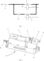
FIG. 1 is a schematic diagram of a principle of a power distribution device according to an embodiment of the present disclosure; -
FIG. 2 is a schematic three-dimensional assembly diagram of a power distribution device according to an embodiment of the present disclosure; -
FIG. 3 is a schematic three-dimensional exploded view of a power distribution device according to an embodiment of the present disclosure; -
FIG. 4 is a schematic plane view of a power distribution device according to an embodiment of the present disclosure; -
FIG. 5 is a schematic plane view of a power distribution device according to an embodiment of the present disclosure with an upper cover being removed; -
FIG. 6 is a schematic plane view of a power distribution device according to an embodiment of the present disclosure with an upper cover and a bottom shell being removed; and -
FIG. 7 is another schematic plane view of a power distribution device according to an embodiment of the present disclosure. - To make the objectives, technical solutions, and advantages of the present disclosure more apparent and clearer, the following describes the present disclosure in further detail with reference to the accompanying drawings and embodiments. It should be understood that, the specific embodiments described herein are merely used for explaining the present disclosure rather than being used for limiting the present disclosure.
- It should be noted that, terms "arrangement" and "connection" should be broadly understood, for example, which may be direct arrangement and connection, or indirect arrangement and connection through a central component or a central structure.
- In addition, in the embodiments of the present disclosure, orientation or position relationships indicated by the terms such as "longitudinal", "transverse", "length", "width", "thickness", "on", "below", "front", "back", "left", "right", "vertical", "horizontal", "top", "bottom", "inside", and "outside" are based on the orientation or positional relationship shown in the accompanying drawings or the conventional placing state or use state, which are only for the convenience of describing the present disclosure and simplifying the description, and does not indicate or imply that the referred structure, feature, device, or element should have a specific orientation or positional relationship, nor should it be constructed and operated in a specific orientation. Therefore, such terms should not be construed as a limitation on the present disclosure. In the description of the present disclosure, unless stated otherwise, the meaning of "multiple" is two or more than two.
- Various specific technical features and embodiments described in the foregoing specific implementations may be combined in any proper manner in the case of no contradiction. For example, different implementations may be formed through the combination of different specific technical features/embodiments. In order to avoid unnecessary repetition, various possible combinations of various specific technical features/embodiments are not described separately in the present disclosure.
- As shown in
FIG. 1 to FIG. 6 , an embodiment of the present disclosure provides a power distribution device. The power distribution device includes ahousing 9, a precharging circuit module, and a main positive circuit module. Thehousing 9 has a mounting cavity. The precharging circuit module is configured to precharge a capacitor element in an electrical appliance, and includes aprecharging relay 8. The precharging relay is connected with thehousing 9. The main positive circuit module is configured to be closed after the precharging circuit module is opened, and the main positive circuit module and the precharging circuit module are stacked in the mounting cavity in an up-down direction. The main positive circuit module includes afuse 2 and amain relay core 4, and themain relay core 4 is connected with thehousing 9. The power distribution device has an input terminal and a first output terminal. Afirst end 22 of thefuse 2 is the input terminal or connected with the input terminal, asecond end 21 of thefuse 2 is connected with afirst end 41 of themain relay core 4, and asecond end 40 of themain relay core 4 is the first output terminal or connected with the first output terminal. A first end of the precharging circuit module is connected with the input terminal or thesecond end 21 of thefuse 2, and a second end of the precharging circuit module is connected with thesecond end 40 of themain relay core 4 or the first output terminal. In this embodiment, themain relay core 4 is a semi-finished relay without shell at least, that is, the main relay is no longer mounted and used according to the finished product, but used with the semi-finished product (core). Structures of various components in the power distribution device are cooperatively and interactively designed, and the main positive circuit module and the precharging circuit module are arranged on thehousing 9 in a local or overall stacking mode. In this way, the utilization rate of the internal space of the power distribution device is high, and the components do not affect each other, so that the damaged components can be replaced independently, which is beneficial to improving the product qualification rate and reducing the after-sales loss of the products, and the application cost is low. The power distribution device provided in this embodiment of the present disclosure is a controller or a component for connection and disconnection between an electric energy storage element (such as a battery module) and an electrical appliance, and is mainly applicable to control places where a loop generates a great current during power-on and power-off, such as an electric car, an electric ship, an electric rail transit, or an airplane. During normal use of the power distribution device, theprecharging relay 8 is first closed to charge the capacitor element in the electrical appliance product, and the resistor in the precharging circuit module limits the current within a reasonable range. After the precharging is completed, themain relay core 4 is closed and theprecharging relay 8 is opened, thereby completing the power-on process and continuing the power supply. When the electrical appliance is short-circuited, thefuse 2 can be passively forced to fuse and disconnect the electrical appliance from the power supply to protect the internal components of the electrical appliance from damage. - In an embodiment, the precharging circuit module further includes a
precharging resistor 72. In this embodiment, theprecharging resistor 72 is a wire-wound resistor. Theprecharging relay 8 and themain relay core 4 are respectively seated to two ends of the mounting cavity, and thefuse 2 and theprecharging resistor 72 are arranged between theprecharging relay 8 and themain relay core 4. Thefuse 2 and theprecharging resistor 72 may be close to theprecharging relay 8 and themain relay core 4, and theprecharging resistor 72 is seated to a bottom of the mounting cavity. Thefuse 2 is located above theprecharging resistor 72 and has a reasonable and compact structure with a high space utilization rate. - In an embodiment, the
housing 9 includes abottom shell 6 and asurface cover 1. Thesurface cover 1 may be connected with thebottom shell 6 through a snap-fit structure or a locking member to form the mounting cavity, and theprecharging relay 8 may be connected with thebottom shell 6 through the clamping structure, so that the assembly efficiency is high. Themain relay core 4 may be connected with thebottom shell 6 through a potting structure (potting adhesive is solidified), so that the heat dissipation performance is improved and the product reliability is high. - In an embodiment, an upper part of the
surface cover 1 corresponding to theprecharging relay 8 is provided with a first mountinghole 101, and an upper part of thesurface cover 1 corresponding to themain relay core 4 is provided with asecond mounting hole 102 and athird mounting hole 103. Thefirst end 41 and the second end of themain relay core 4 are respectively located below thesecond mounting hole 102 and the third mountinghole 103. Thesurface cover 1 is provided with a mountingwindow 104 for thefuse 2 to be placed, and thefuse 2 may be seated to the mountingwindow 104 from top to bottom, so that thefuse 2 can be replaced without disassembling thesurface cover 1, which is convenient for maintenance. However, thefuse 2 needs to be replaced after being blown when the circuit is short-circuited, etc. The above design can effectively shorten the man-hours required for maintenance and can improve the maintenance efficiency. Theprecharging relay 8 is located below the first mountinghole 101. Thefirst end 22 of thefuse 2 extends to a position above the first mountinghole 101, and thesecond end 21 of thefuse 2 extends to a position above thesecond mounting hole 102. Thefirst end 41 of themain relay core 4 is located below thesecond mounting hole 102, thesecond end 40 of themain relay core 4 is located below the third mountinghole 103, and thesecond end 21 of thefuse 2 is connected with thefirst end 41 of themain relay core 4 through afirst locking member 3 passing through thesecond mounting hole 102. Thefirst locking member 3 may be a bolt, and structural members such as copper bars are not needed, so that the structure is simple and compact and the reliability is desirable. - In an embodiment, the power distribution device further has a second output terminal, and includes a connecting
wire harness 5. Afirst end 51 of the connectingwire harness 5 is inserted into theprecharging relay 8 through a first connecting terminal (an insert terminal), so that the assembly and maintenance are convenient. Asecond end 52 of the connectingwire harness 5 may be the second output terminal, and thesecond end 52 of the connectingwire harness 5 may be a connecting copper bar terminal. - In an embodiment, the
first end 71 of theprecharging resistor 72 is inserted into abody 81 of theprecharging relay 8 through the second connecting terminal (an insert terminal), so that the assembly and maintenance are convenient. Aresistor wire harness 7 is connected between thesecond end 73 of theprecharging resistor 72 and theprecharging resistor 72. Thehousing 9 is provided with a wire slot for accommodating theresistor wire harness 7. Thesecond end 73 of theprecharging resistor 72 is arranged above thesecond end 21 of thefuse 2, and the first locking member 3 (bolt) may pass through thesecond end 73 of theprecharging resistor 72 and thesecond end 21 of thefuse 2 and be connected with thefirst end 41 of themain relay core 4. - In an embodiment, the
first end 22 of thefuse 2 is the input terminal and is provided with a first hole for a fastening screw to pass through. The first output terminal is provided with a second hole for a fastening screw to pass through. The input terminal may be connected with a battery through the fastening screw, and the first output terminal may be connected with the electrical appliance through the fastening screw, so that the connection reliability is desirable. - In an embodiment, an upper end of the
surface cover 1 is provided with abaffle 110, and thesecond mounting hole 102 and the third mountinghole 103 are respectively located on two sides of thebaffle 110, thereby achieving better safety and reliability. The upper end of thesurface cover 1 is a part of thehousing 9 opposite to thebottom shell 6. - In an embodiment, the
bottom shell 6 is provided with an elastic sheet configured to abut against a side surface of theprecharging resistor 72, and thesurface cover 1 is provided with a positioning rib configured to abut against an end surface of theprecharging resistor 72. The limiting structure, the clamping structure, and the upper cover are mated with each other for limiting and fixation, and components such as screws are not needed, so that the assembly efficiency is high and the material management cost is low. - The present disclosure further provides a transportation device. The transportation device has the power distribution device, and the transportation device may be an electric vehicle, an electric ship, an electric rail transit, an airplane, or the like.
- For the assembly process of the power distribution device provided in an embodiment of the present disclosure, reference may be made to the following.
- The
main relay core 4 is placed at one end in thebottom shell 6, and themain relay core 4 is fixed to thebottom shell 6 by potting adhesive. - The
body 81 of theprecharging relay 8 is placed at the other end in thebottom shell 6, and theprecharging relay 8 is fixed to thebottom shell 6 through a snap-fit structure. - The
first end 51 of the connectingwire harness 5 is connected with thebody 81 of theprecharging relay 8 through an insert terminal. - A precharging resistor 72 (wire-wound resistor) is placed in the
bottom shell 6, and theprecharging resistor 72 is located between themain relay core 4 and thebody 81 of theprecharging relay 8. Thefirst end 71 of theprecharging resistor 72 is connected with thebody 81 of theprecharging relay 8 through the insert terminal, theresistor wire harness 7 is placed into the wire slot, and then the precharging resistor 72 (wire-wound resistor) is fixed to the elastic sheet of thebottom shell 6 through the positioning rib of the upper cover. - The upper cover and the
bottom shell 6 are mounted and fixed by a snap. - The
fuse 2 is placed in the mountingwindow 104 of the upper cover, thefirst end 22 of thefuse 2 is located in the first mountinghole 101, thesecond end 21 of thefuse 2 is located in thesecond mounting hole 102, and thesecond end 73 of theprecharging resistor 72 is placed on thesecond end 21 of thefuse 2 and is connected with thefirst end 41 of themain relay core 4 by using the first locking member 3 (screw). - During the operation of the power distribution device, for the current trend, reference may be made to the following description (in this embodiment, the input terminal is a
current input terminal 1001, and the first output terminal and the second output terminal are thecurrent output terminal 1002, as shown inFIG. 1 to FIG. 7 ). - I. Pre-power-on process: An external control system determines the start of pre-power-on. An input voltage of the
precharging relay 8 enters thebody 81 of theprecharging relay 8, and theprecharging relay 8 starts operating. First, an input current enters thefuse 2 from thefirst end 22 of thefuse 2, enters theprecharging resistor 72 through a joint of thesecond end 21 of thefuse 2 and thesecond end 73 of theprecharging resistor 72, then enters theprecharging relay 8 through a joint of thefirst end 71 of theprecharging resistor 72 and theprecharging relay 8, finally flows out to the connectingwire harness 5 through a joint of theprecharging relay 8 and thefirst end 51 of the connectingwire harness 5, and finally flows out from the connectingwire harness 5. - II. Pre-power-on and power-off process: After the external control system determines that the pre-power-on is completed, the input voltage of the
main relay core 4 enters themain relay core 4, themain relay core 4 starts operating, theprecharging relay 8 stops operating, and the current stops at theprecharging resistor 72. - III. Discharge process: The
main relay core 4 starts operating. After pre-power-on and power-off (power-off of the precharging circuit module), the current enters thefuse 2 from thefirst end 22 of thefuse 2, enters themain relay core 4 through a joint of thesecond end 21 of thefuse 2 and thefirst end 41 of themain relay core 4, and finally flows out from themain relay core 4. - The core component of the main relay is selected as the power distribution device and the transportation device having the power distribution device provided in the embodiments of the present disclosure, instead of the finished product of the conventional main relay. That is, the
main relay core 4 is selected, and the housing of the conventional relay product itself is removed. The mounting space required for the relay is reduced, the potting structure is adopted for mounting, and a mounting and fixation point for mounting the conventional relay is removed, thereby saving the mounting space and product cost. - In addition, fastening screw mounting pins of the
conventional precharging relay 8 product itself are further canceled, and the mounting space required is reduced. Instead, theprecharging relay 8 and thebottom shell 6 are mounted together by snaps, which saves the mounting space and product cost. Moreover, unlike the conventional manner of side-by-side arrangement, the main positive circuit module and the precharging circuit module are stacked with the former atop the latter, and are coordinatedly arranged in the housing, which makes full use of the redundant space within the module. Theprecharging resistor 72 is fixed by using the positioning rib of the upper cover and the elastic sheet of thebottom shell 6. The fastening screw mounting pins of theconventional precharging resistor 72 are removed, which further saves the mounting space and product cost. In addition, thefuse 2 and themain relay core 4 are locked with thesecond end 21 of thefuse 2 and thefirst end 41 of themain relay core 4 through fastening screws, so that the conventional connecting copper bar transfer mode is canceled, which is also beneficial to saving the mounting space and product cost, and the utilization rate of the internal space of the power distribution device is high. Moreover, no mutual influence exists between components, and the damaged components can be replaced separately, which is beneficial to increasing the product qualification rate and reducing the after-sales loss of products, and the application cost is low. - The foregoing descriptions are merely preferred embodiments of the present disclosure, but are not intended to limit the present disclosure. Any modification, equivalent replacement, or improvement made within the spirit and principle of the present disclosure shall fall within the protection scope of the present disclosure.
Claims (20)
- A power distribution device, comprising:a housing (9), having a mounting cavity;a precharging circuit module, configured to precharge a capacitor element in an electrical appliance and comprising a precharging relay (8), the precharging relay being connected with the housing; anda main positive circuit module, configured to be closed after the precharging circuit module is opened, the main positive circuit module and the precharging circuit module being stacked in the mounting cavity in an up-down direction, the main positive circuit module comprising a fuse (2) and a main relay core (4), and the main relay core being connected with the housing;the power distribution device having an input terminal and a first output terminal, a first end (22) of the fuse being the input terminal or connected with the input terminal, a second end (21) of the fuse being connected with a first end (41) of the main relay core, a second end (40) of the main relay core being the first output terminal or connected with the first output terminal, a first end of the precharging circuit module being connected with the input terminal or the second end of the fuse, and a second end of the precharging circuit module being connected with the second end of the main relay core or the first output terminal.
- The power distribution device according to claim 1, wherein the precharging circuit module further comprises a precharging resistor (72); the precharging relay and the main relay core are respectively seated to two ends of the mounting cavity; the fuse and the precharging resistor are arranged between the precharging relay and the main relay core; the precharging resistor is seated to a bottom of the mounting cavity; and the fuse is located above the precharging resistor.
- The power distribution device according to claim 2, wherein the fuse and the precharging resistor are close to the precharging relay and the main relay core.
- The power distribution device according to any of claims 1 to 3, wherein the precharging relay is connected with the housing through a clamping structure or a potting structure; and the main relay core is connected with the housing through a potting structure or a clamping structure.
- The power distribution device according to any of claims 1 to 4, wherein the housing comprises a bottom shell (6) and a surface cover (1); the surface cover is connected with the bottom shell through a snap-fit structure or a locking member to form the mounting cavity; the precharging relay is connected with the bottom shell through the clamping structure; and the main relay core is connected with the bottom shell through the potting structure.
- The power distribution device according to claim 5, wherein the surface cover is provided with a first mounting hole (101) corresponding to an upper part of the precharging relay; the surface cover is provided with a second mounting hole (102) and a third mounting hole (103) corresponding to an upper part of the main relay core; the surface cover is provided with a mounting window (104) for the fuse to be placed; the precharging relay is located below the first mounting hole; a first end of the fuse extends to a position above the first mounting hole; the second end of the fuse extends to a position above the second mounting hole; the first end of the main relay core is located below the second mounting hole; the second end of the main relay core is located below the third mounting hole; and the second end of the fuse is connected with the first end of the main relay core through a first locking member (3) passing through the second mounting hole.
- The power distribution device according to any of claims 4 to 6, wherein the potting structure is formed through solidification of potting adhesive.
- The power distribution device according to any of claims 1 to 7, further having a second output terminal, and comprising a connecting wire harness (5), a first end (51) of the connecting wire harness being inserted into the precharging relay through a first connecting terminal, and a second end (52) of the connecting wire harness being the second output terminal.
- The power distribution device according to claim 8, wherein the second end of the connecting wire harness is a connecting copper bar terminal.
- The power distribution device according to claim 8 or 9, wherein the first connecting terminal is an insert terminal.
- The power distribution device according to any of claims 8 to 10, wherein the input terminal is a current input terminal (1001); and the first output terminal and the second output terminal are current output terminals (1002).
- The power distribution device according to claim 2 or 3, wherein a first end (71) of the precharging resistor is inserted into the precharging relay through a second connecting terminal; a resistor wire harness (7) is connected with a second end (73) of the precharging resistor; the housing is provided with a wire slot for accommodating the resistor wire harness; and the second end of the precharging resistor is arranged above the second end of the fuse.
- The power distribution device according to claim 12, wherein the first end of the precharging resistor is inserted into a body (81) of the precharging relay through the second connecting terminal.
- The power distribution device according to claim 12 or 13, wherein the second connecting terminal is an insert terminal.
- The power distribution device according to any of claims 1 to 14, wherein the first end of the fuse is the input terminal and is provided with a first hole for a fastening screw to pass through; and the first output terminal is provided with a second hole for a fastening screw to pass through.
- The power distribution device according to claim 15, wherein the input terminal is connected with a battery through the fastening screw; and the first output terminal is connected with the electrical appliance through the fastening screw.
- The power distribution device according to claim 5 or 6, wherein an upper end of the surface cover is provided with a baffle (110); and the second mounting hole and the third mounting hole are respectively located on two sides of the baffle.
- The power distribution device according to claim 5 or 6, wherein the bottom shell is provided with an elastic sheet configured to abut against a side surface of the precharging resistor; the surface cover is provided with a positioning rib configured to abut against an end surface of the precharging resistor; and the precharging resistor is a wire-wound resistor.
- The power distribution device according to any of claims 1 to 18, wherein the main relay core is a relay without a housing.
- A transportation device, comprising:the power distribution device according to any of claims 1 to 19;an electric energy storage element; andan electrical appliance, the power distribution device being connected between the electric energy storage element and the electrical appliance, and being configured for connection and disconnection between an electric module and the electrical appliance.
Applications Claiming Priority (2)
| Application Number | Priority Date | Filing Date | Title |
|---|---|---|---|
| CN202121785979.XU CN215772569U (en) | 2021-08-02 | 2021-08-02 | Power distribution device and traffic transportation device with same |
| PCT/CN2022/101449 WO2023011048A1 (en) | 2021-08-02 | 2022-06-27 | Power distribution device and transportation device having power distribution device |
Publications (2)
| Publication Number | Publication Date |
|---|---|
| EP4333240A1 true EP4333240A1 (en) | 2024-03-06 |
| EP4333240A4 EP4333240A4 (en) | 2024-12-18 |
Family
ID=80109310
Family Applications (1)
| Application Number | Title | Priority Date | Filing Date |
|---|---|---|---|
| EP22851764.5A Pending EP4333240A4 (en) | 2021-08-02 | 2022-06-27 | POWER DISTRIBUTION DEVICE AND TRANSPORT DEVICE WITH THE POWER DISTRIBUTION DEVICE |
Country Status (9)
| Country | Link |
|---|---|
| US (1) | US12570150B2 (en) |
| EP (1) | EP4333240A4 (en) |
| JP (1) | JP7641412B2 (en) |
| KR (1) | KR102884290B1 (en) |
| CN (1) | CN215772569U (en) |
| AU (1) | AU2022322694B2 (en) |
| BR (1) | BR112023026521A2 (en) |
| CA (1) | CA3224304A1 (en) |
| WO (1) | WO2023011048A1 (en) |
Families Citing this family (2)
| Publication number | Priority date | Publication date | Assignee | Title |
|---|---|---|---|---|
| CN215772569U (en) | 2021-08-02 | 2022-02-08 | 比亚迪股份有限公司 | Power distribution device and traffic transportation device with same |
| CN119495853A (en) * | 2023-08-17 | 2025-02-21 | 宁德时代新能源科技股份有限公司 | Power distribution devices, batteries and electrical equipment |
Family Cites Families (12)
| Publication number | Priority date | Publication date | Assignee | Title |
|---|---|---|---|---|
| US6511331B2 (en) | 2000-11-28 | 2003-01-28 | Sumitomo Wiring Systems, Ltd. | Electrical junction box for a vehicle |
| JP6938589B2 (en) | 2015-11-04 | 2021-09-22 | 株式会社エンビジョンAescジャパン | Battery pack |
| CN205724734U (en) * | 2016-03-10 | 2016-11-23 | 矢崎(中国)投资有限公司 | Electrical junction box |
| KR102237376B1 (en) * | 2016-09-08 | 2021-04-06 | 삼성에스디아이 주식회사 | Battery pack |
| CN207339342U (en) | 2017-09-30 | 2018-05-08 | 厦门宏发电力电器有限公司 | Preliminary filling module with main positive relay |
| CN209150758U (en) * | 2018-12-05 | 2019-07-23 | 浙江宏舟新能源科技有限公司 | A kind of split type high capacity control box for electric powered motor internal storage battery |
| CN210792802U (en) * | 2019-08-30 | 2020-06-19 | 比亚迪股份有限公司 | Pre-charged power distribution unit |
| CN211195876U (en) * | 2019-11-29 | 2020-08-07 | 比亚迪股份有限公司 | Power distribution device and vehicle having the same |
| CN211208906U (en) * | 2019-12-30 | 2020-08-07 | 比亚迪股份有限公司 | Power distribution integrated modules and vehicles |
| CN211859635U (en) * | 2020-03-17 | 2020-11-03 | 上海瑞垒电子科技有限公司 | Pre-charging device with main positive relay |
| CN212380731U (en) * | 2020-06-28 | 2021-01-19 | 比亚迪股份有限公司 | Pre-charged power distribution devices and vehicles |
| CN215772569U (en) * | 2021-08-02 | 2022-02-08 | 比亚迪股份有限公司 | Power distribution device and traffic transportation device with same |
-
2021
- 2021-08-02 CN CN202121785979.XU patent/CN215772569U/en active Active
-
2022
- 2022-06-27 CA CA3224304A patent/CA3224304A1/en active Pending
- 2022-06-27 JP JP2023579018A patent/JP7641412B2/en active Active
- 2022-06-27 BR BR112023026521A patent/BR112023026521A2/en unknown
- 2022-06-27 AU AU2022322694A patent/AU2022322694B2/en active Active
- 2022-06-27 EP EP22851764.5A patent/EP4333240A4/en active Pending
- 2022-06-27 KR KR1020237041093A patent/KR102884290B1/en active Active
- 2022-06-27 WO PCT/CN2022/101449 patent/WO2023011048A1/en not_active Ceased
-
2023
- 2023-11-28 US US18/522,015 patent/US12570150B2/en active Active
Also Published As
| Publication number | Publication date |
|---|---|
| CN215772569U (en) | 2022-02-08 |
| US20240092174A1 (en) | 2024-03-21 |
| AU2022322694B2 (en) | 2025-08-14 |
| JP7641412B2 (en) | 2025-03-06 |
| BR112023026521A2 (en) | 2024-03-05 |
| WO2023011048A1 (en) | 2023-02-09 |
| CA3224304A1 (en) | 2023-02-09 |
| KR102884290B1 (en) | 2025-11-11 |
| EP4333240A4 (en) | 2024-12-18 |
| AU2022322694A1 (en) | 2024-01-18 |
| US12570150B2 (en) | 2026-03-10 |
| JP2024523484A (en) | 2024-06-28 |
| KR20240000609A (en) | 2024-01-02 |
Similar Documents
| Publication | Publication Date | Title |
|---|---|---|
| US12570150B2 (en) | Power distribution device and transportation device having power distribution device | |
| KR100920207B1 (en) | Power switching module for manufacturing battery module assembly | |
| CN215771395U (en) | Power battery BDU structure and vehicle | |
| WO2020056858A1 (en) | Energy system for new energy vehicle | |
| US9943001B2 (en) | Switch box | |
| US12014888B2 (en) | Circuit assembly | |
| CN108099681B (en) | Vehicle-mounted charging device | |
| JP2013114951A (en) | Power supply device and vehicle including the same, power storage device, coupling unit | |
| JP5530884B2 (en) | Power storage device | |
| WO2021078006A1 (en) | Wiring harness isolation plate assembly, battery module, battery pack and device | |
| US20240092286A1 (en) | Low-voltage power supply system and vehicle having same | |
| CN218456113U (en) | Battery pack and power system | |
| CN108263215A (en) | Battery cutout unit, battery system and electric vehicle | |
| CN118231727A (en) | Battery pack and electric equipment | |
| CN211428115U (en) | Accumulator fuse box for electric vehicle | |
| US20250349914A1 (en) | Multifunctional mounting bracket, battery mounting module, and battery pack | |
| CN119495853A (en) | Power distribution devices, batteries and electrical equipment | |
| CN218243323U (en) | Two-way input two-phase power module and power electronic equipment | |
| CN214588969U (en) | Electric motor car master-slave control integrated BMS protection board with communication | |
| CN217334289U (en) | Battery device | |
| CN222346777U (en) | Battery devices, electrical equipment and vehicles | |
| CN221862185U (en) | Self-powered high voltage distribution box | |
| WO2025185116A1 (en) | Housing structure of power distribution unit, power distribution unit, battery, and electrical device | |
| CN220527401U (en) | High-voltage fusing protection wiring structure of UPS cabinet | |
| CN223539804U (en) | Battery pack and electricity utilization device |
Legal Events
| Date | Code | Title | Description |
|---|---|---|---|
| STAA | Information on the status of an ep patent application or granted ep patent |
Free format text: STATUS: THE INTERNATIONAL PUBLICATION HAS BEEN MADE |
|
| PUAI | Public reference made under article 153(3) epc to a published international application that has entered the european phase |
Free format text: ORIGINAL CODE: 0009012 |
|
| STAA | Information on the status of an ep patent application or granted ep patent |
Free format text: STATUS: REQUEST FOR EXAMINATION WAS MADE |
|
| 17P | Request for examination filed |
Effective date: 20231127 |
|
| AK | Designated contracting states |
Kind code of ref document: A1 Designated state(s): AL AT BE BG CH CY CZ DE DK EE ES FI FR GB GR HR HU IE IS IT LI LT LU LV MC MK MT NL NO PL PT RO RS SE SI SK SM TR |
|
| DAV | Request for validation of the european patent (deleted) | ||
| DAX | Request for extension of the european patent (deleted) | ||
| A4 | Supplementary search report drawn up and despatched |
Effective date: 20241119 |
|
| RIC1 | Information provided on ipc code assigned before grant |
Ipc: B60K 1/04 20190101ALI20241113BHEP Ipc: H02J 7/00 20060101ALI20241113BHEP Ipc: H01H 85/02 20060101ALI20241113BHEP Ipc: H02B 1/18 20060101ALI20241113BHEP Ipc: H02B 1/48 20060101ALI20241113BHEP Ipc: H02B 1/46 20060101ALI20241113BHEP Ipc: H02B 1/26 20060101ALI20241113BHEP Ipc: H02J 4/00 20060101AFI20241113BHEP |